EP2605211A1 - Image processing apparatus, image processing method, and program - Google Patents
Image processing apparatus, image processing method, and program Download PDFInfo
- Publication number
- EP2605211A1 EP2605211A1 EP20120197177 EP12197177A EP2605211A1 EP 2605211 A1 EP2605211 A1 EP 2605211A1 EP 20120197177 EP20120197177 EP 20120197177 EP 12197177 A EP12197177 A EP 12197177A EP 2605211 A1 EP2605211 A1 EP 2605211A1
- Authority
- EP
- European Patent Office
- Prior art keywords
- pixel
- value
- image
- reconstructing
- difference
- Prior art date
- Legal status (The legal status is an assumption and is not a legal conclusion. Google has not performed a legal analysis and makes no representation as to the accuracy of the status listed.)
- Granted
Links
Images





Classifications
-
- A—HUMAN NECESSITIES
- A61—MEDICAL OR VETERINARY SCIENCE; HYGIENE
- A61B—DIAGNOSIS; SURGERY; IDENTIFICATION
- A61B6/00—Apparatus or devices for radiation diagnosis; Apparatus or devices for radiation diagnosis combined with radiation therapy equipment
- A61B6/52—Devices using data or image processing specially adapted for radiation diagnosis
-
- G—PHYSICS
- G06—COMPUTING OR CALCULATING; COUNTING
- G06T—IMAGE DATA PROCESSING OR GENERATION, IN GENERAL
- G06T12/00—Tomographic reconstruction from projections
-
- A—HUMAN NECESSITIES
- A61—MEDICAL OR VETERINARY SCIENCE; HYGIENE
- A61B—DIAGNOSIS; SURGERY; IDENTIFICATION
- A61B6/00—Apparatus or devices for radiation diagnosis; Apparatus or devices for radiation diagnosis combined with radiation therapy equipment
- A61B6/02—Arrangements for diagnosis sequentially in different planes; Stereoscopic radiation diagnosis
- A61B6/03—Computed tomography [CT]
-
- A—HUMAN NECESSITIES
- A61—MEDICAL OR VETERINARY SCIENCE; HYGIENE
- A61B—DIAGNOSIS; SURGERY; IDENTIFICATION
- A61B6/00—Apparatus or devices for radiation diagnosis; Apparatus or devices for radiation diagnosis combined with radiation therapy equipment
- A61B6/52—Devices using data or image processing specially adapted for radiation diagnosis
- A61B6/5258—Devices using data or image processing specially adapted for radiation diagnosis involving detection or reduction of artifacts or noise
-
- G—PHYSICS
- G06—COMPUTING OR CALCULATING; COUNTING
- G06T—IMAGE DATA PROCESSING OR GENERATION, IN GENERAL
- G06T12/00—Tomographic reconstruction from projections
- G06T12/10—Image preprocessing, e.g. calibration, positioning of sources or scatter correction
-
- G—PHYSICS
- G06—COMPUTING OR CALCULATING; COUNTING
- G06T—IMAGE DATA PROCESSING OR GENERATION, IN GENERAL
- G06T5/00—Image enhancement or restoration
- G06T5/20—Image enhancement or restoration using local operators
-
- G—PHYSICS
- G06—COMPUTING OR CALCULATING; COUNTING
- G06T—IMAGE DATA PROCESSING OR GENERATION, IN GENERAL
- G06T2207/00—Indexing scheme for image analysis or image enhancement
- G06T2207/10—Image acquisition modality
- G06T2207/10072—Tomographic images
- G06T2207/10112—Digital tomosynthesis [DTS]
-
- G—PHYSICS
- G06—COMPUTING OR CALCULATING; COUNTING
- G06T—IMAGE DATA PROCESSING OR GENERATION, IN GENERAL
- G06T2207/00—Indexing scheme for image analysis or image enhancement
- G06T2207/10—Image acquisition modality
- G06T2207/10116—X-ray image
-
- G—PHYSICS
- G06—COMPUTING OR CALCULATING; COUNTING
- G06T—IMAGE DATA PROCESSING OR GENERATION, IN GENERAL
- G06T2207/00—Indexing scheme for image analysis or image enhancement
- G06T2207/20—Special algorithmic details
- G06T2207/20004—Adaptive image processing
- G06T2207/20012—Locally adaptive
-
- G—PHYSICS
- G06—COMPUTING OR CALCULATING; COUNTING
- G06T—IMAGE DATA PROCESSING OR GENERATION, IN GENERAL
- G06T2207/00—Indexing scheme for image analysis or image enhancement
- G06T2207/20—Special algorithmic details
- G06T2207/20024—Filtering details
- G06T2207/20028—Bilateral filtering
-
- G—PHYSICS
- G06—COMPUTING OR CALCULATING; COUNTING
- G06T—IMAGE DATA PROCESSING OR GENERATION, IN GENERAL
- G06T2211/00—Image generation
- G06T2211/40—Computed tomography
- G06T2211/421—Filtered back projection [FBP]
-
- G—PHYSICS
- G06—COMPUTING OR CALCULATING; COUNTING
- G06T—IMAGE DATA PROCESSING OR GENERATION, IN GENERAL
- G06T2211/00—Image generation
- G06T2211/40—Computed tomography
- G06T2211/448—Computed tomography involving metal artefacts, streaking artefacts, beam hardening or photon starvation
Definitions
- the present invention relates to an image processing apparatus, an image processing method, and a program for use in tomographic image interpretation using X-rays.
- filtered back projection has been used as a method of mathematically obtaining a tomographic image at high speed and with high precision, and this method is a central reconstructing method even now.
- the projection images are filtered using a reconstruction filter such as ramp filter, Shepp & Logan filter, or the like for amplifying a high frequency and, thereafter, back projection is performed.
- a reconstruction filter such as ramp filter, Shepp & Logan filter, or the like for amplifying a high frequency
- back projection is performed.
- Japanese Patent Application Laid-Open No. H08-019533 discloses a method whereby a high absorber is computationally removed from a projection image, the removed portion is interpolated, and thereafter, a tomogram is reconstructed.
- Japanese Patent Application Laid-Open No. 2008-528228 discloses a method whereby a direction-dependent adaptive filtering process is performed to a streak artefact in a tomographic image, thereby reducing the streak artefact.
- Japanese Patent Application Laid-Open No. 2006-000226 discloses a method whereby a reconstruction filter in which a high frequency is suppressed is used in a high absorber and an ordinary reconstruction filter is used in a low absorber, thereby reducing a streak artefact.
- the invention is made in consideration of the foregoing problems and it is desirable to provide a method whereby when a tomographic image is reconstructed by a filtered back projection, a streak artefact by a high absorber is reduced effectively without causing an image blur.
- an image processing apparatus for executing a reconstruction process of a tomographic image according to claims 1 to 11.
- a third aspect of the invention provides a method according to claim 18.
- a fourth aspect of the invention provides a method according to claims 19 and 20.
- a computer program and storage means for performing the methods are defined in claims 21 and 22.
- the streak artefact by the high absorber such as a metal or the like can be reduced effectively without causing the image blur.
- FIG. 1 is a diagram illustrating a functional construction of an image processing apparatus in a first embodiment.
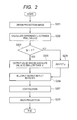
- FIG. 2 is a flowchart illustrating a flow for an image process in the first embodiment.
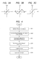
- FIGS. 3A, 3B and 3C are diagrams each illustrating an example of an output of a function in the first embodiment.
- FIG. 4 is a flowchart illustrating a flow for an image process in a second embodiment.
- FIG. 5 is a flowchart illustrating a flow for an image process in a third embodiment.
- FIGS. 6A, 6B and 6C are diagrams each illustrating an example of an output of a function in the third embodiment.
- FIG. 7 is a flowchart illustrating a flow for an image process in a fourth embodiment.
- FIG. 8 is a diagram illustrating a functional construction of an image processing apparatus in a fifth embodiment.
- FIG. 9 is a flowchart illustrating a flow for an image process in the fifth embodiment.
- FIG. 10 is a diagram illustrating an example of a setting of a concerned area in the fifth embodiment.
- FIG. 11 is a diagram illustrating an example of an image histogram analysis in the fifth embodiment.
- FIG. 12 is a diagram illustrating relations among variables of 3-dimensional coordinate axes in the first embodiment.
- FIG. 13 is a diagram illustrating a change in pixel value of a projection image in the first embodiment.
- FIG. 14 is a diagram illustrating an example of the projection image in the first embodiment.
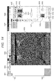
- FIG. 15A is a diagram illustrating an example of a setting display screen of tomosynthesis in the first embodiment.
- FIG. 15B is a diagram illustrating another example of the setting display screen of tomosynthesis in the first embodiment.
- CT computed tomography
- PET positron emission tomography
- MRI magnetic resonance imaging
- FIG. 1 illustrates a functional construction of an image processing apparatus 100 according to an embodiment 1.
- An X-ray tube 101 irradiates X-rays from a plurality of irradiation angles.
- a subject to be tested (hereinbelow, referred to as a subject) 102 is positioned on a bed 103.
- An X-ray detector 106 receives the X-rays and obtains X-ray images.
- a mechanism control unit 105 controls positions of the X-ray tube 101 and the X-ray detector 106.
- a photographing control unit 104 electrically controls the X-ray detector 106 and obtains X-ray images.
- An X-ray generating apparatus control unit 107 electrically controls the X-ray tube so as to generate the X-rays under predetermined conditions.
- An X-ray photography system control unit 108 controls the mechanism control unit 105 and the photographing control unit 104 and in conjunction with the detector 106 obtains X-ray images from a plurality of X-ray irradiation angles.
- An image processing unit 109 and an image storing unit 112 are provided for the X-ray photographing system control unit 108 and one or a plurality of computers are built therein.
- a main control unit such as a CPU (central processing unit) or the like and storing units such as ROM (Read Only Memory), RAM (Random Access Memory), and the like are provided for the computer.
- a graphic control unit such as a GPU (Graphics Processing Unit) or the like, a communicating unit such as a network card or the like, an input/output unit such as keyboard, display, touch panel, or the like, and so on may be also provided for the computer.
- Those component units are connected by a bus or the like and are controlled by a method whereby the main control unit executes programs stored in the storing unit. Further, a monitor 110 for displaying photographed projection images and an operating unit 111 which is operated by the user are provided for the output and input of the X-ray photographing system control unit 108.
- the image processing unit 109 reconstructs the obtained X-ray images and forms a tomographic image.
- the image processing unit 109 has a pixel value differencing unit 113, a function value calculating unit 114, a multiplying unit 115, a convolution unit 116, and a back projection unit 117.
- a plurality of X-ray images (hereinbelow, also referred to as projection images or radiation projection images) from the various X-ray irradiation angles obtained from the X-ray detector 106 by the X-ray photographing system control unit 108 through the photographing control unit 104 are input to the image processing unit 109.
- a defect correction, a gain correction, a logarithmic transformation, and the like are preliminarily performed to the projection images.
- the pixel value differencing unit 113 calculates a difference value between the value of a filtering target pixel and the value of a pixel which exists around the filtering target pixel (i.e. a peripheral pixel or a neighbouring pixel) and which is used for a filtering process.
- the function value calculating unit 114 On the basis of the difference value calculated in the pixel value differencing unit 113, when an absolute value of the difference value is equal to or smaller than a predetermined value, the function value calculating unit 114 outputs the difference value as it is, and when the absolute value is larger than the predetermined value, the function value calculating unit 114 outputs a value having an absolute value that is smaller than the absolute value of the difference value and having a sign that is the same as that of the difference value. This output value may be, for example, equal to 0.
- the multiplying unit 115 multiplies an output of the function value calculating unit 114 by a reconstruction filter coefficient.
- a reconstruction filter an ordinary filter which is used in a filtered back projection such as ramp filter, Shepp & Logan filter, or the like is used.
- the convolution unit 116 executes a filtering process to the projection images by using the reconstruction filter coefficient used in the multiplying unit 115.
- the back projection unit 117 executes a back projection by using the filtered projection images and forms a tomographic image.
- the back projection includes a step of performing an integrating process to the reconstruction-filtered projection images.
- the reconstruction-filtered projection images are integrated with respect to an irradiation angle ⁇ .
- the irradiation angle is, for example, an angle between 1) the direction connecting a centre of a radiation detector and a focal point of the X-ray tube, and 2) the direction perpendicular to the detecting surface of the radiation detector. Since the radiation projection images which are actually obtained are discrete, an approximate integrating process is executed in consideration of such a focal point.
- the tomographic image can be formed in which a streak artefact due to the high absorber is eliminated and the image blur hardly occurs. A frequency response of the filter does not change throughout this integrating process.
- FIG. 2 An example of an image processing flow in the image processing apparatus 100 illustrated in FIG. 1 will be described with reference to FIG. 2 .
- projection images are obtained in S201. They are obtained by photographing the subject 102 using X-rays while changing the X-ray irradiation angle of the X-ray tube 101 within a range from -40° to 40°. Any number of photograph images can be obtained. For example, if 80 projection images are photographed at 15 FPS (frames per second) while changing the angle one degree (1°) at a time, the images can be collected in about 6 seconds. Any photographing condition of the X-ray can furthermore be set, but it is sufficient to photograph the images at about 100 kV and 1 mAs in the case of photographing a human chest or the like. A distance between the X-ray detector 106 and the X-ray tube 101 is set to a setting range of about 100 to 150 cm.
- the X-ray detector 106 is moved parallel, but in the direction opposite, to the X-ray tube 101.
- a parallel movement amount at this time is obtained by Ptan ⁇ assuming that a projection angle is set to ⁇ and a distance between a rotational centre of the X-ray tube 101 and a centre of the X-ray detector 106 is set to D. If the X-ray detector 106 is moved parallel to the X-ray tube as mentioned above, even if the X-ray irradiating direction of the X-ray tube 101 is changed, a reference axis always passes through the centre of the X-ray detector 106.
- Pre-processes may include a correction of defective pixels and a dark current of the X-ray detector 106, a correction of an irradiation fluctuation that is caused by the X-ray tube 101, a logarithmic transformation, and the like. It is sufficient to use the processes as these pre-processes which are generally executed in the X-ray detector.
- the pixel values of the projection images are set to values obtained by linearly integrating an X-ray attenuation coefficient. The X-ray images are reconstructed on the basis of the additivity of the X-ray attenuation coefficient.
- a difference value p between a filtering target pixel and a peripheral pixel which is used in the filtering process is calculated by using the pixel value differencing unit 113.
- the difference may be, for instance, in intensity, luminance or shade in a greyscale.
- of the difference value calculated in S202 is compared with a predetermined threshold value ⁇ .
- ⁇ a predetermined threshold value
- ), or the like is output in S205.
- the processes of S203 to S205 are executed by the function value calculating unit 114 and their results are expressed by a piecewise linear function F(p) as shown in FIGS. 3A to 3C . In the piecewise linear function F(p) shown in FIGS.
- the difference value (if p has a value up to ⁇ ) or the value smaller than the difference value is output on the basis of a magnitude relation between the threshold value and the difference value between the pixel value of the processing target pixel by the reconstruction filter and the pixel value of the peripheral pixel (of the target pixel of the filtering process) which is used in the reconstruction filtering process.
- the effect in the image is a reduced contrast between neighbouring pixels in the case where the input contrast is very high (over the threshold). Such characteristics contribute to the proper reduction of the metal artefact, which appears as a high contrast artefact.
- a reconstruction filter function such as ramp filter, Shepp & Logan filter, or the like is multiplied by an output result, that is, F(p) in S204 and S205, using the multiplying unit 115. That is, the reconstruction filter function is converted into what is called an epsilon ( ⁇ ) filter function using an epsilon ( ⁇ ) filter.
- the difference value hereinbelow referred to as a difference signal
- the difference signal it is considered that a correlation between the processing target pixel and the peripheral pixel is strong, and it is intended to actively use that peripheral pixel.
- an influence of the pixel value which differs significantly (i.e. which has a high contrast) from an object portion such as a metal or the like can be reduced.
- the ⁇ filter since the difference between the pixel values is used as a threshold value ⁇ , that is, a parameter, the parameter can be more properly and easily adjusted with respect to the projection images which are obtained by the radiography.
- a data-dependent type of process serving as a process for changing the coefficient of the filter in accordance with a nature of the image can be also used in place of the ⁇ filter.
- a reconstruction filter h(t) multiplied by F(p) in S206 is convoluted along with the projection images. This process is executed in the convolution unit 116 and is expressed by the following equation (1) in the case of the tomosynthesis.
- G x t ⁇ ⁇ z t ⁇ ⁇ ⁇ - ⁇ ⁇ ⁇ F ⁇ q x t ⁇ z t ⁇ ⁇ - q x t ⁇ ⁇ z t ⁇ ⁇ ⁇ h x t ⁇ ⁇ x t ⁇ J C x t ⁇ z t ⁇ d x t
- x t and z t denote coordinates on the X-ray detector 106.
- x t indicates the coordinate which is parallel with the moving direction of the X-ray detector 106.
- x t ' is the position of another pixel.
- z t indicates the coordinate which is perpendicular to the moving direction of the X-ray detector 106.
- ⁇ denotes the projection angle.
- q(x t , z t , ⁇ ) denotes pixel values on the X-ray detector 106.
- J c denotes a coefficient for converting an integration variable into a geometrical construction of the tomosynthesis. J c is expressed by the following equation (1-1).
- 3-dimensional coordinate axes x, y, and z denote a reconstruction coordinate space and an isocenter is used as an origin.
- An xz plane is a plane which is parallel with a detecting surface of the X-ray detector 106 and is a plane which passes through an isocenter 301.
- the y axis is a normal which is perpendicular to the detecting surface of the X-ray detector 106.
- x t and z t denote the x coordinate and the z coordinate of a point at which a straight line 303 connecting a point on the X-ray detector 106 and a focal point 302 of the X-ray tube 101 crosses the xz plane.
- the angle ⁇ between the y axis and a reference axis of the X-ray tube 101 is an X-ray irradiation angle (projection angle).
- the equation (1-1) expresses a cosine value of an angle between the straight lines 303 and 304.
- the straight line 304 is a line connecting the focal point 302 and a point at which a perpendicular put down to the z axis from a point where the straight line 303 crosses the xz plane.
- the value for line 303 is x t + sin ⁇ t 2 + D t cos ⁇ t 2 and the value for line 304 is D t so that the cosine of the angle between lines 303 and 304 can be determined using the cosine rule, giving J c .
- a 2-dimensional filtered projection image G(x t ', z t , ⁇ ) is obtained where x t ' is a pixel position (or, more specifically, a distance from the z-axis) of a neighbouring or peripheral pixel.
- the nonlinear function shown in FIG. 3A is used as an example.
- the invention is not limited to it but even if a function shown in FIG. 3B or FIG. 3C is used, such a reconstruction can be performed that the influence of the pixel of the metal portion is reduced.
- ⁇ m denotes a maximum projection angle.
- J B denotes a coefficient for converting an integration variable into a geometrical construction of the tomosynthesis and is expressed by the following equation (2-1).
- J B x t ⁇ ⁇ z t ⁇ ⁇ ⁇ r ⁇ D ⁇ cos ⁇ D 2 ⁇ cos 2 ⁇ ⁇ + z t 2 ⁇ D t + x t ⁇ ⁇ sin ⁇ t cos ⁇ t ⁇ D t - D t D ⁇ r ⁇ y ⁇ 2
- r denotes a 3-dimensional vector showing a reconstruction point in which the isocentre is set to an origin.
- ⁇ denotes a unit vector along the reference axis (centre of the beam) of the X-ray tube.
- the invention can be also applied to the ordinary X-ray CT.
- the invention can be also applied to the reconstruction using the filtered back projection such as SPECT, PET, MRI, or the like.
- SPECT positron emission tomography
- MRI magnetic resonance imaging
- a reconstructing method in the case of applying the invention to them it is sufficient to use a Feldkamp method or a fan beam reconstructing method which is generally used.
- a functional construction is substantially the same as that of the embodiment 1 and is as illustrated in FIG. 1
- a processing flow is also substantially the same as that of the embodiment 1, and a description of overlapped portions is omitted here.
- a process of S301 is executed by using the function value calculating unit 114 in place of the processes of S203 to S205 in the embodiment 1. That is, in S301, a weight coefficient is calculated in accordance with the absolute value
- of the difference value. For example, it is expressed by the following equation (3). w ⁇ q x t ⁇ ⁇ z t ⁇ ⁇ - q x t ⁇ z t ⁇ ⁇ exp - q x t ⁇ ⁇ z t ⁇ ⁇ - q x t ⁇ z t ⁇ ⁇ 2 2 ⁇ ⁇ 2
- ⁇ denotes a value which is experimentally decided in accordance with a photographing region or the like and is set in a manner similar to ⁇ in the embodiment 1.
- the reconstruction filter function such as ramp filter, Shepp & Logan filter, or the like is multiplied by a weight output result w(t) of S301 by the multiplying unit 115.
- the 2-dimensional filtered projection image G(x t ', z t , ⁇ ) is obtained.
- the process of S208 is the same as that in the embodiment 1.
- a flow for an image process in an embodiment 3 will be described with reference to FIG. 5 .
- a functional construction is substantially the same as that of the embodiment 1 and is as illustrated in FIG. 1
- a processing flow is also substantially the same as that of the embodiment 1, and a description of overlapping portions is omitted here.
- the streak artefact caused by the high absorber can be reduced effectively by the method and apparatus in embodiment 1, there is a case where a contrast of the high absorber is also deteriorated.
- the contrast of the high absorber is also maintained and the streak artefact (surrounding the high absorber) is reduced.
- a process of S403 is executed by using the function value calculating unit 114 in place of the process of S203 in the embodiment 1. That is, in S403, the difference value p calculated in S202 is compared with the predetermined threshold value ⁇ . Thus, if the difference value p is equal to or smaller than the threshold value ⁇ , the difference value p is output as it is in S404. If the difference value p is larger than the threshold value ⁇ , a value with an absolute value smaller than or equal to the threshold value ⁇ , for example, 0, ⁇ , ⁇ (2 ⁇ -
- the difference value is output. If the absolute value of the difference value is larger than the threshold value, a value smaller than the difference value is output. Thus, while the metal portion is extracted to the tomosynthesis image, the metal artefact can be reduced.
- the influence of the high absorber can be eliminated in the filtering of the low absorber portion.
- the streak artefact can be suppressed.
- the frequency response of the filter does not change, the image blur is also reduced.
- the low absorber portion is also considered in the filtering of the high absorber portion. Consequently, the contrast in the high absorber portion can be maintained.
- a functional construction is substantially the same as that of the embodiment 2 and is as illustrated in FIG. 1
- a processing flow is also substantially the same as that of the embodiment 2, and a description of overlapping portions is omitted here.
- the streak artefact by the high absorber can be effectively reduced by embodiment 2, there is a case where the contrast of the high absorber is also deteriorated.
- the contrast of the high absorber is also maintained and the streak artefact is reduced.
- the influence of the high absorber can be reduced in the filtering of the low absorber portion.
- the streak artefact can be suppressed.
- the frequency response of the filter is not easily changed, the image blur is also reduced.
- the low absorber portion is also considered in the filtering of the high absorber portion. Consequently, the contrast in the high absorber portion can be maintained.
- FIGS. 8 to 11 A flow for an image process in an embodiment 5 will be described with reference to FIGS. 8 to 11 .
- An image processing apparatus 600 illustrated in FIG. 8 differs from the image processing apparatus 100 of the embodiment 1 with respect to a point that in an image processing unit 602, a parameter setting unit 601 is added to the image processing unit 109 of the embodiment 1.
- An image process shown in FIG. 9 differs from the image process in the embodiment 1 with respect to a point that a process of S701 is added to the process shown in FIG. 2 .
- a specific setting method of the threshold value ⁇ will be described in such a form. It can be easily presumed that the setting method of the embodiment can be also applied to the embodiments 2 to 4.
- the photographed projection image is displayed to the monitor 110.
- the user designates two points, one being of a metal portion 801 and another being of a bone portion 802 on the projection image as illustrated in FIG. 10 .
- S701 a difference between pixel values of those two designated portions is calculated and set to the threshold value ⁇ by the parameter setting unit 601.
- ⁇ ⁇ 2 ⁇ 2 ⁇ ln ⁇ 2
- the apparatus in such a manner that the projection image is analysed, the metal and a portion other than the metal are automatically extracted, and the threshold value is set by using a difference between their values. For example, as illustrated in FIG. 11 , if a histogram of the projection image is formed, since the metal portion strongly absorbs the X-ray, it has a peak in a low pixel value (i.e. a large number of low-valued pixels in the image will be represented as a peak in such a histogram). It is sufficient to detect such a peak and set a difference 901 between the peak and a distribution base of an object to be photographed to the threshold value ⁇ .
- FIG. 14 is an example of a photographic display screen which is displayed on the monitor 110 by the display control unit of the X-ray photographic system control unit 108 according to the embodiment.
- the photographic display screen is a display screen which is used in such a manner that a cursor displayed likewise on the monitor 110 is operated by a mouse device or the like included in the operating unit 111, thereby photographing projection images and confirming the photographed images.
- Data of the photographed images on the display screen is stored in, for example, a memory in the X-ray photographic system control unit and is displayed in such a layout as shown in FIG. 14 in accordance with control of the display control unit.
- An inspection information display tab 1401 is a display tab for displaying information regarding an inspection which is being progressed at present.
- the tab 1401 is displayed by the display control unit in accordance with information of the patient as a photographing target and the setting of a photographing mode.
- a past image display tab 1402 is a display tab for displaying information of the images which were photographed in the past. By clicking the display screen using the cursor position and the operating unit 111, the tab 1402 is displayed on the front face of the monitor 110 in place of the inspection information display tab.
- a display style change button 1403 is a button or a group of buttons for changing a display style of the radiography image which is displayed in a selection image display area 1404.
- one of the following display styles is selected: a first display style in which only one selected image is displayed; a second display style in which a plurality of radiography images regarding the same inspection or same patient are arranged and displayed; and a third display style in which a plurality of projection images or frame images obtained by the tomosynthesis photography, radioscopy or cinemascope photography, or the like are arranged and displayed.
- the photographed images are displayed in the display style selected by the display control unit.
- a selected tomographic image is displayed in the image display area 1404.
- Patient information of the present inspection is displayed in a display area 1405.
- the patient information is, for example, information peculiar to the patient such as ID, name, sex, age, and the like of the patient.
- Execution information as information which was sent from the X-ray generating apparatus control unit 107 and is related with the radiation irradiation performed in association with the image which is being displayed is displayed in a display area 1406.
- the execution information is, for example, information regarding photographing time, total irradiation time, total area dose, total absorption dose, and total air kerma of a group of projection images which are used in the reconstruction of the tomographic image displayed in the image display area 1404.
- an amount of available memory of the HDD hard disc drive
- the photographic information set on the photographic apparatus side is displayed in a display area 1407.
- the photographic information is, for example, information regarding a tube voltage, an irradiation time, a tube current, an mAs value, a binning state, a frame rate, and the like.
- a frame number may be displayed in the case where the image which is being displayed at present.
- Photograph reservation information and photograph-completion information regarding the patient who is being inspected at present are displayed in an inspection panel 1408.
- a photographing mode is displayed in a display area 1409.
- photographing mode information is illustrated in a 2 x 2 table showing that the photography being performed is tomosynthesis photography with the object being photographed by a moving image sensor.
- a button 1410 is a button for displaying a setting display screen to make a setting for forming a reconstruction image from the group of projection images.
- a photographed thumbnail image is displayed in a display area 1411. In the example of FIG. 14 , the following two thumbnail images are displayed: one is a representative image of a set of collected projection images and the other is a thumbnail of the formed reconstruction image.
- a selection display frame 1412 is a display area for displaying a selection state of the image to be displayed in the image display area 1404. By clicking the thumbnail image using the cursor, the clicked thumbnail image is selected by the display control unit and the selection display frame 1412 is displayed to a position surrounding the selected thumbnail image.
- An irradiation angle setting GUI 1413 is a GUI (Graphical User Interface) for setting a magnitude of oscillation angle of the irradiating position of the X-ray tube 101 to the mechanism control unit 105 and the X-ray generating apparatus control unit 107 when the projection images are photographed.
- the irradiation angle setting GUI is constructed in such a manner that in order to perform the setting efficiently in the case of setting the front and rear oscillation angles for the centre position of the FPD (flat panel radiation detector) so that they are equalized, if one numerical value is input, the setting of the oscillation angle is completed.
- the radiation is irradiated at the oscillation angle of ⁇ 30° (60° in total).
- the oscillation angle can be set to, for example, an acute angle between a line connecting the centre position of the X-ray detector 106 and the focal point of the X-ray tube 101 and a straight line which passes through the centre position of the X-ray detector 106 and is directed to the gravity direction.
- the X-ray photography system control unit 108 preliminarily holds the maximum value of the oscillation angles in a memory in accordance with identification information of the mechanism control unit 105 and the X-ray generating apparatus control unit 107 which are connected, so that when the oscillation angle which is equal to or larger than the maximum value is input, the display control unit can display a warning or a process for replacing the input value by the maximum value can be executed.
- the X-ray photography system control unit 108 can automatically transmit the information of the oscillation angle to the mechanism control unit 105 and the X-ray generating apparatus control unit 107 in accordance with the input to the irradiation angle setting GUI 1413.
- a past image display panel 1414 is a display area for enabling the past images to be referred to on the inspection display screen 1401 without displaying the past image display tab 1402 to the front face. Thumbnails of the past images are displayed in a display area 1415. In the example of FIG. 14 , the projection images of the tomosynthesis photography which were photographed in the past are displayed.
- a button 1416 is a button for allowing a display screen for selecting the past images displayed in the display area 1415 from a past image list to be displayed by the display control unit.
- An image adjustment panel 1417 is a display area in which a plurality of buttons for adjusting the images displayed in the selection image display area 1404 are arranged.
- buttons for instructing the following operations are displayed: a rotation of ⁇ 90° of the image; a reversal in the upper/lower and right/left directions; a black and white reversal; a change in centre position of the display image to the image display area 1404; an equal magnification (life size) display; an enlargement or reduction; and an area selection.
- a button for resetting the adjustment which is made on the image adjustment panel 1417 or a check button for labelling a mark indicative of suitability to the image as a diagnosis image may be displayed.
- a button 1418 is an inspection reservation button for reserving the inspection which is being executed at present and selecting another inspection.
- a button 1419 is a button for outputting the current inspection image into storage.
- a button 1420 is a button for finishing the current inspection and terminating the display of the photographing display screen.
- FIGS. 15A and 15B are diagrams each showing an example of a setting display screen of the tomosynthesis which is displayed to the display unit in response to the button 1410 being clicked at the cursor position.
- the reconstruction image which is obtained by the reconstructing process is displayed in an image display area 1501.
- An area 1502 is an area for displaying the execution information which is sent as execution results of the tomosynthesis photography from the photographing control unit 104, mechanism control unit 105, and X-ray generating apparatus control unit 107.
- the following information is displayed: an oscillation angle; a distance between the X-ray tube 101 and the X-ray detector 106; a pixel pitch of the X-ray detector 106; a distance between the isocenter and the X-ray detector 106; the number of photographed projection images; a pitch of the oscillation angle; and identification information of a table.
- the information such as an oscillation angle or the like is information which has been preset on the photographic display screen illustrated in FIG. 14
- the information of the oscillation angle is also transmitted as execution information from the mechanism control unit 105 and the X-ray generating apparatus control unit 107.
- the oscillation angle is set from the photographic apparatus in such a manner that the front and rear oscillation angles are equalized with respect to the moving direction of the X-ray tube 101 and the X-ray detector 106.
- the oscillation angle is set from the photographic apparatus in such a manner that the front and rear oscillation angles are equalized with respect to the moving direction of the X-ray tube 101 and the X-ray detector 106.
- an error can occur on the order of below 10 -1 degree of the oscillation angles.
- a display area 1503 is a display area for setting reconstruction parameters.
- a reconstructing method such as filtered back projection, successive reconstruction, or the like
- a reconstruction filter such as Ramp, Shepp & Logan, or the like
- a DC component of the filter such as Ramp, Shepp & Logan, or the like
- a cut-off frequency such as a pitch of reconstruction slices; the number of reconstruction slices; and the like.
- a button 1504 is a button for instructing a disclosure of the reconstructing process on the basis of the setting. In accordance with such an operation that the button 1504 is clicked at the cursor position, the reconstructing process by the image processing unit 109 is started. After completion of the reconstructing process, the reconstruction image is displayed in the image display area 1502.
- a display area 1505 in FIG. 15B is a GUI for setting a window level and a window width of the reconstruction image or the projection image.
- the window level indicates, for example, a representative pixel value of the image and is, for example, a centre value of the image.
- the window width indicates a gradation width and is, for example, a value of a difference between an upper order 5% point and a lower order 5% point of the image.
- a display area 1506 is a setting area of geometrical information and a GUI for setting the following items is displayed in this area: a reversal in the right/left and upper/lower directions; a change in centre position of the displayed reconstruction image to the display area 1501; a rotation of ⁇ 90°; a zoom instruction; and a zoom ratio.
- FIG. 15A illustrates a state where the display areas 1502 and 1503 are enlarged and the display areas 1505 and 1506 are contracted.
- FIG. 15B illustrates a state where the display areas 1505 and 1506 are enlarged and the display areas 1502 and 1503 are contracted.
- Playback buttons 1507 are buttons for continuously switching the reconstruction images in order from the top or bottom and displaying and a group of buttons for instructing a reverse fast playback, a lower edge display, a play and pause, an upper edge display, and a forward fast display, respectively.
- the invention is not limited to the foregoing embodiments illustrated in the drawings but can be properly modified and embodied within a range without changing its essence.
- the invention can be also embodied in a form of a system, an apparatus, a method, a program, a storage medium, or the like. Specifically speaking, the invention may be applied to a system constructed by a plurality of apparatuses or to an apparatus constructed by a single piece of equipment.
- the invention is also realized by executing the following processes. That is, software (program) for realizing the functions of the embodiments mentioned above is supplied to a system or apparatus through a network or various kinds of storage media and a computer (or a CPU, MPU (microprocessing unit, or the like) of the system or apparatus reads out the program and executes processes corresponding thereto.
- software program for realizing the functions of the embodiments mentioned above is supplied to a system or apparatus through a network or various kinds of storage media and a computer (or a CPU, MPU (microprocessing unit, or the like) of the system or apparatus reads out the program and executes processes corresponding thereto.
Landscapes
- Engineering & Computer Science (AREA)
- Health & Medical Sciences (AREA)
- Life Sciences & Earth Sciences (AREA)
- Physics & Mathematics (AREA)
- Medical Informatics (AREA)
- General Physics & Mathematics (AREA)
- Theoretical Computer Science (AREA)
- Radiology & Medical Imaging (AREA)
- Surgery (AREA)
- Nuclear Medicine, Radiotherapy & Molecular Imaging (AREA)
- Optics & Photonics (AREA)
- Pathology (AREA)
- Biophysics (AREA)
- Biomedical Technology (AREA)
- Heart & Thoracic Surgery (AREA)
- Molecular Biology (AREA)
- High Energy & Nuclear Physics (AREA)
- Animal Behavior & Ethology (AREA)
- General Health & Medical Sciences (AREA)
- Public Health (AREA)
- Veterinary Medicine (AREA)
- Computer Vision & Pattern Recognition (AREA)
- Apparatus For Radiation Diagnosis (AREA)
- Image Processing (AREA)
- Image Analysis (AREA)
Abstract
Description
- The present invention relates to an image processing apparatus, an image processing method, and a program for use in tomographic image interpretation using X-rays.
- Although 40 years or more have passed since a diagnostic apparatus that creates a tomographic image using an X-ray was developed in the 1970s, it is still developed and active as a diagnostic technique today. In recent years, tomosynthesis for reconstructing a tomographic image by using projection images obtained using a limited angle has also been performed. Although usually used for mammography, such a method may also be used in the investigation of an implant in an orthopaedic image because tomosynthesis enables the obtaining of a tomographic image without needing a large apparatus such as a gantry or the like and a metal artefact (i.e. the "blurring" often surrounding an image of a metal implant) is usually small.
- Among various methods of reconstructing a tomographic image from projection images, filtered back projection has been used as a method of mathematically obtaining a tomographic image at high speed and with high precision, and this method is a central reconstructing method even now. According to this method, the projection images are filtered using a reconstruction filter such as ramp filter, Shepp & Logan filter, or the like for amplifying a high frequency and, thereafter, back projection is performed. However, if a substance which largely absorbs X-rays such as a piece of metal exists in the human body, there is a problem in that an overshoot or undershoot occurs in a boundary area between the human body and the high absorber and a streak artefact occurs in the tomographic image. Although the reconstruction by the filtered back projection has also been performed even in tomosynthesis in recent years, a streak artefact by the metal still appears as an adverse reaction.
- When the streak artefact occurs, a streaky or linear noise around a specific area of an image occurs, so that the representation of a lesion, organs, or the like on the tomographic image is deteriorated and investigative performance of the tomographic image is remarkably deteriorated. To prevent such deterioration, various reducing methods of the streak artefact which occurs by the high absorber have been considered for a long time.
- Japanese Patent Application Laid-Open No.
H08-019533 2008-528228 2006-000226 - According to the method of Japanese Patent Application Laid-Open No.
H08-019533 2008-528228 2006-000226 - The invention is made in consideration of the foregoing problems and it is desirable to provide a method whereby when a tomographic image is reconstructed by a filtered back projection, a streak artefact by a high absorber is reduced effectively without causing an image blur.
- According to a first aspect of the present invention, there is provided an image processing apparatus for executing a reconstruction process of a tomographic image according to claims 1 to 11.
- According to a second aspect of the invention, there is provided an image processing apparatus with a different solution from the first aspect and is defined in claims 12 to 17.
- A third aspect of the invention provides a method according to claim 18.
- A fourth aspect of the invention provides a method according to claims 19 and 20. A computer program and storage means for performing the methods are defined in claims 21 and 22.
- According to the invention, in the image reconstruction using the filtered back projection, the streak artefact by the high absorber such as a metal or the like can be reduced effectively without causing the image blur.
Further features of the present invention will become apparent from the following description of exemplary embodiments with reference to the attached drawings. -
FIG. 1 is a diagram illustrating a functional construction of an image processing apparatus in a first embodiment. -
FIG. 2 is a flowchart illustrating a flow for an image process in the first embodiment. -
FIGS. 3A, 3B and 3C are diagrams each illustrating an example of an output of a function in the first embodiment. -
FIG. 4 is a flowchart illustrating a flow for an image process in a second embodiment. -
FIG. 5 is a flowchart illustrating a flow for an image process in a third embodiment. -
FIGS. 6A, 6B and 6C are diagrams each illustrating an example of an output of a function in the third embodiment. -
FIG. 7 is a flowchart illustrating a flow for an image process in a fourth embodiment. -
FIG. 8 is a diagram illustrating a functional construction of an image processing apparatus in a fifth embodiment. -
FIG. 9 is a flowchart illustrating a flow for an image process in the fifth embodiment. -
FIG. 10 is a diagram illustrating an example of a setting of a concerned area in the fifth embodiment. -
FIG. 11 is a diagram illustrating an example of an image histogram analysis in the fifth embodiment. -
FIG. 12 is a diagram illustrating relations among variables of 3-dimensional coordinate axes in the first embodiment. -
FIG. 13 is a diagram illustrating a change in pixel value of a projection image in the first embodiment. -
FIG. 14 is a diagram illustrating an example of the projection image in the first embodiment. -
FIG. 15A is a diagram illustrating an example of a setting display screen of tomosynthesis in the first embodiment. -
FIG. 15B is a diagram illustrating another example of the setting display screen of tomosynthesis in the first embodiment. - An image processing apparatus, an image processing method, and a program according to an embodiment of the invention will be described in detail hereinbelow with reference to the drawings. Although tomosynthesis will be described as an example hereinbelow, the invention can be also applied to ordinary X-ray computed tomography (CT). The invention can be also applied to a reconstruction using a filtered back projection such as single photon emission computed tomography (SPECT), positron emission tomography (PET), magnetic resonance imaging (MRI), or the like.
- <Embodiment 1>
-
FIG. 1 illustrates a functional construction of animage processing apparatus 100 according to an embodiment 1. AnX-ray tube 101 irradiates X-rays from a plurality of irradiation angles. A subject to be tested (hereinbelow, referred to as a subject) 102 is positioned on abed 103. AnX-ray detector 106 receives the X-rays and obtains X-ray images. Amechanism control unit 105 controls positions of theX-ray tube 101 and theX-ray detector 106. A photographingcontrol unit 104 electrically controls theX-ray detector 106 and obtains X-ray images. An X-ray generating apparatus control unit 107 electrically controls the X-ray tube so as to generate the X-rays under predetermined conditions. An X-ray photographysystem control unit 108 controls themechanism control unit 105 and thephotographing control unit 104 and in conjunction with thedetector 106 obtains X-ray images from a plurality of X-ray irradiation angles. - An
image processing unit 109 and animage storing unit 112 are provided for the X-ray photographingsystem control unit 108 and one or a plurality of computers are built therein. For example, a main control unit such as a CPU (central processing unit) or the like and storing units such as ROM (Read Only Memory), RAM (Random Access Memory), and the like are provided for the computer. A graphic control unit such as a GPU (Graphics Processing Unit) or the like, a communicating unit such as a network card or the like, an input/output unit such as keyboard, display, touch panel, or the like, and so on may be also provided for the computer. Those component units are connected by a bus or the like and are controlled by a method whereby the main control unit executes programs stored in the storing unit. Further, amonitor 110 for displaying photographed projection images and anoperating unit 111 which is operated by the user are provided for the output and input of the X-ray photographingsystem control unit 108. - In accordance with instructions from the X-ray photographing
system control unit 108, theimage processing unit 109 reconstructs the obtained X-ray images and forms a tomographic image. For this purpose, theimage processing unit 109 has a pixelvalue differencing unit 113, a functionvalue calculating unit 114, a multiplyingunit 115, aconvolution unit 116, and aback projection unit 117. - A plurality of X-ray images (hereinbelow, also referred to as projection images or radiation projection images) from the various X-ray irradiation angles obtained from the
X-ray detector 106 by the X-ray photographingsystem control unit 108 through the photographingcontrol unit 104 are input to theimage processing unit 109. A defect correction, a gain correction, a logarithmic transformation, and the like are preliminarily performed to the projection images. - The pixel
value differencing unit 113 calculates a difference value between the value of a filtering target pixel and the value of a pixel which exists around the filtering target pixel (i.e. a peripheral pixel or a neighbouring pixel) and which is used for a filtering process. - On the basis of the difference value calculated in the pixel
value differencing unit 113, when an absolute value of the difference value is equal to or smaller than a predetermined value, the functionvalue calculating unit 114 outputs the difference value as it is, and when the absolute value is larger than the predetermined value, the functionvalue calculating unit 114 outputs a value having an absolute value that is smaller than the absolute value of the difference value and having a sign that is the same as that of the difference value. This output value may be, for example, equal to 0. - The multiplying
unit 115 multiplies an output of the functionvalue calculating unit 114 by a reconstruction filter coefficient. As a reconstruction filter, an ordinary filter which is used in a filtered back projection such as ramp filter, Shepp & Logan filter, or the like is used. Theconvolution unit 116 executes a filtering process to the projection images by using the reconstruction filter coefficient used in the multiplyingunit 115. - The
back projection unit 117 executes a back projection by using the filtered projection images and forms a tomographic image. The back projection includes a step of performing an integrating process to the reconstruction-filtered projection images. In the case of reconstruction using a superimposed integrating method in a real space, theoretically, the reconstruction-filtered projection images are integrated with respect to an irradiation angle θ. For the integration, the irradiation angle is, for example, an angle between 1) the direction connecting a centre of a radiation detector and a focal point of the X-ray tube, and 2) the direction perpendicular to the detecting surface of the radiation detector. Since the radiation projection images which are actually obtained are discrete, an approximate integrating process is executed in consideration of such a focal point. Thus, the tomographic image can be formed in which a streak artefact due to the high absorber is eliminated and the image blur hardly occurs. A frequency response of the filter does not change throughout this integrating process. - An example of an image processing flow in the
image processing apparatus 100 illustrated inFIG. 1 will be described with reference toFIG. 2 . - First, projection images are obtained in S201. They are obtained by photographing the subject 102 using X-rays while changing the X-ray irradiation angle of the
X-ray tube 101 within a range from -40° to 40°. Any number of photograph images can be obtained. For example, if 80 projection images are photographed at 15 FPS (frames per second) while changing the angle one degree (1°) at a time, the images can be collected in about 6 seconds. Any photographing condition of the X-ray can furthermore be set, but it is sufficient to photograph the images at about 100 kV and 1 mAs in the case of photographing a human chest or the like. A distance between theX-ray detector 106 and theX-ray tube 101 is set to a setting range of about 100 to 150 cm. - The
X-ray detector 106 is moved parallel, but in the direction opposite, to theX-ray tube 101. A parallel movement amount at this time is obtained by Ptanβ assuming that a projection angle is set to β and a distance between a rotational centre of theX-ray tube 101 and a centre of theX-ray detector 106 is set to D. If theX-ray detector 106 is moved parallel to the X-ray tube as mentioned above, even if the X-ray irradiating direction of theX-ray tube 101 is changed, a reference axis always passes through the centre of theX-ray detector 106. - The obtained series of projection images are subjected to pre-processes and, thereafter, the projection images are input to the
image processing unit 109. Pre-processes may include a correction of defective pixels and a dark current of theX-ray detector 106, a correction of an irradiation fluctuation that is caused by theX-ray tube 101, a logarithmic transformation, and the like. It is sufficient to use the processes as these pre-processes which are generally executed in the X-ray detector. For the logarithmic transformation, the pixel values of the projection images are set to values obtained by linearly integrating an X-ray attenuation coefficient. The X-ray images are reconstructed on the basis of the additivity of the X-ray attenuation coefficient. - In S202, a difference value p between a filtering target pixel and a peripheral pixel which is used in the filtering process is calculated by using the pixel
value differencing unit 113. The difference may be, for instance, in intensity, luminance or shade in a greyscale. - In S203, an absolute value |p| of the difference value calculated in S202 is compared with a predetermined threshold value ε. Thus, if the absolute value |p| is equal to or smaller than the threshold value ε, the difference value p is output in S204. If the absolute value |p| is larger than the threshold value ε, a value with an absolute value equal to or smaller than the threshold value ε, for example, 0, ±ε, ±(2ε - |p|), or the like is output in S205. The processes of S203 to S205 are executed by the function
value calculating unit 114 and their results are expressed by a piecewise linear function F(p) as shown inFIGS. 3A to 3C . In the piecewise linear function F(p) shown inFIGS. 3A to 3C according to the embodiment, the difference value (if p has a value up to ε) or the value smaller than the difference value is output on the basis of a magnitude relation between the threshold value and the difference value between the pixel value of the processing target pixel by the reconstruction filter and the pixel value of the peripheral pixel (of the target pixel of the filtering process) which is used in the reconstruction filtering process. The effect in the image is a reduced contrast between neighbouring pixels in the case where the input contrast is very high (over the threshold). Such characteristics contribute to the proper reduction of the metal artefact, which appears as a high contrast artefact. - In S206, a reconstruction filter function such as ramp filter, Shepp & Logan filter, or the like is multiplied by an output result, that is, F(p) in S204 and S205, using the multiplying
unit 115. That is, the reconstruction filter function is converted into what is called an epsilon (ε) filter function using an epsilon (ε) filter. According to the characteristics of the ε filter, the difference value (hereinbelow referred to as a difference signal) between the target pixel (targeted for processing) and the peripheral pixel is used as local information, and when the difference signal is small, it is considered that a correlation between the processing target pixel and the peripheral pixel is strong, and it is intended to actively use that peripheral pixel. By this method, an influence of the pixel value which differs significantly (i.e. which has a high contrast) from an object portion such as a metal or the like can be reduced. In the ε filter, since the difference between the pixel values is used as a threshold value ε, that is, a parameter, the parameter can be more properly and easily adjusted with respect to the projection images which are obtained by the radiography. In another embodiment, a data-dependent type of process serving as a process for changing the coefficient of the filter in accordance with a nature of the image can be also used in place of the ε filter. - In S207, a reconstruction filter h(t) multiplied by F(p) in S206 is convoluted along with the projection images. This process is executed in the
convolution unit 116 and is expressed by the following equation (1) in the case of the tomosynthesis.
- Where xt and zt denote coordinates on the
X-ray detector 106. xt indicates the coordinate which is parallel with the moving direction of theX-ray detector 106. xt' is the position of another pixel. zt indicates the coordinate which is perpendicular to the moving direction of theX-ray detector 106. β denotes the projection angle. q(xt, zt, β) denotes pixel values on theX-ray detector 106. Jc denotes a coefficient for converting an integration variable into a geometrical construction of the tomosynthesis. Jc is expressed by the following equation (1-1).


- Relations among the variables in the equation (1-1) are illustrated in
FIG. 12 . 3-dimensional coordinate axes x, y, and z denote a reconstruction coordinate space and an isocenter is used as an origin. An xz plane is a plane which is parallel with a detecting surface of theX-ray detector 106 and is a plane which passes through anisocenter 301. The y axis is a normal which is perpendicular to the detecting surface of theX-ray detector 106. xt and zt denote the x coordinate and the z coordinate of a point at which astraight line 303 connecting a point on theX-ray detector 106 and afocal point 302 of theX-ray tube 101 crosses the xz plane. The angle β between the y axis and a reference axis of theX-ray tube 101 is an X-ray irradiation angle (projection angle). The equation (1-1) expresses a cosine value of an angle between thestraight lines straight line 304 is a line connecting thefocal point 302 and a point at which a perpendicular put down to the z axis from a point where thestraight line 303 crosses the xz plane. The value forline 303 is
line 304 is Dt so that the cosine of the angle betweenlines
By applying the convolution of equation (1) to Jc, a 2-dimensional filtered projection image G(xt', zt, β) is obtained where xt' is a pixel position (or, more specifically, a distance from the z-axis) of a neighbouring or peripheral pixel. - Since the actual calculations are discretely performed by using a computer, a calculating method at the time when the above equations are applied to a discrete system will now be clarified.
- For convenience of explanation, a consideration will be made with respect to only the xt axis and Jc which expresses the tomosynthesis geometrical construction is omitted. In the discrete system, an adding process is executed as an integration. As illustrated in
FIG. 13 , as compared with the ordinary object portion, since the metal portion extremely strongly absorbs the X-ray, the pixel values decrease suddenly. In the reconstruction filtering process, it is assumed that a target pixel is set to •, peripheral pixels are set to ○, each pixel value is set to qN, and a filter coefficient is set to hN. - At this time, the filtering process according to the method in the related art is expressed by the following equation (1-2).

- The filtering process according to the invention is expressed by the following equation (1-3).

- When F denotes the piecewise linear function as shown in
FIG. 3A and a difference between q0 and each qN lies within ε, the equation (1-3) is expressed by the following equation (1-4).
- Since a DC component of the reconstruction filter is equal to 0, a value in brackets ( ) in the equation (1-4) is equal to 0, so that the equation (1-4) is equal to the equation (1-2). When the metal exists in the image as illustrated in
FIG. 13 and a difference between q2 and q0 exceeds ε, the equation (1-3) is expressed by the following equations (1-5).
- That is, q2 is eliminated from the filtering process and, in place of it, h2 is multiplied by q0. Consequently, in the reconstruction filtering process to the pixel of q0, a process for reducing an influence of the pixel of q2 which is exercised on a pixel Go that is obtained after the process can be performed. That is, when Go is obtained, for example, the influence of the pixel of q2 whose pixel value differs significantly from that of the pixel of q0 is weakened by the influence of the metal and such an effect that the pixel value is corrected so as not to be largely changed is obtained. Thus, the influence of the metal to cause the sudden change in pixel value is suppressed and the occurrence of the streak artefact in the tomographic image can be prevented. Since use of a low pass filter or the like as in the method in the related art is unnecessary, an adverse reaction such as an image blur or the like is also reduced or eliminated.
- In another embodiment, since it is sufficient that a value corresponding to the equations (1-5) is obtained, it is desirable that a process for changing h2q2 in the equation (1-2) to h2q0 or the like in the equations (1-5) is executed. That is, so long as the process for reducing the influence of q2 is executed, various changes are possible. For example, in order to obtain a value corresponding to h2q0 mentioned above, by changing the coefficient of the reconstruction filter in such a manner that h2 is changed to h2' or the like without changing q2 to q0, the influence which is exerted on Go by q2 can be equivalently reduced. On the other hand, for example, a process for correcting the obtained Go and reducing the influence of q2 may be executed.
- In the example of the process applied to the pixel of q0 mentioned above, the nonlinear function shown in
FIG. 3A is used as an example. However, the invention is not limited to it but even if a function shown inFIG. 3B or FIG. 3C is used, such a reconstruction can be performed that the influence of the pixel of the metal portion is reduced. - Returning to
FIG. 2 , in S208, by back projecting the 2-dimensional filtered projection image G(xt', zt, β), a tomographic image f(r ) in arbitrary 3-dimensional coordinatesr is formed. This process is executed in theback projection unit 117 and is expressed by the following equation (2).
- In the equation (2), βm denotes a maximum projection angle. JB denotes a coefficient for converting an integration variable into a geometrical construction of the tomosynthesis and is expressed by the following equation (2-1).

- Where,
r denotes a 3-dimensional vector showing a reconstruction point in which the isocentre is set to an origin. ŷ denotes a unit vector along the reference axis (centre of the beam) of the X-ray tube. Thus, the tomographic image f(r ) can be obtained in which the streak artefact by the high absorber is suppressed. Naturally, the calculations of the above equations are actually executed by a discrete adding process to the data obtained by the discrete system. - Although the embodiment has been described above with respect to the case of the tomosynthesis as an example, the invention can be also applied to the ordinary X-ray CT. The invention can be also applied to the reconstruction using the filtered back projection such as SPECT, PET, MRI, or the like. As a reconstructing method in the case of applying the invention to them, it is sufficient to use a Feldkamp method or a fan beam reconstructing method which is generally used.
- <
Embodiment 2> - Subsequently, a flow for an image process in an
embodiment 2 will be described with reference toFIG. 4 . A functional construction is substantially the same as that of the embodiment 1 and is as illustrated inFIG. 1 , a processing flow is also substantially the same as that of the embodiment 1, and a description of overlapped portions is omitted here. - The processes of S201 and S202 are the same as those in the embodiment 1. Subsequently, a process of S301 is executed by using the function
value calculating unit 114 in place of the processes of S203 to S205 in the embodiment 1. That is, in S301, a weight coefficient is calculated in accordance with the absolute value |p| of the difference value. For example, it is expressed by the following equation (3).
- Where σ denotes a value which is experimentally decided in accordance with a photographing region or the like and is set in a manner similar to ε in the embodiment 1.
- In S302, the reconstruction filter function such as ramp filter, Shepp & Logan filter, or the like is multiplied by a weight output result w(t) of S301 by the multiplying
unit 115. - In S303, the reconstruction filter h(t) multiplied by w(t) in S302 undergoes convolution. This process is executed by the
convolution unit 116 and is expressed by the following equation (4).
- By the convolution, the 2-dimensional filtered projection image G(xt', zt, β) is obtained. The process of S208 is the same as that in the embodiment 1.
- By the processes of S301 to S303, an influence which is exerted on the reconstruction filtering by the edge of the high absorber such as a metal or the like decreases. Thus, the streak artefact caused by the metal is reduced effectively from the tomographic image. Since the frequency characteristics of the filter are not easily deteriorated, an adverse reaction such as an image blur or the like is also less likely. According to this method, although the DC component of the filter is not stored, if the DC component is adjusted by calculating the DC component by adding the filter coefficient obtained as a result of the process of S302 and by subtracting from the filter coefficient, the DC component can be stored.
- <Embodiment 3>
- A flow for an image process in an embodiment 3 will be described with reference to
FIG. 5 . A functional construction is substantially the same as that of the embodiment 1 and is as illustrated inFIG. 1 , a processing flow is also substantially the same as that of the embodiment 1, and a description of overlapping portions is omitted here. - Although the streak artefact caused by the high absorber can be reduced effectively by the method and apparatus in embodiment 1, there is a case where a contrast of the high absorber is also deteriorated. In the orthopaedic field or the like, there is a case where the user wants to confirm a state of an embedded implant or metal plate, or the like. In this embodiment, in order to satisfy such a request, the contrast of the high absorber is also maintained and the streak artefact (surrounding the high absorber) is reduced.
- The processes of S201 and S202 are the same as those in the embodiment 1. Subsequently, a process of S403 is executed by using the function
value calculating unit 114 in place of the process of S203 in the embodiment 1. That is, in S403, the difference value p calculated in S202 is compared with the predetermined threshold value ε. Thus, if the difference value p is equal to or smaller than the threshold value ε, the difference value p is output as it is in S404. If the difference value p is larger than the threshold value ε, a value with an absolute value smaller than or equal to the threshold value ε, for example, 0, ±ε, ±(2ε - |p|), or the like is output in S405. The processes of S403 to S405 are executed by the functionvalue calculating unit 114 and their results are expressed by the piecewise linear function F(p) as shown inFIGS. 6A to 6C . Processes of S206 to S208 are the same as those in the embodiment 1. If the pixel values of the projection images have been reversed, it is sufficient to exchange the magnitude relations mentioned above. Although the equation to subtract the target pixel of the filtering process from the peripheral pixel has been used in the foregoing processes, on the contrary, if a subtraction is performed, the positive or negative sign of the threshold value is reversed. In the reconstruction filter according to the embodiment of the invention illustrated inFIGS. 6A to 6C , if the absolute value of the difference value between the pixel value of the processing target pixel and the pixel value of the peripheral pixel (of the target pixel of the filtering process) which is used in the reconstruction filtering process is smaller than the threshold value, the difference value is output. If the absolute value of the difference value is larger than the threshold value, a value smaller than the difference value is output. Thus, while the metal portion is extracted to the tomosynthesis image, the metal artefact can be reduced. - By using the piecewise linear function F(p) which is axis-asymmetrical at the origin as shown in
FIGS. 6A to 6C , the influence of the high absorber can be eliminated in the filtering of the low absorber portion. Thus, the streak artefact can be suppressed. Since the frequency response of the filter does not change, the image blur is also reduced. On the other hand, the low absorber portion is also considered in the filtering of the high absorber portion. Consequently, the contrast in the high absorber portion can be maintained. - <Embodiment 4>
- Subsequently, a flow for an image process in an embodiment 4 will be described with reference to
FIG. 7 . A functional construction is substantially the same as that of theembodiment 2 and is as illustrated inFIG. 1 , a processing flow is also substantially the same as that of theembodiment 2, and a description of overlapping portions is omitted here. - Although the streak artefact by the high absorber can be effectively reduced by
embodiment 2, there is a case where the contrast of the high absorber is also deteriorated. In the orthopaedic field or the like, there is a case where the user wants to confirm a state of an embedded implant or metal plate, or the like. In the embodiment, in order to satisfy such a request, the contrast of the high absorber is also maintained and the streak artefact is reduced. - The processes of S201, S202, S302, S303, and S208 are the same as those in the
embodiment 2 and only a process of S501 differs. That is, the process of S501 is executed using the functionvalue calculating unit 114 in place of the process of S301 in theembodiment 2. In S501, a weight coefficient is calculated in accordance with a difference. This process is expressed by the following equation (5).
When q(xt', zt, β) - q(xt, zt, β) < 0,

- By using the weight which is axis-asymmetrical at the origin as shown in the equation (6), the influence of the high absorber can be reduced in the filtering of the low absorber portion. Thus, the streak artefact can be suppressed. Since the frequency response of the filter is not easily changed, the image blur is also reduced. On the other hand, the low absorber portion is also considered in the filtering of the high absorber portion. Consequently, the contrast in the high absorber portion can be maintained.
- <Embodiment 5>
- A flow for an image process in an embodiment 5 will be described with reference to
FIGS. 8 to 11 . Animage processing apparatus 600 illustrated inFIG. 8 differs from theimage processing apparatus 100 of the embodiment 1 with respect to a point that in animage processing unit 602, aparameter setting unit 601 is added to theimage processing unit 109 of the embodiment 1. An image process shown inFIG. 9 differs from the image process in the embodiment 1 with respect to a point that a process of S701 is added to the process shown inFIG. 2 . In the embodiment, a specific setting method of the threshold value ε will be described in such a form. It can be easily presumed that the setting method of the embodiment can be also applied to theembodiments 2 to 4. - In order to allow the invention to be effectively embodied, it is important that a set value of the threshold value ε is proper. In order to set the threshold value ε, the photographed projection image is displayed to the
monitor 110. In theoperating unit 111, the user designates two points, one being of ametal portion 801 and another being of abone portion 802 on the projection image as illustrated inFIG. 10 . In S701, a difference between pixel values of those two designated portions is calculated and set to the threshold value ε by theparameter setting unit 601. - In the cases of the
embodiments 2 and 4, for example, ε is regarded as FWHM (full width at half maximum) and it is sufficient to set it as shown by the following equation.
- As another method, it is also possible to construct the apparatus in such a manner that the projection image is analysed, the metal and a portion other than the metal are automatically extracted, and the threshold value is set by using a difference between their values. For example, as illustrated in
FIG. 11 , if a histogram of the projection image is formed, since the metal portion strongly absorbs the X-ray, it has a peak in a low pixel value (i.e. a large number of low-valued pixels in the image will be represented as a peak in such a histogram). It is sufficient to detect such a peak and set adifference 901 between the peak and a distribution base of an object to be photographed to the threshold value ε. -
FIG. 14 is an example of a photographic display screen which is displayed on themonitor 110 by the display control unit of the X-ray photographicsystem control unit 108 according to the embodiment. The photographic display screen is a display screen which is used in such a manner that a cursor displayed likewise on themonitor 110 is operated by a mouse device or the like included in theoperating unit 111, thereby photographing projection images and confirming the photographed images. Data of the photographed images on the display screen is stored in, for example, a memory in the X-ray photographic system control unit and is displayed in such a layout as shown inFIG. 14 in accordance with control of the display control unit. - An inspection
information display tab 1401 is a display tab for displaying information regarding an inspection which is being progressed at present. Thetab 1401 is displayed by the display control unit in accordance with information of the patient as a photographing target and the setting of a photographing mode. A pastimage display tab 1402 is a display tab for displaying information of the images which were photographed in the past. By clicking the display screen using the cursor position and theoperating unit 111, thetab 1402 is displayed on the front face of themonitor 110 in place of the inspection information display tab. A displaystyle change button 1403 is a button or a group of buttons for changing a display style of the radiography image which is displayed in a selectionimage display area 1404. In response to a click of the button by the mouse cursor, one of the following display styles is selected: a first display style in which only one selected image is displayed; a second display style in which a plurality of radiography images regarding the same inspection or same patient are arranged and displayed; and a third display style in which a plurality of projection images or frame images obtained by the tomosynthesis photography, radioscopy or cinemascope photography, or the like are arranged and displayed. The photographed images are displayed in the display style selected by the display control unit. In the photographic display screen shown inFIG. 14 , a selected tomographic image is displayed in theimage display area 1404. - Patient information of the present inspection is displayed in a
display area 1405. The patient information is, for example, information peculiar to the patient such as ID, name, sex, age, and the like of the patient. Execution information as information which was sent from the X-ray generating apparatus control unit 107 and is related with the radiation irradiation performed in association with the image which is being displayed is displayed in adisplay area 1406. The execution information is, for example, information regarding photographing time, total irradiation time, total area dose, total absorption dose, and total air kerma of a group of projection images which are used in the reconstruction of the tomographic image displayed in theimage display area 1404. In addition to them, an amount of available memory of the HDD (hard disc drive) may be displayed as illustrated inFIG. 14 . The photographic information set on the photographic apparatus side is displayed in adisplay area 1407. The photographic information is, for example, information regarding a tube voltage, an irradiation time, a tube current, an mAs value, a binning state, a frame rate, and the like. In addition to these, in the case where the image which is being displayed at present is a tomosynthesis image or a radioscopic or cinemascopic image, a frame number may be displayed. - Photograph reservation information and photograph-completion information regarding the patient who is being inspected at present are displayed in an
inspection panel 1408. A photographing mode is displayed in adisplay area 1409. In the example ofFIG. 14 , photographing mode information is illustrated in a 2 x 2 table showing that the photography being performed is tomosynthesis photography with the object being photographed by a moving image sensor. Abutton 1410 is a button for displaying a setting display screen to make a setting for forming a reconstruction image from the group of projection images. A photographed thumbnail image is displayed in adisplay area 1411. In the example ofFIG. 14 , the following two thumbnail images are displayed: one is a representative image of a set of collected projection images and the other is a thumbnail of the formed reconstruction image. Aselection display frame 1412 is a display area for displaying a selection state of the image to be displayed in theimage display area 1404. By clicking the thumbnail image using the cursor, the clicked thumbnail image is selected by the display control unit and theselection display frame 1412 is displayed to a position surrounding the selected thumbnail image. - An irradiation
angle setting GUI 1413 is a GUI (Graphical User Interface) for setting a magnitude of oscillation angle of the irradiating position of theX-ray tube 101 to themechanism control unit 105 and the X-ray generating apparatus control unit 107 when the projection images are photographed. In one embodiment, the irradiation angle setting GUI is constructed in such a manner that in order to perform the setting efficiently in the case of setting the front and rear oscillation angles for the centre position of the FPD (flat panel radiation detector) so that they are equalized, if one numerical value is input, the setting of the oscillation angle is completed. For example, if 30 is input into the irradiationangle setting GUI 1413, the radiation is irradiated at the oscillation angle of ±30° (60° in total). The oscillation angle can be set to, for example, an acute angle between a line connecting the centre position of theX-ray detector 106 and the focal point of theX-ray tube 101 and a straight line which passes through the centre position of theX-ray detector 106 and is directed to the gravity direction. In this instance, for example, the X-ray photographysystem control unit 108 preliminarily holds the maximum value of the oscillation angles in a memory in accordance with identification information of themechanism control unit 105 and the X-ray generating apparatus control unit 107 which are connected, so that when the oscillation angle which is equal to or larger than the maximum value is input, the display control unit can display a warning or a process for replacing the input value by the maximum value can be executed. The X-ray photographysystem control unit 108 can automatically transmit the information of the oscillation angle to themechanism control unit 105 and the X-ray generating apparatus control unit 107 in accordance with the input to the irradiationangle setting GUI 1413. - In addition, a past
image display panel 1414 is a display area for enabling the past images to be referred to on theinspection display screen 1401 without displaying the pastimage display tab 1402 to the front face. Thumbnails of the past images are displayed in adisplay area 1415. In the example ofFIG. 14 , the projection images of the tomosynthesis photography which were photographed in the past are displayed. Abutton 1416 is a button for allowing a display screen for selecting the past images displayed in thedisplay area 1415 from a past image list to be displayed by the display control unit. Animage adjustment panel 1417 is a display area in which a plurality of buttons for adjusting the images displayed in the selectionimage display area 1404 are arranged. For example, buttons for instructing the following operations are displayed: a rotation of ±90° of the image; a reversal in the upper/lower and right/left directions; a black and white reversal; a change in centre position of the display image to theimage display area 1404; an equal magnification (life size) display; an enlargement or reduction; and an area selection. In addition to these, a button for resetting the adjustment which is made on theimage adjustment panel 1417 or a check button for labelling a mark indicative of suitability to the image as a diagnosis image may be displayed. Abutton 1418 is an inspection reservation button for reserving the inspection which is being executed at present and selecting another inspection. Abutton 1419 is a button for outputting the current inspection image into storage. Abutton 1420 is a button for finishing the current inspection and terminating the display of the photographing display screen. -
FIGS. 15A and15B are diagrams each showing an example of a setting display screen of the tomosynthesis which is displayed to the display unit in response to thebutton 1410 being clicked at the cursor position. The reconstruction image which is obtained by the reconstructing process is displayed in animage display area 1501. Anarea 1502 is an area for displaying the execution information which is sent as execution results of the tomosynthesis photography from the photographingcontrol unit 104,mechanism control unit 105, and X-ray generating apparatus control unit 107. For example, the following information is displayed: an oscillation angle; a distance between theX-ray tube 101 and theX-ray detector 106; a pixel pitch of theX-ray detector 106; a distance between the isocenter and theX-ray detector 106; the number of photographed projection images; a pitch of the oscillation angle; and identification information of a table. Although the information such as an oscillation angle or the like is information which has been preset on the photographic display screen illustrated inFIG. 14 , the information of the oscillation angle is also transmitted as execution information from themechanism control unit 105 and the X-ray generating apparatus control unit 107. This is because since it is strictly impossible to photograph at the oscillation angle which perfectly coincides with the set value due to an error, such information of the oscillation angle is used for the reconstructing process also in consideration of the difference after that. For example, the oscillation angle is set from the photographic apparatus in such a manner that the front and rear oscillation angles are equalized with respect to the moving direction of theX-ray tube 101 and theX-ray detector 106. However, strictly, it means that an error can occur on the order of below 10-1 degree of the oscillation angles. - In addition, a
display area 1503 is a display area for setting reconstruction parameters. For example, the following items can be set: a reconstructing method such as filtered back projection, successive reconstruction, or the like; a reconstruction filter such as Ramp, Shepp & Logan, or the like; a DC component of the filter; a cut-off frequency; a pitch of reconstruction slices; the number of reconstruction slices; and the like. - A
button 1504 is a button for instructing a disclosure of the reconstructing process on the basis of the setting. In accordance with such an operation that thebutton 1504 is clicked at the cursor position, the reconstructing process by theimage processing unit 109 is started. After completion of the reconstructing process, the reconstruction image is displayed in theimage display area 1502. - A
display area 1505 inFIG. 15B is a GUI for setting a window level and a window width of the reconstruction image or the projection image. In this instance, the window level indicates, for example, a representative pixel value of the image and is, for example, a centre value of the image. The window width indicates a gradation width and is, for example, a value of a difference between an upper order 5% point and a lower order 5% point of the image. Adisplay area 1506 is a setting area of geometrical information and a GUI for setting the following items is displayed in this area: a reversal in the right/left and upper/lower directions; a change in centre position of the displayed reconstruction image to thedisplay area 1501; a rotation of ±90°; a zoom instruction; and a zoom ratio. - Each of the
display areas FIG. 15A illustrates a state where thedisplay areas display areas FIG. 15B illustrates a state where thedisplay areas display areas -
Playback buttons 1507 are buttons for continuously switching the reconstruction images in order from the top or bottom and displaying and a group of buttons for instructing a reverse fast playback, a lower edge display, a play and pause, an upper edge display, and a forward fast display, respectively. - The examples of the representative embodiments of the invention have been described above. However, the invention is not limited to the foregoing embodiments illustrated in the drawings but can be properly modified and embodied within a range without changing its essence. For example, the invention can be also embodied in a form of a system, an apparatus, a method, a program, a storage medium, or the like. Specifically speaking, the invention may be applied to a system constructed by a plurality of apparatuses or to an apparatus constructed by a single piece of equipment.
- <Other embodiments>
- The invention is also realized by executing the following processes. That is, software (program) for realizing the functions of the embodiments mentioned above is supplied to a system or apparatus through a network or various kinds of storage media and a computer (or a CPU, MPU (microprocessing unit, or the like) of the system or apparatus reads out the program and executes processes corresponding thereto.
- While the present invention has been described with reference to exemplary embodiments, it is to be understood that the invention is not limited to the disclosed exemplary embodiments. The scope of the following claims is to be accorded the broadest interpretation so as to encompass all such modifications and equivalent structures and functions.
Claims (22)
- An image processing apparatus (100) comprising:obtaining means (108) for obtaining a plurality of radiation projection images from a digital radiation detector (106); andreconstructing means (115, 116, 117) for executing a filtering process on the plurality of radiation projection images using a reconstruction filter (115) and a reconstructing process to create a tomographic image (104) on the basis of the obtained plurality of radiation projection images; characterised in that the image processing apparatus (100) further comprises:processing means (113, 114) for reducing an influence on the filtering process of a first pixel (q) in a radiation projection image to be supplied to the reconstruction means, the influence being exerted by a second pixel (q'), in a case in which a difference between the value of the first pixel and the value of the second pixel is larger than a predetermined threshold value (ε).
- An image processing apparatus (100) according to claim 1, wherein the first pixel (q) is to be a target pixel of the filtering process in the reconstruction means and the second pixel (q') is a pixel peripheral to the first pixel (q) and is to be used by the reconstruction means in the filtering of the target pixel.
- An apparatus according to claim 1 or 2, wherein:on the basis of a magnitude relation between the threshold value (ε) and the difference between the first pixel value (q) and the second pixel value (q'), the processing means is configured to switch between outputting the difference value and outputting a value smaller than the difference value to the reconstructing meansthe reconstructing means (115, 116, 117) is configured to execute the reconstructing process of the tomographic image on the basis of the value output by the processing means (113, 114).
- An apparatus (100) according to claim 1, 2 or 3, wherein:when an absolute value of the difference between the first pixel value and the second pixel value is smaller than the threshold value (ε), the processing means (113, 114) is configured to output the difference value, and when the absolute value of the difference is larger than the threshold value (ε), the processing means (113, 114) is configured to output a value smaller than the difference value; andthe reconstructing means (115, 116, 117) is configured to execute the reconstructing process of the tomographic image on the basis of the value (F(t)) output by the processing means.
- An apparatus (100) according to claim 4, wherein the reconstructing means (115-117) is configured to convolution-process the output value (F(t)) with a reconstruction filter coefficient (h(t)).
- An apparatus (100) according to claim 5, wherein, when the output value (F(t)) and the reconstruction filter coefficient (h(t)) are convolution-processed, the reconstructing means (115-117) is configured to correct at least one of the output value and the reconstruction filter coefficient on the basis of a geometrical layout (Jc) of the first pixel (q) and a focal point (302) of a radiation-generating apparatus.
- An apparatus (100) according to claim 4, wherein the reconstructing means (115-117) comprises:multiplying means (115) and convolution means (116) for processing each pixel output by the processing means (113, 114) by filtering each pixel using the reconstruction filter (h(t)) to output filtered values; andback projection means (117) to add the output filtered values together to create a tomographic image.
- An apparatus according to claim 7, wherein the convolution means (116) is further configured to multiply the output filtered values by a coefficient (Jc) based on a geometrical layout of: a reconstructing position (xt), a focal point of the radiation generating apparatus (106), and a position (xt', zt) of the pixel after the reconstruction filtering process;
and the back projection means (117) is configured to add the pixel values output by the convolution means (116), and to obtain pixel values at each reconstructing position, thereby obtaining the tomographic image. - An apparatus (100) according to any one of claims 1 to 8, wherein the reconstructing means uses a reconstruction filter in which a filter response to a DC component of the radiation projection image is substantially equal to 0.
- An apparatus according to any one of claims 1 to 9, further comprising means for setting the threshold value (E) on the basis of a difference between pixel values of two pixel positions designated by a user in one of the radiation projection images.
- An apparatus according to any one of claims 1 to 10, further comprising means for setting the threshold value (E) on the basis of a difference between pixel values of two pixel positions which are automatically obtained by analysis of one of the radiation projection image.
- An image processing apparatus (100) for reconstructing a tomographic image from a plurality of projection images obtained by irradiating a subject with radiation from a plurality of directions, the apparatus comprising:an obtaining means for obtaining, for each of the plurality of projection images, a weighting coefficient (W(t)) according to a difference between a pixel value of a filtering target pixel and a pixel value of a second pixel; anda reconstructing means for processing each pixel of the plurality of projection images on the basis of a reconstruction filter coefficient (h(t)) weighted by the weight coefficient, and for reconstructing the tomographic image based on the processed pixels.
- An apparatus according to claim 12, wherein the obtaining means is configured to obtain the weighting coefficient (W(t)) which is smaller as a distance (p) between the filtering target pixel (q) and the second pixel (q') is larger.
- An image processing apparatus (100) according to claim 12, further comprising:a calculating means (113) for calculating (S301) a difference value (p) between a filtering target pixel (q) of a projection image and a peripheral pixel (q') of the target pixel;an output means (114) for outputting the weighting coefficient (W(t)) which is smaller as an absolute value (|p|) of the calculated difference value is larger;a multiplying means (115) for multiplying (S302) a filter coefficient (h(t)) by the weighting (W(t)) output by the output means; anda processing means (116, 117) for filtering a plurality of projection images on the basis of a result obtained by the multiplying means.
- An apparatus (100) according to claim 14, wherein the calculating means (113) is configured to calculate a sign of the difference value (p); and
the output means is configured to output a predetermined weighting coefficient (W(t)) if the difference value (p) has a first sign, and to output a weighting coefficient which is smaller as the absolute value (|p|) of the difference value is larger when the difference value has an opposite sign. - An apparatus (100) according to any one of claims 12 to 15, further comprising means for setting the weighting coefficient (W(t)) on the basis of the difference (p) between pixel values of two pixel positions designated by a user in the projection image.
- An apparatus (100) according to any one of claims 12 to 15, further comprising means for setting the weighting coefficient (W(t)) on the basis of the difference (p) between pixel values of two pixel position which are automatically obtained by analysis of the projection image.
- An image processing method of reconstructing a tomographic image from a plurality of projection images, the method comprising:calculating (S202), for each of the plurality of projection images, a difference value (p) between a filtering target pixel (q) and a peripheral pixel (q') of the target pixel;outputting (S204) the calculated difference value (p) when an absolute value (|p|) of the calculated difference value is smaller than a predetermined threshold value (E), and outputting a value with an absolute value smaller than the predetermined threshold value (E) when the absolute value of the calculated difference value is larger than the predetermined threshold value; andreconstructing (S206-S208) the tomographic image on the basis of the output value.
- An image processing method of reconstructing a tomographic image from a plurality of projection images obtained by irradiating a subject with radiation from a plurality of directions, the method comprising:calculating (S501), for each of the plurality of projection images, a weighting coefficient according to a difference (p) between a pixel value (q) of a filtering target pixel and a pixel value (q') of a second pixel; andprocessing (S302, S303, S208) each pixel of the plurality of projection images on the basis of a reconstruction filter weighted by the obtained weighting coefficient and reconstructing the tomographic image based on the processed pixels.
- An image processing method according to claim 19, further comprising:calculating (S202) a difference value (p) between a filtering target pixel (q) of a projection image and a peripheral pixel (q') of the target pixel;calculating (S501) the weighting coefficient (W(t)) which is smaller as an absolute value (|p|) of the calculated difference value is larger;multiplying (S302) a filter coefficient by the output weight; andfiltering (S303, S208) a plurality of projection images on the basis of a multiplying result.
- A computer program comprising processor implementable steps for performing a method according to any one of claims 18 to 20.
- A computer software product storing a computer program according to claim 21.
Applications Claiming Priority (2)
| Application Number | Priority Date | Filing Date | Title |
|---|---|---|---|
| JP2011275380 | 2011-12-16 | ||
| JP2012225258A JP6122269B2 (en) | 2011-12-16 | 2012-10-10 | Image processing apparatus, image processing method, and program |
Publications (2)
| Publication Number | Publication Date |
|---|---|
| EP2605211A1 true EP2605211A1 (en) | 2013-06-19 |
| EP2605211B1 EP2605211B1 (en) | 2015-06-17 |
Family
ID=47627914
Family Applications (1)
| Application Number | Title | Priority Date | Filing Date |
|---|---|---|---|
| EP12197177.4A Not-in-force EP2605211B1 (en) | 2011-12-16 | 2012-12-14 | Image processing apparatus, image processing method, and program |
Country Status (5)
| Country | Link |
|---|---|
| US (1) | US9014450B2 (en) |
| EP (1) | EP2605211B1 (en) |
| JP (1) | JP6122269B2 (en) |
| KR (1) | KR101576703B1 (en) |
| CN (1) | CN103156629B (en) |
Cited By (1)
| Publication number | Priority date | Publication date | Assignee | Title |
|---|---|---|---|---|
| CN113204455A (en) * | 2021-05-06 | 2021-08-03 | 广州朗国电子科技有限公司 | Method, equipment and storage medium for automatically detecting user interface display abnormity |
Families Citing this family (20)
| Publication number | Priority date | Publication date | Assignee | Title |
|---|---|---|---|---|
| JP6312401B2 (en) | 2012-11-30 | 2018-04-18 | キヤノン株式会社 | Image processing apparatus, image processing method, and program |
| US10945681B2 (en) | 2013-06-18 | 2021-03-16 | Canon Kabushiki Kaisha | Control device for controlling tomosynthesis imaging, imaging apparatus, imaging system, control method, and program for causing computer to execute the control method |
| FR3012710B1 (en) * | 2013-10-29 | 2017-02-10 | Commissariat Energie Atomique | PROCESS FOR PROCESSING SIGNALS DELIVERED BY PIXELS OF A DETECTOR |
| KR101579111B1 (en) * | 2014-02-24 | 2015-12-21 | 삼성전자주식회사 | Method and apparatus for diagnosing through image and recording medium thereof |
| CN104545978A (en) * | 2015-01-20 | 2015-04-29 | 董桂青 | Filter for CT machine |
| EP3113107B1 (en) * | 2015-07-02 | 2018-12-05 | Continental Automotive GmbH | Static soiling detection and correction |
| CN105069823B (en) * | 2015-08-07 | 2018-09-25 | 北京航空航天大学 | Fan beam CT method for reconstructing based on the bilateral truncated projection data of asymmetric transverse direction |
| US10049449B2 (en) * | 2015-09-21 | 2018-08-14 | Shanghai United Imaging Healthcare Co., Ltd. | System and method for image reconstruction |
| JP6946285B2 (en) * | 2015-11-13 | 2021-10-06 | コーニンクレッカ フィリップス エヌ ヴェKoninklijke Philips N.V. | Magnetic resonance inspection system with user interface |
| JP6677100B2 (en) * | 2016-06-24 | 2020-04-08 | コニカミノルタ株式会社 | Radiation imaging system |
| JP6337949B1 (en) * | 2016-12-15 | 2018-06-06 | オムロン株式会社 | Line-shaped region detection device and line-shaped region detection method |
| JP7080025B2 (en) | 2017-09-01 | 2022-06-03 | キヤノン株式会社 | Information processing equipment, information processing methods and programs |
| JP6824133B2 (en) | 2017-09-28 | 2021-02-03 | 富士フイルム株式会社 | Image processing equipment, image processing method, and image processing program |
| JP7093233B2 (en) | 2018-06-07 | 2022-06-29 | キヤノン株式会社 | Radiography equipment, radiography methods and programs |
| WO2020003744A1 (en) | 2018-06-27 | 2020-01-02 | キヤノン株式会社 | Radiographic imaging apparatus, radiographic imaging method, and program |
| JP7169853B2 (en) | 2018-11-09 | 2022-11-11 | キヤノン株式会社 | Image processing device, radiation imaging device, and image processing method |
| JP7246281B2 (en) | 2019-08-02 | 2023-03-27 | キヤノン株式会社 | IMAGE PROCESSING APPARATUS AND CONTROL METHOD THEREOF, RADIATION IMAGING APPARATUS, AND PROGRAM |
| JP7619821B2 (en) | 2021-02-09 | 2025-01-22 | キヤノン株式会社 | Information processing device, radiation imaging system, information processing method and program |
| JP2024025211A (en) | 2022-08-10 | 2024-02-26 | キヤノン株式会社 | Radiation imaging device, radiation imaging system, control device, radiation imaging device control method, and program for controlling the radiation imaging device |
| JP2024037308A (en) * | 2022-09-07 | 2024-03-19 | 富士フイルムヘルスケア株式会社 | Medical image processing device and medical image processing method |
Citations (4)
| Publication number | Priority date | Publication date | Assignee | Title |
|---|---|---|---|---|
| JPH0819533A (en) | 1994-07-05 | 1996-01-23 | Hitachi Medical Corp | X-ray ct device |
| JP2006000226A (en) | 2004-06-15 | 2006-01-05 | Canon Inc | X-ray CT system |
| US20070195925A1 (en) * | 2004-07-07 | 2007-08-23 | Koninklijke Philips Electronics N.V. | Streak artifact reduction in cardiac cone beam ct reconstruction |
| JP2008528228A (en) | 2005-02-03 | 2008-07-31 | コーニンクレッカ フィリップス エレクトロニクス エヌ ヴィ | Radial adaptive filter for metal artifact correction |
Family Cites Families (22)
| Publication number | Priority date | Publication date | Assignee | Title |
|---|---|---|---|---|
| JPH05237094A (en) * | 1991-07-26 | 1993-09-17 | Yokogawa Medical Syst Ltd | Image processing method and apparatus for reducing streak-like false image |
| IL121773A0 (en) * | 1997-09-15 | 1998-02-22 | Elscint Ltd | Method for improving CT images having high attenuation objects |
| JP4439022B2 (en) * | 1998-08-10 | 2010-03-24 | 東芝医用システムエンジニアリング株式会社 | Nuclear medicine diagnostic apparatus and image processing method of nuclear medicine diagnostic apparatus |
| BR0212546A (en) * | 2001-09-07 | 2006-05-23 | Intergraph Hardware Tech Co | computer program method, device and product for the demultiplexing of video images |
| JP4138558B2 (en) * | 2003-04-03 | 2008-08-27 | ジーイー・メディカル・システムズ・グローバル・テクノロジー・カンパニー・エルエルシー | Image reconstruction device, image reconstruction method, and radiation tomography apparatus |
| JP5025893B2 (en) * | 2004-03-29 | 2012-09-12 | ソニー株式会社 | Information processing apparatus and method, recording medium, and program |
| JP2006167161A (en) * | 2004-12-16 | 2006-06-29 | Tokyo Institute Of Technology | X-ray CT image reconstruction method, apparatus, and storage medium storing X-ray CT image reconstruction program |
| WO2006116316A2 (en) * | 2005-04-22 | 2006-11-02 | University Of Chicago | Open source trajectory method and apparatus for interior imaging |
| JP4928106B2 (en) | 2005-09-26 | 2012-05-09 | キヤノン株式会社 | CT imaging device |
| US7831097B2 (en) * | 2006-03-16 | 2010-11-09 | Siemens Medical Solutions Usa, Inc. | System and method for image reconstruction |
| JP5190825B2 (en) * | 2006-11-13 | 2013-04-24 | 国立大学法人京都工芸繊維大学 | Image reconstruction apparatus, image reconstruction method, image reconstruction program, and CT apparatus |
| US7949172B2 (en) * | 2007-04-27 | 2011-05-24 | Siemens Medical Solutions Usa, Inc. | Iterative image processing |
| US9332907B2 (en) * | 2009-02-11 | 2016-05-10 | Siemens Medical Solutions Usa, Inc. | Extracting application dependent extra modal information from an anatomical imaging modality for use in reconstruction of functional imaging data |
| JP5315157B2 (en) | 2009-07-27 | 2013-10-16 | キヤノン株式会社 | Information processing apparatus, line noise reduction processing method, and program |
| US8346007B2 (en) * | 2009-12-22 | 2013-01-01 | Carestream Health, Inc. | Noise suppression in cone beam CT projection data |
| JP5543194B2 (en) * | 2009-12-24 | 2014-07-09 | キヤノン株式会社 | Information processing apparatus, processing method, and program |
| JP5878119B2 (en) * | 2010-06-17 | 2016-03-08 | 株式会社日立メディコ | X-ray CT apparatus and control method thereof |
| JP6214128B2 (en) | 2010-11-22 | 2017-10-18 | キヤノン株式会社 | Image processing apparatus, image processing method, and storage medium |
| DE102011005715A1 (en) * | 2011-03-17 | 2012-09-20 | Siemens Aktiengesellschaft | Method for obtaining a 3D image data set freed from traces of a metal object |
| US9177374B2 (en) * | 2011-03-24 | 2015-11-03 | The Johns Hopkins University | Model-based processing of image data |
| DE102011017710B4 (en) * | 2011-04-28 | 2021-03-04 | Siemens Healthcare Gmbh | Method for providing a 3D x-ray image data set for a moving object with highly absorbent material |
| US9202296B2 (en) * | 2011-09-16 | 2015-12-01 | Caresteam Health, Inc. | Metal artifacts reduction for cone beam CT |
-
2012
- 2012-10-10 JP JP2012225258A patent/JP6122269B2/en not_active Expired - Fee Related
- 2012-12-05 US US13/706,007 patent/US9014450B2/en not_active Expired - Fee Related
- 2012-12-14 KR KR1020120146454A patent/KR101576703B1/en not_active Expired - Fee Related
- 2012-12-14 EP EP12197177.4A patent/EP2605211B1/en not_active Not-in-force
- 2012-12-17 CN CN201210548846.XA patent/CN103156629B/en not_active Expired - Fee Related
Patent Citations (4)
| Publication number | Priority date | Publication date | Assignee | Title |
|---|---|---|---|---|
| JPH0819533A (en) | 1994-07-05 | 1996-01-23 | Hitachi Medical Corp | X-ray ct device |
| JP2006000226A (en) | 2004-06-15 | 2006-01-05 | Canon Inc | X-ray CT system |
| US20070195925A1 (en) * | 2004-07-07 | 2007-08-23 | Koninklijke Philips Electronics N.V. | Streak artifact reduction in cardiac cone beam ct reconstruction |
| JP2008528228A (en) | 2005-02-03 | 2008-07-31 | コーニンクレッカ フィリップス エレクトロニクス エヌ ヴィ | Radial adaptive filter for metal artifact correction |
Non-Patent Citations (3)
| Title |
|---|
| DEMIRKAYA O: "REDUCTION OF NOISE AND IMAGE ARTIFACTS IN COMPUTED TOMOGRAPHY BY NONLINEAR FILTRATION OF THE PROJECTION IMAGES", PROCEEDINGS OF SPIE, S P I E - INTERNATIONAL SOCIETY FOR OPTICAL ENGINEERING, US, vol. 4322, no. PART 01-03, 19 February 1991 (1991-02-19), pages 917 - 923, XP001051153, ISSN: 0277-786X, DOI: 10.1117/12.430964 * |
| MANDUCA ARMANDO ET AL: "Projection space denoising with bilateral filtering and CT noise modeling for dose reduction in CT", MEDICAL PHYSICS, AIP, MELVILLE, NY, US, vol. 36, no. 11, 2 October 2009 (2009-10-02), pages 4911 - 4919, XP012129765, ISSN: 0094-2405, DOI: 10.1118/1.3232004 * |
| WATABE H ET AL: "Nonlinear filters for multimedia applications", IMAGE PROCESSING, 1999. ICIP 99. PROCEEDINGS. 1999 INTERNATIONAL CONFERENCE ON - KOBE, JAPAN 24-28 OCT. 1999, IEEE, PISCATAWAY, NJ, USA, vol. 3, 24 October 1999 (1999-10-24), pages 174 - 178, XP010368911, ISBN: 978-0-7803-5467-8, DOI: 10.1109/ICIP.1999.817094 * |
Cited By (1)
| Publication number | Priority date | Publication date | Assignee | Title |
|---|---|---|---|---|
| CN113204455A (en) * | 2021-05-06 | 2021-08-03 | 广州朗国电子科技有限公司 | Method, equipment and storage medium for automatically detecting user interface display abnormity |
Also Published As
| Publication number | Publication date |
|---|---|
| KR101576703B1 (en) | 2015-12-10 |
| US9014450B2 (en) | 2015-04-21 |
| JP2013144097A (en) | 2013-07-25 |
| CN103156629B (en) | 2016-01-20 |
| JP6122269B2 (en) | 2017-04-26 |
| CN103156629A (en) | 2013-06-19 |
| KR20130069506A (en) | 2013-06-26 |
| EP2605211B1 (en) | 2015-06-17 |
| US20130156282A1 (en) | 2013-06-20 |
Similar Documents
| Publication | Publication Date | Title |
|---|---|---|
| EP2605211B1 (en) | Image processing apparatus, image processing method, and program | |
| US10292672B2 (en) | Radiographic image processing device, method, and recording medium | |
| JP5792733B2 (en) | Acquisition protocol evaluation device | |
| EP2646975B1 (en) | Contrast to noise ratio (cnr) enhancer | |
| Wu et al. | Cone‐beam CT for imaging of the head/brain: development and assessment of scanner prototype and reconstruction algorithms | |
| JP5028528B2 (en) | X-ray CT system | |
| US12182970B2 (en) | X-ray imaging restoration using deep learning algorithms | |
| US10022098B2 (en) | Method and device for generating a low-dose X-ray image preview, imaging system and computer program product | |
| CN103649990A (en) | Image Processing for Spectral CT | |
| Dang et al. | Statistical reconstruction for cone-beam CT with a post-artifact-correction noise model: application to high-quality head imaging | |
| JPWO2014084291A1 (en) | X-ray CT apparatus and tomographic imaging method thereof | |
| US6751284B1 (en) | Method and system for tomosynthesis image enhancement using transverse filtering | |
| US20150010224A1 (en) | Image processing device and image processing method | |
| Xia et al. | Towards clinical application of a Laplace operator-based region of interest reconstruction algorithm in C-arm CT | |
| EP3349655B1 (en) | Tomography apparatus and controlling method for the same | |
| Peng et al. | Dual-energy cone-beam CT using two complementary limited-angle scans with a projection-consistent diffusion model | |
| Kawashima et al. | Algorithm-based artifact reduction in patients with arms-down positioning in computed tomography | |
| JP5317612B2 (en) | Tomographic image processing apparatus, X-ray CT apparatus, and program | |
| US7462832B2 (en) | Device and method for computer tomography | |
| EP3404618B1 (en) | Poly-energetic reconstruction method for metal artifacts reduction | |
| Heußer et al. | CT data completion based on prior scans | |
| Kim et al. | Comparison study of various beam modulation schemes on image quality in chest digital tomosynthesis (CDT) system | |
| Shin et al. | Feasibility of a hybrid SEMD-VMI-NMAR framework for metal artifact reduction in dental computed tomography: simulation study | |
| JP6034155B2 (en) | Image processing apparatus and program | |
| Bier et al. | Convolution-based truncation correction for C-Arm CT using scattered radiation |
Legal Events
| Date | Code | Title | Description |
|---|---|---|---|
| PUAI | Public reference made under article 153(3) epc to a published international application that has entered the european phase |
Free format text: ORIGINAL CODE: 0009012 |
|
| AK | Designated contracting states |
Kind code of ref document: A1 Designated state(s): AL AT BE BG CH CY CZ DE DK EE ES FI FR GB GR HR HU IE IS IT LI LT LU LV MC MK MT NL NO PL PT RO RS SE SI SK SM TR |
|
| AX | Request for extension of the european patent |
Extension state: BA ME |
|
| 17P | Request for examination filed |
Effective date: 20131219 |
|
| RBV | Designated contracting states (corrected) |
Designated state(s): AL AT BE BG CH CY CZ DE DK EE ES FI FR GB GR HR HU IE IS IT LI LT LU LV MC MK MT NL NO PL PT RO RS SE SI SK SM TR |
|
| GRAP | Despatch of communication of intention to grant a patent |
Free format text: ORIGINAL CODE: EPIDOSNIGR1 |
|
| INTG | Intention to grant announced |
Effective date: 20140829 |
|
| GRAP | Despatch of communication of intention to grant a patent |
Free format text: ORIGINAL CODE: EPIDOSNIGR1 |
|
| INTG | Intention to grant announced |
Effective date: 20150122 |
|
| GRAS | Grant fee paid |
Free format text: ORIGINAL CODE: EPIDOSNIGR3 |
|
| GRAA | (expected) grant |
Free format text: ORIGINAL CODE: 0009210 |
|
| AK | Designated contracting states |
Kind code of ref document: B1 Designated state(s): AL AT BE BG CH CY CZ DE DK EE ES FI FR GB GR HR HU IE IS IT LI LT LU LV MC MK MT NL NO PL PT RO RS SE SI SK SM TR |
|
| REG | Reference to a national code |
Ref country code: GB Ref legal event code: FG4D |
|
| REG | Reference to a national code |
Ref country code: CH Ref legal event code: EP |
|
| REG | Reference to a national code |
Ref country code: AT Ref legal event code: REF Ref document number: 732302 Country of ref document: AT Kind code of ref document: T Effective date: 20150715 |
|
| REG | Reference to a national code |
Ref country code: IE Ref legal event code: FG4D |
|
| REG | Reference to a national code |
Ref country code: DE Ref legal event code: R096 Ref document number: 602012008014 Country of ref document: DE |
|
| PG25 | Lapsed in a contracting state [announced via postgrant information from national office to epo] |
Ref country code: LT Free format text: LAPSE BECAUSE OF FAILURE TO SUBMIT A TRANSLATION OF THE DESCRIPTION OR TO PAY THE FEE WITHIN THE PRESCRIBED TIME-LIMIT Effective date: 20150617 Ref country code: NO Free format text: LAPSE BECAUSE OF FAILURE TO SUBMIT A TRANSLATION OF THE DESCRIPTION OR TO PAY THE FEE WITHIN THE PRESCRIBED TIME-LIMIT Effective date: 20150917 Ref country code: HR Free format text: LAPSE BECAUSE OF FAILURE TO SUBMIT A TRANSLATION OF THE DESCRIPTION OR TO PAY THE FEE WITHIN THE PRESCRIBED TIME-LIMIT Effective date: 20150617 Ref country code: FI Free format text: LAPSE BECAUSE OF FAILURE TO SUBMIT A TRANSLATION OF THE DESCRIPTION OR TO PAY THE FEE WITHIN THE PRESCRIBED TIME-LIMIT Effective date: 20150617 |
|
| REG | Reference to a national code |
Ref country code: AT Ref legal event code: MK05 Ref document number: 732302 Country of ref document: AT Kind code of ref document: T Effective date: 20150617 |
|
| REG | Reference to a national code |
Ref country code: LT Ref legal event code: MG4D Ref country code: NL Ref legal event code: MP Effective date: 20150617 |
|
| PG25 | Lapsed in a contracting state [announced via postgrant information from national office to epo] |
Ref country code: RS Free format text: LAPSE BECAUSE OF FAILURE TO SUBMIT A TRANSLATION OF THE DESCRIPTION OR TO PAY THE FEE WITHIN THE PRESCRIBED TIME-LIMIT Effective date: 20150617 Ref country code: GR Free format text: LAPSE BECAUSE OF FAILURE TO SUBMIT A TRANSLATION OF THE DESCRIPTION OR TO PAY THE FEE WITHIN THE PRESCRIBED TIME-LIMIT Effective date: 20150918 Ref country code: LV Free format text: LAPSE BECAUSE OF FAILURE TO SUBMIT A TRANSLATION OF THE DESCRIPTION OR TO PAY THE FEE WITHIN THE PRESCRIBED TIME-LIMIT Effective date: 20150617 Ref country code: BG Free format text: LAPSE BECAUSE OF FAILURE TO SUBMIT A TRANSLATION OF THE DESCRIPTION OR TO PAY THE FEE WITHIN THE PRESCRIBED TIME-LIMIT Effective date: 20150917 |
|
| PG25 | Lapsed in a contracting state [announced via postgrant information from national office to epo] |
Ref country code: EE Free format text: LAPSE BECAUSE OF FAILURE TO SUBMIT A TRANSLATION OF THE DESCRIPTION OR TO PAY THE FEE WITHIN THE PRESCRIBED TIME-LIMIT Effective date: 20150617 |
|
| PG25 | Lapsed in a contracting state [announced via postgrant information from national office to epo] |
Ref country code: SK Free format text: LAPSE BECAUSE OF FAILURE TO SUBMIT A TRANSLATION OF THE DESCRIPTION OR TO PAY THE FEE WITHIN THE PRESCRIBED TIME-LIMIT Effective date: 20150617 Ref country code: IS Free format text: LAPSE BECAUSE OF FAILURE TO SUBMIT A TRANSLATION OF THE DESCRIPTION OR TO PAY THE FEE WITHIN THE PRESCRIBED TIME-LIMIT Effective date: 20151017 Ref country code: AT Free format text: LAPSE BECAUSE OF FAILURE TO SUBMIT A TRANSLATION OF THE DESCRIPTION OR TO PAY THE FEE WITHIN THE PRESCRIBED TIME-LIMIT Effective date: 20150617 Ref country code: ES Free format text: LAPSE BECAUSE OF FAILURE TO SUBMIT A TRANSLATION OF THE DESCRIPTION OR TO PAY THE FEE WITHIN THE PRESCRIBED TIME-LIMIT Effective date: 20150617 Ref country code: RO Free format text: LAPSE BECAUSE OF NON-PAYMENT OF DUE FEES Effective date: 20150617 Ref country code: CZ Free format text: LAPSE BECAUSE OF FAILURE TO SUBMIT A TRANSLATION OF THE DESCRIPTION OR TO PAY THE FEE WITHIN THE PRESCRIBED TIME-LIMIT Effective date: 20150617 Ref country code: PL Free format text: LAPSE BECAUSE OF FAILURE TO SUBMIT A TRANSLATION OF THE DESCRIPTION OR TO PAY THE FEE WITHIN THE PRESCRIBED TIME-LIMIT Effective date: 20150617 Ref country code: PT Free format text: LAPSE BECAUSE OF FAILURE TO SUBMIT A TRANSLATION OF THE DESCRIPTION OR TO PAY THE FEE WITHIN THE PRESCRIBED TIME-LIMIT Effective date: 20151019 |
|
| REG | Reference to a national code |
Ref country code: DE Ref legal event code: R097 Ref document number: 602012008014 Country of ref document: DE |
|
| PLBE | No opposition filed within time limit |
Free format text: ORIGINAL CODE: 0009261 |
|
| STAA | Information on the status of an ep patent application or granted ep patent |
Free format text: STATUS: NO OPPOSITION FILED WITHIN TIME LIMIT |
|
| PG25 | Lapsed in a contracting state [announced via postgrant information from national office to epo] |
Ref country code: DK Free format text: LAPSE BECAUSE OF FAILURE TO SUBMIT A TRANSLATION OF THE DESCRIPTION OR TO PAY THE FEE WITHIN THE PRESCRIBED TIME-LIMIT Effective date: 20150617 Ref country code: IT Free format text: LAPSE BECAUSE OF FAILURE TO SUBMIT A TRANSLATION OF THE DESCRIPTION OR TO PAY THE FEE WITHIN THE PRESCRIBED TIME-LIMIT Effective date: 20150617 |
|
| 26N | No opposition filed |
Effective date: 20160318 |
|
| PG25 | Lapsed in a contracting state [announced via postgrant information from national office to epo] |
Ref country code: BE Free format text: LAPSE BECAUSE OF NON-PAYMENT OF DUE FEES Effective date: 20151231 |
|
| PG25 | Lapsed in a contracting state [announced via postgrant information from national office to epo] |
Ref country code: MC Free format text: LAPSE BECAUSE OF FAILURE TO SUBMIT A TRANSLATION OF THE DESCRIPTION OR TO PAY THE FEE WITHIN THE PRESCRIBED TIME-LIMIT Effective date: 20150617 Ref country code: LU Free format text: LAPSE BECAUSE OF FAILURE TO SUBMIT A TRANSLATION OF THE DESCRIPTION OR TO PAY THE FEE WITHIN THE PRESCRIBED TIME-LIMIT Effective date: 20151214 |
|
| REG | Reference to a national code |
Ref country code: CH Ref legal event code: PL |
|
| PG25 | Lapsed in a contracting state [announced via postgrant information from national office to epo] |
Ref country code: SI Free format text: LAPSE BECAUSE OF FAILURE TO SUBMIT A TRANSLATION OF THE DESCRIPTION OR TO PAY THE FEE WITHIN THE PRESCRIBED TIME-LIMIT Effective date: 20150617 |
|
| REG | Reference to a national code |
Ref country code: IE Ref legal event code: MM4A |
|
| PG25 | Lapsed in a contracting state [announced via postgrant information from national office to epo] |
Ref country code: LI Free format text: LAPSE BECAUSE OF NON-PAYMENT OF DUE FEES Effective date: 20151231 Ref country code: IE Free format text: LAPSE BECAUSE OF NON-PAYMENT OF DUE FEES Effective date: 20151214 Ref country code: CH Free format text: LAPSE BECAUSE OF NON-PAYMENT OF DUE FEES Effective date: 20151231 |
|
| REG | Reference to a national code |
Ref country code: FR Ref legal event code: PLFP Year of fee payment: 5 |
|
| PG25 | Lapsed in a contracting state [announced via postgrant information from national office to epo] |
Ref country code: BE Free format text: LAPSE BECAUSE OF FAILURE TO SUBMIT A TRANSLATION OF THE DESCRIPTION OR TO PAY THE FEE WITHIN THE PRESCRIBED TIME-LIMIT Effective date: 20150617 |
|
| PG25 | Lapsed in a contracting state [announced via postgrant information from national office to epo] |
Ref country code: SM Free format text: LAPSE BECAUSE OF FAILURE TO SUBMIT A TRANSLATION OF THE DESCRIPTION OR TO PAY THE FEE WITHIN THE PRESCRIBED TIME-LIMIT Effective date: 20150617 Ref country code: HU Free format text: LAPSE BECAUSE OF FAILURE TO SUBMIT A TRANSLATION OF THE DESCRIPTION OR TO PAY THE FEE WITHIN THE PRESCRIBED TIME-LIMIT; INVALID AB INITIO Effective date: 20121214 |
|
| PG25 | Lapsed in a contracting state [announced via postgrant information from national office to epo] |
Ref country code: CY Free format text: LAPSE BECAUSE OF FAILURE TO SUBMIT A TRANSLATION OF THE DESCRIPTION OR TO PAY THE FEE WITHIN THE PRESCRIBED TIME-LIMIT Effective date: 20150617 Ref country code: SE Free format text: LAPSE BECAUSE OF FAILURE TO SUBMIT A TRANSLATION OF THE DESCRIPTION OR TO PAY THE FEE WITHIN THE PRESCRIBED TIME-LIMIT Effective date: 20150617 Ref country code: NL Free format text: LAPSE BECAUSE OF FAILURE TO SUBMIT A TRANSLATION OF THE DESCRIPTION OR TO PAY THE FEE WITHIN THE PRESCRIBED TIME-LIMIT Effective date: 20150617 |
|
| PG25 | Lapsed in a contracting state [announced via postgrant information from national office to epo] |
Ref country code: MT Free format text: LAPSE BECAUSE OF FAILURE TO SUBMIT A TRANSLATION OF THE DESCRIPTION OR TO PAY THE FEE WITHIN THE PRESCRIBED TIME-LIMIT Effective date: 20150617 |
|
| REG | Reference to a national code |
Ref country code: FR Ref legal event code: PLFP Year of fee payment: 6 |
|
| PG25 | Lapsed in a contracting state [announced via postgrant information from national office to epo] |
Ref country code: TR Free format text: LAPSE BECAUSE OF FAILURE TO SUBMIT A TRANSLATION OF THE DESCRIPTION OR TO PAY THE FEE WITHIN THE PRESCRIBED TIME-LIMIT Effective date: 20150617 Ref country code: MK Free format text: LAPSE BECAUSE OF FAILURE TO SUBMIT A TRANSLATION OF THE DESCRIPTION OR TO PAY THE FEE WITHIN THE PRESCRIBED TIME-LIMIT Effective date: 20150617 |
|
| PG25 | Lapsed in a contracting state [announced via postgrant information from national office to epo] |
Ref country code: AL Free format text: LAPSE BECAUSE OF FAILURE TO SUBMIT A TRANSLATION OF THE DESCRIPTION OR TO PAY THE FEE WITHIN THE PRESCRIBED TIME-LIMIT Effective date: 20150617 |
|
| PGFP | Annual fee paid to national office [announced via postgrant information from national office to epo] |
Ref country code: DE Payment date: 20211117 Year of fee payment: 10 Ref country code: FR Payment date: 20211117 Year of fee payment: 10 Ref country code: GB Payment date: 20211118 Year of fee payment: 10 |
|
| REG | Reference to a national code |
Ref country code: DE Ref legal event code: R119 Ref document number: 602012008014 Country of ref document: DE |
|
| GBPC | Gb: european patent ceased through non-payment of renewal fee |
Effective date: 20221214 |
|
| PG25 | Lapsed in a contracting state [announced via postgrant information from national office to epo] |
Ref country code: GB Free format text: LAPSE BECAUSE OF NON-PAYMENT OF DUE FEES Effective date: 20221214 Ref country code: DE Free format text: LAPSE BECAUSE OF NON-PAYMENT OF DUE FEES Effective date: 20230701 |
|
| PG25 | Lapsed in a contracting state [announced via postgrant information from national office to epo] |
Ref country code: FR Free format text: LAPSE BECAUSE OF NON-PAYMENT OF DUE FEES Effective date: 20221231 |