EP2605077A2 - Image forming apparatus - Google Patents
Image forming apparatus Download PDFInfo
- Publication number
- EP2605077A2 EP2605077A2 EP20120197327 EP12197327A EP2605077A2 EP 2605077 A2 EP2605077 A2 EP 2605077A2 EP 20120197327 EP20120197327 EP 20120197327 EP 12197327 A EP12197327 A EP 12197327A EP 2605077 A2 EP2605077 A2 EP 2605077A2
- Authority
- EP
- European Patent Office
- Prior art keywords
- developing
- image forming
- forming apparatus
- movement
- frames
- Prior art date
- Legal status (The legal status is an assumption and is not a legal conclusion. Google has not performed a legal analysis and makes no representation as to the accuracy of the status listed.)
- Granted
Links
Images




Classifications
-
- G—PHYSICS
- G03—PHOTOGRAPHY; CINEMATOGRAPHY; ANALOGOUS TECHNIQUES USING WAVES OTHER THAN OPTICAL WAVES; ELECTROGRAPHY; HOLOGRAPHY
- G03G—ELECTROGRAPHY; ELECTROPHOTOGRAPHY; MAGNETOGRAPHY
- G03G15/00—Apparatus for electrographic processes using a charge pattern
- G03G15/06—Apparatus for electrographic processes using a charge pattern for developing
-
- G—PHYSICS
- G03—PHOTOGRAPHY; CINEMATOGRAPHY; ANALOGOUS TECHNIQUES USING WAVES OTHER THAN OPTICAL WAVES; ELECTROGRAPHY; HOLOGRAPHY
- G03G—ELECTROGRAPHY; ELECTROPHOTOGRAPHY; MAGNETOGRAPHY
- G03G21/00—Arrangements not provided for by groups G03G13/00 - G03G19/00, e.g. cleaning, elimination of residual charge
- G03G21/16—Mechanical means for facilitating the maintenance of the apparatus, e.g. modular arrangements
- G03G21/1604—Arrangement or disposition of the entire apparatus
- G03G21/1623—Means to access the interior of the apparatus
- G03G21/1633—Means to access the interior of the apparatus using doors or covers
-
- G—PHYSICS
- G03—PHOTOGRAPHY; CINEMATOGRAPHY; ANALOGOUS TECHNIQUES USING WAVES OTHER THAN OPTICAL WAVES; ELECTROGRAPHY; HOLOGRAPHY
- G03G—ELECTROGRAPHY; ELECTROPHOTOGRAPHY; MAGNETOGRAPHY
- G03G21/00—Arrangements not provided for by groups G03G13/00 - G03G19/00, e.g. cleaning, elimination of residual charge
- G03G21/16—Mechanical means for facilitating the maintenance of the apparatus, e.g. modular arrangements
- G03G21/18—Mechanical means for facilitating the maintenance of the apparatus, e.g. modular arrangements using a processing cartridge, whereby the process cartridge comprises at least two image processing means in a single unit
- G03G21/1839—Means for handling the process cartridge in the apparatus body
- G03G21/1842—Means for handling the process cartridge in the apparatus body for guiding and mounting the process cartridge, positioning, alignment, locks
-
- G—PHYSICS
- G03—PHOTOGRAPHY; CINEMATOGRAPHY; ANALOGOUS TECHNIQUES USING WAVES OTHER THAN OPTICAL WAVES; ELECTROGRAPHY; HOLOGRAPHY
- G03G—ELECTROGRAPHY; ELECTROPHOTOGRAPHY; MAGNETOGRAPHY
- G03G21/00—Arrangements not provided for by groups G03G13/00 - G03G19/00, e.g. cleaning, elimination of residual charge
- G03G21/16—Mechanical means for facilitating the maintenance of the apparatus, e.g. modular arrangements
- G03G21/18—Mechanical means for facilitating the maintenance of the apparatus, e.g. modular arrangements using a processing cartridge, whereby the process cartridge comprises at least two image processing means in a single unit
- G03G21/1839—Means for handling the process cartridge in the apparatus body
- G03G21/1842—Means for handling the process cartridge in the apparatus body for guiding and mounting the process cartridge, positioning, alignment, locks
- G03G21/1853—Means for handling the process cartridge in the apparatus body for guiding and mounting the process cartridge, positioning, alignment, locks the process cartridge being mounted perpendicular to the axis of the photosensitive member
-
- G—PHYSICS
- G03—PHOTOGRAPHY; CINEMATOGRAPHY; ANALOGOUS TECHNIQUES USING WAVES OTHER THAN OPTICAL WAVES; ELECTROGRAPHY; HOLOGRAPHY
- G03G—ELECTROGRAPHY; ELECTROPHOTOGRAPHY; MAGNETOGRAPHY
- G03G2221/00—Processes not provided for by group G03G2215/00, e.g. cleaning or residual charge elimination
- G03G2221/16—Mechanical means for facilitating the maintenance of the apparatus, e.g. modular arrangements and complete machine concepts
- G03G2221/1678—Frame structures
- G03G2221/1684—Frame structures using extractable subframes, e.g. on rails or hinges
-
- G—PHYSICS
- G03—PHOTOGRAPHY; CINEMATOGRAPHY; ANALOGOUS TECHNIQUES USING WAVES OTHER THAN OPTICAL WAVES; ELECTROGRAPHY; HOLOGRAPHY
- G03G—ELECTROGRAPHY; ELECTROPHOTOGRAPHY; MAGNETOGRAPHY
- G03G2221/00—Processes not provided for by group G03G2215/00, e.g. cleaning or residual charge elimination
- G03G2221/16—Mechanical means for facilitating the maintenance of the apparatus, e.g. modular arrangements and complete machine concepts
- G03G2221/1678—Frame structures
- G03G2221/1687—Frame structures using opening shell type machines, e.g. pivoting assemblies
-
- G—PHYSICS
- G03—PHOTOGRAPHY; CINEMATOGRAPHY; ANALOGOUS TECHNIQUES USING WAVES OTHER THAN OPTICAL WAVES; ELECTROGRAPHY; HOLOGRAPHY
- G03G—ELECTROGRAPHY; ELECTROPHOTOGRAPHY; MAGNETOGRAPHY
- G03G2221/00—Processes not provided for by group G03G2215/00, e.g. cleaning or residual charge elimination
- G03G2221/16—Mechanical means for facilitating the maintenance of the apparatus, e.g. modular arrangements and complete machine concepts
- G03G2221/18—Cartridge systems
- G03G2221/183—Process cartridge
- G03G2221/1853—Process cartridge having a submodular arrangement
- G03G2221/1869—Cartridge holders, e.g. intermediate frames for placing cartridge parts therein
Definitions
- Embodiments of the present invention relate to an image forming apparatus equipped with a development tray movably installed on a body and provided with a development unit.
- an image forming apparatus forms an image on a printing medium.
- Examples of such an image forming apparatus include a printer, a copier, a facsimile machine, and a complex machine having functions of the one or more apparatuses.
- An image forming apparatus includes a body provided, at one side thereof, with an opening, a plurality of developing units disposed in the body, each of the developing units capable of developing an electrostatic latent image into a visible image using a corresponding one of developing agents of different colors, an exposure device to scan light onto photosensitive bodies of the development units and thus to form an electrostatic latent image on the photosensitive body of each development unit, a transfer device to transfer the visible image developed using the corresponding developing agent to a printing medium, and a fusing device to fuse the developing agents of the visible image to the printing medium.
- a type of image forming apparatus has a plurality of developing units installed in a developing tray movably installed in an opening formed at one side of a body, to easily and conveniently replace developing units whose developing agents have been consumed.
- an image forming apparatus includes a body provided with an opening at a side thereof, a developing tray movably installed at the opening, a plurality of developing units mounted to the developing tray, a plurality of, for example, a pair of frames forming opposite inner sides of the body, and a plurality of seating grooves provided in the frames to support lower ends of the plurality of developing units.
- the image forming apparatus includes a plurality of seating members, each of which is provided with a plurality of seating grooves on an upper side thereof and disposed at a corresponding one of the plurality of the frames.
- Each of the seating members may be integrated into the corresponding one of the frames.
- Each of the seating grooves may be open upward and formed to have a V shape.
- Each of the developing units includes a developing housing forming an outer appearance thereof, wherein the developing housing includes a plurality of, for example, a pair of protruding portions disposed at an upper portion of one side of the developing housing and spaced from each other, and a corresponding one of the frames includes a projection which is supported between the plurality of protruding portions.
- the image forming apparatus includes a cover pivotably installed at the body to rotate about a lower end of the cover to open and close the opening, a plurality of, for example, a pair of movement guides allowing the developing tray to be installed thereon to be horizontally movable, and installed respectively at the pair of frames to be vertically movable, a plurality of engagement links to move the movement guides according to opening and closing of the cover, and a plurality of guide members installed at the movement guides to allow the movement guides to be movably installed at the frames, wherein each of the frames includes a plurality of guide slots in which the guide members are movably installed.
- Each of the guide slots includes a first guide section to guide downward movement of a corresponding one of the movement guides, a second guide section formed at a higher position than the first section to guide upward movement of the corresponding one of the movement guides, and an inclined section formed to be inclined to connect the first guide section and the second guide section.
- Each of the engagement links includes an engagement portion protruding toward a corresponding one of the movement guides, and an engagement projection arranged at the engagement portion, wherein the corresponding one of the movement guides includes an engagement slot extending vertically to allow the engagement projection to be installed therein to be vertically movable.
- the image forming apparatus includes a pressing unit to press the developing units downward in connection with movement of the movement guides.
- the pressing unit includes a pressing housing forming an outer appearance of the pressing unit and installed at one of the frames, a pressing frame installed in the pressing housing to be vertically movable, at least one pressing member installed at the pressing frame to be vertically movable, and at least one elastic member to elastically support the at least one pressing member downward.
- the pressing unit further includes a plurality of raising and lowering links rotatably installed at the pressing housing such that the pressing frame is raised or lowered in connection with movement of the movement guides as the plurality of raising and lowering links rotates.
- the plurality of raising and lowering links includes a first raising and lowering link to transfer force to an end of the pressing frame, and a second raising and lowering link and a third raising and lowering link to transfer the force to the other end of the pressing frame
- the first raising and lowering link includes a first cam portion supported by a corresponding one of the movement guides, and a first hinge portion pivotably installed at an end of the pressing frame
- the second raising and lowering link includes a second cam supported by the corresponding one of the movement guides, and a first connecting portion connected with the third raising and lowering link
- the third raising and lowering link includes a second connecting portion pivotably connected to the first connecting portion, and a second hinge pivotably installed at the other end of the pressing frame
- the corresponding one of the movement guides includes a first cam surface to interact with the first cam portion, and a second cam surface to interact with the second cam portion.
- an image forming apparatus includes a body provided with an opening at one side thereof, a developing tray movably installed at the opening, a plurality of developing units mounted to the developing tray, a plurality of, for example, a pair of frames forming opposite inner sides of the body, a cover pivotably installed at the body to rotate about a lower end of the cover to open and close the opening, and a pressing unit to press the developing units downward in connection with opening and closing of the cover.
- an image forming apparatus includes a body provided with an opening, a frame disposed in the body, a developing tray movably installed at the frame to enter and come out of the body through the opening, a plurality of developing units configured to contain developing agents and detachably mounted to the developing tray, each of the developing units including a developing housing having a side facing the frame, a plurality of projections protruding from one of the side of the developing housing and the frame to respectively correspond to the developing units, and a plurality of protruding portions provided at the other side of the developing housing and the frame to respectively correspond to the projections, each of the protruding portions restricting a corresponding one of the projections to limit movement of a corresponding one of the developing units.
- the plurality of the protruding portions includes a plurality of, for example, a pair of protruding portions corresponding to one of the projections and disposed to be spaced from each other, wherein the corresponding one of the projections may be supported between the pair of the protruding portions.
- the plurality of the developing units may be arranged in cascade, and the pair of the protruding portions may be disposed to support front and rear sides of the corresponding one of the projections.
- the plurality of the projections may be disposed at the frame, and each of the plurality of the protruding portions may be disposed at the developing housing of a corresponding one of the developing units.
- Each of the developing units further may include a photosensitive body rotatably supported by a lower end thereof, and each of the plurality of the protruding portions may be disposed to limit movement of an upper end of a corresponding one of the developing units.
- the image forming apparatus includes a plurality of seating grooves provided at the frame to respectively support lower ends of the plurality of developing units.
- a developing unit mountable to a body of an image forming apparatus through a developing tray movably installed at a frame includes a developing housing having a side facing the frame when the developing unit is mounted to the image forming apparatus, and at least one protruding portion provided at the side of the developing housing such that when the developing unit is mounted to the image forming apparatus, the at least one protruding portion is coupled with a projection provided at the frame to limit movement of the developing unit.
- the developing unit may include a photosensitive body rotatably installed at a lower end of the developing housing, wherein the at least one protruding portion may be disposed at an upper end of the developing housing.
- the at least one protruding portion may include a plurality of, for example, a pair of protruding portions disposed to be spaced from each other to support opposite sides of the projection provided at the frame.
- the at least one protruding portion may be arranged at an upper end of the side of the developing housing to limit movement of an upper end of the developing housing, and a lower end of the developing housing may be supported by a seating groove provided at the frame when the developing housing is mounted to the image forming apparatus.
- the image forming apparatus includes a body 10 to define an outer appearance of the apparatus, a printing medium storage unit 20 to store printing mediums therein, a plurality of developing units 30C, 30M, 30Y and 30K configured to develop an electrostatic latent image into a visible image using a corresponding one of developing agents of different colors, an exposure unit 40 to scan light onto photosensitive bodies 31 of the developing units 30C, 30M, 30Y and 30K in a charged state and form an electrostatic latent image on each photosensitive body 31, a transfer unit 50 to receive printing medium from the printing medium storage unit 20 and transfer a visible image formed on each photosensitive body 31 to the printing medium, and a fusing unit 60 to fuse, to the printing medium, the developing agent of the visible image transferred to the printing medium.
- the body 10 may be provided, at a top thereof, with a stacking section 10a, on which printing mediums having completed image formation are stacked.
- the stacking section 10a may be provided, at a side thereof, with a discharge port 10b, through which printing mediums having completed image formation are discharged.
- the body 10 includes, at a side thereof, an opening 10c through which inner components including the developing units 30C, 30M, 30Y and 30K may be detachably mounted.
- the opening 10c may be provided with a cover 11 pivotably installed at the body 10, to open or close the opening 10c when rotated.
- the printing medium storage unit 20 includes a printing medium cassette 21 movably mounted to the body 10, a knock-up plate 22 disposed in the printing medium cassette 21, to stack printing mediums thereon, and an elastic member 23 to elastically support the knock-up plate 22.
- Each of the developing units 30C, 30M, 30Y and 30K includes one photosensitive body 31. On a charged surface of the photosensitive body 31, an electrostatic latent image may be formed by the exposure unit 40.
- Each of the developing units 30C, 30M, 30Y and 30K includes a developing roller 32 to supply the corresponding developing agent to the photosensitive body 31, a charging roller 33 to charge the surface of the photosensitive body 31, and a developing housing 34 to form an outer appearance of the corresponding developing unit 30C, 30M, 30Y or 30K and to support the photosensitive body 31, the developing roller 32 and the charging roller 33.
- Each of the developing units 30C, 30M, 30Y and 30K stores a corresponding one of the developing agents, the color of which may be one of cyan (C), magenta (M), yellow (Y) and black (K). That is, there are, for example, four developing units, namely, developing units 30C, 30M, 30Y and 30K, which may develop different colors, namely, cyan (C), magenta (M), yellow (Y) and black (K), respectively.
- the four developing units 30C, 30M, 30Y and 30K may be disposed in parallel at an upper side of the transfer unit 50.
- the exposure unit 40 irradiates light carrying image information onto the photosensitive bodies 31 provided at respective developing units 30C, 30M, 30Y and 30K to form an electrostatic latent image on the surface of each photosensitive body 31.
- the transfer unit 50 includes a transfer belt 51, to which the developing agents used to develop electrostatic latent images on respective photosensitive bodies 31 of the developing units 30C, 30M, 30Y and 30K may be transferred in an overlapping manner, and a drive roller 52 and a driven roller 53, which may be disposed inside the transfer belt 51 at opposite sides of the transfer unit 50, respectively, to rotate the transfer belt 51, a plurality of first transfer rollers 54 disposed to face respective photosensitive bodies 31 of the developing units 30C, 30M, 30Y and 30K with the transfer belt 51 interposed between each first transfer roller 54 and the corresponding photosensitive body 31, to transfer visible images formed on respective photosensitive bodies 31 to the transfer belt 51, and a second transfer roller 55 disposed to face the driven roller 53 with the transfer belt 51 interposed between the second transfer roller 55 and the driven roller 53, to transfer the visible images on the transfer belt 51 to the printing medium fed to the second transfer roller 55.
- a transfer belt 51 to which the developing agents used to develop electrostatic latent images on respective photosensitive bodies 31 of the developing units 30
- the fusing unit 60 includes a heating roller 61 to generate heat, and a pressing roller 62 having an outer circumferential surface made of an elastically deformable material, to press the printing medium against an outer circumferential surface of the heating roller 61.
- the body 10 includes a pick-up roller 13 disposed over the printing medium storage unit 20, to pick up, , for example, one-by-one, the printing mediums stacked on the knock-up plate 22, a feeding roller 14 to upwardly guide the printing medium picked up by the pick-up roller 13, and a discharge roller 15 disposed adjacent to the discharge port 10b above the fusing unit 60, to discharge the printing medium emerging from the fusing unit 60 through the discharge port 10b.
- the body 10 may be provided with a plurality of, for example, a pair of frames 12 disposed in the body 10, to form opposite inner sides of the body 10 and support the inner components of the image forming apparatus.
- the frames 12 may be made of a metallic material having sufficient strength to support the inner components of the image forming apparatus.
- Developing units 30C, 30M, 30Y and 30K which contain the developing agents, may be replaced after the developing agents are completely consumed.
- a developing tray 35 may be movably installed at the opening 10c, for installation of the developing units 30C, 30M, 30Y and 30K.
- the developing units 30C, 30Mf, 30Y and 30K may be mounted to the developing tray 35 in turn such that when the developing tray 35 moves into the body 10 through the opening 10c, the developing units 30C, 30M, 30Y and 30K are mounted in the body 10, and when the developing tray 35 moves outside the body 10 through the opening 10c, the developing units 30C, 30M, 30Y and 30K are extracted from the body 10.
- the developing units 30C, 30M, 30Y and 30K may be arranged from the front side of the body 10 to the rear side thereof at the developing tray 35, and the developing tray 35 may be movable forward or backward to enter or come out of the body 10.
- the developing tray 35 includes a tray section 35a, to which the developing units 30C, 30M, 30Y and 30K are mounted, and a handle 35b provided at one end of the tray section 35a, to allow a user to easily apply force to the developing tray 35.
- a handle 35b provided at one end of the tray section 35a, to allow a user to easily apply force to the developing tray 35.
- Alternately provided on a lower surface of the tray section 35a are through holes 35c to allow the photosensitive bodies 31 respectively provided at the developing units 30C, 30M, 30Y and 30K to protrude downward from the tray section 35a to contact the transfer belt 51 disposed under the tray section 35a, and supports 35d to support the lower ends of the developing units 30C, 30M, 30Y and 30K such that the developing units 30C, 30M, 30Y and 30K may remain installed at the tray section 35a.
- First guide rails 16 at which the developing tray 35 may be movably installed are respectively installed at inner sides of the frames 12 such that the developing tray 35 is movably installed in the body 10, and second guide rails 35e movably installed at the first guide rails 16 may be respectively installed on the opposite sides of the tray section 35a of the developing tray 35.
- seats 17a to regulate positions of the developing units 30C, 30M, 30Y and 30K mounted to the developing tray 35.
- a plurality of seating grooves 17a are arranged in parallel on top of each seating member 17 installed at the corresponding frame 12. Accordingly, the lower ends of the developing units 30C, 30M, 30Y and 30K are respectively seated at, and supported by, the seating grooves 17a.
- the seating grooves 17a of the present embodiment are formed to be open upward and have a V-shaped cross section.
- each of the developing units 30C, 30M, 30Y and 30K is provided with a plurality of, for example, a pair of protruding portions 34a disposed on one side of the developing housing 34 to be spaced from each other, and a corresponding projection 12b is disposed at the frame 12 to be stuck between the two protruding portions 34a to prevent rotation of the developing housing 34 with each of the developing units 30C, 30M, 30Y and 30K seated at the corresponding seating groove 17a.
- the developing units 30C, 30M, 30Y and 30K may be vertically moved.
- the developing tray 35 equipped with the developing units 30C, 30M, 30Y and 30K moves upward and downward in connection with the opening and closing operation of the cover 11 to move the developing units 30C, 30M, 30Y and 30K upward and downward. That is, when the opening 10c is opened by the cover 11, the developing tray 35 moves upward and thus the lower ends of the developing units 30C, 30M, 30Y and 30K installed at the developing tray 35 are detached from the seating grooves 17a. When the opening 10c is closed by the cover 11, the developing tray 35 moves downward and thus the lower ends of the developing units 30C, 30M, 30Y and 30K installed at the developing tray 35 are seated at the seating grooves 17a.
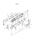
- a movement guide 18 may be installed at the inner side of each frame 12, as illustrated in FIGS. 4 and 5 .
- the movement guides 18 may be installed at the inner sides of the frames 12 to be vertically movable, and the first guide rail 16 may be installed at the inner side of the movement guide 18.
- the developing tray 35 are allowed to move horizontally though the first guide rails 16 and the second guide rails 35e, are allowed to move vertically together with the movement guide 18 according to vertical movement of the movement guide 18.
- an engagement link 19 may be installed between the cover 11 and the movement guide 18.
- Two engagement links 19 may be provided to correspond to the two movement guides 18.
- One end of each engagement link 19 is installed at one side of the inner surface of the cover 11, and the other end of each engagement link 19 may be pivotably installed at a corresponding one of the two frames 12 of the body 10 such that the cover 11 may be pivotably installed at the body 10a.
- An engagement portion 19a protruding toward the corresponding movement guide 18 is provided in the middle of each engagement link 19, and an engagement projection 19b installed at the corresponding movement guide 18 to be vertically movable is formed at the engagement portion 19a.
- An engagement slot 18a at which the engagement projection 19b is installed to be vertically movable, may be provided at one end of the corresponding movement guide 18 proximate to the cover 11 with the longitudinal direction of the engagement slot 18a arranged vertically. Accordingly, the movement guides 18 move horizontally within a specific interval according to the opening and closing operation of the cover 11.
- each of the two frames 12 may be provided with a plurality of guide slots 12a and guide members 18b are installed at each movement guide 18 such that they are respectively fixed at positions corresponding to the guide slots 12a and disposed in the guide slots 12a.
- each of the guide slots 12a includes a first guide section 12a-1, which extends horizontally and guides downward movement of the movement guides 18, a second guide section 12a-2, which extends horizontally and is formed at a higher position than the first guide section 12a-1 to guide upward movement of the movement guides 18, and an inclined section 12a-3, which extends to connect the first guide section 12a-1 and the second guide section 12a-2.
- the image forming apparatus includes a pressing unit 70 to press the developing units 30C, 30M, 30Y and 30K downward to ensure that the lower ends of the developing units 30C, 30M, 30Y and 30K remain stably seated at the seating grooves 17a.
- the pressing unit 70 which is configured to operate in connection with movement of one of the two movement guides 18, includes a pressing housing 71 forming an outer appearance of the pressing unit 70 and fixed to one of the frames 12, a pressing frame 72 installed in the pressing housing 71 to be vertically movable such that the pressing frame 72 moves up or down according to opening or closing of the cover 11 and movement of the movement guide 18, a plurality of pressing members 73 installed at the pressing housing 71 to be vertically movable and having lower ends pressing the developing units 30C, 30M, 30Y and 30K downward, a plurality of elastic members 74 to elastically support the respective support members 73 downward, and a plurality of raising and lowering links 75, 76 and 77 to rotate according to movement of the movement guide 18 to raise or lower the pressing frame 72.
- the plurality of raising and lowering links 75, 76 and 77 includes a first raising and lowering link 75 to transfer force to one end of the pressing frame 72, and a second raising and lowering link 76 and a third raising and lowering link 77 to transfer force to the other end of the pressing frame 72.
- the first raising and lowering link 75 which may be formed to have a V shape and has a middle portion rotationally installed at the pressing housing 71, includes a first cam portion 75a supported by an upper end of the corresponding movement guide 18, and a first hinge portion pivotably installed at one end of the pressing frame 72.
- the second raising and lowering link 76 which may be formed to have a V shape and has a middle portion rotationally installed at the pressing housing 71, includes a second cam 76a supported by the upper end of the corresponding movement guide 18, and a first connecting portion 76b to which the third raising and lowering link 77 is pivotably connected.
- the third raising and lowering link 77 which is formed to have a shape of a bar and has a middle portion rotationally installed at the pressing housing 71, includes a second connecting portion 77a pivotably connected to the first connecting portion 76b, and a second hinge 77b pivotably installed at the other end of the pressing frame 72.
- the movement guide 18 is provided, on an upper end thereof, a first cam surface 18c to interact with the first cam portion 75a, and a second cam surface 18d to interact with the second cam portion 76a.
- An exemplary operation of an image forming apparatus is disclosed.
- the movement guide 18 receives the force transferred from the cover 11 through the engagement projection 19b and the engagement slot 18a and moves toward the opening 10c as the opening 10c is opened, as illustrated in FIG. 8 .
- the movement guide 18 moves upward as the guide member 18b moves from the first guide section 12a-1 to the second guide section 12a-2 through the inclined section 12a-3.
- the developing tray 35 and the developing units 30C, 30M, 30Y and 30K mounted to the developing tray 35 move upward, and the lower ends of the developing units 30C, 30M, 30Y and 30K are detached from the seating grooves 17a.
- the first raising and lowering link 75 and the second raising and lowering link 76 supported by the first cam surface 18c and the second cam surface 18d of the movement guide 18 through the first cam portion 75a and the second cam portion 76a rotate in one direction according to movement of the movement guide 18.
- the pressing frame 72 moves upward, and the lower ends of the pressing members 73 installed at the pressing frame 72 are separated from the upper surfaces of the developing units 30C, 30M, 30Y and 30K.
- the movement guide 18 receives force transferred from the cover 11 through the engagement projection 19b and the engagement slot 18a and moves into the body 10 as the opening 10c is closed, as illustrated in FIG. 7 . Thereby, the movement guide 18 moves downward as the guide member 18b moves from the second guide section 12a-2 to the first guide section 12a-1 through the inclined section 12a-3.
- the developing tray 35 and the developing units 30C, 30M, 30Y and 30K mounted to the developing tray 35 move downward, and the lower ends of the developing units 30C, 30M, 30Y and 30K are seated at the seating grooves 17a.
- the first raising and lowering link 75 and the second raising and lowering link 76 supported by the first cam portion surface 18c and the second cam surface 18d of the movement guide 18 through the first cam portion 75a and the second cam portion 76a rotate in the opposite direction according to movement of the movement guide 18.
- the pressing frame 72 moves downward, and the lower ends of the pressing members 73 installed at the pressing frame 72 contact the upper surfaces of the developing units 30C, 30M, 30Y and 30K to press the developing units 30C, 30M, 30Y and 30K downward.
- the seating grooves 17a may be arranged at the seating member 17 and may be manufactured separately from the frame 12 and mounted to the frame 12, but the embodiments of the present invention are not limited thereto.
- the form of the frame 12 may be changed to integrate the seating member 17 into the frame 12.
- the projection 12b may be arranged at the frame 12, while the protruding portions 34a may be arranged at the developing housing, but the embodiments of the present invention are not limited thereto.
- the projection may be arranged at the developing housing and the protruding portions arranged at the frame.
- the developing units may be supported by being seated at seating grooves provided at the frames in the body, and therefore the positions of the photosensitive bodies of the developing units with respect to other constituents supported by the frames may be accurately regulated, and thereby a uniform image quality may be obtained.
Landscapes
- Physics & Mathematics (AREA)
- General Physics & Mathematics (AREA)
- Engineering & Computer Science (AREA)
- Computer Vision & Pattern Recognition (AREA)
- Electrophotography Configuration And Component (AREA)
Abstract
Description
- Embodiments of the present invention relate to an image forming apparatus equipped with a development tray movably installed on a body and provided with a development unit.
- Generally, an image forming apparatus forms an image on a printing medium. Examples of such an image forming apparatus include a printer, a copier, a facsimile machine, and a complex machine having functions of the one or more apparatuses.
- An image forming apparatus includes a body provided, at one side thereof, with an opening, a plurality of developing units disposed in the body, each of the developing units capable of developing an electrostatic latent image into a visible image using a corresponding one of developing agents of different colors, an exposure device to scan light onto photosensitive bodies of the development units and thus to form an electrostatic latent image on the photosensitive body of each development unit, a transfer device to transfer the visible image developed using the corresponding developing agent to a printing medium, and a fusing device to fuse the developing agents of the visible image to the printing medium.
- A type of image forming apparatus has a plurality of developing units installed in a developing tray movably installed in an opening formed at one side of a body, to easily and conveniently replace developing units whose developing agents have been consumed.
- It is an aspect of the present invention to provide an image forming apparatus that allows developing units to be more accurately installed through a developing tray in a body of the apparatus.
- Additional aspects of the invention will be set forth in part in the description which follows and, in part, will be obvious from the description, or may be learned by practice of the invention.
- In accordance with an aspect of the present invention, an image forming apparatus includes a body provided with an opening at a side thereof, a developing tray movably installed at the opening, a plurality of developing units mounted to the developing tray, a plurality of, for example, a pair of frames forming opposite inner sides of the body, and a plurality of seating grooves provided in the frames to support lower ends of the plurality of developing units.
- The image forming apparatus includes a plurality of seating members, each of which is provided with a plurality of seating grooves on an upper side thereof and disposed at a corresponding one of the plurality of the frames.
- Each of the seating members may be integrated into the corresponding one of the frames.
- Each of the seating grooves may be open upward and formed to have a V shape.
- Each of the developing units includes a developing housing forming an outer appearance thereof, wherein the developing housing includes a plurality of, for example, a pair of protruding portions disposed at an upper portion of one side of the developing housing and spaced from each other, and a corresponding one of the frames includes a projection which is supported between the plurality of protruding portions.
- The image forming apparatus includes a cover pivotably installed at the body to rotate about a lower end of the cover to open and close the opening, a plurality of, for example, a pair of movement guides allowing the developing tray to be installed thereon to be horizontally movable, and installed respectively at the pair of frames to be vertically movable, a plurality of engagement links to move the movement guides according to opening and closing of the cover, and a plurality of guide members installed at the movement guides to allow the movement guides to be movably installed at the frames, wherein each of the frames includes a plurality of guide slots in which the guide members are movably installed.
- Each of the guide slots includes a first guide section to guide downward movement of a corresponding one of the movement guides, a second guide section formed at a higher position than the first section to guide upward movement of the corresponding one of the movement guides, and an inclined section formed to be inclined to connect the first guide section and the second guide section.
- Each of the engagement links includes an engagement portion protruding toward a corresponding one of the movement guides, and an engagement projection arranged at the engagement portion, wherein the corresponding one of the movement guides includes an engagement slot extending vertically to allow the engagement projection to be installed therein to be vertically movable.
- The image forming apparatus includes a pressing unit to press the developing units downward in connection with movement of the movement guides.
- The pressing unit includes a pressing housing forming an outer appearance of the pressing unit and installed at one of the frames, a pressing frame installed in the pressing housing to be vertically movable, at least one pressing member installed at the pressing frame to be vertically movable, and at least one elastic member to elastically support the at least one pressing member downward.
- The pressing unit further includes a plurality of raising and lowering links rotatably installed at the pressing housing such that the pressing frame is raised or lowered in connection with movement of the movement guides as the plurality of raising and lowering links rotates.
- The plurality of raising and lowering links includes a first raising and lowering link to transfer force to an end of the pressing frame, and a second raising and lowering link and a third raising and lowering link to transfer the force to the other end of the pressing frame, wherein the first raising and lowering link includes a first cam portion supported by a corresponding one of the movement guides, and a first hinge portion pivotably installed at an end of the pressing frame, the second raising and lowering link includes a second cam supported by the corresponding one of the movement guides, and a first connecting portion connected with the third raising and lowering link, the third raising and lowering link includes a second connecting portion pivotably connected to the first connecting portion, and a second hinge pivotably installed at the other end of the pressing frame, and the corresponding one of the movement guides includes a first cam surface to interact with the first cam portion, and a second cam surface to interact with the second cam portion.
- In accordance with an aspect of the present invention, an image forming apparatus includes a body provided with an opening at one side thereof, a developing tray movably installed at the opening, a plurality of developing units mounted to the developing tray, a plurality of, for example, a pair of frames forming opposite inner sides of the body, a cover pivotably installed at the body to rotate about a lower end of the cover to open and close the opening, and a pressing unit to press the developing units downward in connection with opening and closing of the cover.
- In accordance with an aspect of the present invention, an image forming apparatus includes a body provided with an opening, a frame disposed in the body, a developing tray movably installed at the frame to enter and come out of the body through the opening, a plurality of developing units configured to contain developing agents and detachably mounted to the developing tray, each of the developing units including a developing housing having a side facing the frame, a plurality of projections protruding from one of the side of the developing housing and the frame to respectively correspond to the developing units, and a plurality of protruding portions provided at the other side of the developing housing and the frame to respectively correspond to the projections, each of the protruding portions restricting a corresponding one of the projections to limit movement of a corresponding one of the developing units.
- The plurality of the protruding portions includes a plurality of, for example, a pair of protruding portions corresponding to one of the projections and disposed to be spaced from each other, wherein the corresponding one of the projections may be supported between the pair of the protruding portions.
- The plurality of the developing units may be arranged in cascade, and the pair of the protruding portions may be disposed to support front and rear sides of the corresponding one of the projections.
- The plurality of the projections may be disposed at the frame, and each of the plurality of the protruding portions may be disposed at the developing housing of a corresponding one of the developing units.
- Each of the developing units further may include a photosensitive body rotatably supported by a lower end thereof, and each of the plurality of the protruding portions may be disposed to limit movement of an upper end of a corresponding one of the developing units.
- The image forming apparatus includes a plurality of seating grooves provided at the frame to respectively support lower ends of the plurality of developing units.
- In accordance with an aspect of the present invention, a developing unit mountable to a body of an image forming apparatus through a developing tray movably installed at a frame includes a developing housing having a side facing the frame when the developing unit is mounted to the image forming apparatus, and at least one protruding portion provided at the side of the developing housing such that when the developing unit is mounted to the image forming apparatus, the at least one protruding portion is coupled with a projection provided at the frame to limit movement of the developing unit.
- The developing unit may include a photosensitive body rotatably installed at a lower end of the developing housing, wherein the at least one protruding portion may be disposed at an upper end of the developing housing.
- The at least one protruding portion may include a plurality of, for example, a pair of protruding portions disposed to be spaced from each other to support opposite sides of the projection provided at the frame.
- The at least one protruding portion may be arranged at an upper end of the side of the developing housing to limit movement of an upper end of the developing housing, and a lower end of the developing housing may be supported by a seating groove provided at the frame when the developing housing is mounted to the image forming apparatus.
- These and/or other aspects of the invention will become apparent and more readily appreciated from the following description of the embodiments, taken in conjunction with the accompanying drawings of which:
-
FIG. 1 illustrates an image forming apparatus according to an exemplary embodiment of the present invention; -
FIG. 2 illustrates developing units and a developing tray to which the developing units are mounted, according to an exemplary embodiment of the present invention; -
FIG. 3 illustrates developing units mounted in a body of an image forming apparatus according to an exemplary embodiment of the present invention; -
FIGS. 4 and5 illustrate a movement guide installed at a frame and a pressing unit, in accordance with an exemplary embodiment of the present invention; -
FIG. 6 illustrates a guide slot provided at a frame in accordance with an exemplary embodiment of the present invention; -
FIGS. 7 and8 illustrate exemplary operations of the movement guide and the developing unit operating in connection with a cover, in accordance with an exemplary embodiment of the present invention; and -
FIGS. 9 and10 illustrate an exemplary operation of the pressing unit operating in connection with the cover, in accordance with an exemplary embodiment of the present invention. - Reference will now be made in detail to the embodiments of the present invention, examples of which are illustrated in the accompanying drawings, wherein like reference numerals refer to like elements throughout.
- As illustrated in
FIG. 1 , the image forming apparatus according to an exemplary embodiment of the present invention includes abody 10 to define an outer appearance of the apparatus, a printingmedium storage unit 20 to store printing mediums therein, a plurality of developingunits exposure unit 40 to scan light ontophotosensitive bodies 31 of the developingunits photosensitive body 31, atransfer unit 50 to receive printing medium from the printingmedium storage unit 20 and transfer a visible image formed on eachphotosensitive body 31 to the printing medium, and afusing unit 60 to fuse, to the printing medium, the developing agent of the visible image transferred to the printing medium. - The
body 10 may be provided, at a top thereof, with astacking section 10a, on which printing mediums having completed image formation are stacked. Thestacking section 10a may be provided, at a side thereof, with adischarge port 10b, through which printing mediums having completed image formation are discharged. Thebody 10 includes, at a side thereof, an opening 10c through which inner components including the developingunits cover 11 pivotably installed at thebody 10, to open or close the opening 10c when rotated. - The printing
medium storage unit 20 includes aprinting medium cassette 21 movably mounted to thebody 10, a knock-up plate 22 disposed in theprinting medium cassette 21, to stack printing mediums thereon, and anelastic member 23 to elastically support the knock-upplate 22. - Each of the developing
units photosensitive body 31. On a charged surface of thephotosensitive body 31, an electrostatic latent image may be formed by theexposure unit 40. Each of the developingunits roller 32 to supply the corresponding developing agent to thephotosensitive body 31, acharging roller 33 to charge the surface of thephotosensitive body 31, and a developinghousing 34 to form an outer appearance of the corresponding developingunit photosensitive body 31, the developingroller 32 and thecharging roller 33. - Each of the developing
units units units transfer unit 50. - The
exposure unit 40 irradiates light carrying image information onto thephotosensitive bodies 31 provided at respective developingunits photosensitive body 31. - The
transfer unit 50 includes atransfer belt 51, to which the developing agents used to develop electrostatic latent images on respectivephotosensitive bodies 31 of the developingunits drive roller 52 and a drivenroller 53, which may be disposed inside thetransfer belt 51 at opposite sides of thetransfer unit 50, respectively, to rotate thetransfer belt 51, a plurality offirst transfer rollers 54 disposed to face respectivephotosensitive bodies 31 of the developingunits transfer belt 51 interposed between eachfirst transfer roller 54 and the correspondingphotosensitive body 31, to transfer visible images formed on respectivephotosensitive bodies 31 to thetransfer belt 51, and asecond transfer roller 55 disposed to face the drivenroller 53 with thetransfer belt 51 interposed between thesecond transfer roller 55 and the drivenroller 53, to transfer the visible images on thetransfer belt 51 to the printing medium fed to thesecond transfer roller 55. - The
fusing unit 60 includes aheating roller 61 to generate heat, and apressing roller 62 having an outer circumferential surface made of an elastically deformable material, to press the printing medium against an outer circumferential surface of theheating roller 61. - The
body 10 includes a pick-up roller 13 disposed over the printingmedium storage unit 20, to pick up, , for example, one-by-one, the printing mediums stacked on the knock-upplate 22, a feeding roller 14 to upwardly guide the printing medium picked up by the pick-up roller 13, and adischarge roller 15 disposed adjacent to thedischarge port 10b above thefusing unit 60, to discharge the printing medium emerging from thefusing unit 60 through thedischarge port 10b. - As illustrated in
FIG. 2 , thebody 10 may be provided with a plurality of, for example, a pair offrames 12 disposed in thebody 10, to form opposite inner sides of thebody 10 and support the inner components of the image forming apparatus. Theframes 12 may be made of a metallic material having sufficient strength to support the inner components of the image forming apparatus. - Developing
units - Accordingly, a developing
tray 35 may be movably installed at theopening 10c, for installation of the developingunits units 30C, 30Mf, 30Y and 30K may be mounted to the developingtray 35 in turn such that when the developingtray 35 moves into thebody 10 through theopening 10c, the developingunits body 10, and when the developingtray 35 moves outside thebody 10 through theopening 10c, the developingunits body 10. The developingunits body 10 to the rear side thereof at the developingtray 35, and the developingtray 35 may be movable forward or backward to enter or come out of thebody 10. - The developing
tray 35 includes atray section 35a, to which the developingunits handle 35b provided at one end of thetray section 35a, to allow a user to easily apply force to the developingtray 35. Alternately provided on a lower surface of thetray section 35a are throughholes 35c to allow thephotosensitive bodies 31 respectively provided at the developingunits tray section 35a to contact thetransfer belt 51 disposed under thetray section 35a, and supports 35d to support the lower ends of the developingunits units tray section 35a. -
First guide rails 16 at which the developingtray 35 may be movably installed are respectively installed at inner sides of theframes 12 such that the developingtray 35 is movably installed in thebody 10, and second guide rails 35e movably installed at thefirst guide rails 16 may be respectively installed on the opposite sides of thetray section 35a of the developingtray 35. - Provided in the
body 10 areseats 17a to regulate positions of the developingunits tray 35. According to an exemplary embodiment, a plurality ofseating grooves 17a are arranged in parallel on top of each seatingmember 17 installed at thecorresponding frame 12. Accordingly, the lower ends of the developingunits seating grooves 17a. As illustrated inFIG. 3 , theseating grooves 17a of the present embodiment are formed to be open upward and have a V-shaped cross section. - When the lower ends of the developing
units seating grooves 17a of theseating members 17 fixed to theframes 12 as above, relative positions of thephotosensitive bodies 31 with respect to other components supported by theframes 12, especially thetransfer belt 51 facing thephotosensitive bodies 31 or the first transfer rollers, may be precisely regulated, and thereby a uniform image quality may be obtained. - With the developing
units seating grooves 17a, the developingunits units units portions 34a disposed on one side of the developinghousing 34 to be spaced from each other, and acorresponding projection 12b is disposed at theframe 12 to be stuck between the two protrudingportions 34a to prevent rotation of the developinghousing 34 with each of the developingunits corresponding seating groove 17a. - In order for the lower ends of the developing
units seating grooves 17a, the developingunits tray 35 equipped with the developingunits cover 11 to move the developingunits opening 10c is opened by thecover 11, the developingtray 35 moves upward and thus the lower ends of the developingunits tray 35 are detached from theseating grooves 17a. When theopening 10c is closed by thecover 11, the developingtray 35 moves downward and thus the lower ends of the developingunits tray 35 are seated at theseating grooves 17a. - To allow the developing
tray 35 to be vertically movable in connection with thecover 11 as above, amovement guide 18 may be installed at the inner side of eachframe 12, as illustrated inFIGS. 4 and5 . The movement guides 18 may be installed at the inner sides of theframes 12 to be vertically movable, and thefirst guide rail 16 may be installed at the inner side of themovement guide 18. The developingtray 35 are allowed to move horizontally though thefirst guide rails 16 and the second guide rails 35e, are allowed to move vertically together with themovement guide 18 according to vertical movement of themovement guide 18. - To make the
movement guide 18 operate in connection with thecover 11, anengagement link 19 may be installed between thecover 11 and themovement guide 18. Twoengagement links 19 may be provided to correspond to the two movement guides 18. One end of eachengagement link 19 is installed at one side of the inner surface of thecover 11, and the other end of eachengagement link 19 may be pivotably installed at a corresponding one of the twoframes 12 of thebody 10 such that thecover 11 may be pivotably installed at thebody 10a. Anengagement portion 19a protruding toward the correspondingmovement guide 18 is provided in the middle of eachengagement link 19, and anengagement projection 19b installed at thecorresponding movement guide 18 to be vertically movable is formed at theengagement portion 19a. Anengagement slot 18a, at which theengagement projection 19b is installed to be vertically movable, may be provided at one end of thecorresponding movement guide 18 proximate to thecover 11 with the longitudinal direction of theengagement slot 18a arranged vertically. Accordingly, the movement guides 18 move horizontally within a specific interval according to the opening and closing operation of thecover 11. - To allow the movement guides 18 to move vertically as they move horizontally, each of the two
frames 12 may be provided with a plurality ofguide slots 12a and guidemembers 18b are installed at each movement guide 18 such that they are respectively fixed at positions corresponding to theguide slots 12a and disposed in theguide slots 12a. - As illustrated in
FIG. 6 , each of theguide slots 12a includes afirst guide section 12a-1, which extends horizontally and guides downward movement of the movement guides 18, asecond guide section 12a-2, which extends horizontally and is formed at a higher position than thefirst guide section 12a-1 to guide upward movement of the movement guides 18, and aninclined section 12a-3, which extends to connect thefirst guide section 12a-1 and thesecond guide section 12a-2. - As illustrated in
FIG. 5 , the image forming apparatus includes apressing unit 70 to press the developingunits units seating grooves 17a. - The
pressing unit 70, which is configured to operate in connection with movement of one of the two movement guides 18, includes apressing housing 71 forming an outer appearance of thepressing unit 70 and fixed to one of theframes 12, apressing frame 72 installed in thepressing housing 71 to be vertically movable such that thepressing frame 72 moves up or down according to opening or closing of thecover 11 and movement of themovement guide 18, a plurality of pressingmembers 73 installed at thepressing housing 71 to be vertically movable and having lower ends pressing the developingunits elastic members 74 to elastically support therespective support members 73 downward, and a plurality of raising and loweringlinks movement guide 18 to raise or lower thepressing frame 72. - The plurality of raising and lowering
links link 75 to transfer force to one end of thepressing frame 72, and a second raising and loweringlink 76 and a third raising and loweringlink 77 to transfer force to the other end of thepressing frame 72. - The first raising and lowering
link 75, which may be formed to have a V shape and has a middle portion rotationally installed at thepressing housing 71, includes afirst cam portion 75a supported by an upper end of thecorresponding movement guide 18, and a first hinge portion pivotably installed at one end of thepressing frame 72. The second raising and loweringlink 76, which may be formed to have a V shape and has a middle portion rotationally installed at thepressing housing 71, includes asecond cam 76a supported by the upper end of thecorresponding movement guide 18, and a first connectingportion 76b to which the third raising and loweringlink 77 is pivotably connected. The third raising and loweringlink 77, which is formed to have a shape of a bar and has a middle portion rotationally installed at thepressing housing 71, includes a second connectingportion 77a pivotably connected to the first connectingportion 76b, and asecond hinge 77b pivotably installed at the other end of thepressing frame 72. - The
movement guide 18 is provided, on an upper end thereof, afirst cam surface 18c to interact with thefirst cam portion 75a, and asecond cam surface 18d to interact with thesecond cam portion 76a. - An exemplary operation of an image forming apparatus is disclosed.
- If the user applies force to the
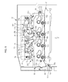
cover 11 to open theopening 10c when theopening 10c is closed by thecover 11 as illustrated inFIG. 7 , themovement guide 18 receives the force transferred from thecover 11 through theengagement projection 19b and theengagement slot 18a and moves toward theopening 10c as theopening 10c is opened, as illustrated inFIG. 8 . Thereby, themovement guide 18 moves upward as theguide member 18b moves from thefirst guide section 12a-1 to thesecond guide section 12a-2 through theinclined section 12a-3. The developingtray 35 and the developingunits tray 35 move upward, and the lower ends of the developingunits seating grooves 17a. - As illustrated in
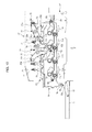
FIG. 9 , the first raising and loweringlink 75 and the second raising and loweringlink 76 supported by thefirst cam surface 18c and thesecond cam surface 18d of themovement guide 18 through thefirst cam portion 75a and thesecond cam portion 76a rotate in one direction according to movement of themovement guide 18. Thereby, as illustrated inFIG. 10 , thepressing frame 72 moves upward, and the lower ends of thepressing members 73 installed at thepressing frame 72 are separated from the upper surfaces of the developingunits - If the user applies force to the
cover 11 to close theopening 10c when theopening 10c is opened by thecover 11 as illustrated inFIG. 8 , themovement guide 18 receives force transferred from thecover 11 through theengagement projection 19b and theengagement slot 18a and moves into thebody 10 as theopening 10c is closed, as illustrated inFIG. 7 . Thereby, themovement guide 18 moves downward as theguide member 18b moves from thesecond guide section 12a-2 to thefirst guide section 12a-1 through theinclined section 12a-3. The developingtray 35 and the developingunits tray 35 move downward, and the lower ends of the developingunits seating grooves 17a. - As illustrated in
FIG. 10 , the first raising and loweringlink 75 and the second raising and loweringlink 76 supported by the firstcam portion surface 18c and thesecond cam surface 18d of themovement guide 18 through thefirst cam portion 75a and thesecond cam portion 76a rotate in the opposite direction according to movement of themovement guide 18. Thereby, as illustrated inFIG. 9 , thepressing frame 72 moves downward, and the lower ends of thepressing members 73 installed at thepressing frame 72 contact the upper surfaces of the developingunits units - According to an exemplary embodiment, the
seating grooves 17a may be arranged at the seatingmember 17 and may be manufactured separately from theframe 12 and mounted to theframe 12, but the embodiments of the present invention are not limited thereto. The form of theframe 12 may be changed to integrate the seatingmember 17 into theframe 12. According to an exemplary embodiment, theprojection 12b may be arranged at theframe 12, while the protrudingportions 34a may be arranged at the developing housing, but the embodiments of the present invention are not limited thereto. The projection may be arranged at the developing housing and the protruding portions arranged at the frame. - The developing units may be supported by being seated at seating grooves provided at the frames in the body, and therefore the positions of the photosensitive bodies of the developing units with respect to other constituents supported by the frames may be accurately regulated, and thereby a uniform image quality may be obtained.
- Although a few embodiments of the present invention have been shown and described, it would be appreciated by those skilled in the art that changes may be made in these embodiments without departing from the principles and spirit of the invention, the scope of which is defined in the claims and their equivalents.
Claims (12)
- An image forming apparatus comprising:a body (10) provided with an opening (10c) at a side thereof;a developing tray (35) movably installed at the opening (10c);a plurality of developing units (35) mounted to the developing tray (35);a pair of frames (12) forming opposite inner sides of the body (10); anda plurality of seating grooves (17a) provided in the frames (12) to support lower ends of the plurality of developing units (30).
- The image forming apparatus according to claim 1, further comprising a plurality of seating members (17), each of which is provided with a plurality of seating grooves (17a) on an upper side thereof and disposed at a corresponding one of the pair of the frames (12).
- The image forming apparatus according to claim 2, wherein each of the seating members (17) is integrated into the corresponding one of the frames (12).
- The image forming apparatus according to claim 1, wherein each of the seating grooves (17a) is open upward and formed to have a V shape.
- The image forming apparatus according to claim 2, wherein each of the developing units (30) includes a developing housing (34) forming an outer appearance thereof,
wherein:the developing housing (34) includes a pair of protruding portions disposed at an upper portion of one side of the developing housing (34) and spaced from each other; anda corresponding one of the frames (12) includes a projection (12b) which is supported between the pair of protruding portions (34a). - The image forming apparatus according to claim 2, further comprising:a cover (11) pivotably installed at the body (10) to rotate about a lower end of the cover (11) to open and close the opening (10c);a pair of movement guides (18) allowing the developing tray (35) to be installed thereon to be horizontally movable, and installed respectively at the pair of frames (12) to be vertically movable;a plurality of engagement links (19) to move the movement guides (18) according to opening and closing of the cover (11); anda plurality of guide members (18b) installed at the movement guides (18) to allow the movement guides (18b) to be movably installed at the frames (12),wherein each of the frames (12) includes a plurality of guide slots (12a) in which the guide members (18b) are movably installed.
- The image forming apparatus according to claim 6, wherein each of the guide slots (12a) includes a first guide section (12a-1) to guide downward movement of a corresponding one of the movement guides (18), a second guide section (12a-2) formed at a higher position than the first guide section (12a-1) to guide upward movement of the corresponding one of the movement guides (18), and an inclined section (12a-3) formed to be inclined to connect the first guide section (12a-1) and the second guide section (12a-2).
- The image forming apparatus according to claim 6, wherein each of the engagement links (19) includes an engagement portion (19a) protruding toward a corresponding one of the movement guides (18), and an engagement projection (19b) arranged at the engagement portion (19a),
wherein the corresponding one of the movement guides (18) includes an engagement slot (18a) extending vertically to allow the engagement projection (19b_ to be installed therein to be vertically movable. - The image forming apparatus according to claim 7, further comprising a pressing unit (70) to press the developing units (30) downward in connection with movement of the movement guides (18).
- The image forming apparatus according to claim 9, wherein the pressing unit (70) includes a pressing housing (71) forming an outer appearance of the pressing unit (70) and installed at one of the frames (12), a pressing frame (72) installed in the pressing housing (71) to be vertically movable, at least one pressing member (73) installed at the pressing frame (72) to be vertically movable, and at least one elastic member (74) to elastically support the at least one pressing member (73) downward.
- The image forming apparatus according to claim 10, wherein the pressing unit (70) further includes a plurality of raising and lowering links (75, 76, 77) rotatably installed at the pressing housing (71) such that the pressing frame (72) is raised or lowered in connection with movement of the movement guides (18) as the plurality of raising and lowering links (75, 76, 77) rotates.
- The image forming apparatus according to claim 11, wherein the plurality of raising and lowering links (75, 76, 77) includes a first raising and lowering link (75) to transfer force to one end of the pressing frame (72), and a second raising and lowering link (76) and a third raising and lowering link (77) to transfer the force to the other end of the pressing frame (72),
wherein:the first raising and lowering link (75) includes a first cam portion (75a) supported by a corresponding one of the movement guides (18), and a first hinge portion pivotably installed at one end of the pressing frame (72);the second raising and lowering link (76) includes a second cam (76a) supported by the corresponding one of the movement guides (18), and a first connecting portion (76b) connected with the third raising and lowering link (77);the third raising and lowering link (77) includes a second connecting portion (77a) pivotably connected to the first connecting portion (76a), and a second hinge pivotably installed at the other end of the pressing frame (72); andthe corresponding one of the movement guides (18) includes a first cam surface (18c) to interact with the first cam portion (75a), and a second cam surface (18d) to interact with the second cam portion (76a).
Applications Claiming Priority (1)
| Application Number | Priority Date | Filing Date | Title |
|---|---|---|---|
| KR1020110135427A KR101520259B1 (en) | 2011-12-15 | 2011-12-15 | Image forming apparatus |
Publications (3)
| Publication Number | Publication Date |
|---|---|
| EP2605077A2 true EP2605077A2 (en) | 2013-06-19 |
| EP2605077A3 EP2605077A3 (en) | 2013-12-18 |
| EP2605077B1 EP2605077B1 (en) | 2016-08-31 |
Family
ID=47598626
Family Applications (1)
| Application Number | Title | Priority Date | Filing Date |
|---|---|---|---|
| EP12197327.5A Not-in-force EP2605077B1 (en) | 2011-12-15 | 2012-12-14 | Image forming apparatus |
Country Status (3)
| Country | Link |
|---|---|
| US (1) | US9152075B2 (en) |
| EP (1) | EP2605077B1 (en) |
| KR (1) | KR101520259B1 (en) |
Families Citing this family (16)
| Publication number | Priority date | Publication date | Assignee | Title |
|---|---|---|---|---|
| GB2522520B (en) * | 2012-11-28 | 2016-02-24 | Canon Kk | Image forming apparatus |
| JP6065650B2 (en) | 2013-02-28 | 2017-01-25 | ブラザー工業株式会社 | Image forming apparatus |
| JP6541403B2 (en) * | 2014-05-14 | 2019-07-10 | キヤノン株式会社 | Image forming device |
| JP6577274B2 (en) * | 2014-07-17 | 2019-09-18 | 株式会社沖データ | Image forming apparatus |
| JP6602051B2 (en) * | 2015-05-27 | 2019-11-06 | キヤノン株式会社 | Image forming apparatus |
| JP6299680B2 (en) * | 2015-06-15 | 2018-03-28 | 京セラドキュメントソリューションズ株式会社 | Image forming apparatus |
| JP6540579B2 (en) * | 2015-06-26 | 2019-07-10 | 京セラドキュメントソリューションズ株式会社 | Image forming device |
| JP6566748B2 (en) * | 2015-07-01 | 2019-08-28 | キヤノン株式会社 | Image forming apparatus |
| KR20170008417A (en) * | 2015-07-14 | 2017-01-24 | 에스프린팅솔루션 주식회사 | Auto locking device and image forming apparatus having the same |
| JP6736402B2 (en) * | 2016-07-22 | 2020-08-05 | キヤノン株式会社 | Image forming device |
| US10241465B2 (en) * | 2016-09-26 | 2019-03-26 | Fuji Xerox Co., Ltd. | Opening and closing mechanism and image forming apparatus |
| JP6946628B2 (en) * | 2016-09-30 | 2021-10-06 | ブラザー工業株式会社 | Image forming device |
| JP6455845B2 (en) * | 2016-11-07 | 2019-01-23 | キヤノン株式会社 | Electrophotographic image forming apparatus and photoreceptor unit |
| JP7039226B2 (en) | 2017-09-21 | 2022-03-22 | キヤノン株式会社 | Developer replenishment container and developer replenishment system |
| JP7259603B2 (en) * | 2019-07-10 | 2023-04-18 | ブラザー工業株式会社 | image forming device |
| JP7686467B2 (en) * | 2021-06-17 | 2025-06-02 | キヤノン株式会社 | Image forming device |
Family Cites Families (5)
| Publication number | Priority date | Publication date | Assignee | Title |
|---|---|---|---|---|
| JP5084257B2 (en) * | 2006-12-28 | 2012-11-28 | キヤノン株式会社 | Process cartridge and image forming apparatus using the same |
| JP4280772B2 (en) * | 2006-12-28 | 2009-06-17 | キヤノン株式会社 | Process cartridge and electrophotographic image forming apparatus |
| JP5414171B2 (en) * | 2007-11-21 | 2014-02-12 | キヤノン株式会社 | Image forming apparatus |
| JP5029388B2 (en) * | 2008-01-24 | 2012-09-19 | ブラザー工業株式会社 | Image forming apparatus |
| JP4372214B1 (en) * | 2008-09-29 | 2009-11-25 | キヤノン株式会社 | Color electrophotographic image forming apparatus |
-
2011
- 2011-12-15 KR KR1020110135427A patent/KR101520259B1/en not_active Expired - Fee Related
-
2012
- 2012-12-14 US US13/714,902 patent/US9152075B2/en active Active
- 2012-12-14 EP EP12197327.5A patent/EP2605077B1/en not_active Not-in-force
Non-Patent Citations (1)
| Title |
|---|
| None |
Also Published As
| Publication number | Publication date |
|---|---|
| KR101520259B1 (en) | 2015-05-18 |
| EP2605077A3 (en) | 2013-12-18 |
| KR20130068086A (en) | 2013-06-25 |
| US9152075B2 (en) | 2015-10-06 |
| EP2605077B1 (en) | 2016-08-31 |
| US20130156463A1 (en) | 2013-06-20 |
Similar Documents
| Publication | Publication Date | Title |
|---|---|---|
| EP2605077B1 (en) | Image forming apparatus | |
| US8380103B2 (en) | Image forming apparatus having photosensitive member unit that moves between an outer position and an operational position | |
| CN106909044B (en) | Image forming apparatus with a plurality of image forming units | |
| RU2419121C2 (en) | Image forming electrophotographic apparatus | |
| US8837982B2 (en) | Electrophotographic image forming apparatus | |
| US8457520B2 (en) | Image forming device having guide mechanism for guiding transferring unit | |
| US8036572B2 (en) | Color electrophotographic image forming apparatus | |
| CN101770193B (en) | Image forming apparatus and developing cartridge | |
| JP5838611B2 (en) | Image forming apparatus | |
| US9195202B2 (en) | Image forming apparatus, and method of transmitting power and method of mounting developing unit in the same | |
| JP5838610B2 (en) | Image forming apparatus | |
| US7606512B2 (en) | Image forming device with cover protrusions | |
| CN101620405A (en) | Image-forming device | |
| KR101766782B1 (en) | Image forming device | |
| JP5805156B2 (en) | Image forming apparatus | |
| US8831475B2 (en) | Image forming apparatus | |
| US10962918B2 (en) | Image forming apparatus having a mountable unit for discharging developer | |
| EP2549336B1 (en) | Image forming apparatus | |
| EP2450751B1 (en) | Image forming apparatus | |
| JP2017032761A (en) | Image forming apparatus | |
| KR20120055431A (en) | Developing cartridge and image forming apparatus having the same | |
| US9061853B2 (en) | Image forming apparatus having process unit and tray | |
| JP5776183B2 (en) | Image forming apparatus | |
| JP7779147B2 (en) | Image forming device | |
| KR20160143292A (en) | Image forming apparatus and control method for the same |
Legal Events
| Date | Code | Title | Description |
|---|---|---|---|
| PUAI | Public reference made under article 153(3) epc to a published international application that has entered the european phase |
Free format text: ORIGINAL CODE: 0009012 |
|
| AK | Designated contracting states |
Kind code of ref document: A2 Designated state(s): AL AT BE BG CH CY CZ DE DK EE ES FI FR GB GR HR HU IE IS IT LI LT LU LV MC MK MT NL NO PL PT RO RS SE SI SK SM TR |
|
| AX | Request for extension of the european patent |
Extension state: BA ME |
|
| RIC1 | Information provided on ipc code assigned before grant |
Ipc: G03G 21/18 20060101AFI20130820BHEP Ipc: G03G 21/16 20060101ALI20130820BHEP |
|
| PUAL | Search report despatched |
Free format text: ORIGINAL CODE: 0009013 |
|
| AK | Designated contracting states |
Kind code of ref document: A3 Designated state(s): AL AT BE BG CH CY CZ DE DK EE ES FI FR GB GR HR HU IE IS IT LI LT LU LV MC MK MT NL NO PL PT RO RS SE SI SK SM TR |
|
| AX | Request for extension of the european patent |
Extension state: BA ME |
|
| RIC1 | Information provided on ipc code assigned before grant |
Ipc: G03G 21/16 20060101ALI20131112BHEP Ipc: G03G 21/18 20060101AFI20131112BHEP |
|
| 17P | Request for examination filed |
Effective date: 20140617 |
|
| RBV | Designated contracting states (corrected) |
Designated state(s): AL AT BE BG CH CY CZ DE DK EE ES FI FR GB GR HR HU IE IS IT LI LT LU LV MC MK MT NL NO PL PT RO RS SE SI SK SM TR |
|
| 17Q | First examination report despatched |
Effective date: 20150323 |
|
| GRAP | Despatch of communication of intention to grant a patent |
Free format text: ORIGINAL CODE: EPIDOSNIGR1 |
|
| INTG | Intention to grant announced |
Effective date: 20160407 |
|
| GRAS | Grant fee paid |
Free format text: ORIGINAL CODE: EPIDOSNIGR3 |
|
| GRAA | (expected) grant |
Free format text: ORIGINAL CODE: 0009210 |
|
| AK | Designated contracting states |
Kind code of ref document: B1 Designated state(s): AL AT BE BG CH CY CZ DE DK EE ES FI FR GB GR HR HU IE IS IT LI LT LU LV MC MK MT NL NO PL PT RO RS SE SI SK SM TR |
|
| REG | Reference to a national code |
Ref country code: CH Ref legal event code: EP Ref country code: GB Ref legal event code: FG4D |
|
| REG | Reference to a national code |
Ref country code: IE Ref legal event code: FG4D |
|
| REG | Reference to a national code |
Ref country code: DE Ref legal event code: R096 Ref document number: 602012022351 Country of ref document: DE |
|
| REG | Reference to a national code |
Ref country code: AT Ref legal event code: REF Ref document number: 825490 Country of ref document: AT Kind code of ref document: T Effective date: 20161015 |
|
| REG | Reference to a national code |
Ref country code: NL Ref legal event code: FP |
|
| REG | Reference to a national code |
Ref country code: LT Ref legal event code: MG4D |
|
| REG | Reference to a national code |
Ref country code: AT Ref legal event code: MK05 Ref document number: 825490 Country of ref document: AT Kind code of ref document: T Effective date: 20160831 |
|
| PG25 | Lapsed in a contracting state [announced via postgrant information from national office to epo] |
Ref country code: FI Free format text: LAPSE BECAUSE OF FAILURE TO SUBMIT A TRANSLATION OF THE DESCRIPTION OR TO PAY THE FEE WITHIN THE PRESCRIBED TIME-LIMIT Effective date: 20160831 Ref country code: LT Free format text: LAPSE BECAUSE OF FAILURE TO SUBMIT A TRANSLATION OF THE DESCRIPTION OR TO PAY THE FEE WITHIN THE PRESCRIBED TIME-LIMIT Effective date: 20160831 Ref country code: NO Free format text: LAPSE BECAUSE OF FAILURE TO SUBMIT A TRANSLATION OF THE DESCRIPTION OR TO PAY THE FEE WITHIN THE PRESCRIBED TIME-LIMIT Effective date: 20161130 Ref country code: RS Free format text: LAPSE BECAUSE OF FAILURE TO SUBMIT A TRANSLATION OF THE DESCRIPTION OR TO PAY THE FEE WITHIN THE PRESCRIBED TIME-LIMIT Effective date: 20160831 Ref country code: HR Free format text: LAPSE BECAUSE OF FAILURE TO SUBMIT A TRANSLATION OF THE DESCRIPTION OR TO PAY THE FEE WITHIN THE PRESCRIBED TIME-LIMIT Effective date: 20160831 |
|
| PG25 | Lapsed in a contracting state [announced via postgrant information from national office to epo] |
Ref country code: LV Free format text: LAPSE BECAUSE OF FAILURE TO SUBMIT A TRANSLATION OF THE DESCRIPTION OR TO PAY THE FEE WITHIN THE PRESCRIBED TIME-LIMIT Effective date: 20160831 Ref country code: SE Free format text: LAPSE BECAUSE OF FAILURE TO SUBMIT A TRANSLATION OF THE DESCRIPTION OR TO PAY THE FEE WITHIN THE PRESCRIBED TIME-LIMIT Effective date: 20160831 Ref country code: ES Free format text: LAPSE BECAUSE OF FAILURE TO SUBMIT A TRANSLATION OF THE DESCRIPTION OR TO PAY THE FEE WITHIN THE PRESCRIBED TIME-LIMIT Effective date: 20160831 Ref country code: AT Free format text: LAPSE BECAUSE OF FAILURE TO SUBMIT A TRANSLATION OF THE DESCRIPTION OR TO PAY THE FEE WITHIN THE PRESCRIBED TIME-LIMIT Effective date: 20160831 Ref country code: GR Free format text: LAPSE BECAUSE OF FAILURE TO SUBMIT A TRANSLATION OF THE DESCRIPTION OR TO PAY THE FEE WITHIN THE PRESCRIBED TIME-LIMIT Effective date: 20161201 |
|
| REG | Reference to a national code |
Ref country code: NL Ref legal event code: PD Owner name: S-PRINTING SOLUTION CO., LTD.; KO Free format text: DETAILS ASSIGNMENT: CHANGE OF OWNER(S), ASSIGNMENT; FORMER OWNER NAME: SAMSUNG ELECTRONICS CO., LTD. Effective date: 20170221 |
|
| RAP2 | Party data changed (patent owner data changed or rights of a patent transferred) |
Owner name: S-PRINTING SOLUTION CO., LTD. |
|
| PG25 | Lapsed in a contracting state [announced via postgrant information from national office to epo] |
Ref country code: RO Free format text: LAPSE BECAUSE OF FAILURE TO SUBMIT A TRANSLATION OF THE DESCRIPTION OR TO PAY THE FEE WITHIN THE PRESCRIBED TIME-LIMIT Effective date: 20160831 Ref country code: EE Free format text: LAPSE BECAUSE OF FAILURE TO SUBMIT A TRANSLATION OF THE DESCRIPTION OR TO PAY THE FEE WITHIN THE PRESCRIBED TIME-LIMIT Effective date: 20160831 |
|
| REG | Reference to a national code |
Ref country code: GB Ref legal event code: 732E Free format text: REGISTERED BETWEEN 20170406 AND 20170412 |
|
| PG25 | Lapsed in a contracting state [announced via postgrant information from national office to epo] |
Ref country code: PT Free format text: LAPSE BECAUSE OF FAILURE TO SUBMIT A TRANSLATION OF THE DESCRIPTION OR TO PAY THE FEE WITHIN THE PRESCRIBED TIME-LIMIT Effective date: 20170102 Ref country code: DK Free format text: LAPSE BECAUSE OF FAILURE TO SUBMIT A TRANSLATION OF THE DESCRIPTION OR TO PAY THE FEE WITHIN THE PRESCRIBED TIME-LIMIT Effective date: 20160831 Ref country code: PL Free format text: LAPSE BECAUSE OF FAILURE TO SUBMIT A TRANSLATION OF THE DESCRIPTION OR TO PAY THE FEE WITHIN THE PRESCRIBED TIME-LIMIT Effective date: 20160831 Ref country code: SM Free format text: LAPSE BECAUSE OF FAILURE TO SUBMIT A TRANSLATION OF THE DESCRIPTION OR TO PAY THE FEE WITHIN THE PRESCRIBED TIME-LIMIT Effective date: 20160831 Ref country code: BG Free format text: LAPSE BECAUSE OF FAILURE TO SUBMIT A TRANSLATION OF THE DESCRIPTION OR TO PAY THE FEE WITHIN THE PRESCRIBED TIME-LIMIT Effective date: 20161130 Ref country code: BE Free format text: LAPSE BECAUSE OF FAILURE TO SUBMIT A TRANSLATION OF THE DESCRIPTION OR TO PAY THE FEE WITHIN THE PRESCRIBED TIME-LIMIT Effective date: 20160831 Ref country code: CZ Free format text: LAPSE BECAUSE OF FAILURE TO SUBMIT A TRANSLATION OF THE DESCRIPTION OR TO PAY THE FEE WITHIN THE PRESCRIBED TIME-LIMIT Effective date: 20160831 Ref country code: SK Free format text: LAPSE BECAUSE OF FAILURE TO SUBMIT A TRANSLATION OF THE DESCRIPTION OR TO PAY THE FEE WITHIN THE PRESCRIBED TIME-LIMIT Effective date: 20160831 |
|
| REG | Reference to a national code |
Ref country code: DE Ref legal event code: R097 Ref document number: 602012022351 Country of ref document: DE |
|
| PG25 | Lapsed in a contracting state [announced via postgrant information from national office to epo] |
Ref country code: IT Free format text: LAPSE BECAUSE OF FAILURE TO SUBMIT A TRANSLATION OF THE DESCRIPTION OR TO PAY THE FEE WITHIN THE PRESCRIBED TIME-LIMIT Effective date: 20160831 |
|
| PLBE | No opposition filed within time limit |
Free format text: ORIGINAL CODE: 0009261 |
|
| STAA | Information on the status of an ep patent application or granted ep patent |
Free format text: STATUS: NO OPPOSITION FILED WITHIN TIME LIMIT |
|
| REG | Reference to a national code |
Ref country code: DE Ref legal event code: R081 Ref document number: 602012022351 Country of ref document: DE Owner name: HP PRINTING KOREA CO., LTD., SUWON-SI, KR Free format text: FORMER OWNER: SAMSUNG ELECTRONICS CO., LTD., SUWON-SI, GYEONGGI-DO, KR Ref country code: DE Ref legal event code: R081 Ref document number: 602012022351 Country of ref document: DE Owner name: HEWLETT-PACKARD DEVELOPMENT COMPANY, L.P., SPR, US Free format text: FORMER OWNER: SAMSUNG ELECTRONICS CO., LTD., SUWON-SI, GYEONGGI-DO, KR Ref country code: DE Ref legal event code: R082 Ref document number: 602012022351 Country of ref document: DE Representative=s name: GULDE & PARTNER PATENT- UND RECHTSANWALTSKANZL, DE Ref country code: DE Ref legal event code: R081 Ref document number: 602012022351 Country of ref document: DE Owner name: S-PRINTING SOLUTION CO., LTD., SUWON-SI, KR Free format text: FORMER OWNER: SAMSUNG ELECTRONICS CO., LTD., SUWON-SI, GYEONGGI-DO, KR |
|
| REG | Reference to a national code |
Ref country code: CH Ref legal event code: PL |
|
| 26N | No opposition filed |
Effective date: 20170601 |
|
| PG25 | Lapsed in a contracting state [announced via postgrant information from national office to epo] |
Ref country code: SI Free format text: LAPSE BECAUSE OF FAILURE TO SUBMIT A TRANSLATION OF THE DESCRIPTION OR TO PAY THE FEE WITHIN THE PRESCRIBED TIME-LIMIT Effective date: 20160831 |
|
| PG25 | Lapsed in a contracting state [announced via postgrant information from national office to epo] |
Ref country code: MC Free format text: LAPSE BECAUSE OF FAILURE TO SUBMIT A TRANSLATION OF THE DESCRIPTION OR TO PAY THE FEE WITHIN THE PRESCRIBED TIME-LIMIT Effective date: 20160831 |
|
| REG | Reference to a national code |
Ref country code: FR Ref legal event code: ST Effective date: 20170831 |
|
| REG | Reference to a national code |
Ref country code: IE Ref legal event code: MM4A |
|
| PG25 | Lapsed in a contracting state [announced via postgrant information from national office to epo] |
Ref country code: FR Free format text: LAPSE BECAUSE OF NON-PAYMENT OF DUE FEES Effective date: 20170102 Ref country code: LI Free format text: LAPSE BECAUSE OF NON-PAYMENT OF DUE FEES Effective date: 20161231 Ref country code: LU Free format text: LAPSE BECAUSE OF NON-PAYMENT OF DUE FEES Effective date: 20161214 Ref country code: CH Free format text: LAPSE BECAUSE OF NON-PAYMENT OF DUE FEES Effective date: 20161231 |
|
| PG25 | Lapsed in a contracting state [announced via postgrant information from national office to epo] |
Ref country code: IE Free format text: LAPSE BECAUSE OF NON-PAYMENT OF DUE FEES Effective date: 20161214 |
|
| PG25 | Lapsed in a contracting state [announced via postgrant information from national office to epo] |
Ref country code: HU Free format text: LAPSE BECAUSE OF FAILURE TO SUBMIT A TRANSLATION OF THE DESCRIPTION OR TO PAY THE FEE WITHIN THE PRESCRIBED TIME-LIMIT; INVALID AB INITIO Effective date: 20121214 Ref country code: CY Free format text: LAPSE BECAUSE OF FAILURE TO SUBMIT A TRANSLATION OF THE DESCRIPTION OR TO PAY THE FEE WITHIN THE PRESCRIBED TIME-LIMIT Effective date: 20160831 |
|
| PG25 | Lapsed in a contracting state [announced via postgrant information from national office to epo] |
Ref country code: IS Free format text: LAPSE BECAUSE OF FAILURE TO SUBMIT A TRANSLATION OF THE DESCRIPTION OR TO PAY THE FEE WITHIN THE PRESCRIBED TIME-LIMIT Effective date: 20160831 Ref country code: TR Free format text: LAPSE BECAUSE OF FAILURE TO SUBMIT A TRANSLATION OF THE DESCRIPTION OR TO PAY THE FEE WITHIN THE PRESCRIBED TIME-LIMIT Effective date: 20160831 Ref country code: MK Free format text: LAPSE BECAUSE OF FAILURE TO SUBMIT A TRANSLATION OF THE DESCRIPTION OR TO PAY THE FEE WITHIN THE PRESCRIBED TIME-LIMIT Effective date: 20160831 |
|
| REG | Reference to a national code |
Ref country code: NL Ref legal event code: HC Owner name: HP PRINTING KOREA CO., LTD.; KR Free format text: DETAILS ASSIGNMENT: CHANGE OF OWNER(S), CHANGE OF OWNER(S) NAME; FORMER OWNER NAME: S-PRINTING SOLUTION CO., LTD. Effective date: 20180816 |
|
| PG25 | Lapsed in a contracting state [announced via postgrant information from national office to epo] |
Ref country code: MT Free format text: LAPSE BECAUSE OF NON-PAYMENT OF DUE FEES Effective date: 20161214 |
|
| PG25 | Lapsed in a contracting state [announced via postgrant information from national office to epo] |
Ref country code: AL Free format text: LAPSE BECAUSE OF FAILURE TO SUBMIT A TRANSLATION OF THE DESCRIPTION OR TO PAY THE FEE WITHIN THE PRESCRIBED TIME-LIMIT Effective date: 20160831 |
|
| REG | Reference to a national code |
Ref country code: DE Ref legal event code: R082 Ref document number: 602012022351 Country of ref document: DE Representative=s name: SCHOPPE, ZIMMERMANN, STOECKELER, ZINKLER, SCHE, DE Ref country code: DE Ref legal event code: R082 Ref document number: 602012022351 Country of ref document: DE Ref country code: DE Ref legal event code: R081 Ref document number: 602012022351 Country of ref document: DE Owner name: HP PRINTING KOREA CO., LTD., SUWON-SI, KR Free format text: FORMER OWNER: S-PRINTING SOLUTION CO., LTD., SUWON-SI, GYEONGGI-DO, KR Ref country code: DE Ref legal event code: R081 Ref document number: 602012022351 Country of ref document: DE Owner name: HEWLETT-PACKARD DEVELOPMENT COMPANY, L.P., SPR, US Free format text: FORMER OWNER: S-PRINTING SOLUTION CO., LTD., SUWON-SI, GYEONGGI-DO, KR |
|
| REG | Reference to a national code |
Ref country code: NL Ref legal event code: PD Owner name: HEWLETT-PACKARD DEVELOPMENT COMPANY, L.P.; US Free format text: DETAILS ASSIGNMENT: CHANGE OF OWNER(S), CHANGE OF LEGAL ENTITY; FORMER OWNER NAME: SAMSUNG ELECTRONICS CO., LTD. Effective date: 20191030 |
|
| REG | Reference to a national code |
Ref country code: DE Ref legal event code: R081 Ref document number: 602012022351 Country of ref document: DE Owner name: HEWLETT-PACKARD DEVELOPMENT COMPANY, L.P., SPR, US Free format text: FORMER OWNER: HP PRINTING KOREA CO., LTD., SUWON-SI, GYEONGGI-DO, KR |
|
| REG | Reference to a national code |
Ref country code: GB Ref legal event code: 732E Free format text: REGISTERED BETWEEN 20191212 AND 20191218 |
|
| REG | Reference to a national code |
Ref country code: DE Ref legal event code: R082 Ref document number: 602012022351 Country of ref document: DE Representative=s name: SCHOPPE, ZIMMERMANN, STOECKELER, ZINKLER, SCHE, DE |
|
| PGFP | Annual fee paid to national office [announced via postgrant information from national office to epo] |
Ref country code: GB Payment date: 20211118 Year of fee payment: 10 Ref country code: NL Payment date: 20211118 Year of fee payment: 10 |
|
| REG | Reference to a national code |
Ref country code: NL Ref legal event code: MM Effective date: 20230101 |
|
| GBPC | Gb: european patent ceased through non-payment of renewal fee |
Effective date: 20221214 |
|
| PG25 | Lapsed in a contracting state [announced via postgrant information from national office to epo] |
Ref country code: NL Free format text: LAPSE BECAUSE OF NON-PAYMENT OF DUE FEES Effective date: 20230101 |
|
| PG25 | Lapsed in a contracting state [announced via postgrant information from national office to epo] |
Ref country code: GB Free format text: LAPSE BECAUSE OF NON-PAYMENT OF DUE FEES Effective date: 20221214 |
|
| PGFP | Annual fee paid to national office [announced via postgrant information from national office to epo] |
Ref country code: DE Payment date: 20231121 Year of fee payment: 12 |
|
| REG | Reference to a national code |
Ref country code: DE Ref legal event code: R119 Ref document number: 602012022351 Country of ref document: DE |
|
| PG25 | Lapsed in a contracting state [announced via postgrant information from national office to epo] |
Ref country code: DE Free format text: LAPSE BECAUSE OF NON-PAYMENT OF DUE FEES Effective date: 20250701 |