EP2604901A2 - Fitting for use with nut with internal locking mechanism - Google Patents
Fitting for use with nut with internal locking mechanism Download PDFInfo
- Publication number
- EP2604901A2 EP2604901A2 EP12197094.1A EP12197094A EP2604901A2 EP 2604901 A2 EP2604901 A2 EP 2604901A2 EP 12197094 A EP12197094 A EP 12197094A EP 2604901 A2 EP2604901 A2 EP 2604901A2
- Authority
- EP
- European Patent Office
- Prior art keywords
- fitting
- tubular portion
- nut
- tube
- locking mechanism
- Prior art date
- Legal status (The legal status is an assumption and is not a legal conclusion. Google has not performed a legal analysis and makes no representation as to the accuracy of the status listed.)
- Granted
Links
Images


Classifications
-
- F—MECHANICAL ENGINEERING; LIGHTING; HEATING; WEAPONS; BLASTING
- F16—ENGINEERING ELEMENTS AND UNITS; GENERAL MEASURES FOR PRODUCING AND MAINTAINING EFFECTIVE FUNCTIONING OF MACHINES OR INSTALLATIONS; THERMAL INSULATION IN GENERAL
- F16L—PIPES; JOINTS OR FITTINGS FOR PIPES; SUPPORTS FOR PIPES, CABLES OR PROTECTIVE TUBING; MEANS FOR THERMAL INSULATION IN GENERAL
- F16L19/00—Joints in which sealing surfaces are pressed together by means of a member, e.g. a swivel nut, screwed on, or into, one of the joint parts
- F16L19/005—Joints in which sealing surfaces are pressed together by means of a member, e.g. a swivel nut, screwed on, or into, one of the joint parts comprising locking means for the threaded member
-
- F—MECHANICAL ENGINEERING; LIGHTING; HEATING; WEAPONS; BLASTING
- F16—ENGINEERING ELEMENTS AND UNITS; GENERAL MEASURES FOR PRODUCING AND MAINTAINING EFFECTIVE FUNCTIONING OF MACHINES OR INSTALLATIONS; THERMAL INSULATION IN GENERAL
- F16L—PIPES; JOINTS OR FITTINGS FOR PIPES; SUPPORTS FOR PIPES, CABLES OR PROTECTIVE TUBING; MEANS FOR THERMAL INSULATION IN GENERAL
- F16L15/00—Screw-threaded joints; Forms of screw-threads for such joints
- F16L15/08—Screw-threaded joints; Forms of screw-threads for such joints with supplementary elements
-
- F—MECHANICAL ENGINEERING; LIGHTING; HEATING; WEAPONS; BLASTING
- F16—ENGINEERING ELEMENTS AND UNITS; GENERAL MEASURES FOR PRODUCING AND MAINTAINING EFFECTIVE FUNCTIONING OF MACHINES OR INSTALLATIONS; THERMAL INSULATION IN GENERAL
- F16L—PIPES; JOINTS OR FITTINGS FOR PIPES; SUPPORTS FOR PIPES, CABLES OR PROTECTIVE TUBING; MEANS FOR THERMAL INSULATION IN GENERAL
- F16L41/00—Branching pipes; Joining pipes to walls
- F16L41/02—Branch units, e.g. made in one piece, welded, riveted
- F16L41/021—T- or cross-pieces
-
- F—MECHANICAL ENGINEERING; LIGHTING; HEATING; WEAPONS; BLASTING
- F16—ENGINEERING ELEMENTS AND UNITS; GENERAL MEASURES FOR PRODUCING AND MAINTAINING EFFECTIVE FUNCTIONING OF MACHINES OR INSTALLATIONS; THERMAL INSULATION IN GENERAL
- F16L—PIPES; JOINTS OR FITTINGS FOR PIPES; SUPPORTS FOR PIPES, CABLES OR PROTECTIVE TUBING; MEANS FOR THERMAL INSULATION IN GENERAL
- F16L41/00—Branching pipes; Joining pipes to walls
- F16L41/02—Branch units, e.g. made in one piece, welded, riveted
- F16L41/03—Branch units, e.g. made in one piece, welded, riveted comprising junction pieces for four or more pipe members
-
- F—MECHANICAL ENGINEERING; LIGHTING; HEATING; WEAPONS; BLASTING
- F16—ENGINEERING ELEMENTS AND UNITS; GENERAL MEASURES FOR PRODUCING AND MAINTAINING EFFECTIVE FUNCTIONING OF MACHINES OR INSTALLATIONS; THERMAL INSULATION IN GENERAL
- F16L—PIPES; JOINTS OR FITTINGS FOR PIPES; SUPPORTS FOR PIPES, CABLES OR PROTECTIVE TUBING; MEANS FOR THERMAL INSULATION IN GENERAL
- F16L43/00—Bends; Siphons
- F16L43/001—Bends; Siphons made of metal
-
- Y—GENERAL TAGGING OF NEW TECHNOLOGICAL DEVELOPMENTS; GENERAL TAGGING OF CROSS-SECTIONAL TECHNOLOGIES SPANNING OVER SEVERAL SECTIONS OF THE IPC; TECHNICAL SUBJECTS COVERED BY FORMER USPC CROSS-REFERENCE ART COLLECTIONS [XRACs] AND DIGESTS
- Y10—TECHNICAL SUBJECTS COVERED BY FORMER USPC
- Y10T—TECHNICAL SUBJECTS COVERED BY FORMER US CLASSIFICATION
- Y10T29/00—Metal working
- Y10T29/49—Method of mechanical manufacture
- Y10T29/49826—Assembling or joining
- Y10T29/49947—Assembling or joining by applying separate fastener
- Y10T29/49963—Threaded fastener
Definitions
- the present invention relates to tube fittings.
- Fittings, couplings, reducers or ferrules typically refer to objects used for fastening or joining other objects, such as two tubes. Fittings used for joining tubes are commonly made of metal and are engaged by a locking mechanism, such as a nut. When fittings join two tubes, one tube mechanically attaches to one end of the fitting and the other tube usually requires a coupling device to secure to the other end of the fitting. Fittings used in aerospace applications also typically require a locking feature to ensure the locking mechanism stays engaged to the fitting and does not unintentionally loosen (due to vibrations, wear or other causes).
- the locking mechanism can be lockwire. Lockwire is braided wire that can connect to the nut, securing the ferrule to a coupling and/or to another object to ensure that connections stay engaged.
- An alternative type of locking mechanism includes a nut engaging a coupling device.
- a fitting for use with a nut with an internal locking mechanism includes a first tubular portion with a first end and a first outer diameter for connecting to a first object; a second tubular portion with a second end and a second outer diameter for connecting to a second obj ect; a transition portion connecting the first tubular portion and the second tubular portion for fluid communication between the first tubular portion and the second tubular portion; and a plurality of pockets spaced circumferentially around the second tubular portion to engage the internal locking mechanism of the nut.
- a method of assembling a fitting for use with a nut with an internal locking mechanism and a fastener includes connecting a first tube to the fitting.
- the fitting includes a first tubular portion with a first end and a first outer diameter for connecting to a first object, a second tubular portion with a second end and a second outer diameter for connecting to a second object, a plurality of pockets spaced circumferentially around the second end portion to engage the internal locking mechanism of the nut, and a transition portion connecting the first portion to the second portion.
- the method further includes connecting a second tube to a coupling member with a fastener; connecting the coupling member to the second tubular portion of the fitting; and connecting the nut over the fitting and coupling member so that the internal locking mechanism of the nut engages the plurality of pockets of the fitting and the fastener of the nut engages the fastener of the coupling member to lock the fitting with the first tube to the coupling member with the second tube.
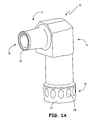
- FIG. 1A is a perspective view of an elbow fitting.
- FIG. 1B is a cross-sectional view of the fitting of FIG. 1A .
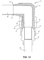
- FIG. 1C is a cross-sectional view of the fitting of FIG. 1A with a first tube and a second tube connected.
- FIG. 2 is a perspective view of a tee fitting.
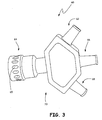
- FIG. 3 is a perspective view of a wye fitting.
- FIG. 1A is a perspective view of elbow fitting 10.
- FIG. 1B is a cross-sectional view of fitting 10 of FIG. 1A .
- FIG. 1C is a cross-sectional view of fitting 10 with a first tube and a second tube connected. While FIGS. 1A-1C show an elbow fitting, an elbow reducer could also be used.
- Elbow fitting 10 includes first tubular portion 12, second tubular portion 14 and transition portion 16.
- First tubular portion 12 includes first end 18 with lip 20 and includes a first taper.
- Second portion 14 includes second end 22 and a plurality of pockets 24 equally spaced circumferentially around second portion 14.
- Second portion 14 can have a second taper from transition portion 16 to second end 22.
- FIG. 1C further includes first tube 25, second tube 26, coupling member 30 and nut 32 with engagement mechanism 34 and thrust wire 36.
- Engagement mechanism 34 can be a spring loaded part or any other part that can engage pockets 24 to secure fitting 10 to coupling member 30.
- Fitting 10 can be made of stainless steel, nickel (including alloys), corrosion resistant steels (including ferrous based alloys), titanium (including alloys) or other metals depending on requirements. Fitting 10 can be made by machining, forging, casting or other methods depending on materials used and fitting specifications.
- first portion 12 includes a first taper of about four degrees and second portion 14 includes a second taper from transition portion 16 of about one degree.
- different tapers or no tapers may be used.
- Pockets 24 have a depth of about 0.040 inches (1.016 mm) to about 0.050 inches (1.27 mm) and are oval in shape.
- transition portion 16 is a ninety degree bend connecting first tubular portion 12 with second tubular portion 14. In alternative embodiments, transition portion 16 could be any bend in the range of forty five degrees to one hundred and thirty five degrees. Transition portion 16 can be formed separately from first portion 12 and second portion 14, and then joined together or transition portion 15 can be formed integral with first portion 12 and second portion 14.
- Pockets 24 are formed around outer circumference of second portion 14 so they are not affected by transition portion 16 shape or structure or by connection of a tube to first end 20. Pockets 24 can be located a distance from end 22 of second portion 14 to lessen stress levels in second end 22. Size, shape, amount and placement of pockets are dependent on system requirements and can vary. For example, pockets can be larger or smaller than pockets shown. Additionally, alternative embodiments of fitting 10 can include fewer or more pockets.
- First tube 25 connects to lip 20 of first end 18 of ferrule 10.
- First tube 25 can be welded into lip 20 of first end 18.
- first tube 25 can be brazed or inertia bonded to lip 20 of first end 18.
- Second tube 26 connects to coupling member 30. This can be a welded, brazed or bonded connection. Nut 32 fits around fitting 10.
- first tube 25 and second tube 26 are joined by fitting 10.
- coupling member 30 is connected to second end 22 of fitting 10.
- Nut 32 slides toward coupling member 30 to connect to fitting 10 and coupling member 30.
- Nut 32 connects to fitting 10 through engagement mechanism 34 engaging pockets 24 of fitting 10 and through thrust wire 36.
- Thrust wire 36 connects to fitting 10 on transition portion 16 of fitting 10 and works to ensure nut 32 does not slip over transition portion 16 of fitting 10.
- Nut 32 connects to coupling member 30 through threaded connection 40.
- first tube 25 When first tube 25 is connected to second tube 26 through coupling member 30 and fitting 10, nut 32 holds coupling member 30 and fitting 10 together through threads 40.
- Engagement mechanism 34 engages pockets 24 of fitting 10 to provide anti-rotation force to nut 32, ensuring that nut 32 stays securely connected through threads 40 and does not loosen or back off. This ensures that first tube 25 stays securely connected to second tube 26.
- fitting 10 securely joins tubes 25, 26 perpendicularly to each other, allowing fluid communication between the two tubes 25, 26 without requiring the lockwire which prior fittings often needed.
- prior art fittings such as ferrules, typically required lockwire to secure the nut and ensure that it did not loosen or back out.
- the lockwire was attached to the outside of the nut and to another object (coupling member, tube, etc.). This created a system that needed more space and left the lockwire exposed and in danger of breaking. A break in one or more of the braids of the lockwire could leave the tube in danger of disengaging.
- lockwire is costly, due to the need to braid the wires to add strength.
- the current system eliminates the need to use lockwire by placing a plurality of pockets 24 around the circumference of fitting 10 to be engaged by internal engagement mechanism 34 of nut 32. This internal engagement provides the anti-rotation force to ensure nut 32 does not loosen while eliminating the need for expensive and sometimes hazardous systems using lockwire.
- pockets 24 can have a gradual transition. This smooth, gradual transition reduces the amount of force required to pull engagement mechanism 34 from pockets 24, allowing for easier disassembly of tubes.
- FIG. 2 is a perspective view of tee (or "T") fitting 42 with first tubular portion 44, second tubular portion 46 (with pockets 48), third tubular portion 50 and transition portion 52.
- Tee fitting 42 is called a “tee fitting” due to transition portion 52 having a “T” shape, able to connect three tubes (not shown) to be in fluid communication with each other.
- First tubular portion 44 can include a first taper and can connect to a first tube by welding, brazing, bonding or other means.
- Second tubular portion 46 can connect to a second tube using a coupling member 30 and nut 32 with internal locking mechanism, as shown in FIG. 1C .
- Third tubular portion 50 can connect to a third tube using a variety of connection mechanisms, including a nut 32 with internal locking mechanism to engage outer pockets (similar to pockets 48) on an end of the third tube.
- FIG. 3 is a perspective view of wye (or "Y") fitting 60, due to transition portion 70 having a “Y” shape.
- Fitting 60 includes first tubular portion 62, second tubular portion 64 with pockets 65, third tubular portion 66, fourth tubular portion 68, and transition portion 70.
- First tubular portion 62, third tubular portion 66 and fourth tubular portion 68 can connect to tubes by welding, bonding, brazing or other means.
- Second tubular portion 64 can connect to a tube using a nut 32 with internal locking mechanism and a coupling device 30, as seen in FIG. 1C .
- Transition portion 70 of fitting 60 connects first, third and fourth tubular portions 62, 66, 68 with second tubular portion 64, to allow fluid communication between them. This allows for the connecting of a plurality of tubes or pipes (not shown).
- Fitting 60 is called a wye fitting because it can connect at least one tube (through a tubular portion, for example first tubular portion 62) with another tube (through another tubular portion, for example, second tubular portion 64) at an angle of up to forty five degrees. This allows for a smooth fluid flow between connecting tubes.
- fittings 10, 42 and 60 allow for the connection of a plurality of tubes or pipes by forming one end with circumferentially spaced outer pockets for use with a nut with an internal locking mechanism.
- the shape and design of transition portion 16, 52 and 70 can allow a variety of tubes to be connected together for a variety of different situations without the need for a lot of external locking mechanisms of past fittings.
- fittings 10, 42 and 60 can have a similar (if not identical) envelope to prior art fittings and ferrules, allowing for the replacement.
- This allows fittings 10, 42 and 60 to be able to accommodate current tubes (and coupling members) in use, needing to replace the fitting and nut in the system with fitting 10, 42, 60 or fittings of other shapes not specifically shown here and nut 32.
- Forming fittings 10, 42 and 60 with a plurality of pockets 24 for engagement also allows for fittings 10, 42 and 60 to be used with a variety of different nuts so long as the nut includes a means for engaging pockets 24.
- the devices could be reducers or other types of devices that connect a plurality of tubes using a nut with an internal locking mechanism which connects to circumferentially spaced pockets.
Landscapes
- Engineering & Computer Science (AREA)
- General Engineering & Computer Science (AREA)
- Mechanical Engineering (AREA)
- Mutual Connection Of Rods And Tubes (AREA)
- Quick-Acting Or Multi-Walled Pipe Joints (AREA)
- Joints With Pressure Members (AREA)
Abstract
Description
- The present invention relates to tube fittings.
- Fittings, couplings, reducers or ferrules, typically refer to objects used for fastening or joining other objects, such as two tubes. Fittings used for joining tubes are commonly made of metal and are engaged by a locking mechanism, such as a nut. When fittings join two tubes, one tube mechanically attaches to one end of the fitting and the other tube usually requires a coupling device to secure to the other end of the fitting. Fittings used in aerospace applications also typically require a locking feature to ensure the locking mechanism stays engaged to the fitting and does not unintentionally loosen (due to vibrations, wear or other causes). The locking mechanism can be lockwire. Lockwire is braided wire that can connect to the nut, securing the ferrule to a coupling and/or to another object to ensure that connections stay engaged. An alternative type of locking mechanism includes a nut engaging a coupling device.
- A fitting for use with a nut with an internal locking mechanism includes a first tubular portion with a first end and a first outer diameter for connecting to a first object; a second tubular portion with a second end and a second outer diameter for connecting to a second obj ect; a transition portion connecting the first tubular portion and the second tubular portion for fluid communication between the first tubular portion and the second tubular portion; and a plurality of pockets spaced circumferentially around the second tubular portion to engage the internal locking mechanism of the nut.
- A method of assembling a fitting for use with a nut with an internal locking mechanism and a fastener includes connecting a first tube to the fitting. The fitting includes a first tubular portion with a first end and a first outer diameter for connecting to a first object, a second tubular portion with a second end and a second outer diameter for connecting to a second object, a plurality of pockets spaced circumferentially around the second end portion to engage the internal locking mechanism of the nut, and a transition portion connecting the first portion to the second portion. The method further includes connecting a second tube to a coupling member with a fastener; connecting the coupling member to the second tubular portion of the fitting; and connecting the nut over the fitting and coupling member so that the internal locking mechanism of the nut engages the plurality of pockets of the fitting and the fastener of the nut engages the fastener of the coupling member to lock the fitting with the first tube to the coupling member with the second tube.
-
FIG. 1A is a perspective view of an elbow fitting. -
FIG. 1B is a cross-sectional view of the fitting ofFIG. 1A . -
FIG. 1C is a cross-sectional view of the fitting ofFIG. 1A with a first tube and a second tube connected. -
FIG. 2 is a perspective view of a tee fitting. -
FIG. 3 is a perspective view of a wye fitting. -
FIG. 1A is a perspective view ofelbow fitting 10.FIG. 1B is a cross-sectional view of fitting 10 ofFIG. 1A .FIG. 1C is a cross-sectional view of fitting 10 with a first tube and a second tube connected. WhileFIGS. 1A-1C show an elbow fitting, an elbow reducer could also be used. -
Elbow fitting 10 includes firsttubular portion 12, secondtubular portion 14 andtransition portion 16. Firsttubular portion 12 includesfirst end 18 withlip 20 and includes a first taper.Second portion 14 includessecond end 22 and a plurality ofpockets 24 equally spaced circumferentially aroundsecond portion 14.Second portion 14 can have a second taper fromtransition portion 16 tosecond end 22.FIG. 1C further includesfirst tube 25,second tube 26,coupling member 30 andnut 32 withengagement mechanism 34 andthrust wire 36.Engagement mechanism 34 can be a spring loaded part or any other part that can engagepockets 24 to secure fitting 10 to couplingmember 30. - Fitting 10 can be made of stainless steel, nickel (including alloys), corrosion resistant steels (including ferrous based alloys), titanium (including alloys) or other metals depending on requirements. Fitting 10 can be made by machining, forging, casting or other methods depending on materials used and fitting specifications.
- In the embodiment of
fitting 10 shown inFIGS. 1A-1C ,first portion 12 includes a first taper of about four degrees andsecond portion 14 includes a second taper fromtransition portion 16 of about one degree. In other embodiments, different tapers or no tapers may be used.Pockets 24 have a depth of about 0.040 inches (1.016 mm) to about 0.050 inches (1.27 mm) and are oval in shape. In the embodiment shown,transition portion 16 is a ninety degree bend connecting firsttubular portion 12 with secondtubular portion 14. In alternative embodiments,transition portion 16 could be any bend in the range of forty five degrees to one hundred and thirty five degrees.Transition portion 16 can be formed separately fromfirst portion 12 andsecond portion 14, and then joined together or transition portion 15 can be formed integral withfirst portion 12 andsecond portion 14. -
Pockets 24 are formed around outer circumference ofsecond portion 14 so they are not affected bytransition portion 16 shape or structure or by connection of a tube tofirst end 20.Pockets 24 can be located a distance fromend 22 ofsecond portion 14 to lessen stress levels insecond end 22. Size, shape, amount and placement of pockets are dependent on system requirements and can vary. For example, pockets can be larger or smaller than pockets shown. Additionally, alternative embodiments of fitting 10 can include fewer or more pockets. -
First tube 25 connects tolip 20 offirst end 18 offerrule 10.First tube 25 can be welded intolip 20 offirst end 18. Alternatively,first tube 25 can be brazed or inertia bonded to lip 20 offirst end 18.Second tube 26 connects tocoupling member 30. This can be a welded, brazed or bonded connection. Nut 32 fits aroundfitting 10. - As seen in
FIG. 1C ,first tube 25 andsecond tube 26 are joined by fitting 10. Specifically,coupling member 30 is connected tosecond end 22 of fitting 10.Nut 32 slides towardcoupling member 30 to connect to fitting 10 andcoupling member 30.Nut 32 connects to fitting 10 throughengagement mechanism 34engaging pockets 24 of fitting 10 and throughthrust wire 36.Thrust wire 36 connects to fitting 10 ontransition portion 16 of fitting 10 and works to ensurenut 32 does not slip overtransition portion 16 of fitting 10.Nut 32 connects to couplingmember 30 through threadedconnection 40. - When
first tube 25 is connected tosecond tube 26 throughcoupling member 30 and fitting 10,nut 32 holds couplingmember 30 and fitting 10 together throughthreads 40.Engagement mechanism 34 engagespockets 24 of fitting 10 to provide anti-rotation force tonut 32, ensuring thatnut 32 stays securely connected throughthreads 40 and does not loosen or back off. This ensures thatfirst tube 25 stays securely connected tosecond tube 26. - Through the use of fitting 10 with
first portion 12,second portion 14,transition portion 16 andpockets 24 for engagement withengagement mechanism 34 ofnut 32, fitting 10 securely joinstubes tubes pockets 24 around the circumference of fitting 10 to be engaged byinternal engagement mechanism 34 ofnut 32. This internal engagement provides the anti-rotation force to ensurenut 32 does not loosen while eliminating the need for expensive and sometimes hazardous systems using lockwire. - To allow for a smooth retraction of
nut 32 from fitting 10, pockets 24 can have a gradual transition. This smooth, gradual transition reduces the amount of force required to pullengagement mechanism 34 frompockets 24, allowing for easier disassembly of tubes. -
FIG. 2 is a perspective view of tee (or "T") fitting 42 with firsttubular portion 44, second tubular portion 46 (with pockets 48), thirdtubular portion 50 andtransition portion 52. Tee fitting 42 is called a "tee fitting" due totransition portion 52 having a "T" shape, able to connect three tubes (not shown) to be in fluid communication with each other. - First
tubular portion 44 can include a first taper and can connect to a first tube by welding, brazing, bonding or other means. Secondtubular portion 46 can connect to a second tube using acoupling member 30 andnut 32 with internal locking mechanism, as shown inFIG. 1C . Thirdtubular portion 50 can connect to a third tube using a variety of connection mechanisms, including anut 32 with internal locking mechanism to engage outer pockets (similar to pockets 48) on an end of the third tube. -
FIG. 3 is a perspective view of wye (or "Y") fitting 60, due totransition portion 70 having a "Y" shape. Fitting 60 includes firsttubular portion 62, secondtubular portion 64 withpockets 65, thirdtubular portion 66, fourthtubular portion 68, andtransition portion 70. - First
tubular portion 62, thirdtubular portion 66 and fourthtubular portion 68 can connect to tubes by welding, bonding, brazing or other means. Secondtubular portion 64 can connect to a tube using anut 32 with internal locking mechanism and acoupling device 30, as seen inFIG. 1C . -
Transition portion 70 of fitting 60 connects first, third and fourthtubular portions tubular portion 64, to allow fluid communication between them. This allows for the connecting of a plurality of tubes or pipes (not shown). Fitting 60 is called a wye fitting because it can connect at least one tube (through a tubular portion, for example first tubular portion 62) with another tube (through another tubular portion, for example, second tubular portion 64) at an angle of up to forty five degrees. This allows for a smooth fluid flow between connecting tubes. - In summary, all of
fittings transition portion - Additionally, by forming
engagement mechanism 34 internally to the fitting,fittings fittings nut 32. Formingfittings pockets 24 for engagement also allows forfittings pockets 24. - While the invention has been described in reference to using a nut with an internal locking mechanism with
fittings - While the term "fitting" is used to refer to the devices in
FIGS. 1A-3 , the devices could be reducers or other types of devices that connect a plurality of tubes using a nut with an internal locking mechanism which connects to circumferentially spaced pockets. - While the invention has been described with reference to an exemplary embodiment(s), it will be understood by those skilled in the art that various changes may be made and equivalents may be substituted for elements thereof without departing from the scope of the invention. In addition, many modifications may be made to adapt a particular situation or material to the teachings of the invention without departing from the essential scope thereof. Therefore, it is intended that the invention not be limited to the particular embodiment(s) disclosed, but that the invention will include all embodiments falling within the scope of the appended claims.
Claims (15)
- A fitting for use with a nut with an internal locking mechanism, the fitting comprising:a first tubular portion with a first end and a first outer diameter for connecting to a first object;a second tubular portion with a second end and a second outer diameter for connecting to a second object;a transition portion connecting the first tubular portion and the second tubular portion for fluid communication between the first tubular portion and the second tubular portion; anda plurality of pockets spaced circumferentially around the second tubular portion to engage the internal locking mechanism of the nut.
- The fitting of claim 1, wherein the fitting is an elbow fitting.
- The fitting of claim 2, wherein the transition portion comprises a forty-five degree bend or a ninety degree bend between the first tubular portion and the second tubular portion.
- The fitting of claim 1, wherein the fitting is a tee fitting.
- The fitting of claim 4, wherein the tee fitting transition portion includes a ninety degree bend between the first tubular portion and the second tubular portion.
- The fitting of claim 1, wherein the fitting is a wye fitting.
- The fitting of claim 6, and further comprising:a third tubular portion with a third end and a third outer diameter for connecting to a third object.
- The fitting of claim 7, wherein the first tubular portion and the third tubular portion connect to the second tubular portion at up to 45 degree angles.
- The fitting of claim 7 or 8, and further comprising:at least one additional tubular portion connecting to the transition portion to allow fluid communication between the second tubular portion and the first, third and at least one additional tubular portions.
- A fitting as claimed in any preceding claim for joining a plurality of tubes, the fitting comprising:a nut with an internal locking mechanism;said first tubular portion with a first end for connecting to a first tube; andsaid second tubular portion with a second end for connecting to a second tube.
- The fitting of any preceding claim, wherein the first tubular portion is tapered.
- A method of assembling a fitting for use with a nut with an internal locking mechanism and a fastener, the method comprising:connecting a first tube to the fitting, the fitting comprising:a first tubular portion with a first end and a first outer diameter for connecting to a first object,a second tubular portion with a second end and a second outer diameter for connecting to a second object,a plurality of pockets spaced circumferentially around the second end portion to engage the internal locking mechanism of the nut, anda transition portion connecting the first portion to the second portion;connecting a second tube to a coupling member with a fastener;connecting the coupling member to the second tubular portion of the fitting; andconnecting the nut over the fitting and coupling member so that the internal locking mechanism of the nut engages the plurality of pockets of the fitting and the fastener of the nut engages the fastener of the coupling member to lock the fitting with the first tube to the coupling member with the second tube.
- The method of claim 12, and further comprising:connecting one or more additional tubes to one or more additional tubular portions of the fitting, wherein the one or more additional tubular portions of the fitting are in fluid communication with the first and second tubular portions.
- The method of claim 12 or 13, wherein the first tube is connected to the fitting by welding, brazing or bonding.
- The method of claim 12, 13 or 14, wherein the fitting is a wye fitting, a tee fitting or an elbow fitting.
Applications Claiming Priority (2)
| Application Number | Priority Date | Filing Date | Title |
|---|---|---|---|
| US13/323,972 US8523240B2 (en) | 2011-12-13 | 2011-12-13 | Ferrule |
| US13/711,148 US20130145607A1 (en) | 2011-12-13 | 2012-12-11 | Fitting for use with nut with internal locking mechanism |
Publications (3)
| Publication Number | Publication Date |
|---|---|
| EP2604901A2 true EP2604901A2 (en) | 2013-06-19 |
| EP2604901A3 EP2604901A3 (en) | 2016-07-27 |
| EP2604901B1 EP2604901B1 (en) | 2018-10-17 |
Family
ID=47504689
Family Applications (1)
| Application Number | Title | Priority Date | Filing Date |
|---|---|---|---|
| EP12197094.1A Active EP2604901B1 (en) | 2011-12-13 | 2012-12-13 | Fitting for use with nut with internal locking mechanism |
Country Status (2)
| Country | Link |
|---|---|
| US (1) | US20130145607A1 (en) |
| EP (1) | EP2604901B1 (en) |
Cited By (1)
| Publication number | Priority date | Publication date | Assignee | Title |
|---|---|---|---|---|
| ITUB20159356A1 (en) * | 2015-12-28 | 2017-06-28 | Pipes & Fittings Eqofluids Sl | HYDRAULIC WALL SYSTEM WITH ANTI-ROTATION WALL OF THE HYDRAULIC COMPONENT |
Families Citing this family (2)
| Publication number | Priority date | Publication date | Assignee | Title |
|---|---|---|---|---|
| US9080594B2 (en) | 2012-09-28 | 2015-07-14 | United Technologies Corporation | Removable self-locking plug |
| US10234064B2 (en) * | 2016-10-06 | 2019-03-19 | Sps Technologies, Llc | Variable friction coupling assembly |
Family Cites Families (11)
| Publication number | Priority date | Publication date | Assignee | Title |
|---|---|---|---|---|
| US463281A (en) * | 1891-11-17 | Sewer-pipe | ||
| US3486771A (en) * | 1968-09-30 | 1969-12-30 | Tech Aero Inc | Connector fitting |
| US4792160A (en) * | 1987-12-07 | 1988-12-20 | Hwang Biing Yih | Structure for pipe fittings |
| US5110157A (en) * | 1990-11-19 | 1992-05-05 | Chen Kun Yang | Structure of a water faucet joint |
| US6857665B2 (en) * | 2002-07-24 | 2005-02-22 | Parker-Hannifin Corporation | Lockwireless anti-rotation fitting |
| US7600789B2 (en) * | 2002-07-24 | 2009-10-13 | Vyse Gerrard N | Lockwireless anti-rotation fitting |
| KR100543135B1 (en) * | 2003-11-15 | 2006-01-20 | 주식회사 화승알앤에이 | Hose Clamping Structure |
| US7156425B2 (en) * | 2003-11-19 | 2007-01-02 | Manuel Diaz Atkinson | Quick connect and quick disconnect plumbing apparatus |
| WO2006031386A2 (en) * | 2004-09-10 | 2006-03-23 | Sps Technologies, Llc | Fluid coupling assembly with integral retention mechanism |
| US20070164566A1 (en) * | 2006-01-19 | 2007-07-19 | Nilesh Patel | Lockwireless coupling assembly |
| US8641099B2 (en) * | 2012-07-05 | 2014-02-04 | United Technologies Corporation | Coupling with one-piece plural nipples |
-
2012
- 2012-12-11 US US13/711,148 patent/US20130145607A1/en not_active Abandoned
- 2012-12-13 EP EP12197094.1A patent/EP2604901B1/en active Active
Non-Patent Citations (1)
| Title |
|---|
| None |
Cited By (1)
| Publication number | Priority date | Publication date | Assignee | Title |
|---|---|---|---|---|
| ITUB20159356A1 (en) * | 2015-12-28 | 2017-06-28 | Pipes & Fittings Eqofluids Sl | HYDRAULIC WALL SYSTEM WITH ANTI-ROTATION WALL OF THE HYDRAULIC COMPONENT |
Also Published As
| Publication number | Publication date |
|---|---|
| EP2604901A3 (en) | 2016-07-27 |
| US20130145607A1 (en) | 2013-06-13 |
| EP2604901B1 (en) | 2018-10-17 |
Similar Documents
| Publication | Publication Date | Title |
|---|---|---|
| EP2604900B1 (en) | Ferrule | |
| US7500699B2 (en) | Clamping mechanical pipe coupling derived from a standard fitting | |
| AU2016244061B2 (en) | Swage fitting | |
| JP2008513687A (en) | Mechanical pipe fittings derived from standard fittings | |
| US20150130183A1 (en) | Double wall tube adapter and joint | |
| CN109424807B (en) | Tongue-and-groove joint | |
| WO2008008172A2 (en) | Triple-expanded mechanical pipe coupling derived from a standard fitting | |
| KR101495659B1 (en) | Coupling and joint for fixedly and sealingly securing components to one another | |
| EP2604901B1 (en) | Fitting for use with nut with internal locking mechanism | |
| KR102173565B1 (en) | Side lock conduit and joint assembly | |
| EP3389919B1 (en) | Method for connection and tubular connection assembly for improved fatigue performance of metallic risers | |
| JP2017538073A (en) | Pipe coupling device | |
| US9121530B2 (en) | Tube fitting assembly | |
| JP2010096305A (en) | Pipe coupling structure | |
| EP4198365A1 (en) | Dynamic bellows fluid fitting | |
| US9951895B2 (en) | Two-piece self-locking mechanism for tube assemblies | |
| JP7292314B2 (en) | Tubular elements and tubular assemblies | |
| RU42857U1 (en) | DEVICE FOR SEALING PIPE CONNECTIONS | |
| CN111051758A (en) | Formed pipe end sections and pipe thread connections for pipes | |
| JP6380905B1 (en) | Water piping connection structure | |
| WO2014042912A1 (en) | Fluid coupling |
Legal Events
| Date | Code | Title | Description |
|---|---|---|---|
| PUAI | Public reference made under article 153(3) epc to a published international application that has entered the european phase |
Free format text: ORIGINAL CODE: 0009012 |
|
| AK | Designated contracting states |
Kind code of ref document: A2 Designated state(s): AL AT BE BG CH CY CZ DE DK EE ES FI FR GB GR HR HU IE IS IT LI LT LU LV MC MK MT NL NO PL PT RO RS SE SI SK SM TR |
|
| AX | Request for extension of the european patent |
Extension state: BA ME |
|
| PUAL | Search report despatched |
Free format text: ORIGINAL CODE: 0009013 |
|
| AK | Designated contracting states |
Kind code of ref document: A3 Designated state(s): AL AT BE BG CH CY CZ DE DK EE ES FI FR GB GR HR HU IE IS IT LI LT LU LV MC MK MT NL NO PL PT RO RS SE SI SK SM TR |
|
| AX | Request for extension of the european patent |
Extension state: BA ME |
|
| RIC1 | Information provided on ipc code assigned before grant |
Ipc: F16L 41/02 20060101ALN20160622BHEP Ipc: F16L 43/00 20060101ALN20160622BHEP Ipc: F16L 19/00 20060101AFI20160622BHEP Ipc: F16L 41/03 20060101ALN20160622BHEP |
|
| RAP1 | Party data changed (applicant data changed or rights of an application transferred) |
Owner name: UNITED TECHNOLOGIES CORPORATION |
|
| STAA | Information on the status of an ep patent application or granted ep patent |
Free format text: STATUS: REQUEST FOR EXAMINATION WAS MADE |
|
| 17P | Request for examination filed |
Effective date: 20170127 |
|
| RBV | Designated contracting states (corrected) |
Designated state(s): AL AT BE BG CH CY CZ DE DK EE ES FI FR GB GR HR HU IE IS IT LI LT LU LV MC MK MT NL NO PL PT RO RS SE SI SK SM TR |
|
| STAA | Information on the status of an ep patent application or granted ep patent |
Free format text: STATUS: EXAMINATION IS IN PROGRESS |
|
| 17Q | First examination report despatched |
Effective date: 20171031 |
|
| REG | Reference to a national code |
Ref country code: DE Ref legal event code: R079 Ref document number: 602012052262 Country of ref document: DE Free format text: PREVIOUS MAIN CLASS: F16L0037230000 Ipc: F16L0019000000 |
|
| GRAP | Despatch of communication of intention to grant a patent |
Free format text: ORIGINAL CODE: EPIDOSNIGR1 |
|
| STAA | Information on the status of an ep patent application or granted ep patent |
Free format text: STATUS: GRANT OF PATENT IS INTENDED |
|
| RIC1 | Information provided on ipc code assigned before grant |
Ipc: F16L 43/00 20060101ALN20180424BHEP Ipc: F16L 41/03 20060101ALN20180424BHEP Ipc: F16L 41/02 20060101ALN20180424BHEP Ipc: F16L 19/00 20060101AFI20180424BHEP |
|
| INTG | Intention to grant announced |
Effective date: 20180517 |
|
| GRAS | Grant fee paid |
Free format text: ORIGINAL CODE: EPIDOSNIGR3 |
|
| GRAA | (expected) grant |
Free format text: ORIGINAL CODE: 0009210 |
|
| STAA | Information on the status of an ep patent application or granted ep patent |
Free format text: STATUS: THE PATENT HAS BEEN GRANTED |
|
| AK | Designated contracting states |
Kind code of ref document: B1 Designated state(s): AL AT BE BG CH CY CZ DE DK EE ES FI FR GB GR HR HU IE IS IT LI LT LU LV MC MK MT NL NO PL PT RO RS SE SI SK SM TR |
|
| REG | Reference to a national code |
Ref country code: GB Ref legal event code: FG4D |
|
| REG | Reference to a national code |
Ref country code: CH Ref legal event code: EP |
|
| REG | Reference to a national code |
Ref country code: IE Ref legal event code: FG4D |
|
| REG | Reference to a national code |
Ref country code: DE Ref legal event code: R096 Ref document number: 602012052262 Country of ref document: DE Ref country code: AT Ref legal event code: REF Ref document number: 1054458 Country of ref document: AT Kind code of ref document: T Effective date: 20181115 |
|
| REG | Reference to a national code |
Ref country code: NL Ref legal event code: MP Effective date: 20181017 |
|
| REG | Reference to a national code |
Ref country code: LT Ref legal event code: MG4D |
|
| REG | Reference to a national code |
Ref country code: AT Ref legal event code: MK05 Ref document number: 1054458 Country of ref document: AT Kind code of ref document: T Effective date: 20181017 |
|
| PG25 | Lapsed in a contracting state [announced via postgrant information from national office to epo] |
Ref country code: NL Free format text: LAPSE BECAUSE OF FAILURE TO SUBMIT A TRANSLATION OF THE DESCRIPTION OR TO PAY THE FEE WITHIN THE PRESCRIBED TIME-LIMIT Effective date: 20181017 |
|
| PG25 | Lapsed in a contracting state [announced via postgrant information from national office to epo] |
Ref country code: AT Free format text: LAPSE BECAUSE OF FAILURE TO SUBMIT A TRANSLATION OF THE DESCRIPTION OR TO PAY THE FEE WITHIN THE PRESCRIBED TIME-LIMIT Effective date: 20181017 Ref country code: HR Free format text: LAPSE BECAUSE OF FAILURE TO SUBMIT A TRANSLATION OF THE DESCRIPTION OR TO PAY THE FEE WITHIN THE PRESCRIBED TIME-LIMIT Effective date: 20181017 Ref country code: LT Free format text: LAPSE BECAUSE OF FAILURE TO SUBMIT A TRANSLATION OF THE DESCRIPTION OR TO PAY THE FEE WITHIN THE PRESCRIBED TIME-LIMIT Effective date: 20181017 Ref country code: PL Free format text: LAPSE BECAUSE OF FAILURE TO SUBMIT A TRANSLATION OF THE DESCRIPTION OR TO PAY THE FEE WITHIN THE PRESCRIBED TIME-LIMIT Effective date: 20181017 Ref country code: BG Free format text: LAPSE BECAUSE OF FAILURE TO SUBMIT A TRANSLATION OF THE DESCRIPTION OR TO PAY THE FEE WITHIN THE PRESCRIBED TIME-LIMIT Effective date: 20190117 Ref country code: ES Free format text: LAPSE BECAUSE OF FAILURE TO SUBMIT A TRANSLATION OF THE DESCRIPTION OR TO PAY THE FEE WITHIN THE PRESCRIBED TIME-LIMIT Effective date: 20181017 Ref country code: IS Free format text: LAPSE BECAUSE OF FAILURE TO SUBMIT A TRANSLATION OF THE DESCRIPTION OR TO PAY THE FEE WITHIN THE PRESCRIBED TIME-LIMIT Effective date: 20190217 Ref country code: NO Free format text: LAPSE BECAUSE OF FAILURE TO SUBMIT A TRANSLATION OF THE DESCRIPTION OR TO PAY THE FEE WITHIN THE PRESCRIBED TIME-LIMIT Effective date: 20190117 Ref country code: FI Free format text: LAPSE BECAUSE OF FAILURE TO SUBMIT A TRANSLATION OF THE DESCRIPTION OR TO PAY THE FEE WITHIN THE PRESCRIBED TIME-LIMIT Effective date: 20181017 Ref country code: LV Free format text: LAPSE BECAUSE OF FAILURE TO SUBMIT A TRANSLATION OF THE DESCRIPTION OR TO PAY THE FEE WITHIN THE PRESCRIBED TIME-LIMIT Effective date: 20181017 |
|
| PG25 | Lapsed in a contracting state [announced via postgrant information from national office to epo] |
Ref country code: RS Free format text: LAPSE BECAUSE OF FAILURE TO SUBMIT A TRANSLATION OF THE DESCRIPTION OR TO PAY THE FEE WITHIN THE PRESCRIBED TIME-LIMIT Effective date: 20181017 Ref country code: SE Free format text: LAPSE BECAUSE OF FAILURE TO SUBMIT A TRANSLATION OF THE DESCRIPTION OR TO PAY THE FEE WITHIN THE PRESCRIBED TIME-LIMIT Effective date: 20181017 Ref country code: AL Free format text: LAPSE BECAUSE OF FAILURE TO SUBMIT A TRANSLATION OF THE DESCRIPTION OR TO PAY THE FEE WITHIN THE PRESCRIBED TIME-LIMIT Effective date: 20181017 Ref country code: GR Free format text: LAPSE BECAUSE OF FAILURE TO SUBMIT A TRANSLATION OF THE DESCRIPTION OR TO PAY THE FEE WITHIN THE PRESCRIBED TIME-LIMIT Effective date: 20190118 Ref country code: PT Free format text: LAPSE BECAUSE OF FAILURE TO SUBMIT A TRANSLATION OF THE DESCRIPTION OR TO PAY THE FEE WITHIN THE PRESCRIBED TIME-LIMIT Effective date: 20190217 |
|
| REG | Reference to a national code |
Ref country code: DE Ref legal event code: R097 Ref document number: 602012052262 Country of ref document: DE |
|
| PG25 | Lapsed in a contracting state [announced via postgrant information from national office to epo] |
Ref country code: DK Free format text: LAPSE BECAUSE OF FAILURE TO SUBMIT A TRANSLATION OF THE DESCRIPTION OR TO PAY THE FEE WITHIN THE PRESCRIBED TIME-LIMIT Effective date: 20181017 Ref country code: CZ Free format text: LAPSE BECAUSE OF FAILURE TO SUBMIT A TRANSLATION OF THE DESCRIPTION OR TO PAY THE FEE WITHIN THE PRESCRIBED TIME-LIMIT Effective date: 20181017 Ref country code: IT Free format text: LAPSE BECAUSE OF FAILURE TO SUBMIT A TRANSLATION OF THE DESCRIPTION OR TO PAY THE FEE WITHIN THE PRESCRIBED TIME-LIMIT Effective date: 20181017 |
|
| REG | Reference to a national code |
Ref country code: CH Ref legal event code: PL |
|
| PLBE | No opposition filed within time limit |
Free format text: ORIGINAL CODE: 0009261 |
|
| STAA | Information on the status of an ep patent application or granted ep patent |
Free format text: STATUS: NO OPPOSITION FILED WITHIN TIME LIMIT |
|
| PG25 | Lapsed in a contracting state [announced via postgrant information from national office to epo] |
Ref country code: LU Free format text: LAPSE BECAUSE OF NON-PAYMENT OF DUE FEES Effective date: 20181213 Ref country code: RO Free format text: LAPSE BECAUSE OF FAILURE TO SUBMIT A TRANSLATION OF THE DESCRIPTION OR TO PAY THE FEE WITHIN THE PRESCRIBED TIME-LIMIT Effective date: 20181017 Ref country code: EE Free format text: LAPSE BECAUSE OF FAILURE TO SUBMIT A TRANSLATION OF THE DESCRIPTION OR TO PAY THE FEE WITHIN THE PRESCRIBED TIME-LIMIT Effective date: 20181017 Ref country code: SM Free format text: LAPSE BECAUSE OF FAILURE TO SUBMIT A TRANSLATION OF THE DESCRIPTION OR TO PAY THE FEE WITHIN THE PRESCRIBED TIME-LIMIT Effective date: 20181017 Ref country code: SK Free format text: LAPSE BECAUSE OF FAILURE TO SUBMIT A TRANSLATION OF THE DESCRIPTION OR TO PAY THE FEE WITHIN THE PRESCRIBED TIME-LIMIT Effective date: 20181017 Ref country code: MC Free format text: LAPSE BECAUSE OF FAILURE TO SUBMIT A TRANSLATION OF THE DESCRIPTION OR TO PAY THE FEE WITHIN THE PRESCRIBED TIME-LIMIT Effective date: 20181017 |
|
| REG | Reference to a national code |
Ref country code: IE Ref legal event code: MM4A |
|
| 26N | No opposition filed |
Effective date: 20190718 |
|
| REG | Reference to a national code |
Ref country code: BE Ref legal event code: MM Effective date: 20181231 |
|
| PG25 | Lapsed in a contracting state [announced via postgrant information from national office to epo] |
Ref country code: IE Free format text: LAPSE BECAUSE OF NON-PAYMENT OF DUE FEES Effective date: 20181213 Ref country code: SI Free format text: LAPSE BECAUSE OF FAILURE TO SUBMIT A TRANSLATION OF THE DESCRIPTION OR TO PAY THE FEE WITHIN THE PRESCRIBED TIME-LIMIT Effective date: 20181017 |
|
| PG25 | Lapsed in a contracting state [announced via postgrant information from national office to epo] |
Ref country code: BE Free format text: LAPSE BECAUSE OF NON-PAYMENT OF DUE FEES Effective date: 20181231 |
|
| PG25 | Lapsed in a contracting state [announced via postgrant information from national office to epo] |
Ref country code: LI Free format text: LAPSE BECAUSE OF NON-PAYMENT OF DUE FEES Effective date: 20181231 Ref country code: CH Free format text: LAPSE BECAUSE OF NON-PAYMENT OF DUE FEES Effective date: 20181231 |
|
| PG25 | Lapsed in a contracting state [announced via postgrant information from national office to epo] |
Ref country code: MT Free format text: LAPSE BECAUSE OF NON-PAYMENT OF DUE FEES Effective date: 20181213 |
|
| PG25 | Lapsed in a contracting state [announced via postgrant information from national office to epo] |
Ref country code: TR Free format text: LAPSE BECAUSE OF FAILURE TO SUBMIT A TRANSLATION OF THE DESCRIPTION OR TO PAY THE FEE WITHIN THE PRESCRIBED TIME-LIMIT Effective date: 20181017 |
|
| PG25 | Lapsed in a contracting state [announced via postgrant information from national office to epo] |
Ref country code: MK Free format text: LAPSE BECAUSE OF NON-PAYMENT OF DUE FEES Effective date: 20181017 Ref country code: HU Free format text: LAPSE BECAUSE OF FAILURE TO SUBMIT A TRANSLATION OF THE DESCRIPTION OR TO PAY THE FEE WITHIN THE PRESCRIBED TIME-LIMIT; INVALID AB INITIO Effective date: 20121213 Ref country code: CY Free format text: LAPSE BECAUSE OF FAILURE TO SUBMIT A TRANSLATION OF THE DESCRIPTION OR TO PAY THE FEE WITHIN THE PRESCRIBED TIME-LIMIT Effective date: 20181017 |
|
| REG | Reference to a national code |
Ref country code: DE Ref legal event code: R081 Ref document number: 602012052262 Country of ref document: DE Owner name: RAYTHEON TECHNOLOGIES CORPORATION (N.D.GES.D.S, US Free format text: FORMER OWNER: UNITED TECHNOLOGIES CORPORATION, FARMINGTON, CONN., US Ref country code: DE Ref legal event code: R081 Ref document number: 602012052262 Country of ref document: DE Owner name: RTX CORPORATION (N.D.GES.D. STAATES DELAWARE),, US Free format text: FORMER OWNER: UNITED TECHNOLOGIES CORPORATION, FARMINGTON, CONN., US |
|
| P01 | Opt-out of the competence of the unified patent court (upc) registered |
Effective date: 20230520 |
|
| REG | Reference to a national code |
Ref country code: DE Ref legal event code: R081 Ref document number: 602012052262 Country of ref document: DE Owner name: RTX CORPORATION (N.D.GES.D. STAATES DELAWARE),, US Free format text: FORMER OWNER: RAYTHEON TECHNOLOGIES CORPORATION (N.D.GES.D.STAATES DELAWARE), ARLINGTON, VA, US |
|
| PGFP | Annual fee paid to national office [announced via postgrant information from national office to epo] |
Ref country code: DE Payment date: 20251126 Year of fee payment: 14 |
|
| PGFP | Annual fee paid to national office [announced via postgrant information from national office to epo] |
Ref country code: GB Payment date: 20251120 Year of fee payment: 14 |
|
| PGFP | Annual fee paid to national office [announced via postgrant information from national office to epo] |
Ref country code: FR Payment date: 20251119 Year of fee payment: 14 |