EP2604825A2 - Controller for cooling the turbine section of a gas turbine engine - Google Patents
Controller for cooling the turbine section of a gas turbine engine Download PDFInfo
- Publication number
- EP2604825A2 EP2604825A2 EP12193315.4A EP12193315A EP2604825A2 EP 2604825 A2 EP2604825 A2 EP 2604825A2 EP 12193315 A EP12193315 A EP 12193315A EP 2604825 A2 EP2604825 A2 EP 2604825A2
- Authority
- EP
- European Patent Office
- Prior art keywords
- cooled
- cooling air
- gas turbine
- temperature
- temperatures
- Prior art date
- Legal status (The legal status is an assumption and is not a legal conclusion. Google has not performed a legal analysis and makes no representation as to the accuracy of the status listed.)
- Granted
Links
Images


Classifications
-
- F—MECHANICAL ENGINEERING; LIGHTING; HEATING; WEAPONS; BLASTING
- F02—COMBUSTION ENGINES; HOT-GAS OR COMBUSTION-PRODUCT ENGINE PLANTS
- F02C—GAS-TURBINE PLANTS; AIR INTAKES FOR JET-PROPULSION PLANTS; CONTROLLING FUEL SUPPLY IN AIR-BREATHING JET-PROPULSION PLANTS
- F02C7/00—Features, components parts, details or accessories, not provided for in, or of interest apart form groups F02C1/00 - F02C6/00; Air intakes for jet-propulsion plants
- F02C7/12—Cooling of plants
- F02C7/16—Cooling of plants characterised by cooling medium
- F02C7/18—Cooling of plants characterised by cooling medium the medium being gaseous, e.g. air
- F02C7/185—Cooling means for reducing the temperature of the cooling air or gas
-
- F—MECHANICAL ENGINEERING; LIGHTING; HEATING; WEAPONS; BLASTING
- F01—MACHINES OR ENGINES IN GENERAL; ENGINE PLANTS IN GENERAL; STEAM ENGINES
- F01D—NON-POSITIVE DISPLACEMENT MACHINES OR ENGINES, e.g. STEAM TURBINES
- F01D11/00—Preventing or minimising internal leakage of working-fluid, e.g. between stages
- F01D11/08—Preventing or minimising internal leakage of working-fluid, e.g. between stages for sealing space between rotor blade tips and stator
- F01D11/14—Adjusting or regulating tip-clearance, i.e. distance between rotor-blade tips and stator casing
- F01D11/20—Actively adjusting tip-clearance
- F01D11/24—Actively adjusting tip-clearance by selectively cooling-heating stator or rotor components
-
- F—MECHANICAL ENGINEERING; LIGHTING; HEATING; WEAPONS; BLASTING
- F01—MACHINES OR ENGINES IN GENERAL; ENGINE PLANTS IN GENERAL; STEAM ENGINES
- F01D—NON-POSITIVE DISPLACEMENT MACHINES OR ENGINES, e.g. STEAM TURBINES
- F01D17/00—Regulating or controlling by varying flow
- F01D17/02—Arrangement of sensing elements
-
- F—MECHANICAL ENGINEERING; LIGHTING; HEATING; WEAPONS; BLASTING
- F01—MACHINES OR ENGINES IN GENERAL; ENGINE PLANTS IN GENERAL; STEAM ENGINES
- F01D—NON-POSITIVE DISPLACEMENT MACHINES OR ENGINES, e.g. STEAM TURBINES
- F01D17/00—Regulating or controlling by varying flow
- F01D17/02—Arrangement of sensing elements
- F01D17/08—Arrangement of sensing elements responsive to condition of working-fluid, e.g. pressure
- F01D17/085—Arrangement of sensing elements responsive to condition of working-fluid, e.g. pressure to temperature
-
- F—MECHANICAL ENGINEERING; LIGHTING; HEATING; WEAPONS; BLASTING
- F01—MACHINES OR ENGINES IN GENERAL; ENGINE PLANTS IN GENERAL; STEAM ENGINES
- F01D—NON-POSITIVE DISPLACEMENT MACHINES OR ENGINES, e.g. STEAM TURBINES
- F01D5/00—Blades; Blade-carrying members; Heating, heat-insulating, cooling or antivibration means on the blades or the members
- F01D5/02—Blade-carrying members, e.g. rotors
- F01D5/08—Heating, heat-insulating or cooling means
-
- F—MECHANICAL ENGINEERING; LIGHTING; HEATING; WEAPONS; BLASTING
- F01—MACHINES OR ENGINES IN GENERAL; ENGINE PLANTS IN GENERAL; STEAM ENGINES
- F01D—NON-POSITIVE DISPLACEMENT MACHINES OR ENGINES, e.g. STEAM TURBINES
- F01D5/00—Blades; Blade-carrying members; Heating, heat-insulating, cooling or antivibration means on the blades or the members
- F01D5/02—Blade-carrying members, e.g. rotors
- F01D5/08—Heating, heat-insulating or cooling means
- F01D5/081—Cooling fluid being directed on the side of the rotor disc or at the roots of the blades
-
- F—MECHANICAL ENGINEERING; LIGHTING; HEATING; WEAPONS; BLASTING
- F01—MACHINES OR ENGINES IN GENERAL; ENGINE PLANTS IN GENERAL; STEAM ENGINES
- F01D—NON-POSITIVE DISPLACEMENT MACHINES OR ENGINES, e.g. STEAM TURBINES
- F01D5/00—Blades; Blade-carrying members; Heating, heat-insulating, cooling or antivibration means on the blades or the members
- F01D5/02—Blade-carrying members, e.g. rotors
- F01D5/08—Heating, heat-insulating or cooling means
- F01D5/081—Cooling fluid being directed on the side of the rotor disc or at the roots of the blades
- F01D5/082—Cooling fluid being directed on the side of the rotor disc or at the roots of the blades on the side of the rotor disc
-
- F—MECHANICAL ENGINEERING; LIGHTING; HEATING; WEAPONS; BLASTING
- F01—MACHINES OR ENGINES IN GENERAL; ENGINE PLANTS IN GENERAL; STEAM ENGINES
- F01D—NON-POSITIVE DISPLACEMENT MACHINES OR ENGINES, e.g. STEAM TURBINES
- F01D5/00—Blades; Blade-carrying members; Heating, heat-insulating, cooling or antivibration means on the blades or the members
- F01D5/02—Blade-carrying members, e.g. rotors
- F01D5/08—Heating, heat-insulating or cooling means
- F01D5/085—Heating, heat-insulating or cooling means cooling fluid circulating inside the rotor
-
- F—MECHANICAL ENGINEERING; LIGHTING; HEATING; WEAPONS; BLASTING
- F01—MACHINES OR ENGINES IN GENERAL; ENGINE PLANTS IN GENERAL; STEAM ENGINES
- F01D—NON-POSITIVE DISPLACEMENT MACHINES OR ENGINES, e.g. STEAM TURBINES
- F01D5/00—Blades; Blade-carrying members; Heating, heat-insulating, cooling or antivibration means on the blades or the members
- F01D5/02—Blade-carrying members, e.g. rotors
- F01D5/08—Heating, heat-insulating or cooling means
- F01D5/085—Heating, heat-insulating or cooling means cooling fluid circulating inside the rotor
- F01D5/087—Heating, heat-insulating or cooling means cooling fluid circulating inside the rotor in the radial passages of the rotor disc
-
- F—MECHANICAL ENGINEERING; LIGHTING; HEATING; WEAPONS; BLASTING
- F01—MACHINES OR ENGINES IN GENERAL; ENGINE PLANTS IN GENERAL; STEAM ENGINES
- F01D—NON-POSITIVE DISPLACEMENT MACHINES OR ENGINES, e.g. STEAM TURBINES
- F01D5/00—Blades; Blade-carrying members; Heating, heat-insulating, cooling or antivibration means on the blades or the members
- F01D5/02—Blade-carrying members, e.g. rotors
- F01D5/08—Heating, heat-insulating or cooling means
- F01D5/085—Heating, heat-insulating or cooling means cooling fluid circulating inside the rotor
- F01D5/088—Heating, heat-insulating or cooling means cooling fluid circulating inside the rotor in a closed cavity
-
- F—MECHANICAL ENGINEERING; LIGHTING; HEATING; WEAPONS; BLASTING
- F02—COMBUSTION ENGINES; HOT-GAS OR COMBUSTION-PRODUCT ENGINE PLANTS
- F02C—GAS-TURBINE PLANTS; AIR INTAKES FOR JET-PROPULSION PLANTS; CONTROLLING FUEL SUPPLY IN AIR-BREATHING JET-PROPULSION PLANTS
- F02C3/00—Gas-turbine plants characterised by the use of combustion products as the working fluid
- F02C3/04—Gas-turbine plants characterised by the use of combustion products as the working fluid having a turbine driving a compressor
- F02C3/13—Gas-turbine plants characterised by the use of combustion products as the working fluid having a turbine driving a compressor having variable working fluid interconnections between turbines or compressors or stages of different rotors
-
- F—MECHANICAL ENGINEERING; LIGHTING; HEATING; WEAPONS; BLASTING
- F02—COMBUSTION ENGINES; HOT-GAS OR COMBUSTION-PRODUCT ENGINE PLANTS
- F02C—GAS-TURBINE PLANTS; AIR INTAKES FOR JET-PROPULSION PLANTS; CONTROLLING FUEL SUPPLY IN AIR-BREATHING JET-PROPULSION PLANTS
- F02C6/00—Plural gas-turbine plants; Combinations of gas-turbine plants with other apparatus; Adaptations of gas-turbine plants for special use
- F02C6/04—Gas-turbine plants providing heated or pressurised working fluid for other apparatus, e.g. without mechanical power output
- F02C6/06—Gas-turbine plants providing heated or pressurised working fluid for other apparatus, e.g. without mechanical power output providing compressed gas
- F02C6/08—Gas-turbine plants providing heated or pressurised working fluid for other apparatus, e.g. without mechanical power output providing compressed gas the gas being bled from the gas-turbine compressor
-
- F—MECHANICAL ENGINEERING; LIGHTING; HEATING; WEAPONS; BLASTING
- F02—COMBUSTION ENGINES; HOT-GAS OR COMBUSTION-PRODUCT ENGINE PLANTS
- F02C—GAS-TURBINE PLANTS; AIR INTAKES FOR JET-PROPULSION PLANTS; CONTROLLING FUEL SUPPLY IN AIR-BREATHING JET-PROPULSION PLANTS
- F02C7/00—Features, components parts, details or accessories, not provided for in, or of interest apart form groups F02C1/00 - F02C6/00; Air intakes for jet-propulsion plants
- F02C7/12—Cooling of plants
-
- F—MECHANICAL ENGINEERING; LIGHTING; HEATING; WEAPONS; BLASTING
- F02—COMBUSTION ENGINES; HOT-GAS OR COMBUSTION-PRODUCT ENGINE PLANTS
- F02C—GAS-TURBINE PLANTS; AIR INTAKES FOR JET-PROPULSION PLANTS; CONTROLLING FUEL SUPPLY IN AIR-BREATHING JET-PROPULSION PLANTS
- F02C7/00—Features, components parts, details or accessories, not provided for in, or of interest apart form groups F02C1/00 - F02C6/00; Air intakes for jet-propulsion plants
- F02C7/12—Cooling of plants
- F02C7/125—Cooling of plants by partial arc admission of the working fluid or by intermittent admission of working and cooling fluid
-
- F—MECHANICAL ENGINEERING; LIGHTING; HEATING; WEAPONS; BLASTING
- F02—COMBUSTION ENGINES; HOT-GAS OR COMBUSTION-PRODUCT ENGINE PLANTS
- F02C—GAS-TURBINE PLANTS; AIR INTAKES FOR JET-PROPULSION PLANTS; CONTROLLING FUEL SUPPLY IN AIR-BREATHING JET-PROPULSION PLANTS
- F02C9/00—Controlling gas-turbine plants; Controlling fuel supply in air- breathing jet-propulsion plants
- F02C9/16—Control of working fluid flow
- F02C9/18—Control of working fluid flow by bleeding, bypassing or acting on variable working fluid interconnections between turbines or compressors or their stages
-
- F—MECHANICAL ENGINEERING; LIGHTING; HEATING; WEAPONS; BLASTING
- F05—INDEXING SCHEMES RELATING TO ENGINES OR PUMPS IN VARIOUS SUBCLASSES OF CLASSES F01-F04
- F05D—INDEXING SCHEME FOR ASPECTS RELATING TO NON-POSITIVE-DISPLACEMENT MACHINES OR ENGINES, GAS-TURBINES OR JET-PROPULSION PLANTS
- F05D2260/00—Function
- F05D2260/20—Heat transfer, e.g. cooling
- F05D2260/213—Heat transfer, e.g. cooling by the provision of a heat exchanger within the cooling circuit
-
- F—MECHANICAL ENGINEERING; LIGHTING; HEATING; WEAPONS; BLASTING
- F05—INDEXING SCHEMES RELATING TO ENGINES OR PUMPS IN VARIOUS SUBCLASSES OF CLASSES F01-F04
- F05D—INDEXING SCHEME FOR ASPECTS RELATING TO NON-POSITIVE-DISPLACEMENT MACHINES OR ENGINES, GAS-TURBINES OR JET-PROPULSION PLANTS
- F05D2260/00—Function
- F05D2260/81—Modelling or simulation
-
- F—MECHANICAL ENGINEERING; LIGHTING; HEATING; WEAPONS; BLASTING
- F05—INDEXING SCHEMES RELATING TO ENGINES OR PUMPS IN VARIOUS SUBCLASSES OF CLASSES F01-F04
- F05D—INDEXING SCHEME FOR ASPECTS RELATING TO NON-POSITIVE-DISPLACEMENT MACHINES OR ENGINES, GAS-TURBINES OR JET-PROPULSION PLANTS
- F05D2270/00—Control
- F05D2270/01—Purpose of the control system
- F05D2270/11—Purpose of the control system to prolong engine life
- F05D2270/112—Purpose of the control system to prolong engine life by limiting temperatures
-
- F—MECHANICAL ENGINEERING; LIGHTING; HEATING; WEAPONS; BLASTING
- F05—INDEXING SCHEMES RELATING TO ENGINES OR PUMPS IN VARIOUS SUBCLASSES OF CLASSES F01-F04
- F05D—INDEXING SCHEME FOR ASPECTS RELATING TO NON-POSITIVE-DISPLACEMENT MACHINES OR ENGINES, GAS-TURBINES OR JET-PROPULSION PLANTS
- F05D2270/00—Control
- F05D2270/01—Purpose of the control system
- F05D2270/11—Purpose of the control system to prolong engine life
- F05D2270/114—Purpose of the control system to prolong engine life by limiting mechanical stresses
-
- F—MECHANICAL ENGINEERING; LIGHTING; HEATING; WEAPONS; BLASTING
- F05—INDEXING SCHEMES RELATING TO ENGINES OR PUMPS IN VARIOUS SUBCLASSES OF CLASSES F01-F04
- F05D—INDEXING SCHEME FOR ASPECTS RELATING TO NON-POSITIVE-DISPLACEMENT MACHINES OR ENGINES, GAS-TURBINES OR JET-PROPULSION PLANTS
- F05D2270/00—Control
- F05D2270/30—Control parameters, e.g. input parameters
- F05D2270/303—Temperature
-
- F—MECHANICAL ENGINEERING; LIGHTING; HEATING; WEAPONS; BLASTING
- F05—INDEXING SCHEMES RELATING TO ENGINES OR PUMPS IN VARIOUS SUBCLASSES OF CLASSES F01-F04
- F05D—INDEXING SCHEME FOR ASPECTS RELATING TO NON-POSITIVE-DISPLACEMENT MACHINES OR ENGINES, GAS-TURBINES OR JET-PROPULSION PLANTS
- F05D2270/00—Control
- F05D2270/30—Control parameters, e.g. input parameters
- F05D2270/303—Temperature
- F05D2270/3032—Temperature excessive temperatures, e.g. caused by overheating
-
- F—MECHANICAL ENGINEERING; LIGHTING; HEATING; WEAPONS; BLASTING
- F05—INDEXING SCHEMES RELATING TO ENGINES OR PUMPS IN VARIOUS SUBCLASSES OF CLASSES F01-F04
- F05D—INDEXING SCHEME FOR ASPECTS RELATING TO NON-POSITIVE-DISPLACEMENT MACHINES OR ENGINES, GAS-TURBINES OR JET-PROPULSION PLANTS
- F05D2270/00—Control
- F05D2270/40—Type of control system
- F05D2270/44—Type of control system active, predictive, or anticipative
-
- Y—GENERAL TAGGING OF NEW TECHNOLOGICAL DEVELOPMENTS; GENERAL TAGGING OF CROSS-SECTIONAL TECHNOLOGIES SPANNING OVER SEVERAL SECTIONS OF THE IPC; TECHNICAL SUBJECTS COVERED BY FORMER USPC CROSS-REFERENCE ART COLLECTIONS [XRACs] AND DIGESTS
- Y02—TECHNOLOGIES OR APPLICATIONS FOR MITIGATION OR ADAPTATION AGAINST CLIMATE CHANGE
- Y02T—CLIMATE CHANGE MITIGATION TECHNOLOGIES RELATED TO TRANSPORTATION
- Y02T50/00—Aeronautics or air transport
- Y02T50/60—Efficient propulsion technologies, e.g. for aircraft
Definitions
- the present invention relates to a closed-loop controller, and, in particular, to a gas turbine engine having a system including such a controller for cooling the turbine section of the gas turbine.
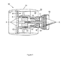
- a ducted fan gas turbine engine generally indicated at 10 has a principal and rotational axis X-X.
- the engine comprises, in axial flow series, an air intake 11, a propulsive fan 12, an intermediate pressure compressor 13, a high-pressure compressor 14, combustion equipment 15, a high-pressure turbine 16, and intermediate pressure turbine 17, a low-pressure turbine 18 and a core engine exhaust nozzle 19.
- a nacelle 21 generally surrounds the engine 10 and defines the intake 11, a bypass duct 22 and a bypass exhaust nozzle 23.
- the gas turbine engine 10 works in a conventional manner so that air entering the intake 11 is accelerated by the fan 12 to produce two air flows: a first air flow A into the intermediate pressure compressor 13 and a second air flow B which passes through the bypass duct 22 to provide propulsive thrust.
- the intermediate pressure compressor 13 compresses the air flow A directed into it before delivering that air to the high pressure compressor 14 where further compression takes place.
- the compressed air exhausted from the high-pressure compressor 14 is directed into the combustion equipment 15 where it is mixed with fuel and the mixture combusted.
- the resultant hot combustion products then expand through, and thereby drive the high, intermediate and low-pressure turbines 16, 17, 18 before being exhausted through the nozzle 19 to provide additional propulsive thrust.
- the high, intermediate and low-pressure turbines respectively drive the high and intermediate pressure compressors 14, 13 and the fan 12 by suitable interconnecting shafts.
- the high pressure turbine components of an aero gas turbine engine are located in the hottest part of the engine. At around 1600°C, the temperature of the gas stream is greater than the melting temperature of the nickel-based alloys from which the high pressure turbine nozzle guide vanes and rotor blades are typically cast.
- cooling air taken from the exit of the high pressure compressor.
- the cooling air which bypasses the combustor, may nonetheless be at a temperature of over 700°C on exit from the compressor section.
- the cooling air even if returned into the flow path of the turbine downstream of the combustor, does not return a full measure of work to the operation of the turbine.
- the greater the amount of cooling air that is extracted the greater the associated loss in engine efficiency.
- One method of reducing the cooling air requirement is to cool the cooling air before it enters the high pressure turbine components. This can be achieved by putting the cooling air in heat exchange relationship with a cooler fluid.
- a cooler fluid For example, many aero gas turbine engines have a bypass air stream which can serve as the cooler fluid. In conventional arrangements, a portion of that air stream is diverted at an offtake into a duct in which the heat exchanger is located. The diverted portion of air, after having passed over the heat exchanger, is then returned to the main bypass air stream.
- US 4254618 proposes bleeding cooling air from the compressor discharge of a turbofan engine, and routing the cooling air to a heat exchanger located in a diffuser section of the fan duct. The cooled cooling air is then routed through compressor rear frame struts to an expander nozzle and thence to the turbine.
- the present invention is at least partly based on a recognition that cooled cooling air systems can be operated more efficiently by taking account of temperatures and/or stresses in the cooled turbine section component.
- the present invention provides a gas turbine engine having, in flow series, a compressor section, a combustor, and a turbine section, and further having:
- the cooled cooling air can be used in a highly efficient manner, thereby improving the overall engine efficiency and/or reducing component temperatures and/or stresses.
- the present invention provides the closed-loop controller of the first aspect.
- the demand signal may be determined on the basis of the comparison and values of the demand signal at plural previous time steps. Indeed, the determination can further be on the basis of plural comparisons, for example at the present time and at previous time steps.
- the engine further may have one or more temperature measuring devices, such as one or more pyrometers or thermocouples, adapted to measure the temperature of the component at one or more locations thereof.
- one or more temperature measuring devices such as one or more pyrometers or thermocouples, adapted to measure the temperature of the component at one or more locations thereof.
- the engine may further have one or more temperature measuring devices, such as thermocouples, adapted to measure at least the temperature of the cooled cooling air and the temperature of the air exiting the compressor section, the closed-loop controller estimating the temperature of the cooled component on the basis of at least the measured temperature of the cooled cooling air and the measured temperature of the air exiting the compressor section.
- one or more temperature measuring devices such as thermocouples, adapted to measure at least the temperature of the cooled cooling air and the temperature of the air exiting the compressor section, the closed-loop controller estimating the temperature of the cooled component on the basis of at least the measured temperature of the cooled cooling air and the measured temperature of the air exiting the compressor section.
- the closed-loop controller may compare the values of the estimated or measured temperatures with one or more corresponding target temperatures.
- the closed-loop controller may calculate one or more stresses in the cooled component based on the estimated and/or measured temperatures, and compare the values of the calculated stresses with one or more corresponding target stresses.
- the closed-loop controller When the closed-loop controller calculates one or more stresses in the cooled component, it may use a reduced order model to calculate the stresses in the component from the estimated and/or measured temperatures. In this way, the stress calculation can be made computationally less intensive, and thus more tractable in real-time.
- the cooled turbine section component is a turbine disc.
- the valve arrangement includes one or more switched vortex valves.
- the heat exchanger is located in a bypass air stream of the engine, such as in the fan duct of a turbofan engine.
- the present invention provides a method of operating a gas turbine engine having, in flow series, a compressor section, a combustor, and a turbine section, the method including the steps of:
- the method of the third aspect thus corresponds to the gas turbine engine of the first aspect, and can be performed using that engine.
- Optional features of the first aspect are applicable singly or in any combination with the third aspect of the invention.
- the comparing step may include comparing the values of the estimated and/or measured temperatures with one or more corresponding target temperatures.
- the method may further include a step of calculating one or more stresses in the cooled component based on the estimated and/or measured temperatures, and the comparing step may include comparing the values of the calculated stresses with one or more corresponding target stresses.
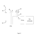
- FIG. 2 shows schematically a conventional system for cooling the high pressure turbine of a turbofan engine using cooled cooling air.
- the system diverts a portion 30 of the high pressure (HP) compressed air exiting of the compressor section at a temperature T30 to one side of a heat exchanger 32 which is located in a side channel of the fan duct.
- the flow rate of the diverted compressed air is controlled by valve 34.
- Low pressure (LP) cooling air 36 at temperature T160 travelling through the fan duct can also be diverted, under the control of valve 38, into the side channel and over the other side of the heat exchanger. This cooling air cools the diverted compressed air (hereafter the "cooled cooling air”) by an amount ⁇ T.
- LP low pressure
- the cooled cooling air is mixed (typically inboard of the combustor) with further portions 40 of the compressed air exiting of the compressor section (at a temperature T30), and then used to cool the high pressure turbine disc and blades.
- the flow rate and the temperature of the cooled cooling air are thus determined by the valves 34, 38, with the settings of the valves 34, 38 being under the control of the engine electronic controller (EEC).
- EEC engine electronic controller
- valve scheduling maps are typically derived based on the performance of a mean new engine using a nominal flight cycle. This leads to sub-optimal scheduling for an in-service engine, which may not fly the nominal flight cycle, and which, with time in service, departs from the performance of the mean new engine.
- the sub-optimal valve scheduling can ultimately reduce disc life.
- the present invention thus provides a different, closed-loop, approach to cooled cooling air control.
- the engine has a cooling system similar to that shown in Figure 2 , but in place of the conventional EEC control of Figure 2 , the system has a closed loop controller as shown schematically in Figure 3(a) .
- the closed-loop controller employs a mean disc temperature sensor 50. This can take the form of a pyrometer measuring a point temperature on the disc, and a processing unit which applies a predetermined functional correlation to convert the point temperature to a mean temperature.
- the measured temperature is compared in a comparator 54 with corresponding desired temperature target, which is typically calculated off-line as a function of, for example, engine power, altitude, ambient temperature and Mach number.
- desired temperature target typically calculated off-line as a function of, for example, engine power, altitude, ambient temperature and Mach number.
- the resulting error value is sent to a control unit 56, which determines therefrom appropriate demand signals to be sent to the valves controlling the flow rates of the HP compressed air and LP cooling air sent to the heat exchanger according to engine conditions to control disc temperatures.
- the demand signals can be calculated in the control unit 56 by defining a transfer function that acts on the error.
- the control unit implements closed-loop multivariable control.
- the demand signals issued by the control unit at previous time steps are also used by the unit to determine the current demand signals.
- the control unit can implement a simple PI controller or a more sophisticated transfer function of a type known to the skilled person
- FIG. 3(b) shows schematically a closed loop controller according to a second embodiment.
- the second embodiment differs from the first embodiment by measuring engine variables from which the disc temperature can be estimated in an estimating unit 50' rather than measuring the disc temperature directly.
- thermocouples can measure at least the temperatures: (i) T HX of the flow of cooled cooling air exiting the heat exchanger, (ii) T 30 of the flow of high pressure air exiting the compressor section, and (iii) T 26 of the flow of inlet air to the HP compressor (some of which flow is diverted to cool the disc bore).
- the two air flows (i) and (ii) are mixed in different proportions in two air streams by respective pre-swirler nozzles (A and B) before being used to cool the high pressure turbine disc and blades.
- the measured temperatures T HX and T 30 can be functionally correlated with e.g. the high pressure turbine speed N 3 and the altitude ALT to provide the temperatures T A , T B of the respective resultant coolant flows:
- T A f T HX ⁇ T 30 ⁇ N 3 ⁇ ALT
- T B g T HX ⁇ T 30 ⁇ N 3 ⁇ ALT
- T ⁇ disc F T A ⁇ T B ⁇ T 30 ⁇ N 3 ⁇ ALT
- the functional relations f, g and F are, in general, not simply algebraic equations of input parameters, but rather sets of dynamic differential equations that relate the time variation of the inputs to the mean disc temperature, i.e. the functions f, g and F are normally state-space models of types known to the skilled person.
- the estimated mean temperature is then used in a disc stress calculator unit 52 to calculate one or more stresses in the disc based on the estimated mean temperature. The stress calculation is discussed further below.
- the calculated stresses are compared in a comparator 54 with corresponding desired stress targets, which are typically calculated off-line as a function of, for example, engine power, altitude, ambient temperature and Mach number.
- the resulting one or more error values are sent to a control unit 56, which determines therefrom appropriate demand signals to be sent to the valves controlling the flow rates of the HP compressed air and LP cooling air sent to the heat exchanger.
- Figure 4 shows schematically a closed loop controller according to a third embodiment.
- the third embodiment is similar to the second embodiment.
- the measured engine variables can again include the temperatures T HX , T 30 (from which T A , T B can be determined, as discussed above) and T 26 .
- a disc stress calculator unit 52 calculates one or more stresses in the disc based on estimated temperatures in the disc.
- the controller 56 can then adjust the flow of cooled cooling air according to engine conditions to control disc stress.
- the stress calculation can be accomplished using a reduced order model.
- the matrix B can be derived by applying Dirichlet and/or Neumann boundary conditions to the surface of the discretized disc.
- the state-space model has a large number of states, depending on the number of finite volume elements over which the disc discretized, and can thus be computationally very intensive. This can lead to difficulties in the real-time implementation.
- We can thus define the stress output variables by: ⁇ C ⁇ x where ⁇ are the output stresses at selected life limiting points on the disc, and C is a matrix of coefficients. For example, if it is desired to know the local thermal stress between two adjacent volume elements, then the stress may be determined as a constant times the temperature difference between the two elements.
- control unit 56 can implement a simple PI controller or a more sophisticated transfer function.
- another option which may be particularly advantageous when a number of stress states are calculated, is to integrate functions of the comparator 54 and control unit 56 such that a state-feedback controller, e.g. incorporating a Kalman filter, acts directly on the stress states from the stress model.
- a feedback gain matrix can be derived using LQR/LQG methodology and applied to state vector to determine the valve settings.
- the disc can be e.g. operated at close to optimal conditions, helping to improve the overall efficiency of the engine, or cooled more effectively for the same amount of cooling air, allowing the engine to be operated to be run for longer before each off-wing overhaul.
Landscapes
- Engineering & Computer Science (AREA)
- Mechanical Engineering (AREA)
- General Engineering & Computer Science (AREA)
- Chemical & Material Sciences (AREA)
- Combustion & Propulsion (AREA)
- Physics & Mathematics (AREA)
- Fluid Mechanics (AREA)
- Control Of Turbines (AREA)
- Control Of Temperature (AREA)
Abstract
Description
- The present invention relates to a closed-loop controller, and, in particular, to a gas turbine engine having a system including such a controller for cooling the turbine section of the gas turbine.
- With reference to
Figure 1 , a ducted fan gas turbine engine generally indicated at 10 has a principal and rotational axis X-X. The engine comprises, in axial flow series, anair intake 11, apropulsive fan 12, anintermediate pressure compressor 13, a high-pressure compressor 14,combustion equipment 15, a high-pressure turbine 16, andintermediate pressure turbine 17, a low-pressure turbine 18 and a coreengine exhaust nozzle 19. Anacelle 21 generally surrounds theengine 10 and defines theintake 11, abypass duct 22 and abypass exhaust nozzle 23. - The
gas turbine engine 10 works in a conventional manner so that air entering theintake 11 is accelerated by thefan 12 to produce two air flows: a first air flow A into theintermediate pressure compressor 13 and a second air flow B which passes through thebypass duct 22 to provide propulsive thrust. Theintermediate pressure compressor 13 compresses the air flow A directed into it before delivering that air to thehigh pressure compressor 14 where further compression takes place. - The compressed air exhausted from the high-
pressure compressor 14 is directed into thecombustion equipment 15 where it is mixed with fuel and the mixture combusted. The resultant hot combustion products then expand through, and thereby drive the high, intermediate and low-pressure turbines nozzle 19 to provide additional propulsive thrust. The high, intermediate and low-pressure turbines respectively drive the high andintermediate pressure compressors fan 12 by suitable interconnecting shafts. - The high pressure turbine components of an aero gas turbine engine are located in the hottest part of the engine. At around 1600°C, the temperature of the gas stream is greater than the melting temperature of the nickel-based alloys from which the high pressure turbine nozzle guide vanes and rotor blades are typically cast.
- It is usual, therefore, to cool nozzle guide vanes and rotor blades internally using cooling air taken from the exit of the high pressure compressor. The cooling air, which bypasses the combustor, may nonetheless be at a temperature of over 700°C on exit from the compressor section. However, the cooling air, even if returned into the flow path of the turbine downstream of the combustor, does not return a full measure of work to the operation of the turbine. Thus, the greater the amount of cooling air that is extracted, the greater the associated loss in engine efficiency.
- One method of reducing the cooling air requirement is to cool the cooling air before it enters the high pressure turbine components. This can be achieved by putting the cooling air in heat exchange relationship with a cooler fluid. For example, many aero gas turbine engines have a bypass air stream which can serve as the cooler fluid. In conventional arrangements, a portion of that air stream is diverted at an offtake into a duct in which the heat exchanger is located. The diverted portion of air, after having passed over the heat exchanger, is then returned to the main bypass air stream.
-
US 4254618 proposes bleeding cooling air from the compressor discharge of a turbofan engine, and routing the cooling air to a heat exchanger located in a diffuser section of the fan duct. The cooled cooling air is then routed through compressor rear frame struts to an expander nozzle and thence to the turbine. - It would be desirable to increase the efficiency of engines have cooled cooling air systems.
- The present invention is at least partly based on a recognition that cooled cooling air systems can be operated more efficiently by taking account of temperatures and/or stresses in the cooled turbine section component.
- Accordingly, in a first aspect, the present invention provides a gas turbine engine having, in flow series, a compressor section, a combustor, and a turbine section, and further having:
- a cooling system which diverts a cooling air flow received from the compressor section to a heat exchanger and then to the turbine section to cool a component thereof, the cooling air flow by-passing the combustor and being cooled in the heat exchanger, and the cooling system having a valve arrangement which regulates the cooling air flow; and
- a closed-loop controller which estimates and/or measures one or more temperatures of the cooled component, compares values derived from the estimated and/or measured temperatures with one or more corresponding targets, and issues a demand signal to the valve arrangement based on the comparison and a value of the demand signal at a previous time step.
- Advantageously, by controlling the cooled cooling air on the basis of such a comparison, the cooled cooling air can be used in a highly efficient manner, thereby improving the overall engine efficiency and/or reducing component temperatures and/or stresses.
- In a second aspect, the present invention provides the closed-loop controller of the first aspect.
- Optional features of the invention will now be set out. These are applicable singly or in any combination with any of the above aspects of the invention.
- Typically, the demand signal may be determined on the basis of the comparison and values of the demand signal at plural previous time steps. Indeed, the determination can further be on the basis of plural comparisons, for example at the present time and at previous time steps.
- When the closed-loop controller measures the temperature of the cooled component, the engine further may have one or more temperature measuring devices, such as one or more pyrometers or thermocouples, adapted to measure the temperature of the component at one or more locations thereof.
- Alternatively or additionally, the engine may further have one or more temperature measuring devices, such as thermocouples, adapted to measure at least the temperature of the cooled cooling air and the temperature of the air exiting the compressor section, the closed-loop controller estimating the temperature of the cooled component on the basis of at least the measured temperature of the cooled cooling air and the measured temperature of the air exiting the compressor section.
- According to one option, the closed-loop controller may compare the values of the estimated or measured temperatures with one or more corresponding target temperatures. However, according to another option, the closed-loop controller may calculate one or more stresses in the cooled component based on the estimated and/or measured temperatures, and compare the values of the calculated stresses with one or more corresponding target stresses.
- When the closed-loop controller calculates one or more stresses in the cooled component, it may use a reduced order model to calculate the stresses in the component from the estimated and/or measured temperatures. In this way, the stress calculation can be made computationally less intensive, and thus more tractable in real-time.
- Preferably, the cooled turbine section component is a turbine disc.
- Preferably, the valve arrangement includes one or more switched vortex valves.
- Preferably, the heat exchanger is located in a bypass air stream of the engine, such as in the fan duct of a turbofan engine.
- In a third aspect, the present invention provides a method of operating a gas turbine engine having, in flow series, a compressor section, a combustor, and a turbine section, the method including the steps of:
- diverting a cooling air flow received from the compressor section to a heat exchanger and then to the turbine section to cool a component thereof, the cooling air flow by-passing the combustor and being cooled in the heat exchanger;
- estimating and/or measuring one or more temperatures of the cooled component; comparing values derived from the estimated and/or measured temperatures with one or more corresponding targets; and
- issuing a demand signal to the valve arrangement based on the comparison and a value of the demand signal at a previous time step.
- The method of the third aspect thus corresponds to the gas turbine engine of the first aspect, and can be performed using that engine. Optional features of the first aspect are applicable singly or in any combination with the third aspect of the invention.
- For example, according to one option, the comparing step may include comparing the values of the estimated and/or measured temperatures with one or more corresponding target temperatures. According to another option, the method may further include a step of calculating one or more stresses in the cooled component based on the estimated and/or measured temperatures, and the comparing step may include comparing the values of the calculated stresses with one or more corresponding target stresses.
- Further optional features of the invention are set out below.
- Embodiments of the invention will now be described by way of example with reference to the accompanying drawings in which:
-
Figure 1 shows a schematic longitudinal cross-section through a ducted fan gas turbine engine; -
Figure 2 shows schematically a conventional system for cooling the high pressure turbine of a turbofan engine using cooled cooling air; -
Figure 3 shows schematically closed-loop controllers according to (a) first and (b) second embodiments of the present invention; -
Figure 4 shows schematically closed-loop controllers according to a third embodiment of the present invention; and -
Figure 5 shows schematically a volume element of a discretized turbine disc. -
Figure 2 shows schematically a conventional system for cooling the high pressure turbine of a turbofan engine using cooled cooling air. The system diverts aportion 30 of the high pressure (HP) compressed air exiting of the compressor section at a temperature T30 to one side of aheat exchanger 32 which is located in a side channel of the fan duct. The flow rate of the diverted compressed air is controlled byvalve 34. Low pressure (LP) coolingair 36 at temperature T160 travelling through the fan duct can also be diverted, under the control ofvalve 38, into the side channel and over the other side of the heat exchanger. This cooling air cools the diverted compressed air (hereafter the "cooled cooling air") by an amount ΔT. - The cooled cooling air is mixed (typically inboard of the combustor) with
further portions 40 of the compressed air exiting of the compressor section (at a temperature T30), and then used to cool the high pressure turbine disc and blades. The flow rate and the temperature of the cooled cooling air are thus determined by thevalves valves - These settings can be derived using engine performance decks. However, a disadvantage of this approach is that the overall system is open-loop. The valve scheduling maps are typically derived based on the performance of a mean new engine using a nominal flight cycle. This leads to sub-optimal scheduling for an in-service engine, which may not fly the nominal flight cycle, and which, with time in service, departs from the performance of the mean new engine. The sub-optimal valve scheduling can ultimately reduce disc life.
- The present invention thus provides a different, closed-loop, approach to cooled cooling air control. In a first embodiment, the engine has a cooling system similar to that shown in
Figure 2 , but in place of the conventional EEC control ofFigure 2 , the system has a closed loop controller as shown schematically inFigure 3(a) . The closed-loop controller employs a meandisc temperature sensor 50. This can take the form of a pyrometer measuring a point temperature on the disc, and a processing unit which applies a predetermined functional correlation to convert the point temperature to a mean temperature. - Next, the measured temperature is compared in a
comparator 54 with corresponding desired temperature target, which is typically calculated off-line as a function of, for example, engine power, altitude, ambient temperature and Mach number. The resulting error value is sent to acontrol unit 56, which determines therefrom appropriate demand signals to be sent to the valves controlling the flow rates of the HP compressed air and LP cooling air sent to the heat exchanger according to engine conditions to control disc temperatures. - The demand signals can be calculated in the
control unit 56 by defining a transfer function that acts on the error. However, the control unit implements closed-loop multivariable control. Thus the demand signals issued by the control unit at previous time steps are also used by the unit to determine the current demand signals. The control unit can implement a simple PI controller or a more sophisticated transfer function of a type known to the skilled person -
Figure 3(b) shows schematically a closed loop controller according to a second embodiment. The second embodiment differs from the first embodiment by measuring engine variables from which the disc temperature can be estimated in an estimating unit 50' rather than measuring the disc temperature directly. Thus, for example, thermocouples can measure at least the temperatures: (i) THX of the flow of cooled cooling air exiting the heat exchanger, (ii) T30 of the flow of high pressure air exiting the compressor section, and (iii) T26 of the flow of inlet air to the HP compressor (some of which flow is diverted to cool the disc bore). Typically the two air flows (i) and (ii) are mixed in different proportions in two air streams by respective pre-swirler nozzles (A and B) before being used to cool the high pressure turbine disc and blades. For each pre-swirler nozzle, the measured temperatures THX and T30 can be functionally correlated with e.g. the high pressure turbine speed N3 and the altitude ALT to provide the temperatures TA, TB of the respective resultant coolant flows:

- The coolant flows from both the pre-swirler nozzles and the flow (iii) impinge on the turbine disc and can thus be used in a pre-determined correlation to compute the real-time actual mean disc temperature
T̅ disc :
- Other engine parameters and measured variables can also be used to estimate a mean disc temperature. The functional relations f, g and F are, in general, not simply algebraic equations of input parameters, but rather sets of dynamic differential equations that relate the time variation of the inputs to the mean disc temperature, i.e. the functions f, g and F are normally state-space models of types known to the skilled person.
- It is also possible to combine the approaches of the first and second embodiments so that the disc temperature is determined from both direct and indirect measurements.
- The estimated mean temperature is then used in a disc
stress calculator unit 52 to calculate one or more stresses in the disc based on the estimated mean temperature. The stress calculation is discussed further below. - Next, the calculated stresses are compared in a
comparator 54 with corresponding desired stress targets, which are typically calculated off-line as a function of, for example, engine power, altitude, ambient temperature and Mach number. The resulting one or more error values are sent to acontrol unit 56, which determines therefrom appropriate demand signals to be sent to the valves controlling the flow rates of the HP compressed air and LP cooling air sent to the heat exchanger. -
Figure 4 shows schematically a closed loop controller according to a third embodiment. The third embodiment is similar to the second embodiment. Thus, the measured engine variables can again include the temperatures THX, T30 (from which TA, TB can be determined, as discussed above) and T26. However, in the third embodiment, a discstress calculator unit 52 calculates one or more stresses in the disc based on estimated temperatures in the disc. Thecontroller 56 can then adjust the flow of cooled cooling air according to engine conditions to control disc stress. The stress calculation can be accomplished using a reduced order model. Considering a finite thermal model:
where T is temperature, t is time, α is thermal diffusivity, q̇ is heat flow rate, ρ is density and c is specific heat capacity, integrating over the volume of the disc yields:
- Applying divergence theorem simplifies the above to:

- The disc is axisymmetric and thus in a volume element of the discretized disc it is only necessary two consider two dimensions. The temperature of such a volume element, Vi,j, (shown schematically in
Figure 4 ) is given by:
where k is thermal conductivity. Such a model, together with the boundary conditions on the blade geometry, can form a large dimensional state-space model of the type:
where:

- The state-space model has a large number of states, depending on the number of finite volume elements over which the disc discretized, and can thus be computationally very intensive. This can lead to difficulties in the real-time implementation. However, we are not necessarily interested in the temperatures of all the volume elements but rather in stresses at specific life limiting points on the disc caused by the disc temperatures. We can thus define the stress output variables by:

where σ are the output stresses at selected life limiting points on the disc, and C is a matrix of coefficients. For example, if it is desired to know the local thermal stress between two adjacent volume elements, then the stress may be determined as a constant times the temperature difference between the two elements. - Applying a model reduction technique, of a type known to the skilled person, to the system defined by (1) and (2) allows the derivation of a suitable reduced order model that predicts with reasonable accuracy the disc temperature distribution and thermal stresses at points corresponding to the σ = C x relationship.
- As with the previous embodiments, the
control unit 56 can implement a simple PI controller or a more sophisticated transfer function. However, another option, which may be particularly advantageous when a number of stress states are calculated, is to integrate functions of thecomparator 54 andcontrol unit 56 such that a state-feedback controller, e.g. incorporating a Kalman filter, acts directly on the stress states from the stress model. A feedback gain matrix can be derived using LQR/LQG methodology and applied to state vector to determine the valve settings. - Overall, by regulating the cooled cooling air flow on the basis of measured or estimated disc temperatures, or on the basis of stresses at life limiting points on the disc, the disc can be e.g. operated at close to optimal conditions, helping to improve the overall efficiency of the engine, or cooled more effectively for the same amount of cooling air, allowing the engine to be operated to be run for longer before each off-wing overhaul.
- While the invention has been described in conjunction with the exemplary embodiments described above, many equivalent modifications and variations will be apparent to those skilled in the art when given this disclosure. Accordingly, the exemplary embodiments of the invention set forth above are considered to be illustrative and not limiting. Various changes to the described embodiments may be made without departing from the spirit and scope of the invention.
- All references referred to above are hereby incorporated by reference.
Claims (13)
- A gas turbine engine having, in flow series, a compressor section, a combustor, and a turbine section, and further having:a cooling system which diverts a cooling air flow received from the compressor section to a heat exchanger and then to the turbine section to cool a component thereof, the cooling air flow by-passing the combustor and being cooled in the heat exchanger, and the cooling system having a valve arrangement which regulates the cooling air flow; anda closed-loop controller which estimates and/or measures one or more temperatures of the cooled component, compares values derived from the estimated and/or measured temperatures with one or more corresponding targets, and issues a demand signal to the valve arrangement based on the comparison and a value of the demand signal at a previous time step.
- A gas turbine engine according to claim 1, wherein the closed-loop controller measures the temperature of the cooled component, the engine further having one or more temperature measuring devices adapted to measure the temperature of the component at one or more locations thereof.
- A gas turbine engine according to claim 1 or 2, wherein the engine further has one or more temperature measuring devices adapted to measure at least the temperature of the cooled cooling air and the temperature of the air exiting the compressor section, the closed-loop controller estimating the temperature of the cooled component on the basis of at least the measured temperature of the cooled cooling air and the measured temperature of the air exiting the compressor section.
- A gas turbine engine according to any one of the previous claims, wherein the closed-loop controller compares the values of the estimated or measured temperatures with one or more corresponding target temperatures.
- A gas turbine engine according to any one of the previous claims, wherein the closed-loop controller calculates one or more stresses in the cooled component based on the estimated and/or measured temperatures, and compares the values of the calculated stresses with one or more corresponding target stresses.
- A gas turbine engine according to claim 5, wherein the closed-loop controller uses a reduced order model to calculate the stresses in the component from the estimated and/or measured temperatures.
- A gas turbine engine according to any one of the previous claims, wherein the cooled component is a turbine disc.
- A gas turbine engine according to any one of the previous claims, wherein the valve arrangement includes one or more switched vortex valves.
- A gas turbine engine according to any one of the previous claims, wherein the heat exchanger is located in a bypass air stream of the engine.
- The closed-loop controller of any one of claims 1 to 9.
- A method of operating a gas turbine engine having, in flow series, a compressor section, a combustor, and a turbine section, the method including the steps of:diverting a cooling air flow received from the compressor section to a heat exchanger and then to the turbine section to cool a component thereof, the cooling air flow by-passing the combustor and being cooled in the heat exchanger;estimating and/or measuring one or more temperatures of the cooled component; comparing values derived from the estimated and/or measured temperatures with one or more corresponding targets; andissuing a demand signal to the valve arrangement based on the comparison and a value of the demand signal at a previous time step.
- A method according to claim 11, wherein the comparing step includes comparing the values of the estimated and/or measured temperatures with one or more corresponding target temperatures.
- A method according to claim 11, further including a step of:calculating one or more stresses in the cooled component based on the estimated and/or measured temperatures; andwherein the comparing step includes comparing the values of the calculated stresses with one or more corresponding target stresses.
Applications Claiming Priority (1)
| Application Number | Priority Date | Filing Date | Title |
|---|---|---|---|
| GBGB1121428.5A GB201121428D0 (en) | 2011-12-14 | 2011-12-14 | Controller |
Publications (3)
| Publication Number | Publication Date |
|---|---|
| EP2604825A2 true EP2604825A2 (en) | 2013-06-19 |
| EP2604825A3 EP2604825A3 (en) | 2015-03-04 |
| EP2604825B1 EP2604825B1 (en) | 2017-04-26 |
Family
ID=45560400
Family Applications (1)
| Application Number | Title | Priority Date | Filing Date |
|---|---|---|---|
| EP12193315.4A Active EP2604825B1 (en) | 2011-12-14 | 2012-11-20 | Controller for cooling the turbine section of a gas turbine engine |
Country Status (3)
| Country | Link |
|---|---|
| US (1) | US9249729B2 (en) |
| EP (1) | EP2604825B1 (en) |
| GB (1) | GB201121428D0 (en) |
Cited By (29)
| Publication number | Priority date | Publication date | Assignee | Title |
|---|---|---|---|---|
| CN104632303A (en) * | 2014-12-30 | 2015-05-20 | 北京华清燃气轮机与煤气化联合循环工程技术有限公司 | Automatic intelligent cooling system and method of gas turbine |
| FR3025835A1 (en) * | 2014-09-16 | 2016-03-18 | Snecma | TURBOMACHINE TURBINE AUB COOLING AIR CIRCULATION SYSTEM |
| EP3018288A1 (en) * | 2014-11-05 | 2016-05-11 | United Technologies Corporation | High pressure compressor rotor thermal conditioning using discharge pressure air |
| EP3085924A1 (en) * | 2015-04-24 | 2016-10-26 | United Technologies Corporation | Cooling air intercooling with cooling air tapped from plural locations |
| US9624832B2 (en) | 2013-05-16 | 2017-04-18 | Rolls-Royce Plc | Heat exchange arrangement |
| EP3168428A1 (en) * | 2015-10-21 | 2017-05-17 | Rolls-Royce plc | A system and method of calibrating case cooling for a gas turbine engine |
| EP3232032A1 (en) * | 2016-04-13 | 2017-10-18 | United Technologies Corporation | Cooling air architecture for compact size and performance improvement |
| US10100739B2 (en) | 2015-05-18 | 2018-10-16 | United Technologies Corporation | Cooled cooling air system for a gas turbine engine |
| US10371055B2 (en) | 2015-02-12 | 2019-08-06 | United Technologies Corporation | Intercooled cooling air using cooling compressor as starter |
| US10443508B2 (en) | 2015-12-14 | 2019-10-15 | United Technologies Corporation | Intercooled cooling air with auxiliary compressor control |
| EP3557029A1 (en) * | 2018-04-19 | 2019-10-23 | United Technologies Corporation | Intercooled cooling air fleet management system |
| US10480419B2 (en) | 2015-04-24 | 2019-11-19 | United Technologies Corporation | Intercooled cooling air with plural heat exchangers |
| US10550768B2 (en) | 2016-11-08 | 2020-02-04 | United Technologies Corporation | Intercooled cooled cooling integrated air cycle machine |
| US10577964B2 (en) | 2017-03-31 | 2020-03-03 | United Technologies Corporation | Cooled cooling air for blade air seal through outer chamber |
| US10669940B2 (en) | 2016-09-19 | 2020-06-02 | Raytheon Technologies Corporation | Gas turbine engine with intercooled cooling air and turbine drive |
| US10711640B2 (en) | 2017-04-11 | 2020-07-14 | Raytheon Technologies Corporation | Cooled cooling air to blade outer air seal passing through a static vane |
| US10718233B2 (en) | 2018-06-19 | 2020-07-21 | Raytheon Technologies Corporation | Intercooled cooling air with low temperature bearing compartment air |
| US10731560B2 (en) | 2015-02-12 | 2020-08-04 | Raytheon Technologies Corporation | Intercooled cooling air |
| US10738703B2 (en) | 2018-03-22 | 2020-08-11 | Raytheon Technologies Corporation | Intercooled cooling air with combined features |
| US10794288B2 (en) | 2015-07-07 | 2020-10-06 | Raytheon Technologies Corporation | Cooled cooling air system for a turbofan engine |
| US10794290B2 (en) | 2016-11-08 | 2020-10-06 | Raytheon Technologies Corporation | Intercooled cooled cooling integrated air cycle machine |
| US10808619B2 (en) | 2018-04-19 | 2020-10-20 | Raytheon Technologies Corporation | Intercooled cooling air with advanced cooling system |
| US10830148B2 (en) | 2015-04-24 | 2020-11-10 | Raytheon Technologies Corporation | Intercooled cooling air with dual pass heat exchanger |
| US10961911B2 (en) | 2017-01-17 | 2021-03-30 | Raytheon Technologies Corporation | Injection cooled cooling air system for a gas turbine engine |
| US10995673B2 (en) | 2017-01-19 | 2021-05-04 | Raytheon Technologies Corporation | Gas turbine engine with intercooled cooling air and dual towershaft accessory gearbox |
| US11255268B2 (en) | 2018-07-31 | 2022-02-22 | Raytheon Technologies Corporation | Intercooled cooling air with selective pressure dump |
| US11808210B2 (en) | 2015-02-12 | 2023-11-07 | Rtx Corporation | Intercooled cooling air with heat exchanger packaging |
| EP4283093A1 (en) * | 2022-05-27 | 2023-11-29 | Aurelia Turbines Oy | Turbine wheel, gas turbine, and method for cooling a turbine wheel |
| CN118939051A (en) * | 2024-10-12 | 2024-11-12 | 国网安徽省电力有限公司电力科学研究院 | Operation control method for multi-energy comprehensive utilization of distributed compressed air energy storage system |
Families Citing this family (10)
| Publication number | Priority date | Publication date | Assignee | Title |
|---|---|---|---|---|
| GB2516048A (en) * | 2013-07-09 | 2015-01-14 | Rolls Royce Plc | Tip clearance control method |
| US20150118014A1 (en) * | 2013-10-29 | 2015-04-30 | General Electric Company | Setting Gas Turbine Firing to Maintain Metal Surface Temperatures |
| JP6320063B2 (en) * | 2014-02-03 | 2018-05-09 | 三菱日立パワーシステムズ株式会社 | Gas turbine, gas turbine control device, and gas turbine cooling method |
| US11578668B2 (en) | 2017-05-30 | 2023-02-14 | Raytheon Technologies Corporation | Gas turbine engine control based on characteristic of cooled air |
| JP6252819B1 (en) * | 2017-09-26 | 2017-12-27 | 三菱日立パワーシステムズ株式会社 | Control device, gas turbine, control method and program |
| GB201804128D0 (en) * | 2018-03-15 | 2018-05-02 | Rolls Royce Plc | Electrical power generator system |
| JP7129810B2 (en) * | 2018-04-13 | 2022-09-02 | 三菱重工業株式会社 | Valve opening determining device for cooling air control valve, disk cavity target temperature determining device, and disk cavity temperature control device |
| US11578667B2 (en) | 2018-08-30 | 2023-02-14 | Rolls-Royce Corporation | Efficiency-based machine control |
| US11946378B2 (en) | 2022-04-13 | 2024-04-02 | General Electric Company | Transient control of a thermal transport bus |
| US11927142B2 (en) | 2022-07-25 | 2024-03-12 | General Electric Company | Systems and methods for controlling fuel coke formation |
Family Cites Families (16)
| Publication number | Priority date | Publication date | Assignee | Title |
|---|---|---|---|---|
| US4254618A (en) * | 1977-08-18 | 1981-03-10 | General Electric Company | Cooling air cooler for a gas turbofan engine |
| JPS62182444A (en) * | 1986-02-07 | 1987-08-10 | Hitachi Ltd | Gas turbine cooling air control method and device |
| US4999991A (en) | 1989-10-12 | 1991-03-19 | United Technologies Corporation | Synthesized feedback for gas turbine clearance control |
| US5224332A (en) | 1990-12-27 | 1993-07-06 | Schwarz Frederick M | Modulated gas turbine cooling air |
| US6792762B1 (en) * | 1999-11-10 | 2004-09-21 | Hitachi, Ltd. | Gas turbine equipment and gas turbine cooling method |
| US6584778B1 (en) * | 2000-05-11 | 2003-07-01 | General Electric Co. | Methods and apparatus for supplying cooling air to turbine engines |
| US6694742B2 (en) * | 2002-06-26 | 2004-02-24 | General Electric Company | Gas turbine system operation based on estimated stress |
| GB0609312D0 (en) * | 2006-05-11 | 2006-06-21 | Rolls Royce Plc | Clearance Control Apparatus |
| US7823389B2 (en) * | 2006-11-15 | 2010-11-02 | General Electric Company | Compound clearance control engine |
| US8015824B2 (en) | 2007-05-01 | 2011-09-13 | General Electric Company | Method and system for regulating a cooling fluid within a turbomachine in real time |
| GB0804002D0 (en) * | 2008-03-04 | 2008-04-09 | Rolls Royce Plc | A flow control arrangement |
| US8240153B2 (en) | 2008-05-14 | 2012-08-14 | General Electric Company | Method and system for controlling a set point for extracting air from a compressor to provide turbine cooling air in a gas turbine |
| US8355854B2 (en) | 2009-05-08 | 2013-01-15 | General Electric Company | Methods relating to gas turbine control and operation |
| US8538561B2 (en) * | 2011-03-22 | 2013-09-17 | General Electric Company | Method and system to estimate variables in an integrated gasification combined cycle (IGCC) plant |
| GB201121426D0 (en) * | 2011-12-14 | 2012-01-25 | Rolls Royce Plc | Controller |
| US20140126991A1 (en) * | 2012-11-07 | 2014-05-08 | General Electric Company | Systems and methods for active component life management for gas turbine engines |
-
2011
- 2011-12-14 GB GBGB1121428.5A patent/GB201121428D0/en not_active Ceased
-
2012
- 2012-11-20 EP EP12193315.4A patent/EP2604825B1/en active Active
- 2012-11-20 US US13/682,280 patent/US9249729B2/en active Active
Cited By (44)
| Publication number | Priority date | Publication date | Assignee | Title |
|---|---|---|---|---|
| US9624832B2 (en) | 2013-05-16 | 2017-04-18 | Rolls-Royce Plc | Heat exchange arrangement |
| FR3025835A1 (en) * | 2014-09-16 | 2016-03-18 | Snecma | TURBOMACHINE TURBINE AUB COOLING AIR CIRCULATION SYSTEM |
| EP3018288A1 (en) * | 2014-11-05 | 2016-05-11 | United Technologies Corporation | High pressure compressor rotor thermal conditioning using discharge pressure air |
| US10107206B2 (en) | 2014-11-05 | 2018-10-23 | United Technologies Corporation | High pressure compressor rotor thermal conditioning using discharge pressure air |
| CN104632303B (en) * | 2014-12-30 | 2017-07-07 | 北京华清燃气轮机与煤气化联合循环工程技术有限公司 | The automated intelligent cooling system and method for a kind of gas turbine turbine |
| CN104632303A (en) * | 2014-12-30 | 2015-05-20 | 北京华清燃气轮机与煤气化联合循环工程技术有限公司 | Automatic intelligent cooling system and method of gas turbine |
| US10830149B2 (en) | 2015-02-12 | 2020-11-10 | Raytheon Technologies Corporation | Intercooled cooling air using cooling compressor as starter |
| US10731560B2 (en) | 2015-02-12 | 2020-08-04 | Raytheon Technologies Corporation | Intercooled cooling air |
| US11808210B2 (en) | 2015-02-12 | 2023-11-07 | Rtx Corporation | Intercooled cooling air with heat exchanger packaging |
| US10371055B2 (en) | 2015-02-12 | 2019-08-06 | United Technologies Corporation | Intercooled cooling air using cooling compressor as starter |
| US10830148B2 (en) | 2015-04-24 | 2020-11-10 | Raytheon Technologies Corporation | Intercooled cooling air with dual pass heat exchanger |
| EP3085924A1 (en) * | 2015-04-24 | 2016-10-26 | United Technologies Corporation | Cooling air intercooling with cooling air tapped from plural locations |
| US10221862B2 (en) | 2015-04-24 | 2019-03-05 | United Technologies Corporation | Intercooled cooling air tapped from plural locations |
| US11215197B2 (en) | 2015-04-24 | 2022-01-04 | Raytheon Technologies Corporation | Intercooled cooling air tapped from plural locations |
| US10480419B2 (en) | 2015-04-24 | 2019-11-19 | United Technologies Corporation | Intercooled cooling air with plural heat exchangers |
| US10914235B2 (en) | 2015-05-18 | 2021-02-09 | Raytheon Technologies Corporation | Cooled cooling air system for a gas turbine engine |
| US10100739B2 (en) | 2015-05-18 | 2018-10-16 | United Technologies Corporation | Cooled cooling air system for a gas turbine engine |
| US10794288B2 (en) | 2015-07-07 | 2020-10-06 | Raytheon Technologies Corporation | Cooled cooling air system for a turbofan engine |
| US10626800B2 (en) | 2015-10-21 | 2020-04-21 | Rolls-Royce Plc | System and method for calibrating a case cooling system for a gas turbine engine |
| EP3168428A1 (en) * | 2015-10-21 | 2017-05-17 | Rolls-Royce plc | A system and method of calibrating case cooling for a gas turbine engine |
| US11002195B2 (en) | 2015-12-14 | 2021-05-11 | Raytheon Technologies Corporation | Intercooled cooling air with auxiliary compressor control |
| US10443508B2 (en) | 2015-12-14 | 2019-10-15 | United Technologies Corporation | Intercooled cooling air with auxiliary compressor control |
| US11512651B2 (en) | 2015-12-14 | 2022-11-29 | Raytheon Technologies Corporation | Intercooled cooling air with auxiliary compressor control |
| US10760492B2 (en) | 2016-04-13 | 2020-09-01 | Raytheon Technologies Corporation | Cooling air architecture for compact size and performance improvement |
| EP3232032A1 (en) * | 2016-04-13 | 2017-10-18 | United Technologies Corporation | Cooling air architecture for compact size and performance improvement |
| US10669940B2 (en) | 2016-09-19 | 2020-06-02 | Raytheon Technologies Corporation | Gas turbine engine with intercooled cooling air and turbine drive |
| US11236675B2 (en) | 2016-09-19 | 2022-02-01 | Raytheon Technologies Corporation | Gas turbine engine with intercooled cooling air and turbine drive |
| US10550768B2 (en) | 2016-11-08 | 2020-02-04 | United Technologies Corporation | Intercooled cooled cooling integrated air cycle machine |
| US10794290B2 (en) | 2016-11-08 | 2020-10-06 | Raytheon Technologies Corporation | Intercooled cooled cooling integrated air cycle machine |
| US10961911B2 (en) | 2017-01-17 | 2021-03-30 | Raytheon Technologies Corporation | Injection cooled cooling air system for a gas turbine engine |
| US10995673B2 (en) | 2017-01-19 | 2021-05-04 | Raytheon Technologies Corporation | Gas turbine engine with intercooled cooling air and dual towershaft accessory gearbox |
| US10577964B2 (en) | 2017-03-31 | 2020-03-03 | United Technologies Corporation | Cooled cooling air for blade air seal through outer chamber |
| US11773742B2 (en) | 2017-03-31 | 2023-10-03 | Rtx Corporation | Cooled cooling air for blade air seal through outer chamber |
| US10711640B2 (en) | 2017-04-11 | 2020-07-14 | Raytheon Technologies Corporation | Cooled cooling air to blade outer air seal passing through a static vane |
| US10738703B2 (en) | 2018-03-22 | 2020-08-11 | Raytheon Technologies Corporation | Intercooled cooling air with combined features |
| US10808619B2 (en) | 2018-04-19 | 2020-10-20 | Raytheon Technologies Corporation | Intercooled cooling air with advanced cooling system |
| EP3557029A1 (en) * | 2018-04-19 | 2019-10-23 | United Technologies Corporation | Intercooled cooling air fleet management system |
| US10830145B2 (en) | 2018-04-19 | 2020-11-10 | Raytheon Technologies Corporation | Intercooled cooling air fleet management system |
| US10718233B2 (en) | 2018-06-19 | 2020-07-21 | Raytheon Technologies Corporation | Intercooled cooling air with low temperature bearing compartment air |
| US11255268B2 (en) | 2018-07-31 | 2022-02-22 | Raytheon Technologies Corporation | Intercooled cooling air with selective pressure dump |
| US11773780B2 (en) | 2018-07-31 | 2023-10-03 | Rtx Corporation | Intercooled cooling air with selective pressure dump |
| EP4283093A1 (en) * | 2022-05-27 | 2023-11-29 | Aurelia Turbines Oy | Turbine wheel, gas turbine, and method for cooling a turbine wheel |
| WO2023227833A1 (en) * | 2022-05-27 | 2023-11-30 | Aurelia Turbines Oy | Turbine wheel, gas turbine, and method for cooling a turbine wheel |
| CN118939051A (en) * | 2024-10-12 | 2024-11-12 | 国网安徽省电力有限公司电力科学研究院 | Operation control method for multi-energy comprehensive utilization of distributed compressed air energy storage system |
Also Published As
| Publication number | Publication date |
|---|---|
| US20130152602A1 (en) | 2013-06-20 |
| US9249729B2 (en) | 2016-02-02 |
| EP2604825A3 (en) | 2015-03-04 |
| GB201121428D0 (en) | 2012-01-25 |
| EP2604825B1 (en) | 2017-04-26 |
Similar Documents
| Publication | Publication Date | Title |
|---|---|---|
| EP2604825B1 (en) | Controller for cooling the turbine section of a gas turbine engine | |
| US9255492B2 (en) | Gas turbine engine having a multi-variable closed loop controller for regulating tip clearance | |
| US10907546B2 (en) | Cross-stream heat exchanger | |
| EP4455466A1 (en) | Aftercooler exhaust duct protection | |
| EP2615275A1 (en) | Coolant Supply System | |
| US9239005B2 (en) | Cooling system for engine and aircraft air | |
| US11788470B2 (en) | Gas turbine engine thermal management | |
| US11149641B2 (en) | Gas turbine engine and method to cool a gas turbine engine case assembly | |
| EP2685067B1 (en) | Method and arrangement for gas turbine engine surge control | |
| EP2930330B1 (en) | Gas turbine engine | |
| EP3106647B1 (en) | Temperature-modulated recuperated gas turbine engine | |
| US10001084B2 (en) | Aircraft powerplant with moveable nozzle member | |
| EP2762707B1 (en) | Method of controlling a cooling system | |
| US11927142B2 (en) | Systems and methods for controlling fuel coke formation | |
| US10787995B2 (en) | Control device of a variable section nozzle and the implementation method thereof | |
| Zare et al. | Derivation and Application of a New Equation for Design and Analysis of Triple Spool Mixed Turbofan Jet Engines with Verification | |
| EP3037647B1 (en) | System and method for controlling bleed air temperature | |
| Kyritsis et al. | Performance evaluation for the application of variable turbine-cooling-bleeds in civil turbofans | |
| US20260015964A1 (en) | Gearbox thermal control system | |
| CN118774984A (en) | An active clearance control method for aircraft engines using fuel heat sink | |
| Steffen et al. | A turbojet simulator for Mach numbers up to 2.0 |
Legal Events
| Date | Code | Title | Description |
|---|---|---|---|
| PUAI | Public reference made under article 153(3) epc to a published international application that has entered the european phase |
Free format text: ORIGINAL CODE: 0009012 |
|
| AK | Designated contracting states |
Kind code of ref document: A2 Designated state(s): AL AT BE BG CH CY CZ DE DK EE ES FI FR GB GR HR HU IE IS IT LI LT LU LV MC MK MT NL NO PL PT RO RS SE SI SK SM TR |
|
| AX | Request for extension of the european patent |
Extension state: BA ME |
|
| PUAL | Search report despatched |
Free format text: ORIGINAL CODE: 0009013 |
|
| AK | Designated contracting states |
Kind code of ref document: A3 Designated state(s): AL AT BE BG CH CY CZ DE DK EE ES FI FR GB GR HR HU IE IS IT LI LT LU LV MC MK MT NL NO PL PT RO RS SE SI SK SM TR |
|
| AX | Request for extension of the european patent |
Extension state: BA ME |
|
| RIC1 | Information provided on ipc code assigned before grant |
Ipc: F02C 6/08 20060101ALI20150129BHEP Ipc: F02C 7/18 20060101AFI20150129BHEP Ipc: F01D 5/08 20060101ALI20150129BHEP |
|
| 17P | Request for examination filed |
Effective date: 20150619 |
|
| RAP1 | Party data changed (applicant data changed or rights of an application transferred) |
Owner name: ROLLS-ROYCE PLC |
|
| RBV | Designated contracting states (corrected) |
Designated state(s): AL AT BE BG CH CY CZ DE DK EE ES FI FR GB GR HR HU IE IS IT LI LT LU LV MC MK MT NL NO PL PT RO RS SE SI SK SM TR |
|
| 17Q | First examination report despatched |
Effective date: 20161005 |
|
| GRAP | Despatch of communication of intention to grant a patent |
Free format text: ORIGINAL CODE: EPIDOSNIGR1 |
|
| STAA | Information on the status of an ep patent application or granted ep patent |
Free format text: STATUS: GRANT OF PATENT IS INTENDED |
|
| GRAS | Grant fee paid |
Free format text: ORIGINAL CODE: EPIDOSNIGR3 |
|
| GRAA | (expected) grant |
Free format text: ORIGINAL CODE: 0009210 |
|
| STAA | Information on the status of an ep patent application or granted ep patent |
Free format text: STATUS: THE PATENT HAS BEEN GRANTED |
|
| INTG | Intention to grant announced |
Effective date: 20170307 |
|
| AK | Designated contracting states |
Kind code of ref document: B1 Designated state(s): AL AT BE BG CH CY CZ DE DK EE ES FI FR GB GR HR HU IE IS IT LI LT LU LV MC MK MT NL NO PL PT RO RS SE SI SK SM TR |
|
| REG | Reference to a national code |
Ref country code: GB Ref legal event code: FG4D |
|
| REG | Reference to a national code |
Ref country code: CH Ref legal event code: EP |
|
| REG | Reference to a national code |
Ref country code: AT Ref legal event code: REF Ref document number: 888105 Country of ref document: AT Kind code of ref document: T Effective date: 20170515 |
|
| REG | Reference to a national code |
Ref country code: IE Ref legal event code: FG4D |
|
| REG | Reference to a national code |
Ref country code: DE Ref legal event code: R096 Ref document number: 602012031566 Country of ref document: DE |
|
| REG | Reference to a national code |
Ref country code: NL Ref legal event code: MP Effective date: 20170426 |
|
| REG | Reference to a national code |
Ref country code: LT Ref legal event code: MG4D |
|
| REG | Reference to a national code |
Ref country code: AT Ref legal event code: MK05 Ref document number: 888105 Country of ref document: AT Kind code of ref document: T Effective date: 20170426 |
|
| PG25 | Lapsed in a contracting state [announced via postgrant information from national office to epo] |
Ref country code: NL Free format text: LAPSE BECAUSE OF FAILURE TO SUBMIT A TRANSLATION OF THE DESCRIPTION OR TO PAY THE FEE WITHIN THE PRESCRIBED TIME-LIMIT Effective date: 20170426 |
|
| PG25 | Lapsed in a contracting state [announced via postgrant information from national office to epo] |
Ref country code: GR Free format text: LAPSE BECAUSE OF FAILURE TO SUBMIT A TRANSLATION OF THE DESCRIPTION OR TO PAY THE FEE WITHIN THE PRESCRIBED TIME-LIMIT Effective date: 20170727 Ref country code: FI Free format text: LAPSE BECAUSE OF FAILURE TO SUBMIT A TRANSLATION OF THE DESCRIPTION OR TO PAY THE FEE WITHIN THE PRESCRIBED TIME-LIMIT Effective date: 20170426 Ref country code: HR Free format text: LAPSE BECAUSE OF FAILURE TO SUBMIT A TRANSLATION OF THE DESCRIPTION OR TO PAY THE FEE WITHIN THE PRESCRIBED TIME-LIMIT Effective date: 20170426 Ref country code: ES Free format text: LAPSE BECAUSE OF FAILURE TO SUBMIT A TRANSLATION OF THE DESCRIPTION OR TO PAY THE FEE WITHIN THE PRESCRIBED TIME-LIMIT Effective date: 20170426 Ref country code: AT Free format text: LAPSE BECAUSE OF FAILURE TO SUBMIT A TRANSLATION OF THE DESCRIPTION OR TO PAY THE FEE WITHIN THE PRESCRIBED TIME-LIMIT Effective date: 20170426 Ref country code: NO Free format text: LAPSE BECAUSE OF FAILURE TO SUBMIT A TRANSLATION OF THE DESCRIPTION OR TO PAY THE FEE WITHIN THE PRESCRIBED TIME-LIMIT Effective date: 20170726 Ref country code: LT Free format text: LAPSE BECAUSE OF FAILURE TO SUBMIT A TRANSLATION OF THE DESCRIPTION OR TO PAY THE FEE WITHIN THE PRESCRIBED TIME-LIMIT Effective date: 20170426 |
|
| REG | Reference to a national code |
Ref country code: FR Ref legal event code: PLFP Year of fee payment: 6 |
|
| PG25 | Lapsed in a contracting state [announced via postgrant information from national office to epo] |
Ref country code: PL Free format text: LAPSE BECAUSE OF FAILURE TO SUBMIT A TRANSLATION OF THE DESCRIPTION OR TO PAY THE FEE WITHIN THE PRESCRIBED TIME-LIMIT Effective date: 20170426 Ref country code: SE Free format text: LAPSE BECAUSE OF FAILURE TO SUBMIT A TRANSLATION OF THE DESCRIPTION OR TO PAY THE FEE WITHIN THE PRESCRIBED TIME-LIMIT Effective date: 20170426 Ref country code: LV Free format text: LAPSE BECAUSE OF FAILURE TO SUBMIT A TRANSLATION OF THE DESCRIPTION OR TO PAY THE FEE WITHIN THE PRESCRIBED TIME-LIMIT Effective date: 20170426 Ref country code: RS Free format text: LAPSE BECAUSE OF FAILURE TO SUBMIT A TRANSLATION OF THE DESCRIPTION OR TO PAY THE FEE WITHIN THE PRESCRIBED TIME-LIMIT Effective date: 20170426 Ref country code: IS Free format text: LAPSE BECAUSE OF FAILURE TO SUBMIT A TRANSLATION OF THE DESCRIPTION OR TO PAY THE FEE WITHIN THE PRESCRIBED TIME-LIMIT Effective date: 20170826 Ref country code: BG Free format text: LAPSE BECAUSE OF FAILURE TO SUBMIT A TRANSLATION OF THE DESCRIPTION OR TO PAY THE FEE WITHIN THE PRESCRIBED TIME-LIMIT Effective date: 20170726 |
|
| REG | Reference to a national code |
Ref country code: DE Ref legal event code: R097 Ref document number: 602012031566 Country of ref document: DE |
|
| PG25 | Lapsed in a contracting state [announced via postgrant information from national office to epo] |
Ref country code: DK Free format text: LAPSE BECAUSE OF FAILURE TO SUBMIT A TRANSLATION OF THE DESCRIPTION OR TO PAY THE FEE WITHIN THE PRESCRIBED TIME-LIMIT Effective date: 20170426 Ref country code: SK Free format text: LAPSE BECAUSE OF FAILURE TO SUBMIT A TRANSLATION OF THE DESCRIPTION OR TO PAY THE FEE WITHIN THE PRESCRIBED TIME-LIMIT Effective date: 20170426 Ref country code: RO Free format text: LAPSE BECAUSE OF FAILURE TO SUBMIT A TRANSLATION OF THE DESCRIPTION OR TO PAY THE FEE WITHIN THE PRESCRIBED TIME-LIMIT Effective date: 20170426 Ref country code: CZ Free format text: LAPSE BECAUSE OF FAILURE TO SUBMIT A TRANSLATION OF THE DESCRIPTION OR TO PAY THE FEE WITHIN THE PRESCRIBED TIME-LIMIT Effective date: 20170426 Ref country code: EE Free format text: LAPSE BECAUSE OF FAILURE TO SUBMIT A TRANSLATION OF THE DESCRIPTION OR TO PAY THE FEE WITHIN THE PRESCRIBED TIME-LIMIT Effective date: 20170426 |
|
| PG25 | Lapsed in a contracting state [announced via postgrant information from national office to epo] |
Ref country code: SM Free format text: LAPSE BECAUSE OF FAILURE TO SUBMIT A TRANSLATION OF THE DESCRIPTION OR TO PAY THE FEE WITHIN THE PRESCRIBED TIME-LIMIT Effective date: 20170426 Ref country code: IT Free format text: LAPSE BECAUSE OF FAILURE TO SUBMIT A TRANSLATION OF THE DESCRIPTION OR TO PAY THE FEE WITHIN THE PRESCRIBED TIME-LIMIT Effective date: 20170426 |
|
| PLBE | No opposition filed within time limit |
Free format text: ORIGINAL CODE: 0009261 |
|
| STAA | Information on the status of an ep patent application or granted ep patent |
Free format text: STATUS: NO OPPOSITION FILED WITHIN TIME LIMIT |
|
| 26N | No opposition filed |
Effective date: 20180129 |
|
| PG25 | Lapsed in a contracting state [announced via postgrant information from national office to epo] |
Ref country code: SI Free format text: LAPSE BECAUSE OF FAILURE TO SUBMIT A TRANSLATION OF THE DESCRIPTION OR TO PAY THE FEE WITHIN THE PRESCRIBED TIME-LIMIT Effective date: 20170426 |
|
| PG25 | Lapsed in a contracting state [announced via postgrant information from national office to epo] |
Ref country code: MC Free format text: LAPSE BECAUSE OF FAILURE TO SUBMIT A TRANSLATION OF THE DESCRIPTION OR TO PAY THE FEE WITHIN THE PRESCRIBED TIME-LIMIT Effective date: 20170426 |
|
| PG25 | Lapsed in a contracting state [announced via postgrant information from national office to epo] |
Ref country code: CH Free format text: LAPSE BECAUSE OF NON-PAYMENT OF DUE FEES Effective date: 20171130 Ref country code: LI Free format text: LAPSE BECAUSE OF NON-PAYMENT OF DUE FEES Effective date: 20171130 |
|
| PG25 | Lapsed in a contracting state [announced via postgrant information from national office to epo] |
Ref country code: LU Free format text: LAPSE BECAUSE OF NON-PAYMENT OF DUE FEES Effective date: 20171120 |
|
| REG | Reference to a national code |
Ref country code: BE Ref legal event code: MM Effective date: 20171130 |
|
| REG | Reference to a national code |
Ref country code: IE Ref legal event code: MM4A |
|
| PG25 | Lapsed in a contracting state [announced via postgrant information from national office to epo] |
Ref country code: MT Free format text: LAPSE BECAUSE OF NON-PAYMENT OF DUE FEES Effective date: 20171120 |
|
| PG25 | Lapsed in a contracting state [announced via postgrant information from national office to epo] |
Ref country code: IE Free format text: LAPSE BECAUSE OF NON-PAYMENT OF DUE FEES Effective date: 20171120 |
|
| PG25 | Lapsed in a contracting state [announced via postgrant information from national office to epo] |
Ref country code: BE Free format text: LAPSE BECAUSE OF NON-PAYMENT OF DUE FEES Effective date: 20171130 |
|
| PG25 | Lapsed in a contracting state [announced via postgrant information from national office to epo] |
Ref country code: HU Free format text: LAPSE BECAUSE OF FAILURE TO SUBMIT A TRANSLATION OF THE DESCRIPTION OR TO PAY THE FEE WITHIN THE PRESCRIBED TIME-LIMIT; INVALID AB INITIO Effective date: 20121120 |
|
| PG25 | Lapsed in a contracting state [announced via postgrant information from national office to epo] |
Ref country code: CY Free format text: LAPSE BECAUSE OF NON-PAYMENT OF DUE FEES Effective date: 20170426 |
|
| PG25 | Lapsed in a contracting state [announced via postgrant information from national office to epo] |
Ref country code: MK Free format text: LAPSE BECAUSE OF FAILURE TO SUBMIT A TRANSLATION OF THE DESCRIPTION OR TO PAY THE FEE WITHIN THE PRESCRIBED TIME-LIMIT Effective date: 20170426 |
|
| PGFP | Annual fee paid to national office [announced via postgrant information from national office to epo] |
Ref country code: DE Payment date: 20191127 Year of fee payment: 8 |
|
| PG25 | Lapsed in a contracting state [announced via postgrant information from national office to epo] |
Ref country code: TR Free format text: LAPSE BECAUSE OF FAILURE TO SUBMIT A TRANSLATION OF THE DESCRIPTION OR TO PAY THE FEE WITHIN THE PRESCRIBED TIME-LIMIT Effective date: 20170426 |
|
| PGFP | Annual fee paid to national office [announced via postgrant information from national office to epo] |
Ref country code: GB Payment date: 20191127 Year of fee payment: 8 |
|
| PG25 | Lapsed in a contracting state [announced via postgrant information from national office to epo] |
Ref country code: PT Free format text: LAPSE BECAUSE OF FAILURE TO SUBMIT A TRANSLATION OF THE DESCRIPTION OR TO PAY THE FEE WITHIN THE PRESCRIBED TIME-LIMIT Effective date: 20170426 |
|
| PG25 | Lapsed in a contracting state [announced via postgrant information from national office to epo] |
Ref country code: AL Free format text: LAPSE BECAUSE OF FAILURE TO SUBMIT A TRANSLATION OF THE DESCRIPTION OR TO PAY THE FEE WITHIN THE PRESCRIBED TIME-LIMIT Effective date: 20170426 |
|
| REG | Reference to a national code |
Ref country code: DE Ref legal event code: R119 Ref document number: 602012031566 Country of ref document: DE |
|
| GBPC | Gb: european patent ceased through non-payment of renewal fee |
Effective date: 20201120 |
|
| PG25 | Lapsed in a contracting state [announced via postgrant information from national office to epo] |
Ref country code: GB Free format text: LAPSE BECAUSE OF NON-PAYMENT OF DUE FEES Effective date: 20201120 Ref country code: DE Free format text: LAPSE BECAUSE OF NON-PAYMENT OF DUE FEES Effective date: 20210601 |
|
| P01 | Opt-out of the competence of the unified patent court (upc) registered |
Effective date: 20230528 |
|
| PGFP | Annual fee paid to national office [announced via postgrant information from national office to epo] |
Ref country code: FR Payment date: 20251124 Year of fee payment: 14 |