EP2604810A2 - Integrated Actuator Module for Gas Turbine Engine - Google Patents
Integrated Actuator Module for Gas Turbine Engine Download PDFInfo
- Publication number
- EP2604810A2 EP2604810A2 EP12196780.6A EP12196780A EP2604810A2 EP 2604810 A2 EP2604810 A2 EP 2604810A2 EP 12196780 A EP12196780 A EP 12196780A EP 2604810 A2 EP2604810 A2 EP 2604810A2
- Authority
- EP
- European Patent Office
- Prior art keywords
- actuator
- engine
- variable vane
- recited
- vane set
- Prior art date
- Legal status (The legal status is an assumption and is not a legal conclusion. Google has not performed a legal analysis and makes no representation as to the accuracy of the status listed.)
- Withdrawn
Links
- 230000003068 static effect Effects 0.000 claims description 17
- 230000009467 reduction Effects 0.000 claims description 8
- 230000008901 benefit Effects 0.000 description 5
- 230000009977 dual effect Effects 0.000 description 3
- 239000000446 fuel Substances 0.000 description 2
- 230000007246 mechanism Effects 0.000 description 2
- 230000004048 modification Effects 0.000 description 2
- 238000012986 modification Methods 0.000 description 2
- 230000010354 integration Effects 0.000 description 1
- 238000012423 maintenance Methods 0.000 description 1
- 239000000463 material Substances 0.000 description 1
- 230000004044 response Effects 0.000 description 1
- 239000007858 starting material Substances 0.000 description 1
Images




Classifications
-
- F—MECHANICAL ENGINEERING; LIGHTING; HEATING; WEAPONS; BLASTING
- F01—MACHINES OR ENGINES IN GENERAL; ENGINE PLANTS IN GENERAL; STEAM ENGINES
- F01D—NON-POSITIVE DISPLACEMENT MACHINES OR ENGINES, e.g. STEAM TURBINES
- F01D17/00—Regulating or controlling by varying flow
- F01D17/10—Final actuators
- F01D17/12—Final actuators arranged in stator parts
- F01D17/14—Final actuators arranged in stator parts varying effective cross-sectional area of nozzles or guide conduits
- F01D17/16—Final actuators arranged in stator parts varying effective cross-sectional area of nozzles or guide conduits by means of nozzle vanes
-
- F—MECHANICAL ENGINEERING; LIGHTING; HEATING; WEAPONS; BLASTING
- F01—MACHINES OR ENGINES IN GENERAL; ENGINE PLANTS IN GENERAL; STEAM ENGINES
- F01D—NON-POSITIVE DISPLACEMENT MACHINES OR ENGINES, e.g. STEAM TURBINES
- F01D17/00—Regulating or controlling by varying flow
- F01D17/10—Final actuators
- F01D17/12—Final actuators arranged in stator parts
- F01D17/14—Final actuators arranged in stator parts varying effective cross-sectional area of nozzles or guide conduits
- F01D17/16—Final actuators arranged in stator parts varying effective cross-sectional area of nozzles or guide conduits by means of nozzle vanes
- F01D17/162—Final actuators arranged in stator parts varying effective cross-sectional area of nozzles or guide conduits by means of nozzle vanes for axial flow, i.e. the vanes turning around axes which are essentially perpendicular to the rotor centre line
-
- F—MECHANICAL ENGINEERING; LIGHTING; HEATING; WEAPONS; BLASTING
- F04—POSITIVE - DISPLACEMENT MACHINES FOR LIQUIDS; PUMPS FOR LIQUIDS OR ELASTIC FLUIDS
- F04D—NON-POSITIVE-DISPLACEMENT PUMPS
- F04D27/00—Control, e.g. regulation, of pumps, pumping installations or pumping systems specially adapted for elastic fluids
- F04D27/02—Surge control
- F04D27/0207—Surge control by bleeding, bypassing or recycling fluids
- F04D27/0215—Arrangements therefor, e.g. bleed or by-pass valves
-
- F—MECHANICAL ENGINEERING; LIGHTING; HEATING; WEAPONS; BLASTING
- F04—POSITIVE - DISPLACEMENT MACHINES FOR LIQUIDS; PUMPS FOR LIQUIDS OR ELASTIC FLUIDS
- F04D—NON-POSITIVE-DISPLACEMENT PUMPS
- F04D29/00—Details, component parts, or accessories
- F04D29/40—Casings; Connections of working fluid
- F04D29/52—Casings; Connections of working fluid for axial pumps
- F04D29/54—Fluid-guiding means, e.g. diffusers
- F04D29/56—Fluid-guiding means, e.g. diffusers adjustable
- F04D29/563—Fluid-guiding means, e.g. diffusers adjustable specially adapted for elastic fluid pumps
Definitions
- the present invention relates to a gas turbine engine integrated actuator module.
- variable compressor vane system Gas turbine engine performance is typically enhanced through a variable compressor vane system to effectively utilize engine power capacity and enhance transitional performance.
- the variable compressor vane system typically includes a low pressure compressor variable vane set and a high pressure variable compressor vane set. Each variable vane in each set is rotated in unison through a crank arm linkage. Each crank arm in a set is linked together through a unison ring located circumferentially around the respective compressor case. Each unison ring is rotated by an individual respective actuator to operate the respective variable vane set.
- each actuator is individually mounted in various locations about the engine case structure such that each actuator requires a separate individual mount platform and hardware. Relatively significant amounts of space within the engine core nacelle and weight redundancies may thereby be generated.
- An actuator module for a gas turbine engine includes an actuator housing, a first actuator mounted within the actuator housing, the first actuator operable to actuate a first variable vane set, and a second actuator mounted within the actuator housing, the second actuator operable to actuate a second variable vane set.
- the actuator module may further comprise a third actuator mounted within the actuator housing, the third actuator operable to actuate a bleed valve system.
- the bleed valve system may comprise a 2.5 bleed valve actuator system.
- the actuator housing may be mountable to an accessory gearbox. Additionally or alternatively, the actuator housing may be mountable to an engine static structure. Additionally or alternatively, the actuator housing may be mountable to an intermediate case (IMC).
- IMC intermediate case
- the first variable vane set may be a low pressure compressor variable vane set.
- the second variable vane set may be a high pressure compressor variable vane set.
- a gas turbine engine includes a static structure, a core engine, a gear system supported by the static structure, a fan section driven by the core engine through the gear system, an actuator housing mounted to the static structure, and a first actuator mounted within the actuator housing, the first actuator operable to actuate a first variable vane set of the core engine.
- the first variable vane set may be a low pressure compressor variable vane set.
- the gas turbine engine may further comprise a second actuator mounted within the actuator housing, the second actuator may be operable to actuate at least one second variable vane set.
- the second variable vane set may be a high pressure compressor variable vane set.
- the gear system may define a gear reduction ratio of greater than or equal to about 2.3.
- the gear system may define a gear reduction ratio of greater than or equal to about 2.5.
- the gear system may define a gear reduction ratio of greater than or equal to 2.5.
- the core engine may include a low pressure turbine which defines a pressure ratio that is greater than about five (5).
- the core engine may include a low pressure turbine which defines a pressure ratio that is greater than five (5).
- the fan section may be mounted within a fan nacelle and the core engine may be mounted within a core nacelle, the fan nacelle may be mounted at least partially around the core nacelle to define a fan bypass flow path for a fan bypass airflow, the fan bypass airflow may define a bypass ratio greater than about six (6).
- bypass airflow may define a bypass ratio greater than about ten (10).
- bypass flow may define a bypass ratio greater than ten (10).
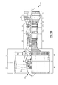
- Figure 1A illustrates a general partial fragmentary schematic view of a gas turbine engine 10 suspended from an engine pylon 12 within an engine nacelle assembly N as is typical of an aircraft designed for subsonic operation.
- the engine 10 includes a core engine within a core nacelle C that houses a low spool 14 and high spool 24.
- the low spool 14 includes a low pressure compressor 16 and low pressure turbine 18.
- the low spool 14 drives a fan section 20 connected to the low spool 14 either directly or through a gear train 25.
- the high spool 24 includes a high pressure compressor 26 and high pressure turbine 28.
- a combustor 30 is arranged between the high pressure compressor 26 and high pressure turbine 28.
- the low and high spools 14, 24 rotate about an engine axis of rotation A.
- the engine 10 in one non-limiting embodiment is a high-bypass geared architecture aircraft engine.
- the engine 10 bypass ratio is greater than about six (6) to ten (10)
- the gear train 22 is an epicyclic gear train such as a planetary gear system or other gear system with a gear reduction ratio of greater than about 2.3
- the low pressure turbine 18 has a pressure ratio that is greater than about 5.
- the bypass ratio is greater than ten (10:1)
- the fan diameter is significantly larger than that of the low pressure compressor 16.
- the gear train 25 may be an epicycle gear train such as a planetary gear system or other gear system with a gear reduction ratio approximately 2.5:1. It should be understood, however, that the above parameters are only exemplary of one embodiment of a geared architecture engine and that the present invention is applicable to other gas turbine engines including direct drive turbofans.
- the fan section 20 communicates airflow into the core nacelle C to the low pressure compressor 16.
- Core airflow compressed by the low pressure compressor 16 and the high pressure compressor 26 is mixed with the fuel in the combustor 30 where it is ignited, and burned.
- the resultant high pressure combustor products are expanded through the high pressure turbine 28 and low pressure turbine 18.
- the turbines 28, 18 are rotationally coupled to the compressors 26, 16 respectively to drive the compressors 26, 16 in response to the expansion of the combustor product.
- the low pressure turbine 18 also drives the fan section 20 through gear train 25.
- the engine static structure 44 generally has substructures including a case structure often referred to as the engine backbone.
- the engine static structure 44 generally includes a fan case 46, an intermediate case (IMC) 48, a high pressure compressor case 50, a combustor case 52A, a high pressure turbine case 52B, a thrust case 52C, a low pressure turbine case 54, and a turbine exhaust case 56 ( Figure 1B ).
- the combustor case 52A, the high pressure turbine case 52B and the thrust case 52C may be combined into a single case. It should be understood that this is an exemplary configuration and any number of cases, and case arrangements may be utilized.
- the fan section 20 includes a fan rotor 32 with a plurality of circumferentially spaced radially outwardly extending fan blades 34.
- the fan blades 34 are surrounded by the fan case 46.
- the core engine case structure is secured to the fan case 46 at the IMC 48 which includes a multiple of circumferentially spaced radially extending struts 40 which radially span the core engine case structure and the fan section 20.
- the multiple of circumferentially spaced radially extending struts 40 are often generically referred to as Fan Exit Guide Vanes (FEGVs).
- the engine static structure 44 further supports a bearing system upon which the turbines 28, 18, compressors 26, 16 and fan rotor 32 rotate.
- a #1 fan dual bearing 60 which rotationally supports the fan rotor 32 is axially located generally within the fan case 46.
- the #1 fan dual bearing 60 is preloaded to react fan thrust forward and aft (in case of surge).
- a #2 LPC bearing 62 which rotationally supports the low spool 14 is axially located generally within the intermediate case (IMC) 48.
- the #2 LPC bearing 62 reacts thrust.
- a #3 HPC bearing 64 which rotationally supports the high spool 24 and also reacts thrust.
- the #3 HPC bearing 64 is also axially located generally within the IMC 48 just forward of the high pressure compressor case 50.
- a #4 bearing 66 which rotationally supports a rear segment of the low spool 14 reacts only radial loads.
- the #4 bearing 66 is axially located generally within the thrust case 52C in an aft section thereof.
- a #5 bearing 68 rotationally supports the rear segment of the low spool 14 and reacts only radial loads.
- the #5 bearing 68 is axially located generally within the thrust case 52C just aft of the #4 bearing 66. It should be understood that this is an exemplary configuration and any number of bearings may be utilized.
- the #4 bearing 66 and the #5 bearing 68 are supported within a mid-turbine frame (MTF) 70 to straddle radially extending structural struts 72 which are preloaded in tension.
- the MTF 70 provides aft structural support within the thrust case 52C for the #4 bearing 66 and the #5 bearing 68 which rotatably support the spools 14, 24.
- a dual rotor engine such as that disclosed in the illustrated embodiment typically includes a forward frame and a rear frame that support the main rotor bearings.
- the intermediate case (IMC) 48 also includes the radially extending struts 40 which are generally radially aligned with the #2 LPC bearing 62. It should be understood that various engines with various case and frame structures will benefit from the present invention.
- the turbofan gas turbine engine 10 is mounted to aircraft structure such as an aircraft wing through a mount system 80 attachable by the pylon 12.
- the mount system 80 includes a forward mount 82 and an aft mount 84.
- the forward mount 82 is secured to the IMC 48 and the aft mount 84 is secured to the MTF 70 at the thrust case 52C.
- the forward mount 82 and the aft mount 84 are arranged in a plane containing the axis A of the engine 10.
- an accessory gearbox 90 may be mounted to the intermediate case (IMC) 48. That is the accessory gearbox 90 may be mounted to the intermediate case (IMC) 48 or be formed integral therewith. It should be understood that the accessory gearbox 90 may be mounted anywhere on the engine static structure 44. In one non-limiting embodiment the accessory gearbox 90 is located axially between the low pressure compressor 16 and the high pressure compressor 26.
- the accessory gearbox 90 provides significant radial area within the core nacelle (C) inboard of the struts 40 to support accessory engine components such as, for example only, a starter/generator (SG), a hydraulic pump (HP), an oil pump (OP), an integrated oil tank (OT), a fuel pump (FP) and others which thereby saves weight and space within the core nacelle (C).
- accessory engine components such as, for example only, a starter/generator (SG), a hydraulic pump (HP), an oil pump (OP), an integrated oil tank (OT), a fuel pump (FP) and others which thereby saves weight and space within the core nacelle (C).
- SG starter/generator
- HP hydraulic pump
- OP oil pump
- OT integrated oil tank
- FP fuel pump
- the engine static structure 44 includes a variable compressor vane system 91 which may include a multiple of low pressure compressor variable vane sets 92A, 92B, 92C and a multiple of high pressure compressor variable vane sets 96A, 96B, 96C, 96D.
- the engine static structure 44 may also include a bleed valve system such as a 2.5 bleed valve actuator system 94.
- the intermediate case (IMC) 48 supports the multiple of low pressure compressor variable vane sets 92A, 92B, 92C.
- the intermediate case (IMC) 48 may also support the 2.5 bleed valve actuator system 94. It should be understood that the 2.5 bleed valve actuator system 94 is located generally between the 2 nd and 3 rd stage, but other bleed valve actuator systems may alternatively or additionally benefit herefrom.
- the high pressure compressor case 50 supports the multiple of high pressure compressor variable vane sets 96A, 96B, 96C. It should be understood that any number of compressor variable vane sets may alternatively or additionally be provided.
- an actuator module 98 is mounted between lobes of the accessory gearbox 90 in one non-limiting embodiment.
- the actuator module 98 generally includes a common actuator housing 100 having a multiple of actuators 102, 104, 106 contained therein.
- Each actuator 102, 104, 106 such as a hydraulic, pneumatic, or electric actuator, for example, drives the respective low pressure compressor variable vane sets 92A, 92B, 92C; 2.5 bleed valve actuator system 94; and the high pressure compressor variable vane sets 96A, 96B, 96C, 96D.
- Each actuator 102, 104, 106 may be connected to various linkages and be actuated independently as required through a control.
- the actuator 102 drives a linkage system 108 such as a bell crank mechanism to operate the low pressure compressor variable vane sets 92A, 92B, 92C.
- the actuator 104 drives a linkage system 110 such as an actuator ring to operate the 2.5 bleed valve actuator system 94.
- the actuator 106 drives a linkage system 112 such as a bell crank mechanism to operate the high pressure compressor variable vane sets 96A, 96B, 96C, 96D. It should be understood that any multiple of actuators may be contained within the actuator module 98 to operate various additional or alternative engine systems.
- an actuator module 98' is mounted directly to the intermediate case (IMC) 48 in another non-limiting embodiment.
- the actuator module 98' is located axially between the low pressure compressor 16 and the high pressure compressor 26.
- the actuator module 98' is also radially located in an annulus defined between the multiple of circumferentially spaced radially extending struts 40 and a multiple of struts 116 within an inner frame 118 of the intermediate case (IMC) 48.
- the inner frame 118 may provide a forward structural support for the #2 LPC bearing 62 which rotatably support the spools 14, 24 within the intermediate case (IMC) 48 which also includes the radially extending struts 40.
- Each actuator may be serviced independently by removing the individual actuator parts from the housing or by removing and replacing the actuator module as a unit.
Landscapes
- Engineering & Computer Science (AREA)
- Mechanical Engineering (AREA)
- General Engineering & Computer Science (AREA)
- Life Sciences & Earth Sciences (AREA)
- Sustainable Development (AREA)
- Structures Of Non-Positive Displacement Pumps (AREA)
- Control Of Turbines (AREA)
Abstract
Description
- The present invention relates to a gas turbine engine integrated actuator module.
- Gas turbine engine performance is typically enhanced through a variable compressor vane system to effectively utilize engine power capacity and enhance transitional performance. The variable compressor vane system typically includes a low pressure compressor variable vane set and a high pressure variable compressor vane set. Each variable vane in each set is rotated in unison through a crank arm linkage. Each crank arm in a set is linked together through a unison ring located circumferentially around the respective compressor case. Each unison ring is rotated by an individual respective actuator to operate the respective variable vane set.
- Although effective, each actuator is individually mounted in various locations about the engine case structure such that each actuator requires a separate individual mount platform and hardware. Relatively significant amounts of space within the engine core nacelle and weight redundancies may thereby be generated.
- An actuator module for a gas turbine engine according to an exemplary aspect of the present disclosure includes an actuator housing, a first actuator mounted within the actuator housing, the first actuator operable to actuate a first variable vane set, and a second actuator mounted within the actuator housing, the second actuator operable to actuate a second variable vane set.
- In a further non-limiting embodiment of the foregoing actuator module embodiment, the actuator module may further comprise a third actuator mounted within the actuator housing, the third actuator operable to actuate a bleed valve system.
- The bleed valve system may comprise a 2.5 bleed valve actuator system.
- In a further non-limiting embodiment of any of the foregoing embodiments, the actuator housing may be mountable to an accessory gearbox. Additionally or alternatively, the actuator housing may be mountable to an engine static structure. Additionally or alternatively, the actuator housing may be mountable to an intermediate case (IMC).
- In a further non-limiting embodiment of any of the foregoing embodiments, the first variable vane set may be a low pressure compressor variable vane set.
- In a further non-limiting embodiment of any of the foregoing embodiments, the second variable vane set may be a high pressure compressor variable vane set.
- A gas turbine engine according to another exemplary aspect of the present disclosure includes a static structure, a core engine, a gear system supported by the static structure, a fan section driven by the core engine through the gear system, an actuator housing mounted to the static structure, and a first actuator mounted within the actuator housing, the first actuator operable to actuate a first variable vane set of the core engine.
- In a further non-limiting embodiment of the foregoing gas turbine engine embodiment, the first variable vane set may be a low pressure compressor variable vane set.
- In a further non-limiting embodiment of any of the foregoing gas turbine engine embodiments, the gas turbine engine may further comprise a second actuator mounted within the actuator housing, the second actuator may be operable to actuate at least one second variable vane set.
- The second variable vane set may be a high pressure compressor variable vane set.
- In a further non-limiting embodiment of any of the foregoing gas turbine engine embodiments, the gear system may define a gear reduction ratio of greater than or equal to about 2.3.
- In a further non-limiting embodiment of any of the foregoing gas turbine engine embodiments, the gear system may define a gear reduction ratio of greater than or equal to about 2.5.
- In a further non-limiting embodiment of any of the foregoing gas turbine engine embodiments, the gear system may define a gear reduction ratio of greater than or equal to 2.5.
- In a further non-limiting embodiment of any of the foregoing gas turbine engine embodiments, the core engine may include a low pressure turbine which defines a pressure ratio that is greater than about five (5).
- In a further non-limiting embodiment of any of the foregoing gas turbine engine embodiments, the core engine may include a low pressure turbine which defines a pressure ratio that is greater than five (5).
- In a further non-limiting embodiment of any of the foregoing gas turbine engine embodiments, the fan section may be mounted within a fan nacelle and the core engine may be mounted within a core nacelle, the fan nacelle may be mounted at least partially around the core nacelle to define a fan bypass flow path for a fan bypass airflow, the fan bypass airflow may define a bypass ratio greater than about six (6).
- In a non-limiting embodiment the bypass airflow may define a bypass ratio greater than about ten (10).
- In a non-limiting embodiment the bypass flow may define a bypass ratio greater than ten (10).
- The various features and advantages of this invention will become apparent to those skilled in the art from the following detailed description of the disclosed non-limiting embodiment. The drawings that accompany the detailed description can be briefly described as follows:
-
Figure 1A is a general schematic sectional view through a gas turbine engine along the engine longitudinal axis; -
Figure 1B is a general sectional view through a gas turbine engine along the engine longitudinal axis illustrating an engine static structure case arrangement on the lower half thereof; -
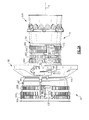
Figure 2A is a side partial sectional view of a gas turbine engine illustrating an engine static structure case arrangement with an accessory gearbox mounted thereto; -
Figure 2B is a perspective view of a gas turbine engine looking forward to illustrate the piggy-back of accessory components onto the accessory gearbox; -
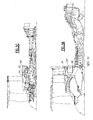
Figure 2C is a general sectional view through the gas turbine engine along the engine longitudinal axis illustrating the accessory gearbox and actuator module location; -
Figure 2D is a partial sectional view through a nacelle structure of a gas turbine engine illustrating the accessory gearbox and actuator module location; -
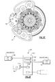
Figure 2E is a rear view of an engine static structure case arrangement illustrating the actuator module location between lobes of the accessory gearbox; -
Figure 2F is a schematic view of the actuator module; -
Figure 3A is a general sectional view through the gas turbine engine along the engine longitudinal axis illustrating another actuator module location for a gas turbine engine without an accessory gearbox; and -
Figure 3B is a perspective view of the intermediate case (IMC) of the gas turbine engine ofFigure 3A illustrating the actuator module location mounted directly to the IMC. - In the foregoing paragraphs, each paragraph begins with the respective figures being identified which are about to be explained. If no figures are called out at the beginning of the paragraph, it should be inferred that the same figures are to be referenced as in the preceding paragraph(s).
-
Figure 1A illustrates a general partial fragmentary schematic view of agas turbine engine 10 suspended from anengine pylon 12 within an engine nacelle assembly N as is typical of an aircraft designed for subsonic operation. - The
engine 10 includes a core engine within a core nacelle C that houses alow spool 14 andhigh spool 24. Thelow spool 14 includes alow pressure compressor 16 andlow pressure turbine 18. Thelow spool 14 drives afan section 20 connected to thelow spool 14 either directly or through agear train 25. - The
high spool 24 includes ahigh pressure compressor 26 andhigh pressure turbine 28. Acombustor 30 is arranged between thehigh pressure compressor 26 andhigh pressure turbine 28. The low andhigh spools - The
engine 10 in one non-limiting embodiment is a high-bypass geared architecture aircraft engine. In one disclosed, non-limiting embodiment, theengine 10 bypass ratio is greater than about six (6) to ten (10), the gear train 22 is an epicyclic gear train such as a planetary gear system or other gear system with a gear reduction ratio of greater than about 2.3 and thelow pressure turbine 18 has a pressure ratio that is greater than about 5. In one disclosed embodiment, the bypass ratio is greater than ten (10:1), the fan diameter is significantly larger than that of thelow pressure compressor 16. Thegear train 25 may be an epicycle gear train such as a planetary gear system or other gear system with a gear reduction ratio approximately 2.5:1. It should be understood, however, that the above parameters are only exemplary of one embodiment of a geared architecture engine and that the present invention is applicable to other gas turbine engines including direct drive turbofans. - Airflow enters the fan nacelle F which at least partially surrounds the core nacelle C. The
fan section 20 communicates airflow into the core nacelle C to thelow pressure compressor 16. Core airflow compressed by thelow pressure compressor 16 and thehigh pressure compressor 26 is mixed with the fuel in thecombustor 30 where it is ignited, and burned. The resultant high pressure combustor products are expanded through thehigh pressure turbine 28 andlow pressure turbine 18. Theturbines compressors compressors low pressure turbine 18 also drives thefan section 20 throughgear train 25. A core engine exhaust exits the core nacelle C through acore nozzle 43 defined between the core nacelle C and atail cone 33. - Referring to
Figure 1B , the enginestatic structure 44 generally has substructures including a case structure often referred to as the engine backbone. The enginestatic structure 44 generally includes afan case 46, an intermediate case (IMC) 48, a highpressure compressor case 50, acombustor case 52A, a highpressure turbine case 52B, athrust case 52C, a lowpressure turbine case 54, and a turbine exhaust case 56 (Figure 1B ). Alternatively, thecombustor case 52A, the highpressure turbine case 52B and thethrust case 52C may be combined into a single case. It should be understood that this is an exemplary configuration and any number of cases, and case arrangements may be utilized. - The
fan section 20 includes afan rotor 32 with a plurality of circumferentially spaced radially outwardly extendingfan blades 34. Thefan blades 34 are surrounded by thefan case 46. The core engine case structure is secured to thefan case 46 at theIMC 48 which includes a multiple of circumferentially spaced radially extendingstruts 40 which radially span the core engine case structure and thefan section 20. The multiple of circumferentially spaced radially extendingstruts 40 are often generically referred to as Fan Exit Guide Vanes (FEGVs). - Referring to
Figure 1A and1B , the enginestatic structure 44 further supports a bearing system upon which theturbines compressors fan rotor 32 rotate. A #1 fandual bearing 60 which rotationally supports thefan rotor 32 is axially located generally within thefan case 46. The #1 fandual bearing 60 is preloaded to react fan thrust forward and aft (in case of surge). A #2 LPC bearing 62 which rotationally supports thelow spool 14 is axially located generally within the intermediate case (IMC) 48. The #2LPC bearing 62 reacts thrust. A #3 HPC bearing 64 which rotationally supports thehigh spool 24 and also reacts thrust. The #3HPC bearing 64 is also axially located generally within theIMC 48 just forward of the highpressure compressor case 50. A #4bearing 66 which rotationally supports a rear segment of thelow spool 14 reacts only radial loads. The #4bearing 66 is axially located generally within thethrust case 52C in an aft section thereof. A #5bearing 68 rotationally supports the rear segment of thelow spool 14 and reacts only radial loads. The #5bearing 68 is axially located generally within thethrust case 52C just aft of the #4bearing 66. It should be understood that this is an exemplary configuration and any number of bearings may be utilized. - The #4
bearing 66 and the #5bearing 68 are supported within a mid-turbine frame (MTF) 70 to straddle radially extendingstructural struts 72 which are preloaded in tension. TheMTF 70 provides aft structural support within thethrust case 52C for the #4bearing 66 and the #5bearing 68 which rotatably support thespools - A dual rotor engine such as that disclosed in the illustrated embodiment typically includes a forward frame and a rear frame that support the main rotor bearings. The intermediate case (IMC) 48 also includes the
radially extending struts 40 which are generally radially aligned with the #2LPC bearing 62. It should be understood that various engines with various case and frame structures will benefit from the present invention. - The turbofan
gas turbine engine 10 is mounted to aircraft structure such as an aircraft wing through amount system 80 attachable by thepylon 12. Themount system 80 includes aforward mount 82 and anaft mount 84. Theforward mount 82 is secured to theIMC 48 and theaft mount 84 is secured to theMTF 70 at thethrust case 52C. Theforward mount 82 and theaft mount 84 are arranged in a plane containing the axis A of theengine 10. - Referring to
Figure 1B and2A , anaccessory gearbox 90 may be mounted to the intermediate case (IMC) 48. That is theaccessory gearbox 90 may be mounted to the intermediate case (IMC) 48 or be formed integral therewith. It should be understood that theaccessory gearbox 90 may be mounted anywhere on the enginestatic structure 44. In one non-limiting embodiment theaccessory gearbox 90 is located axially between thelow pressure compressor 16 and thehigh pressure compressor 26. - Referring to
Figure 2B and2C , theaccessory gearbox 90 provides significant radial area within the core nacelle (C) inboard of thestruts 40 to support accessory engine components such as, for example only, a starter/generator (SG), a hydraulic pump (HP), an oil pump (OP), an integrated oil tank (OT), a fuel pump (FP) and others which thereby saves weight and space within the core nacelle (C). It should be understood, that any number and type of accessory components are readily mountable on or adjacent to theaccessory gearbox 90. - Referring to
Figure 1B and2F , the enginestatic structure 44 includes a variablecompressor vane system 91 which may include a multiple of low pressure compressor variable vane sets 92A, 92B, 92C and a multiple of high pressure compressor variable vane sets 96A, 96B, 96C, 96D. The enginestatic structure 44 may also include a bleed valve system such as a 2.5 bleedvalve actuator system 94. - The intermediate case (IMC) 48 supports the multiple of low pressure compressor variable vane sets 92A, 92B, 92C. The intermediate case (IMC) 48 may also support the 2.5 bleed
valve actuator system 94. It should be understood that the 2.5 bleedvalve actuator system 94 is located generally between the 2nd and 3rd stage, but other bleed valve actuator systems may alternatively or additionally benefit herefrom. The highpressure compressor case 50 supports the multiple of high pressure compressor variable vane sets 96A, 96B, 96C. It should be understood that any number of compressor variable vane sets may alternatively or additionally be provided. - Referring to
Figures 2D ,2E, and 2F , anactuator module 98 is mounted between lobes of theaccessory gearbox 90 in one non-limiting embodiment. Theactuator module 98 generally includes acommon actuator housing 100 having a multiple ofactuators actuator valve actuator system 94; and the high pressure compressor variable vane sets 96A, 96B, 96C, 96D. - Each
actuator actuator 102 drives alinkage system 108 such as a bell crank mechanism to operate the low pressure compressor variable vane sets 92A, 92B, 92C. Theactuator 104 drives alinkage system 110 such as an actuator ring to operate the 2.5 bleedvalve actuator system 94. Theactuator 106 drives alinkage system 112 such as a bell crank mechanism to operate the high pressure compressor variable vane sets 96A, 96B, 96C, 96D. It should be understood that any multiple of actuators may be contained within theactuator module 98 to operate various additional or alternative engine systems. - Referring to
Figure 1B ,3A , and3B , anactuator module 98' is mounted directly to the intermediate case (IMC) 48 in another non-limiting embodiment. Theactuator module 98' is located axially between thelow pressure compressor 16 and thehigh pressure compressor 26. Theactuator module 98' is also radially located in an annulus defined between the multiple of circumferentially spaced radially extendingstruts 40 and a multiple ofstruts 116 within aninner frame 118 of the intermediate case (IMC) 48. Theinner frame 118 may provide a forward structural support for the #2 LPC bearing 62 which rotatably support thespools radially extending struts 40. It should be understood that various engines with various case and frame structures will benefit herefrom. - Integration of the compressor actuators within the actuator module reduces actuator space; eliminates redundant mounting material and parts; and reduces maintenance schedule time and complexity. Each actuator may be serviced independently by removing the individual actuator parts from the housing or by removing and replacing the actuator module as a unit.
- It should be understood that relative positional terms such as "forward," "aft," "upper," "lower," "above," "below," and the like are with reference to the normal operational attitude of the vehicle and should not be considered otherwise limiting.
- It should be understood that although a particular component arrangement is disclosed in the illustrated embodiment, other arrangements will benefit from the instant invention.
- The foregoing description is exemplary rather than defined by the limitations within. Many modifications and variations are possible in light of the above teachings. Non-limiting embodiments are disclosed herein, however, one of ordinary skill in the art would recognize that certain modifications would come within the scope of this invention. It is, therefore, to be understood that within the scope of the appended claims, the invention may be practiced otherwise than as specifically described. For that reason the following claims should be studied to determine the true scope and content of this invention.
Claims (15)
- An actuator module (98;98') for a gas turbine engine comprising:an actuator housing (100);a first actuator (102) mounted within said actuator housing (100), said first actuator (102) operable to actuate a first variable vane set (92A;92B;92C); anda second actuator (106) mounted within said actuator housing (100), said second actuator (106) operable to actuate a second variable vane set (96A;96B;96C;96D).
- The actuator module as recited in claim 1, further comprising a third actuator (104) mounted within said actuator housing (100), said third actuator (104) operable to actuate a bleed valve system (94), for example a 2.5 bleed valve actuator system.
- The actuator module as recited in claim 1 or 2, wherein said actuator housing (100) is mountable to an accessory gearbox (90).
- The actuator module as recited in any preceding claim, wherein said actuator housing (100) is mountable to an engine static structure.
- The actuator module as recited in any preceding claim, wherein said actuator housing (100) is mountable to an intermediate case (IMC) (48).
- The actuator module as recited in any preceding claim, wherein said first variable vane set (92A,92B,92C) is a low pressure compressor variable vane set.
- The actuator module as recited in any preceding claim, wherein said second variable vane set (96A,96B,96C;96D) is a high pressure compressor variable vane set.
- A gas turbine engine comprising the actuator module of any preceding claim.
- A gas turbine engine (10) comprising:a static structure;a core engine;a gear system (25) supported by said static structure;a fan section (20) driven by said core engine through said gear system (25);an actuator housing (100) mounted to said static structure; anda first actuator (102) mounted within said actuator housing (100), said first actuator (102) operable to actuate a first variable vane set (92A;92B;92C) of said core engine.
- The engine as recited in claim 9, wherein said first variable vane set (92A;92B;92C) is a low pressure compressor variable vane set.
- The engine as recited in claim 9 or 10, further comprising a second actuator (106) mounted within said actuator housing (100), said second actuator (106) operable to actuate at least one second variable vane set (96A;96B;96C;96D).
- The engine as recited in claim 11, wherein said second variable vane set (96A;96B;96C;96D) is a high pressure compressor variable vane set.
- The engine as recited in any of claims 9 to 12, wherein said gear system (25) defines a gear reduction ratio of greater than or equal to about 2.3, for example a gear reduction ratio of greater than or equal to about 2.5, for example a gear reduction ratio of greater than or equal to 2.5.
- The engine as recited in any of claims 9 to 13, wherein said core engine includes a low pressure turbine (18) which defines a pressure ratio that is greater than about five (5) or is greater than five (5).
- The engine as recited in any of claims 9 to 14, wherein said fan section (20) is mounted within a fan nacelle (F) and said core engine is mounted within a core nacelle (C), said fan nacelle (F) mounted at least partially around said core nacelle (C) to define a fan bypass flow path for a fan bypass airflow, said fan bypass airflow defines a bypass ratio greater than about six (6), for example a bypass ratio greater than about ten (10), for example a bypass ratio greater than ten (10).
Applications Claiming Priority (1)
| Application Number | Priority Date | Filing Date | Title |
|---|---|---|---|
| US13/327,722 US9097137B2 (en) | 2008-06-12 | 2011-12-15 | Integrated actuator module for gas turbine engine |
Publications (2)
| Publication Number | Publication Date |
|---|---|
| EP2604810A2 true EP2604810A2 (en) | 2013-06-19 |
| EP2604810A3 EP2604810A3 (en) | 2013-09-18 |
Family
ID=47504679
Family Applications (1)
| Application Number | Title | Priority Date | Filing Date |
|---|---|---|---|
| EP12196780.6A Withdrawn EP2604810A3 (en) | 2011-12-15 | 2012-12-12 | Integrated Actuator Module for Gas Turbine Engine |
Country Status (1)
| Country | Link |
|---|---|
| EP (1) | EP2604810A3 (en) |
Cited By (1)
| Publication number | Priority date | Publication date | Assignee | Title |
|---|---|---|---|---|
| CN104747293A (en) * | 2013-12-27 | 2015-07-01 | 中航商用航空发动机有限责任公司 | A type selecting method of a starter used for a turbofan engine |
Citations (1)
| Publication number | Priority date | Publication date | Assignee | Title |
|---|---|---|---|---|
| EP2098704A2 (en) * | 2008-03-05 | 2009-09-09 | United Technologies Corporation | Variable area fan nozzle fan flutter management system |
Family Cites Families (1)
| Publication number | Priority date | Publication date | Assignee | Title |
|---|---|---|---|---|
| US8210800B2 (en) * | 2008-06-12 | 2012-07-03 | United Technologies Corporation | Integrated actuator module for gas turbine engine |
-
2012
- 2012-12-12 EP EP12196780.6A patent/EP2604810A3/en not_active Withdrawn
Patent Citations (1)
| Publication number | Priority date | Publication date | Assignee | Title |
|---|---|---|---|---|
| EP2098704A2 (en) * | 2008-03-05 | 2009-09-09 | United Technologies Corporation | Variable area fan nozzle fan flutter management system |
Cited By (2)
| Publication number | Priority date | Publication date | Assignee | Title |
|---|---|---|---|---|
| CN104747293A (en) * | 2013-12-27 | 2015-07-01 | 中航商用航空发动机有限责任公司 | A type selecting method of a starter used for a turbofan engine |
| CN104747293B (en) * | 2013-12-27 | 2017-04-19 | 中航商用航空发动机有限责任公司 | A type selecting method of a starter used for a turbofan engine |
Also Published As
| Publication number | Publication date |
|---|---|
| EP2604810A3 (en) | 2013-09-18 |
Similar Documents
| Publication | Publication Date | Title |
|---|---|---|
| EP2133514B1 (en) | Integrated actuator module for gas turbine engine | |
| US9097137B2 (en) | Integrated actuator module for gas turbine engine | |
| EP2390486B1 (en) | Accessory gearbox with internal layshaft | |
| EP2065585B1 (en) | Gas turbine engine with pylon mounted accessory drive | |
| CA2849013C (en) | Gas turbine engine with low stage count low pressure turbine | |
| EP2060759B1 (en) | Gas turbine with two accessory drive gearboxes | |
| US8490411B2 (en) | Axial accessory gearbox | |
| US20100242496A1 (en) | Gas turbine engine with stacked accessory components | |
| US20130125561A1 (en) | Geared turbofan with distributed accessory gearboxes | |
| CA2800001C (en) | Gas turbine engine compressor arrangement | |
| US20090205341A1 (en) | Gas turbine engine with twin towershaft accessory gearbox | |
| US20160097304A1 (en) | Gas turbine engine with low stage count low pressure turbine | |
| EP2809889B1 (en) | Turbomachine geared architecture support assembly | |
| US20120117940A1 (en) | Gas turbine engine with pylon mounted accessory drive | |
| EP2904239B1 (en) | Assembly comprising a geared turbofan, a pylon and a wing | |
| EP2904234B1 (en) | Geared turbine engine with relatively lightweight propulsor module | |
| CA2802060A1 (en) | Gas turbine engine with pylon mounted accessory drive | |
| WO2014052967A1 (en) | Case assembly for a gas turbine engine | |
| EP2604810A2 (en) | Integrated Actuator Module for Gas Turbine Engine | |
| EP2610462B1 (en) | Gas turbine engine | |
| WO2013165771A1 (en) | Geared turbofan with distributed accessory gearboxes |
Legal Events
| Date | Code | Title | Description |
|---|---|---|---|
| PUAI | Public reference made under article 153(3) epc to a published international application that has entered the european phase |
Free format text: ORIGINAL CODE: 0009012 |
|
| AK | Designated contracting states |
Kind code of ref document: A2 Designated state(s): AL AT BE BG CH CY CZ DE DK EE ES FI FR GB GR HR HU IE IS IT LI LT LU LV MC MK MT NL NO PL PT RO RS SE SI SK SM TR |
|
| AX | Request for extension of the european patent |
Extension state: BA ME |
|
| PUAL | Search report despatched |
Free format text: ORIGINAL CODE: 0009013 |
|
| AK | Designated contracting states |
Kind code of ref document: A3 Designated state(s): AL AT BE BG CH CY CZ DE DK EE ES FI FR GB GR HR HU IE IS IT LI LT LU LV MC MK MT NL NO PL PT RO RS SE SI SK SM TR |
|
| AX | Request for extension of the european patent |
Extension state: BA ME |
|
| RIC1 | Information provided on ipc code assigned before grant |
Ipc: F04D 29/56 20060101ALI20130814BHEP Ipc: F01D 17/16 20060101AFI20130814BHEP |
|
| 17P | Request for examination filed |
Effective date: 20140313 |
|
| RBV | Designated contracting states (corrected) |
Designated state(s): AL AT BE BG CH CY CZ DE DK EE ES FI FR GB GR HR HU IE IS IT LI LT LU LV MC MK MT NL NO PL PT RO RS SE SI SK SM TR |
|
| RAP1 | Party data changed (applicant data changed or rights of an application transferred) |
Owner name: UNITED TECHNOLOGIES CORPORATION |
|
| STAA | Information on the status of an ep patent application or granted ep patent |
Free format text: STATUS: EXAMINATION IS IN PROGRESS |
|
| 17Q | First examination report despatched |
Effective date: 20161201 |
|
| STAA | Information on the status of an ep patent application or granted ep patent |
Free format text: STATUS: THE APPLICATION IS DEEMED TO BE WITHDRAWN |
|
| 18D | Application deemed to be withdrawn |
Effective date: 20190731 |