EP2604804A2 - Fan blade tip clearance control - Google Patents
Fan blade tip clearance control Download PDFInfo
- Publication number
- EP2604804A2 EP2604804A2 EP12196594.1A EP12196594A EP2604804A2 EP 2604804 A2 EP2604804 A2 EP 2604804A2 EP 12196594 A EP12196594 A EP 12196594A EP 2604804 A2 EP2604804 A2 EP 2604804A2
- Authority
- EP
- European Patent Office
- Prior art keywords
- seal ring
- casing
- engine
- band
- bands
- Prior art date
- Legal status (The legal status is an assumption and is not a legal conclusion. Google has not performed a legal analysis and makes no representation as to the accuracy of the status listed.)
- Granted
Links
- 239000000463 material Substances 0.000 claims description 31
- 229910052782 aluminium Inorganic materials 0.000 claims description 17
- XAGFODPZIPBFFR-UHFFFAOYSA-N aluminium Chemical compound [Al] XAGFODPZIPBFFR-UHFFFAOYSA-N 0.000 claims description 17
- 239000002131 composite material Substances 0.000 claims description 10
- 238000000034 method Methods 0.000 claims description 6
- PXHVJJICTQNCMI-UHFFFAOYSA-N Nickel Chemical compound [Ni] PXHVJJICTQNCMI-UHFFFAOYSA-N 0.000 claims description 4
- 239000007787 solid Substances 0.000 claims description 4
- 229910000838 Al alloy Inorganic materials 0.000 claims description 3
- 229910000990 Ni alloy Inorganic materials 0.000 claims description 3
- 229910000831 Steel Inorganic materials 0.000 claims description 3
- 239000010959 steel Substances 0.000 claims description 3
- RTAQQCXQSZGOHL-UHFFFAOYSA-N Titanium Chemical compound [Ti] RTAQQCXQSZGOHL-UHFFFAOYSA-N 0.000 claims description 2
- 239000011159 matrix material Substances 0.000 claims description 2
- 229910052759 nickel Inorganic materials 0.000 claims description 2
- 239000010936 titanium Substances 0.000 claims description 2
- 229910052719 titanium Inorganic materials 0.000 claims description 2
- 239000000956 alloy Substances 0.000 claims 1
- 239000007769 metal material Substances 0.000 description 2
- 238000012986 modification Methods 0.000 description 2
- 230000004048 modification Effects 0.000 description 2
- 239000003570 air Substances 0.000 description 1
- 239000012080 ambient air Substances 0.000 description 1
- 239000000835 fiber Substances 0.000 description 1
- 239000012530 fluid Substances 0.000 description 1
- 238000010438 heat treatment Methods 0.000 description 1
- NPURPEXKKDAKIH-UHFFFAOYSA-N iodoimino(oxo)methane Chemical compound IN=C=O NPURPEXKKDAKIH-UHFFFAOYSA-N 0.000 description 1
- 229910052751 metal Inorganic materials 0.000 description 1
Images
Classifications
-
- F—MECHANICAL ENGINEERING; LIGHTING; HEATING; WEAPONS; BLASTING
- F01—MACHINES OR ENGINES IN GENERAL; ENGINE PLANTS IN GENERAL; STEAM ENGINES
- F01D—NON-POSITIVE DISPLACEMENT MACHINES OR ENGINES, e.g. STEAM TURBINES
- F01D11/00—Preventing or minimising internal leakage of working-fluid, e.g. between stages
- F01D11/08—Preventing or minimising internal leakage of working-fluid, e.g. between stages for sealing space between rotor blade tips and stator
-
- F—MECHANICAL ENGINEERING; LIGHTING; HEATING; WEAPONS; BLASTING
- F01—MACHINES OR ENGINES IN GENERAL; ENGINE PLANTS IN GENERAL; STEAM ENGINES
- F01D—NON-POSITIVE DISPLACEMENT MACHINES OR ENGINES, e.g. STEAM TURBINES
- F01D11/00—Preventing or minimising internal leakage of working-fluid, e.g. between stages
- F01D11/005—Sealing means between non relatively rotating elements
-
- F—MECHANICAL ENGINEERING; LIGHTING; HEATING; WEAPONS; BLASTING
- F01—MACHINES OR ENGINES IN GENERAL; ENGINE PLANTS IN GENERAL; STEAM ENGINES
- F01D—NON-POSITIVE DISPLACEMENT MACHINES OR ENGINES, e.g. STEAM TURBINES
- F01D11/00—Preventing or minimising internal leakage of working-fluid, e.g. between stages
- F01D11/08—Preventing or minimising internal leakage of working-fluid, e.g. between stages for sealing space between rotor blade tips and stator
- F01D11/14—Adjusting or regulating tip-clearance, i.e. distance between rotor-blade tips and stator casing
- F01D11/16—Adjusting or regulating tip-clearance, i.e. distance between rotor-blade tips and stator casing by self-adjusting means
- F01D11/18—Adjusting or regulating tip-clearance, i.e. distance between rotor-blade tips and stator casing by self-adjusting means using stator or rotor components with predetermined thermal response, e.g. selective insulation, thermal inertia, differential expansion
Definitions
- the present disclosure relates to a blade tip clearance control system, more specifically a fan blade tip clearance control system, to be used in engines such as gas turbine engines.
- fan blades may be formed from an aluminum material, while the casing surrounding the fan blades may be formed from a composite material. There can be large differences in the thermal growth of these two materials. As a result, blade tip clearances may go beyond a desired range and fan efficiency may decrease.
- a system which helps maintain control of the blade tip clearance is highly desirable from the standpoint of obtaining fan efficiency.
- an engine which broadly comprises a blade, a casing surrounding the blade, a seal ring, and a passive system for connecting the seal ring to the casing and for accommodating thermal expansion of the seal ring relative to the casing so as to maintain blade tip clearance control.
- a method for maintaining blade clearance tip control in a fan section of an engine which method broadly comprises the steps of: providing a fan casing formed from a composite material and a plurality of fan blades formed from an aluminum containing material; providing an annular seal ring; and providing a passive system for connecting the seal ring to the casing and for accommodating thermal expansion of the seal ring relative to the casing so as to maintain the blade tip clearance control.
- the gas turbine engine 10 includes a fan section 12, a compressor section 14, a combustor section 16, and a turbine section 18.
- the gas turbine engine 10 has an axially extending centerline 22. Ambient air enters the engine 10 through the fan section 12. A fraction of that air subsequently travels through the compressor, combustor and turbine sections 14, 16, and 18 as core gas flow before exiting through a nozzle.
- the fan section 12 includes a fan casing 30 and a plurality of fan blades 32 which rotate about the centerline 22.
- the fan blades 32 are each connected to a fan rotor disk 34 which may be driven by a spool or shaft 33 connected to a low pressure turbine array 35 in the turbine section 18.
- each fan blade 32 may be formed from an aluminum containing material such as an aluminum or an aluminum alloy where aluminum is present in an amount greater than 50 percent by weight.
- the fan casing 30 may be formed from any suitable material. If desired, the fan casing 30 may be formed from a composite material such as an organic matrix composite material.
- the fan casing 30 is provided with a seal ring 40 such as an abradable seal ring.
- the seal ring 40 may comprise an annular rub strip 42 formed from an abradable material and an annular backing ring 44.
- the backing ring 44 may be formed from a metallic material such as an aluminum containing material including, but not limited to, aluminum and aluminum alloys where aluminum is present in an amount greater than 50 percent by weight. The backing ring 44 thus passively matches the thermal growth of the fan blades 32.
- a passive system 48 for connecting the seal ring 40 to the fan casing 30 is provided.
- the passive system 48 accommodates thermal expansion of the seal ring 40 relative to the fan casing 30 so as to maintain blade tip clearance control.
- the system 48 is passive because it does not require the use of sensors, heating elements, piezoelectric materials, shape memory metal elements, fluid control systems, and the like.
- the passive system 48 may comprise a plurality of Z-bands 50 extending between an inner wall 52 of an annular duct portion 54 of the fan casing 30 and the abradable seal ring 40.
- Each Z-band 50 may be formed from a non-corrugated, solid piece of metallic material such as nickel sheet material, a nickel alloy sheet material such as INCO 718, a steel sheet material, a titanium sheet material, an aluminum sheet material or a composite sheet material.
- the material which is used for each Z-band may have a thermal growth which falls between the thermal growth of the material forming the fan casing and the thermal growth of aluminum.
- Each Z-band 50 may have an annular configuration and extend about the entire inner periphery of the duct portion 54.
- each Z-band 50 may comprise an arc segment which extends about a portion of the inner periphery of the duct portion 54. If metallic, each Z-band may have a thickness in the range of 0.015 to 0.030 inches (0.381 to 0.762 mm). If composite, each Z-band may have a thickness in a wider range of 0.015 to 0.060 inches (0.381 to 1.524 mm) due to fiber orientation and lay-up possibilities.
- Each Z-band 50 may be attached to the inner wall 52 and to the exterior surface 56 of the backing ring 44. Any suitable means may be used to attach each Z-band 50 to the inner wall 52 and to the exterior surface 56. For example, nuts and bolts may be used to join each Z-band 50 to the inner wall 52 and the exterior surface 56.
- the fan casing 30 and the backing ring 44 are formed by different materials having different thermal expansion coefficients.
- the Z-bands 50 allow the backing ring 44 to thermally expand relative to the fan casing 30.
- Each Z-band 50 may be provided with a thickness which is sufficiently thin so that the alpha thermal differences between the Z-bands 50 and the backing ring 44 have minimal influence on the backing ring 44 and hence blade tip clearance is maintained.
- the passive system 48 may comprise multiple Z-bands, for example, three Z-bands 50 with a first of the Z-bands 50 being attached to a leading edge portion 60 of the seal ring 40, a second of the Z-bands 50 being attached to a trailing edge portion 62 of the seal ring 40, and a third of the Z-bands 50 is attached to the seal ring 40 intermediate of the first and second ones of the Z-bands 50.
- the passive system 48 further comprises a slip joint 64 between the fan casing 30 and the abradable seal ring 40.
- the slip joint 64 may be located adjacent the leading edge and trailing edge portions 60 and 62 respectively of the seal ring 40 and a wall 70 of the fan casing 30.
- the passive system 48 allows the seal ring 40 to grow different from the fan casing 30 and move thermally independent of the fan casing 30. As a result, increases in fan efficiencies may be obtained.
Landscapes
- Engineering & Computer Science (AREA)
- Mechanical Engineering (AREA)
- General Engineering & Computer Science (AREA)
- Turbine Rotor Nozzle Sealing (AREA)
- Structures Of Non-Positive Displacement Pumps (AREA)
Abstract
Description
- The present disclosure relates to a blade tip clearance control system, more specifically a fan blade tip clearance control system, to be used in engines such as gas turbine engines.
- In a gas turbine engine, fan blades may be formed from an aluminum material, while the casing surrounding the fan blades may be formed from a composite material. There can be large differences in the thermal growth of these two materials. As a result, blade tip clearances may go beyond a desired range and fan efficiency may decrease.
- A system which helps maintain control of the blade tip clearance is highly desirable from the standpoint of obtaining fan efficiency.
- In accordance with the present disclosure, there is provided an engine which broadly comprises a blade, a casing surrounding the blade, a seal ring, and a passive system for connecting the seal ring to the casing and for accommodating thermal expansion of the seal ring relative to the casing so as to maintain blade tip clearance control.
- Further in accordance with the present disclosure, there is provided a method for maintaining blade clearance tip control in a fan section of an engine, which method broadly comprises the steps of: providing a fan casing formed from a composite material and a plurality of fan blades formed from an aluminum containing material; providing an annular seal ring; and providing a passive system for connecting the seal ring to the casing and for accommodating thermal expansion of the seal ring relative to the casing so as to maintain the blade tip clearance control.
- Other details of the fan blade tip clearance control via Z-bands are set forth in the following detailed description and the accompanying drawings, wherein like reference numerals depict like elements.
-
-
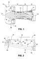
FIG. 1 is a schematic representation of a gas turbine engine having a fan section; and -
FIG. 2 is a sectional view of a system for maintaining blade tip clearance control. - Referring now to
FIG. 1 , agas turbine engine 10 is diagrammatically shown. Thegas turbine engine 10 includes afan section 12, acompressor section 14, acombustor section 16, and aturbine section 18. Thegas turbine engine 10 has an axially extendingcenterline 22. Ambient air enters theengine 10 through thefan section 12. A fraction of that air subsequently travels through the compressor, combustor andturbine sections - The
fan section 12 includes afan casing 30 and a plurality offan blades 32 which rotate about thecenterline 22. Thefan blades 32 are each connected to afan rotor disk 34 which may be driven by a spool orshaft 33 connected to a lowpressure turbine array 35 in theturbine section 18. If desired, eachfan blade 32 may be formed from an aluminum containing material such as an aluminum or an aluminum alloy where aluminum is present in an amount greater than 50 percent by weight. - The
fan casing 30 may be formed from any suitable material. If desired, thefan casing 30 may be formed from a composite material such as an organic matrix composite material. - Referring now to
Fig. 2 , thefan casing 30 is provided with aseal ring 40 such as an abradable seal ring. Theseal ring 40 may comprise anannular rub strip 42 formed from an abradable material and anannular backing ring 44. Thebacking ring 44 may be formed from a metallic material such as an aluminum containing material including, but not limited to, aluminum and aluminum alloys where aluminum is present in an amount greater than 50 percent by weight. Thebacking ring 44 thus passively matches the thermal growth of thefan blades 32. - It is desirable to maintain a clearance distance between the
seal ring 40 and thetip 46 of eachfan blade 32. To this end, apassive system 48 for connecting theseal ring 40 to thefan casing 30 is provided. Thepassive system 48 accommodates thermal expansion of theseal ring 40 relative to thefan casing 30 so as to maintain blade tip clearance control. Thesystem 48 is passive because it does not require the use of sensors, heating elements, piezoelectric materials, shape memory metal elements, fluid control systems, and the like. - The
passive system 48 may comprise a plurality of Z-bands 50 extending between aninner wall 52 of anannular duct portion 54 of thefan casing 30 and theabradable seal ring 40. Each Z-band 50 may be formed from a non-corrugated, solid piece of metallic material such as nickel sheet material, a nickel alloy sheet material such as INCO 718, a steel sheet material, a titanium sheet material, an aluminum sheet material or a composite sheet material. The material which is used for each Z-band may have a thermal growth which falls between the thermal growth of the material forming the fan casing and the thermal growth of aluminum. Each Z-band 50 may have an annular configuration and extend about the entire inner periphery of theduct portion 54. Alternatively, each Z-band 50 may comprise an arc segment which extends about a portion of the inner periphery of theduct portion 54. If metallic, each Z-band may have a thickness in the range of 0.015 to 0.030 inches (0.381 to 0.762 mm). If composite, each Z-band may have a thickness in a wider range of 0.015 to 0.060 inches (0.381 to 1.524 mm) due to fiber orientation and lay-up possibilities. - Each Z-
band 50 may be attached to theinner wall 52 and to theexterior surface 56 of thebacking ring 44. Any suitable means may be used to attach each Z-band 50 to theinner wall 52 and to theexterior surface 56. For example, nuts and bolts may be used to join each Z-band 50 to theinner wall 52 and theexterior surface 56. - As can be seen from the foregoing discussion, the
fan casing 30 and thebacking ring 44 are formed by different materials having different thermal expansion coefficients. - The Z-
bands 50 allow thebacking ring 44 to thermally expand relative to thefan casing 30. Each Z-band 50 may be provided with a thickness which is sufficiently thin so that the alpha thermal differences between the Z-bands 50 and thebacking ring 44 have minimal influence on thebacking ring 44 and hence blade tip clearance is maintained. - If desired, the
passive system 48 may comprise multiple Z-bands, for example, three Z-bands 50 with a first of the Z-bands 50 being attached to a leadingedge portion 60 of theseal ring 40, a second of the Z-bands 50 being attached to atrailing edge portion 62 of theseal ring 40, and a third of the Z-bands 50 is attached to theseal ring 40 intermediate of the first and second ones of the Z-bands 50. - The
passive system 48 further comprises aslip joint 64 between thefan casing 30 and theabradable seal ring 40. Theslip joint 64 may be located adjacent the leading edge andtrailing edge portions seal ring 40 and awall 70 of thefan casing 30. - The
passive system 48 allows theseal ring 40 to grow different from thefan casing 30 and move thermally independent of thefan casing 30. As a result, increases in fan efficiencies may be obtained. - There has been provided in accordance with the instant disclosure a blade tip clearance control via Z-bands. While the fan blade tip clearance control via Z-bands has been described in the context of specific embodiments thereof, other unforeseen alternatives, modifications, and variations may become apparent to those skilled in the art having read the foregoing description. Accordingly, it is intended to embrace those alternatives, modifications, and variations as fall within the broad scope of the appended claims.
Claims (15)
- An engine (10) comprising:a blade (32);a casing (30) surrounding said blade (32);a seal ring (40); anda passive system (48) for connecting said seal ring (40) to said casing (30) and for accommodating thermal expansion of said seal ring (40) relative to said casing (30) so as to maintain blade tip clearance control.
- The engine of claim 1, wherein said seal ring (40) is an abradable seal ring.
- The engine of claim 1 or 2, wherein said passive system comprises at least one non-corrugated, solid Z-band (50) extending between said casing (30) and said seal ring (40).
- The engine of claim 3, wherein said passive system (48) comprises a plurality of spaced apart, non-corrugated, solid Z-bands (50).
- The engine of claim 3 or 4, wherein said passive system comprises a first Z-band (50) joined to a leading edge portion (60) of said seal ring (40), a second Z-band (50) joined to a trailing edge portion (62) of said seal ring (40), and a third Z-band (50) intermediate said first and second Z-bands (50).
- The engine of any of claims 3 to 5, wherein said seal ring (40) comprises an annular backing ring (44) and an annular rub strip (42), said annular backing ring being formed, for example, from an aluminum containing material, for example from aluminum or an aluminum alloy, and/or said annular rub strip (42) being formed, for example, from an abradable material.
- The engine of claim 6, wherein the at least one or each said Z-band (50) has a thickness which minimizes thermal alpha differences between each said Z-band (50) and a material forming the annular backing ring (44), for example in a range of from 0.015 inches (0.381 mm) to 0.030 inches (0.762 mm).
- The engine of any of claims 3 to 7, wherein the at least one or each said Z-band (50) is formed from a nickel alloy sheet material or a steel sheet material.
- The engine of any of claims 3 to 8, wherein said blade (32) is a fan blade and said casing (30) is a fan casing.
- The engine of claim 9, wherein said fan blade (32) is formed from an aluminum containing material and said seal ring (40) includes an annular backing ring (44) formed from an aluminum containing material.
- The engine of any preceding claim, wherein said casing (30) is formed from a composite material, for example an organic matrix composite material.
- The engine of any preceding claim, further comprising a slip joint (64) between a wall of said casing (70) and leading edge and trailing edge portions of said seal ring (40).
- A method for maintaining blade clearance tip control in a fan section (12) of an engine (10), said method comprising the steps of:providing a fan casing (30) formed from a composite material and a plurality of fan blades (32) formed from an aluminum containing material;providing an annular seal ring (40) for example having an annular rub strip (42) formed from an abradable material and an annular backing ring (44) formed from an aluminum containing material; andproviding a passive system (48) for connecting said seal ring (40) to said casing (30) and for accommodating thermal expansion of said seal ring (40) relative to said casing (30) so as to maintain said blade tip clearance control.
- The method according to claim 13, wherein said passive system providing step comprises providing at least one non-corrugated, solid Z-band (50) and connecting said at least one Z-band (50) to an inner wall (52) of said fan casing (30) and to said seal ring (40), for example providing a plurality of Z-bands (50) and said connecting step comprises connecting each of said Z-bands (50) to said inner wall (52) and to said seal ring (40), for example connecting a first one of said Z-bands (50) to a leading edge portion (60) of said seal ring (40), a second of said Z-bands (50) to a trailing edge portion (62) of the seal ring (40), and a third one of said Z-bands (50) to a portion of said seal ring intermediate said first and second ones of said Z-bands (50).
- The method according to claim 14, further comprising forming each said Z-band (50) from one of a nickel material, a nickel alloy material, a steel material, a titanium material, an aluminum material, and a composite material.
Applications Claiming Priority (1)
| Application Number | Priority Date | Filing Date | Title |
|---|---|---|---|
| US13/324,143 US8985938B2 (en) | 2011-12-13 | 2011-12-13 | Fan blade tip clearance control via Z-bands |
Publications (3)
| Publication Number | Publication Date |
|---|---|
| EP2604804A2 true EP2604804A2 (en) | 2013-06-19 |
| EP2604804A3 EP2604804A3 (en) | 2014-05-28 |
| EP2604804B1 EP2604804B1 (en) | 2020-02-05 |
Family
ID=47623814
Family Applications (1)
| Application Number | Title | Priority Date | Filing Date |
|---|---|---|---|
| EP12196594.1A Active EP2604804B1 (en) | 2011-12-13 | 2012-12-11 | Blade tip clearance control |
Country Status (2)
| Country | Link |
|---|---|
| US (1) | US8985938B2 (en) |
| EP (1) | EP2604804B1 (en) |
Cited By (1)
| Publication number | Priority date | Publication date | Assignee | Title |
|---|---|---|---|---|
| CN109804138A (en) * | 2016-10-13 | 2019-05-24 | 西门子股份公司 | The thermomechanical actuator of bimetallic |
Families Citing this family (16)
| Publication number | Priority date | Publication date | Assignee | Title |
|---|---|---|---|---|
| US9255489B2 (en) * | 2012-02-06 | 2016-02-09 | United Technologies Corporation | Clearance control for gas turbine engine section |
| FR3045717B1 (en) * | 2015-12-22 | 2020-07-03 | Safran Aircraft Engines | DEVICE FOR DRIVING A TURBINE ROTATING BLADE TOP |
| US10677260B2 (en) | 2017-02-21 | 2020-06-09 | General Electric Company | Turbine engine and method of manufacturing |
| US10815816B2 (en) * | 2018-09-24 | 2020-10-27 | General Electric Company | Containment case active clearance control structure |
| US12006829B1 (en) | 2023-02-16 | 2024-06-11 | General Electric Company | Seal member support system for a gas turbine engine |
| US12486779B2 (en) | 2023-03-08 | 2025-12-02 | General Electric Company | Seal support assembly for a turbine engine |
| US12421861B2 (en) | 2023-03-24 | 2025-09-23 | General Electric Company | Seal support assembly for a turbine engine |
| US12116896B1 (en) | 2023-03-24 | 2024-10-15 | General Electric Company | Seal support assembly for a turbine engine |
| US12372002B2 (en) | 2023-03-24 | 2025-07-29 | General Electric Company | Seal support assembly for a turbine engine |
| US12215587B2 (en) | 2023-03-24 | 2025-02-04 | General Electric Company | Seal support assembly for a turbine engine |
| US12595745B2 (en) | 2023-03-24 | 2026-04-07 | General Electric Company | Seal support assembly for a turbine engine |
| US12241375B2 (en) | 2023-03-24 | 2025-03-04 | General Electric Company | Seal support assembly for a turbine engine |
| US12416243B2 (en) | 2023-03-24 | 2025-09-16 | General Electric Company | Seal support assembly for a turbine engine |
| US12215588B2 (en) | 2023-03-27 | 2025-02-04 | General Electric Company | Seal assembly for a gas turbine engine |
| US12326089B2 (en) | 2023-04-24 | 2025-06-10 | General Electric Company | Seal assembly for a gas turbine engine |
| US12188358B2 (en) | 2023-05-30 | 2025-01-07 | General Electric Company | Seal assembly for a rotary machine |
Family Cites Families (22)
| Publication number | Priority date | Publication date | Assignee | Title |
|---|---|---|---|---|
| US3146992A (en) | 1962-12-10 | 1964-09-01 | Gen Electric | Turbine shroud support structure |
| US3887299A (en) | 1973-08-28 | 1975-06-03 | Us Air Force | Non-abradable turbine seal |
| US5603510A (en) * | 1991-06-13 | 1997-02-18 | Sanders; William P. | Variable clearance seal assembly |
| US6203273B1 (en) | 1998-12-22 | 2001-03-20 | United Technologies Corporation | Rotary machine |
| US6755619B1 (en) * | 2000-11-08 | 2004-06-29 | General Electric Company | Turbine blade with ceramic foam blade tip seal, and its preparation |
| US6547522B2 (en) * | 2001-06-18 | 2003-04-15 | General Electric Company | Spring-backed abradable seal for turbomachinery |
| US6572115B1 (en) * | 2001-12-21 | 2003-06-03 | General Electric Company | Actuating seal for a rotary machine and method of retrofitting |
| US6655696B1 (en) * | 2002-06-28 | 2003-12-02 | General Electric Company | Seal carrier for a rotary machine and method of retrofitting |
| GB0308147D0 (en) * | 2003-04-09 | 2003-05-14 | Rolls Royce Plc | A seal |
| JP4285134B2 (en) | 2003-07-04 | 2009-06-24 | 株式会社Ihi | Shroud segment |
| US6966755B2 (en) * | 2004-02-09 | 2005-11-22 | Siemens Westinghouse Power Corporation | Compressor airfoils with movable tips |
| US7435049B2 (en) * | 2004-03-30 | 2008-10-14 | General Electric Company | Sealing device and method for turbomachinery |
| US7229246B2 (en) * | 2004-09-30 | 2007-06-12 | General Electric Company | Compliant seal and system and method thereof |
| US7407369B2 (en) | 2004-12-29 | 2008-08-05 | United Technologies Corporation | Gas turbine engine blade tip clearance apparatus and method |
| US7686575B2 (en) * | 2006-08-17 | 2010-03-30 | Siemens Energy, Inc. | Inner ring with independent thermal expansion for mounting gas turbine flow path components |
| US7713021B2 (en) * | 2006-12-13 | 2010-05-11 | General Electric Company | Fan containment casings and methods of manufacture |
| US8127526B2 (en) | 2008-01-16 | 2012-03-06 | United Technologies Corporation | Recoatable exhaust liner cooling arrangement |
| US7909335B2 (en) * | 2008-02-04 | 2011-03-22 | General Electric Company | Retractable compliant plate seals |
| US8113771B2 (en) * | 2009-03-20 | 2012-02-14 | General Electric Company | Spring system designs for active and passive retractable seals |
| US8186945B2 (en) * | 2009-05-26 | 2012-05-29 | General Electric Company | System and method for clearance control |
| GB0914523D0 (en) | 2009-08-20 | 2009-09-30 | Rolls Royce Plc | A turbomachine casing assembly |
| US8360712B2 (en) * | 2010-01-22 | 2013-01-29 | General Electric Company | Method and apparatus for labyrinth seal packing rings |
-
2011
- 2011-12-13 US US13/324,143 patent/US8985938B2/en active Active
-
2012
- 2012-12-11 EP EP12196594.1A patent/EP2604804B1/en active Active
Non-Patent Citations (1)
| Title |
|---|
| None |
Cited By (2)
| Publication number | Priority date | Publication date | Assignee | Title |
|---|---|---|---|---|
| CN109804138A (en) * | 2016-10-13 | 2019-05-24 | 西门子股份公司 | The thermomechanical actuator of bimetallic |
| JP2019534978A (en) * | 2016-10-13 | 2019-12-05 | シーメンス アクチエンゲゼルシヤフトSiemens Aktiengesellschaft | Bimetal thermomechanical actuator |
Also Published As
| Publication number | Publication date |
|---|---|
| US8985938B2 (en) | 2015-03-24 |
| EP2604804B1 (en) | 2020-02-05 |
| EP2604804A3 (en) | 2014-05-28 |
| US20130149098A1 (en) | 2013-06-13 |
Similar Documents
| Publication | Publication Date | Title |
|---|---|---|
| US8985938B2 (en) | Fan blade tip clearance control via Z-bands | |
| EP2623724B1 (en) | Conformal liner for gas turbine engine fan section | |
| US9657640B2 (en) | Splitter nose with a sheet that forms a surface to guide the flow and acts as a de-icing duct | |
| EP2336500B1 (en) | Method of manufacturing an inlet assembly for an aircraft engine | |
| US9777632B2 (en) | Anti-ice splitter nose | |
| EP2775103B1 (en) | CMC turbine engine component | |
| JP5997905B2 (en) | Heating booster splitter plenum | |
| US9869203B2 (en) | Axial turbomachine blade with platforms having an angular profile | |
| US11248484B2 (en) | Gas turbine component | |
| US10718450B2 (en) | Flange joint assembly for use in a gas turbine engine | |
| CN111608746B (en) | Device for holding a cooling tube on a turbine housing and method for mounting the same | |
| CN105264176A (en) | Turbine assembly and system for preventing leakage, corresponding methods of assembling and preventing air leakage | |
| US9945240B2 (en) | Power turbine heat shield architecture | |
| CA2952719A1 (en) | Graphene ultra-conductive casing wrap | |
| CN105736149B (en) | There are conduit cover support members for gas-turbine unit | |
| US10316749B2 (en) | Conduit for guiding low pressure compressor inner diameter shroud motion | |
| CN110506150B (en) | Turbine engine and method of manufacture | |
| US20210054762A1 (en) | Gas turbine engine fan bumper | |
| EP3992435A1 (en) | Turbine casing for gas turbine engine | |
| US10570758B1 (en) | Geared turbofan aero gas turbine engine with solid bore turbine disk | |
| EP3284917B1 (en) | Active clearance control collector to manifold insert | |
| EP3064710B1 (en) | Airfoil assembly with floating wall sectors |
Legal Events
| Date | Code | Title | Description |
|---|---|---|---|
| PUAI | Public reference made under article 153(3) epc to a published international application that has entered the european phase |
Free format text: ORIGINAL CODE: 0009012 |
|
| AK | Designated contracting states |
Kind code of ref document: A2 Designated state(s): AL AT BE BG CH CY CZ DE DK EE ES FI FR GB GR HR HU IE IS IT LI LT LU LV MC MK MT NL NO PL PT RO RS SE SI SK SM TR |
|
| AX | Request for extension of the european patent |
Extension state: BA ME |
|
| PUAL | Search report despatched |
Free format text: ORIGINAL CODE: 0009013 |
|
| AK | Designated contracting states |
Kind code of ref document: A3 Designated state(s): AL AT BE BG CH CY CZ DE DK EE ES FI FR GB GR HR HU IE IS IT LI LT LU LV MC MK MT NL NO PL PT RO RS SE SI SK SM TR |
|
| AX | Request for extension of the european patent |
Extension state: BA ME |
|
| RIC1 | Information provided on ipc code assigned before grant |
Ipc: F01D 11/08 20060101AFI20140423BHEP Ipc: F01D 11/00 20060101ALI20140423BHEP Ipc: F01D 11/18 20060101ALI20140423BHEP |
|
| 17P | Request for examination filed |
Effective date: 20141127 |
|
| RBV | Designated contracting states (corrected) |
Designated state(s): AL AT BE BG CH CY CZ DE DK EE ES FI FR GB GR HR HU IE IS IT LI LT LU LV MC MK MT NL NO PL PT RO RS SE SI SK SM TR |
|
| RAP1 | Party data changed (applicant data changed or rights of an application transferred) |
Owner name: UNITED TECHNOLOGIES CORPORATION |
|
| STAA | Information on the status of an ep patent application or granted ep patent |
Free format text: STATUS: EXAMINATION IS IN PROGRESS |
|
| 17Q | First examination report despatched |
Effective date: 20161219 |
|
| GRAP | Despatch of communication of intention to grant a patent |
Free format text: ORIGINAL CODE: EPIDOSNIGR1 |
|
| STAA | Information on the status of an ep patent application or granted ep patent |
Free format text: STATUS: GRANT OF PATENT IS INTENDED |
|
| INTG | Intention to grant announced |
Effective date: 20190806 |
|
| GRAS | Grant fee paid |
Free format text: ORIGINAL CODE: EPIDOSNIGR3 |
|
| GRAA | (expected) grant |
Free format text: ORIGINAL CODE: 0009210 |
|
| STAA | Information on the status of an ep patent application or granted ep patent |
Free format text: STATUS: THE PATENT HAS BEEN GRANTED |
|
| AK | Designated contracting states |
Kind code of ref document: B1 Designated state(s): AL AT BE BG CH CY CZ DE DK EE ES FI FR GB GR HR HU IE IS IT LI LT LU LV MC MK MT NL NO PL PT RO RS SE SI SK SM TR |
|
| REG | Reference to a national code |
Ref country code: GB Ref legal event code: FG4D |
|
| REG | Reference to a national code |
Ref country code: AT Ref legal event code: REF Ref document number: 1230040 Country of ref document: AT Kind code of ref document: T Effective date: 20200215 |
|
| REG | Reference to a national code |
Ref country code: DE Ref legal event code: R096 Ref document number: 602012067545 Country of ref document: DE |
|
| REG | Reference to a national code |
Ref country code: IE Ref legal event code: FG4D |
|
| REG | Reference to a national code |
Ref country code: CH Ref legal event code: EP |
|
| REG | Reference to a national code |
Ref country code: NL Ref legal event code: MP Effective date: 20200205 |
|
| PG25 | Lapsed in a contracting state [announced via postgrant information from national office to epo] |
Ref country code: PT Free format text: LAPSE BECAUSE OF FAILURE TO SUBMIT A TRANSLATION OF THE DESCRIPTION OR TO PAY THE FEE WITHIN THE PRESCRIBED TIME-LIMIT Effective date: 20200628 Ref country code: NO Free format text: LAPSE BECAUSE OF FAILURE TO SUBMIT A TRANSLATION OF THE DESCRIPTION OR TO PAY THE FEE WITHIN THE PRESCRIBED TIME-LIMIT Effective date: 20200505 Ref country code: RS Free format text: LAPSE BECAUSE OF FAILURE TO SUBMIT A TRANSLATION OF THE DESCRIPTION OR TO PAY THE FEE WITHIN THE PRESCRIBED TIME-LIMIT Effective date: 20200205 Ref country code: FI Free format text: LAPSE BECAUSE OF FAILURE TO SUBMIT A TRANSLATION OF THE DESCRIPTION OR TO PAY THE FEE WITHIN THE PRESCRIBED TIME-LIMIT Effective date: 20200205 |
|
| REG | Reference to a national code |
Ref country code: LT Ref legal event code: MG4D |
|
| PG25 | Lapsed in a contracting state [announced via postgrant information from national office to epo] |
Ref country code: HR Free format text: LAPSE BECAUSE OF FAILURE TO SUBMIT A TRANSLATION OF THE DESCRIPTION OR TO PAY THE FEE WITHIN THE PRESCRIBED TIME-LIMIT Effective date: 20200205 Ref country code: GR Free format text: LAPSE BECAUSE OF FAILURE TO SUBMIT A TRANSLATION OF THE DESCRIPTION OR TO PAY THE FEE WITHIN THE PRESCRIBED TIME-LIMIT Effective date: 20200506 Ref country code: SE Free format text: LAPSE BECAUSE OF FAILURE TO SUBMIT A TRANSLATION OF THE DESCRIPTION OR TO PAY THE FEE WITHIN THE PRESCRIBED TIME-LIMIT Effective date: 20200205 Ref country code: LV Free format text: LAPSE BECAUSE OF FAILURE TO SUBMIT A TRANSLATION OF THE DESCRIPTION OR TO PAY THE FEE WITHIN THE PRESCRIBED TIME-LIMIT Effective date: 20200205 Ref country code: BG Free format text: LAPSE BECAUSE OF FAILURE TO SUBMIT A TRANSLATION OF THE DESCRIPTION OR TO PAY THE FEE WITHIN THE PRESCRIBED TIME-LIMIT Effective date: 20200505 Ref country code: IS Free format text: LAPSE BECAUSE OF FAILURE TO SUBMIT A TRANSLATION OF THE DESCRIPTION OR TO PAY THE FEE WITHIN THE PRESCRIBED TIME-LIMIT Effective date: 20200605 |
|
| PG25 | Lapsed in a contracting state [announced via postgrant information from national office to epo] |
Ref country code: NL Free format text: LAPSE BECAUSE OF FAILURE TO SUBMIT A TRANSLATION OF THE DESCRIPTION OR TO PAY THE FEE WITHIN THE PRESCRIBED TIME-LIMIT Effective date: 20200205 |
|
| PG25 | Lapsed in a contracting state [announced via postgrant information from national office to epo] |
Ref country code: CZ Free format text: LAPSE BECAUSE OF FAILURE TO SUBMIT A TRANSLATION OF THE DESCRIPTION OR TO PAY THE FEE WITHIN THE PRESCRIBED TIME-LIMIT Effective date: 20200205 Ref country code: RO Free format text: LAPSE BECAUSE OF FAILURE TO SUBMIT A TRANSLATION OF THE DESCRIPTION OR TO PAY THE FEE WITHIN THE PRESCRIBED TIME-LIMIT Effective date: 20200205 Ref country code: LT Free format text: LAPSE BECAUSE OF FAILURE TO SUBMIT A TRANSLATION OF THE DESCRIPTION OR TO PAY THE FEE WITHIN THE PRESCRIBED TIME-LIMIT Effective date: 20200205 Ref country code: EE Free format text: LAPSE BECAUSE OF FAILURE TO SUBMIT A TRANSLATION OF THE DESCRIPTION OR TO PAY THE FEE WITHIN THE PRESCRIBED TIME-LIMIT Effective date: 20200205 Ref country code: SM Free format text: LAPSE BECAUSE OF FAILURE TO SUBMIT A TRANSLATION OF THE DESCRIPTION OR TO PAY THE FEE WITHIN THE PRESCRIBED TIME-LIMIT Effective date: 20200205 Ref country code: SK Free format text: LAPSE BECAUSE OF FAILURE TO SUBMIT A TRANSLATION OF THE DESCRIPTION OR TO PAY THE FEE WITHIN THE PRESCRIBED TIME-LIMIT Effective date: 20200205 Ref country code: DK Free format text: LAPSE BECAUSE OF FAILURE TO SUBMIT A TRANSLATION OF THE DESCRIPTION OR TO PAY THE FEE WITHIN THE PRESCRIBED TIME-LIMIT Effective date: 20200205 Ref country code: ES Free format text: LAPSE BECAUSE OF FAILURE TO SUBMIT A TRANSLATION OF THE DESCRIPTION OR TO PAY THE FEE WITHIN THE PRESCRIBED TIME-LIMIT Effective date: 20200205 |
|
| REG | Reference to a national code |
Ref country code: DE Ref legal event code: R097 Ref document number: 602012067545 Country of ref document: DE |
|
| REG | Reference to a national code |
Ref country code: AT Ref legal event code: MK05 Ref document number: 1230040 Country of ref document: AT Kind code of ref document: T Effective date: 20200205 |
|
| PLBE | No opposition filed within time limit |
Free format text: ORIGINAL CODE: 0009261 |
|
| STAA | Information on the status of an ep patent application or granted ep patent |
Free format text: STATUS: NO OPPOSITION FILED WITHIN TIME LIMIT |
|
| 26N | No opposition filed |
Effective date: 20201106 |
|
| PG25 | Lapsed in a contracting state [announced via postgrant information from national office to epo] |
Ref country code: AT Free format text: LAPSE BECAUSE OF FAILURE TO SUBMIT A TRANSLATION OF THE DESCRIPTION OR TO PAY THE FEE WITHIN THE PRESCRIBED TIME-LIMIT Effective date: 20200205 Ref country code: IT Free format text: LAPSE BECAUSE OF FAILURE TO SUBMIT A TRANSLATION OF THE DESCRIPTION OR TO PAY THE FEE WITHIN THE PRESCRIBED TIME-LIMIT Effective date: 20200205 |
|
| PG25 | Lapsed in a contracting state [announced via postgrant information from national office to epo] |
Ref country code: PL Free format text: LAPSE BECAUSE OF FAILURE TO SUBMIT A TRANSLATION OF THE DESCRIPTION OR TO PAY THE FEE WITHIN THE PRESCRIBED TIME-LIMIT Effective date: 20200205 Ref country code: SI Free format text: LAPSE BECAUSE OF FAILURE TO SUBMIT A TRANSLATION OF THE DESCRIPTION OR TO PAY THE FEE WITHIN THE PRESCRIBED TIME-LIMIT Effective date: 20200205 |
|
| REG | Reference to a national code |
Ref country code: CH Ref legal event code: PL |
|
| PG25 | Lapsed in a contracting state [announced via postgrant information from national office to epo] |
Ref country code: MC Free format text: LAPSE BECAUSE OF FAILURE TO SUBMIT A TRANSLATION OF THE DESCRIPTION OR TO PAY THE FEE WITHIN THE PRESCRIBED TIME-LIMIT Effective date: 20200205 |
|
| REG | Reference to a national code |
Ref country code: BE Ref legal event code: MM Effective date: 20201231 |
|
| PG25 | Lapsed in a contracting state [announced via postgrant information from national office to epo] |
Ref country code: LU Free format text: LAPSE BECAUSE OF NON-PAYMENT OF DUE FEES Effective date: 20201211 Ref country code: IE Free format text: LAPSE BECAUSE OF NON-PAYMENT OF DUE FEES Effective date: 20201211 |
|
| PG25 | Lapsed in a contracting state [announced via postgrant information from national office to epo] |
Ref country code: CH Free format text: LAPSE BECAUSE OF NON-PAYMENT OF DUE FEES Effective date: 20201231 Ref country code: LI Free format text: LAPSE BECAUSE OF NON-PAYMENT OF DUE FEES Effective date: 20201231 |
|
| PG25 | Lapsed in a contracting state [announced via postgrant information from national office to epo] |
Ref country code: TR Free format text: LAPSE BECAUSE OF FAILURE TO SUBMIT A TRANSLATION OF THE DESCRIPTION OR TO PAY THE FEE WITHIN THE PRESCRIBED TIME-LIMIT Effective date: 20200205 Ref country code: MT Free format text: LAPSE BECAUSE OF FAILURE TO SUBMIT A TRANSLATION OF THE DESCRIPTION OR TO PAY THE FEE WITHIN THE PRESCRIBED TIME-LIMIT Effective date: 20200205 Ref country code: CY Free format text: LAPSE BECAUSE OF FAILURE TO SUBMIT A TRANSLATION OF THE DESCRIPTION OR TO PAY THE FEE WITHIN THE PRESCRIBED TIME-LIMIT Effective date: 20200205 |
|
| PG25 | Lapsed in a contracting state [announced via postgrant information from national office to epo] |
Ref country code: MK Free format text: LAPSE BECAUSE OF FAILURE TO SUBMIT A TRANSLATION OF THE DESCRIPTION OR TO PAY THE FEE WITHIN THE PRESCRIBED TIME-LIMIT Effective date: 20200205 Ref country code: AL Free format text: LAPSE BECAUSE OF FAILURE TO SUBMIT A TRANSLATION OF THE DESCRIPTION OR TO PAY THE FEE WITHIN THE PRESCRIBED TIME-LIMIT Effective date: 20200205 |
|
| PG25 | Lapsed in a contracting state [announced via postgrant information from national office to epo] |
Ref country code: BE Free format text: LAPSE BECAUSE OF NON-PAYMENT OF DUE FEES Effective date: 20201231 |
|
| REG | Reference to a national code |
Ref country code: DE Ref legal event code: R081 Ref document number: 602012067545 Country of ref document: DE Owner name: RAYTHEON TECHNOLOGIES CORPORATION (N.D.GES.D.S, US Free format text: FORMER OWNER: UNITED TECHNOLOGIES CORPORATION, FARMINGTON, CONN., US |
|
| P01 | Opt-out of the competence of the unified patent court (upc) registered |
Effective date: 20230520 |
|
| PGFP | Annual fee paid to national office [announced via postgrant information from national office to epo] |
Ref country code: DE Payment date: 20241121 Year of fee payment: 13 |
|
| PGFP | Annual fee paid to national office [announced via postgrant information from national office to epo] |
Ref country code: GB Payment date: 20241122 Year of fee payment: 13 |
|
| PGFP | Annual fee paid to national office [announced via postgrant information from national office to epo] |
Ref country code: FR Payment date: 20241121 Year of fee payment: 13 |