EP2604747A1 - Household laundry washing and drying machine - Google Patents
Household laundry washing and drying machine Download PDFInfo
- Publication number
- EP2604747A1 EP2604747A1 EP11193953.4A EP11193953A EP2604747A1 EP 2604747 A1 EP2604747 A1 EP 2604747A1 EP 11193953 A EP11193953 A EP 11193953A EP 2604747 A1 EP2604747 A1 EP 2604747A1
- Authority
- EP
- European Patent Office
- Prior art keywords
- tubular body
- drying machine
- laundry washing
- sealing gasket
- hemi
- Prior art date
- Legal status (The legal status is an assumption and is not a legal conclusion. Google has not performed a legal analysis and makes no representation as to the accuracy of the status listed.)
- Withdrawn
Links
- 238000001035 drying Methods 0.000 title claims abstract description 34
- 238000010412 laundry washing Methods 0.000 title claims abstract description 28
- 238000005406 washing Methods 0.000 claims abstract description 70
- 238000007667 floating Methods 0.000 claims abstract description 7
- 238000007789 sealing Methods 0.000 claims description 32
- 230000002093 peripheral effect Effects 0.000 claims description 10
- 239000013536 elastomeric material Substances 0.000 claims description 4
- 239000000463 material Substances 0.000 claims description 3
- 238000001816 cooling Methods 0.000 description 12
- 238000010438 heat treatment Methods 0.000 description 11
- XLYOFNOQVPJJNP-UHFFFAOYSA-N water Substances O XLYOFNOQVPJJNP-UHFFFAOYSA-N 0.000 description 10
- 238000004891 communication Methods 0.000 description 4
- 230000008878 coupling Effects 0.000 description 4
- 238000010168 coupling process Methods 0.000 description 4
- 238000005859 coupling reaction Methods 0.000 description 4
- 238000004519 manufacturing process Methods 0.000 description 4
- 229910052751 metal Inorganic materials 0.000 description 3
- 239000002184 metal Substances 0.000 description 3
- 230000000295 complement effect Effects 0.000 description 2
- 239000003599 detergent Substances 0.000 description 2
- 239000013505 freshwater Substances 0.000 description 2
- 230000000284 resting effect Effects 0.000 description 2
- 230000035939 shock Effects 0.000 description 2
- 239000006096 absorbing agent Substances 0.000 description 1
- 229910052782 aluminium Inorganic materials 0.000 description 1
- XAGFODPZIPBFFR-UHFFFAOYSA-N aluminium Chemical compound [Al] XAGFODPZIPBFFR-UHFFFAOYSA-N 0.000 description 1
- 238000004873 anchoring Methods 0.000 description 1
- 239000003795 chemical substances by application Substances 0.000 description 1
- 230000036461 convulsion Effects 0.000 description 1
- 238000007791 dehumidification Methods 0.000 description 1
- 239000013013 elastic material Substances 0.000 description 1
- 238000001746 injection moulding Methods 0.000 description 1
- 238000005086 pumping Methods 0.000 description 1
- 239000003507 refrigerant Substances 0.000 description 1
- 238000009987 spinning Methods 0.000 description 1
- 239000000725 suspension Substances 0.000 description 1
- 239000008399 tap water Substances 0.000 description 1
- 235000020679 tap water Nutrition 0.000 description 1
- 238000011144 upstream manufacturing Methods 0.000 description 1
Images

Classifications
-
- D—TEXTILES; PAPER
- D06—TREATMENT OF TEXTILES OR THE LIKE; LAUNDERING; FLEXIBLE MATERIALS NOT OTHERWISE PROVIDED FOR
- D06F—LAUNDERING, DRYING, IRONING, PRESSING OR FOLDING TEXTILE ARTICLES
- D06F58/00—Domestic laundry dryers
- D06F58/20—General details of domestic laundry dryers
- D06F58/26—Heating arrangements, e.g. gas heating equipment
Definitions
- the present invention relates to a household laundry washing and drying machine.
- today's front-loading laundry washing and drying machines generally comprise: a substantially parallelepiped-shaped outer boxlike casing structured for resting on the floor; a substantially bell-shaped washing tub which is generally suspended in floating manner inside the casing via a number of coil springs and shock-absorbers, with the front opening/mouth directly facing a laundry loading/unloading pass-through opening provided in the front wall of the casing; a substantially cylindrical elastically-deformable bellows which connects in watertight manner the front mouth/opening of the bell-shaped washing tub to the laundry loading/unloading opening on front wall of the casing; and a porthole door which is hinged to the front wall of the casing to rotate to and from a closing position in which the door rests on the front face of the casing to close the laundry loading/unloading on the front wall and substantially watertight seal the washing tub.
- the front-loading laundry washing and drying machines of the above type furthermore comprise: a substantially bell-shaped, cylindrical revolving drum which is structured for housing the laundry to be washed and/or dried, and is housed in axially rotating manner inside the washing tub for rotating about its longitudinal reference axis; an electric motor assembly which is located outside of the washing tub, and is structured for driving into rotation the revolving drum about its longitudinal reference axis inside the washing tub; and a, preferably closed-circuit, air duct assembly which is structured to circulate inside the washing tub a stream of hot air having a low moisture content, and which flows through the revolving drum and over the laundry inside the drum to dry the laundry.
- the air duct assembly is structured for gradually drawing air from the washing tub; cooling down the air arriving from the washing tub so to extract and retain the surplus moisture in the air; heating the dehumidified air to a predetermined temperature, normally higher than the temperature of the air arriving from the washing tub; and feeding the heated, dehumidified air back into the washing tub, where it flows over the laundry stored inside the revolving drum to rapidly dry the laundry.
- the cooling down and dehumidification of the air drawn from the washing tub is performed inside a cold-water condenser which is attached/ integrated to/on the back of the washing tub, obviously inside the boxlike casing, and which uses the cold tap water of the water mains as refrigerant.
- the heating up of the dehumidified air coming out of the cold-water condenser is performed inside an hot air duct which is rigidly attached to the top of the washing tub so as to have a first end in direct communication with the cold-water condenser and a second end in direct communication with the washing tub close to the front mouth of the latter, and which internally houses the electric centrifugal fan that circulates the air across the washing tub and the resistor that heats up the dehumidified air directed back into the washing tub.
- WO2010/100114 discloses a hot air duct of the type referred above.
- washing and drying machines Since in above described known washing and drying machines the washing tub (and therefore the hot air duct rigidly attached to the latter) is suspended in floating manner inside the boxlike casing, and it shakes/jerks very hardly inside the casing, in particular at the beginning of the spinning phase of the washing cycle, there is the risk that the hot air duct violently bumps (collides, impacts) against the hard walls of the casing, which may damage both the hot air duct and the casing.
- some known washing and drying machines are provided with several shock-absorbing pads conveniently attached on the lateral walls of the casing to prevent the hot air duct from violently bumping against the hard walls of the casing.
- Aim of the present invention is to ensure that the hot air duct of a washing and drying machine is not damaged because of the shaking of the tub to which the hot air duct is attached, without increasing the complexity and the production costs of the machine.
- Another object of the present inventions is simplifying and speeding up the assembly of the washing and drying machine.
- an hot air duct comprising a tubular body structured for being crossed by an airflow, and provided with at least one elastic protrusion/projection protruding from the tubular body in such a way to locally protect the latter from the bumps, it is possibly to protect the hot air duct from the bumps, in particular against the casing of the machine, in an easy but effective way, and without increasing the complexity and the production costs of the machine.
- the latter is effectively protected from bumps (or shocks), without the need of providing shock-absorbing pads attached on the lateral walls of the casing.
- a laundry washing and drying machine comprising: an outer casing; a hollow washing tub suspended in floating manner inside the casing; a hot air duct attached onto the washing tub and comprising a tubular body structured for being crossed by an airflow, and an air-heating device.
- the hot air duct is provided with at least one elastic protrusion/projection protruding from the tubular body in such a way to locally protect the tubular body from the bumps (or shocks).
- the tubular body comprises at least two hemi-shells, reciprocally coupled to compose/form the tubular body, and an intermediate sealing gasket interposed between the at least two hemi-shells to seal the hemi-shells one another;
- the intermediate sealing gasket comprises a main body interposed between the two or more hemi-shells when the hemi-shells are coupled one another.
- Tee intermediate sealing gasket comprises the at least one elastic protrusion/projection protruding from the main body and from the tubular body in such a way to locally protect the tubular body from the bumps.
- the main body of the intermediate sealing gasket is made of an elastomeric material.
- At least one protrusion/projection of the intermediate sealing gasket is made of the same material of the main body.
- the peripheral edge of at least one of the hemi-shells is provided with a longitudinal grove or seat, and the main body of the sealing gasket is shaped/dimensioned so as to be at least partly recessed into the longitudinal grove or seat.
- the grove or seat is preferably provided, in correspondence of one or more of the protrusion/projections, with a slot through which the respective protrusion/projections can protrude externally from the grove or seat, and therefore from the tubular body.
- the protrusion/projection of the intermediate sealing gasket is substantially L-shaped so as to bend sideways, when out of the tubular body, and extends locally substantially tangent or close to the outer surface of the tubular body, so as to form a corresponding outer shock-absorbing pad onto the outer surface of tubular body.
- the main body of the intermediate sealing gasket is substantially annular in shape.
- the main body of the intermediate sealing gasket is open in shape.
- a plurality of protrusions/projections is spaced along the main body.
- the at least one protrusion/projection is over-molded on the external surface of the tubular body.
- At least one protrusion/projection is arranged in such a way that it is positioned between the tubular body and the outer casing, so as to locally protect the tubular body from the bumps against the outer casing, and vice versa.
- reference number 1 indicates as a whole a laundry washing and drying machine 1 that comprises:
- washing tub 3 is advantageously suspended in floating manner inside casing 2 via a suspension system preferably comprising a number of coil springs (not shown) and vibration dampers (not shown); and the front opening/mouth of washing tub 3 is preferably connected in watertight manner to the laundry loading/unloading opening on front wall 2a via a substantially cylindrical, elastically-deformable bellows (not shown).
- the revolving drum is preferably arranged inside washing tub 3 so that the drum front opening is directly faced/aligned to the laundry loading/unloading opening on front wall 2a, and so that the rotation axis of the drum is preferably locally substantially coincident with the substantially horizontally-oriented, longitudinal reference axis L of washing tub 3.
- the front-loading laundry washing and drying machine 1 preferably furthermore comprises:
- the laundry washing machine 1 is provided with a, preferably closed-circuit, air duct assembly 5 which is structured to circulate inside the washing tub 3 a stream of hot air having a low moisture content, and which flows through the revolving drum and over the laundry located inside the drum to rapidly dry the laundry.
- a, preferably closed-circuit, air duct assembly 5 which is structured to circulate inside the washing tub 3 a stream of hot air having a low moisture content, and which flows through the revolving drum and over the laundry located inside the drum to rapidly dry the laundry.
- the air duct assembly 5 is structured for:
- the air duct assembly 5 is housed inside the boxlike casing 2 and advantageously comprises:
- the air cooling device 6 preferably comprises a cold-water condenser which is attached/integrated to/on the back of washing tub 3, and which uses a rain/shower of cold water arriving from the water mains to cool down the moist air that arrives from washing tub 3 and flows upwards on the back of washing tub 3 up to the top of the later.
- the air heating device 7 advantageously comprises a hot air duct 7 which is rigidly attached preferably to the top of washing tub 3, and preferably comprises one or more of the following components:
- the air-heating device 13 is preferably rigidly fixed in a suspended manner to a mid section of tubular body 12 via a metal supporting bracket 16 which in turn rests, and is rigidly fixed to, the inner surface of tubular body 12.
- Centrifugal fan 14 is preferably recessed on a portion of tubular body 12 suitably shaped to form the outer volute or impeller hosing of centrifugal fan 14.
- the hot air duct 7 furthermore comprises one or more temperature sensors 17 which are located inside, or faced to the inside of, tubular body 12 and are structured for measuring the temperature of the air flowing inside tubular body 12, preferably close to the second opening or mouth 12b of the tubular body 12.
- tubular body 12 preferably, but not necessarily, comprises at least two complementary hemi-shells 21 and 22 having their peripheral edges 21a and 22a structured for being reciprocally coupled to compose/form the tubular body 12, and an intermediate sealing gasket 23 which is structured for being interposed between the peripheral edges 21a and 22a of hemi-shells 21 and 22 to seal in substantially airtight manner the hemi-shells 21 and 22 to one another.
- At least one of the hemi-shells 21, 22 is furthermore preferably structured for being rigidly fixed to the washing tub 3.
- the intermediate sealing gasket 23 comprises a flexible main body 23a, preferably substantially cable-shaped, which is made of an elastomeric material and is bended/profiled so as to match with the shape of the peripheral edges 21a and 22a of hemi-shells 21 and 22, so to be interposed between and compressed by the peripheral edges 21a, 22a of the two hemi-shells 21 and 22 when the hemi-shells 21 and 22 are coupled to one another.
- the cross-section of the cable-shaped main body 23a is preferably substantially circular in shape.
- the main body 23a of the sealing gasket 23 can be closed (i.e. having a closed/annular perimeter or profile), as in the embodiment illustrated in enclosed figures, such that if forms a sealing ring; in another embodiment, not illustrated, the main body 23a of the sealing gasket 23 can be open (i.e. having an open perimeter or profile).
- the intermediate sealing gasket 23 is furthermore provided with one or more elastic protrusions (or projections) 23b which are conveniently spaced along the main body 23a, and each of which is made of an elastic material and protrudes from the main body 23a so as to jut out of the tubular body 12.
- one or more elastic protrusions may be fixed to the tubular body 12 in other possible ways, for example they may be over-molded (over-injected) on the external surface of the tubular body 12, so as to locally protect the tubular body 12 from the bumps (collisions, impacts); in this advantageous embodiment the tubular body 12 may comprise the above described hemi shells and gasket (with or without further elastic protrusions or projections projecting form the gasket), or not (i.e. the tubular body may have a different structure).
- each protrusion is preferably, though not necessarily, made of the same elastomeric material of the cable-shaped main body 23a.
- the one or more protrusions/projections 23b are arranged in such a way that they are positioned between the tubular body 12 and the outer casing 2, so as to locally protect the tubular body 12 from the bumps (collisions, impacts) against the outer casing 2 (and clearly also to locally protect the outer casing 2 from the bumps of the tubular body 12).
- the peripheral edge 21a, 22a of at least one of the two hemi-shells 21 and 22 is furthermore preferably provided with a longitudinal grove (or seat) 25, and the cable-shaped main body 23a of gasket 23 is preferably shaped/dimensioned so as to be at least partly recessed inside the longitudinal grove/seat 25 and preferably also compressed/ deformed so as to substantially fill up the longitudinal grove/seat 25.
- each protrusion (or projections) 23b is shaped to protrude from the cable-shaped main body 23a so as to come out of the longitudinal grove 25 and then jut out of the outer surface of tubular body 12, to form a corresponding outer shock-absorbing protrusion 23b of tubular body 12.
- the grove or seat 25 is preferably provided, in correspondence of one or more of the protrusion/projections 23b, with a slot 26 through which the protrusion/projections 23b can protrude externally from the grove or seat, and therefore from the tubular body 12.
- protrusions /or projections 23b and the corresponding slots 26 provided in the grove/seat may serve, during the assembly of the hot air duct 7, as centering elements for the correct reciprocal positioning of the sealing element and of the tubular body 12, thus also greatly simplifying the assembly of the air duct assembly 5.
- the tubular body 12 is preferably composed by a substantially basin-shaped, lower hemi-shell 21 which is structured for being rigidly fixed to the top of the washing tub 3 preferably via a number of anchoring screws 18, and by a substantially lid-shaped, upper hemi-shell 22 which is shaped/dimensioned to rest in abutment on the annular upper rim 21a of hemi-shell 21 to completely close the basin-shaped lower hemi-shell 21.
- the basin-shaped lower hemi-shell 21 is furthermore preferably provided with two coupling collars/manifolds which protrude downwards from the bottom of the hemi-shell 21 and are shaped/dimensioned to fit/couple in substantially airtight manner respectively with the air escape mouth of the air cooling device 6 and with an auxiliary pass-through opening provided either on the cylindrical bellows connecting washing tub 3 to the laundry loading/unloading opening on front wall 2a, or directly on the body of washing tub 3.
- the substantially basin-shaped, lower hemi-shell 21 is furthermore shaped/dimensioned so to directly house the air-heating device 13, and the metal supporting bracket 16 that supports air-heating device 13 is preferably rigidly fixed to the bottom of the hemi-shell 21, preferably between the two coupling collars/manifolds that protrude downwards from the bottom of hemi-shell 21.
- the substantially lid-shaped, upper hemi-shell 22, is preferably, though not necessarily, structured/shaped to directly support the temperature sensors 17 preferably aligned immediately above the coupling collar/manifold that connects the hemi-shell 21 directly or indirectly to the inside of washing tub 3.
- a first portion of the outer volute of centrifugal fan 14 is furthermore preferably, though not necessarily, provided directly on the substantially basin-shaped, lower hemi-shell 21 locally substantially coaxial to the coupling collar/manifold structured to be fitted/coupled to the air escape mouth of the air cooling device 6, whereas a second complementary portion of the outer volute of centrifugal fan 14 is provided on the lid-shaped upper hemi-shell 22, so that the complete outer volute of centrifugal fan 14 is composed when the upper and lower hemi-shells 21 and 22 are couplet to one another.
- both upper and lower hemi-shells 21 and 22 are preferably made of a metal (preferably aluminum).
- the cable-shaped main body 23a of sealing gasket 23 is preferably substantially annular in shape (i.e. it is a sealing ring); preferably the main body 23a of the sealing gasket 23 is so shaped and arrange to exactly match with the annular upper rim 21a of the lower hemi-shell 21.
- One or more of the protrusions (or projections) 23b of sealing gasket 23 are furthermore preferably substantially L-shaped so as to bend (or curve) sideways, when out of tubular body 12, and extends locally substantially tangent or close to the outer surface of tubular body 12 to form corresponding outer shock-absorbing pads 23b onto the outer surface of tubular body 12.
- the intermediate sealing gasket 23 is preferably made of an elastomeric plastic material and is made in one piece via an injection molding process.
- the hot air duct is effectively protected from the bumps due to the shaking of the tub to which the hot air duct is attached, without increasing the complexity and the production costs of the machine.
- the cable-shaped main body 23a of the intermediate sealing gasket 23 may be bended so as to match with the shape of only a limited section of the peripheral edges 21a, 22a of the hemi-shells 21 and 22, an the one or more protrusions (or projections) 23b protrude from the main body 23a so as to jut out of the longitudinal slit delimited, on the outer surface of tubular body 12, by this limited section of the peripheral edges 21a and 22a of the two hemi-shells 21 and 22.
Landscapes
- Engineering & Computer Science (AREA)
- Textile Engineering (AREA)
- Main Body Construction Of Washing Machines And Laundry Dryers (AREA)
Abstract
Laundry washing and drying machine (1) comprising: an outer casing (2); a hollow washing tub (3) suspended in floating manner inside said casing (2); a hot air duct (7) attached onto said washing tub (3) and comprising a tubular body (12) structured for being crossed by an airflow. The hot air duct (7) is provided with at least one elastic protrusion/projection (23b) protruding from the tubular body (12) in such a way to locally protect the tubular body (12) from the bumps.
Description
- The present invention relates to a household laundry washing and drying machine.
- As is known, today's front-loading laundry washing and drying machines generally comprise: a substantially parallelepiped-shaped outer boxlike casing structured for resting on the floor; a substantially bell-shaped washing tub which is generally suspended in floating manner inside the casing via a number of coil springs and shock-absorbers, with the front opening/mouth directly facing a laundry loading/unloading pass-through opening provided in the front wall of the casing; a substantially cylindrical elastically-deformable bellows which connects in watertight manner the front mouth/opening of the bell-shaped washing tub to the laundry loading/unloading opening on front wall of the casing; and a porthole door which is hinged to the front wall of the casing to rotate to and from a closing position in which the door rests on the front face of the casing to close the laundry loading/unloading on the front wall and substantially watertight seal the washing tub.
- The front-loading laundry washing and drying machines of the above type furthermore comprise: a substantially bell-shaped, cylindrical revolving drum which is structured for housing the laundry to be washed and/or dried, and is housed in axially rotating manner inside the washing tub for rotating about its longitudinal reference axis; an electric motor assembly which is located outside of the washing tub, and is structured for driving into rotation the revolving drum about its longitudinal reference axis inside the washing tub; and a, preferably closed-circuit, air duct assembly which is structured to circulate inside the washing tub a stream of hot air having a low moisture content, and which flows through the revolving drum and over the laundry inside the drum to dry the laundry.
- The air duct assembly is structured for gradually drawing air from the washing tub; cooling down the air arriving from the washing tub so to extract and retain the surplus moisture in the air; heating the dehumidified air to a predetermined temperature, normally higher than the temperature of the air arriving from the washing tub; and feeding the heated, dehumidified air back into the washing tub, where it flows over the laundry stored inside the revolving drum to rapidly dry the laundry.
- In several models of known front-loading laundry washing and drying machines, the cooling down and dehumidification of the air drawn from the washing tub is performed inside a cold-water condenser which is attached/ integrated to/on the back of the washing tub, obviously inside the boxlike casing, and which uses the cold tap water of the water mains as refrigerant.
- In some known front-loading laundry washing and drying machines the heating up of the dehumidified air coming out of the cold-water condenser is performed inside an hot air duct which is rigidly attached to the top of the washing tub so as to have a first end in direct communication with the cold-water condenser and a second end in direct communication with the washing tub close to the front mouth of the latter, and which internally houses the electric centrifugal fan that circulates the air across the washing tub and the resistor that heats up the dehumidified air directed back into the washing tub.
- For example
WO2010/100114 discloses a hot air duct of the type referred above. - Since in above described known washing and drying machines the washing tub (and therefore the hot air duct rigidly attached to the latter) is suspended in floating manner inside the boxlike casing, and it shakes/jerks very hardly inside the casing, in particular at the beginning of the spinning phase of the washing cycle, there is the risk that the hot air duct violently bumps (collides, impacts) against the hard walls of the casing, which may damage both the hot air duct and the casing. In order to partially solve this problem, some known washing and drying machines are provided with several shock-absorbing pads conveniently attached on the lateral walls of the casing to prevent the hot air duct from violently bumping against the hard walls of the casing.
- However the assembly of these pads to the casing is cumbersome and moreover they are quite costly. Moreover it is not certain that the hot air duct collides exactly in correspondence of the pads, and therefore, in order to increase the probability that during the shaking of the tub the hot air duct bumps (collides, impacts) against a pad, and not directly on the casing, the number of shock-absorbing pads has to be quite high, and their positioning as to be very precise, which increases the production costs of the washing and drying machine.
- Aim of the present invention is to ensure that the hot air duct of a washing and drying machine is not damaged because of the shaking of the tub to which the hot air duct is attached, without increasing the complexity and the production costs of the machine.
- Another object of the present inventions is simplifying and speeding up the assembly of the washing and drying machine.
- Applicant has found that by using a an hot air duct comprising a tubular body structured for being crossed by an airflow, and provided with at least one elastic protrusion/projection protruding from the tubular body in such a way to locally protect the latter from the bumps, it is possibly to protect the hot air duct from the bumps, in particular against the casing of the machine, in an easy but effective way, and without increasing the complexity and the production costs of the machine.
- In particular, being the elastic protrusion/projection provided directly on the tubular body, the latter is effectively protected from bumps (or shocks), without the need of providing shock-absorbing pads attached on the lateral walls of the casing.
- In particular, the above-mentioned aim and objects, as well as others that will become better apparent hereinafter, are achieved by a laundry washing and drying machine comprising: an outer casing; a hollow washing tub suspended in floating manner inside the casing; a hot air duct attached onto the washing tub and comprising a tubular body structured for being crossed by an airflow, and an air-heating device. The hot air duct is provided with at least one elastic protrusion/projection protruding from the tubular body in such a way to locally protect the tubular body from the bumps (or shocks).
- Preferably, the tubular body comprises at least two hemi-shells, reciprocally coupled to compose/form the tubular body, and an intermediate sealing gasket interposed between the at least two hemi-shells to seal the hemi-shells one another; the intermediate sealing gasket comprises a main body interposed between the two or more hemi-shells when the hemi-shells are coupled one another. Tee intermediate sealing gasket comprises the at least one elastic protrusion/projection protruding from the main body and from the tubular body in such a way to locally protect the tubular body from the bumps.
- Preferably the main body of the intermediate sealing gasket is made of an elastomeric material.
- Advantageously at least one protrusion/projection of the intermediate sealing gasket is made of the same material of the main body.
- Preferably the peripheral edge of at least one of the hemi-shells is provided with a longitudinal grove or seat, and the main body of the sealing gasket is shaped/dimensioned so as to be at least partly recessed into the longitudinal grove or seat. In this embodiment the grove or seat is preferably provided, in correspondence of one or more of the protrusion/projections, with a slot through which the respective protrusion/projections can protrude externally from the grove or seat, and therefore from the tubular body.
- Advantageously the protrusion/projection of the intermediate sealing gasket is substantially L-shaped so as to bend sideways, when out of the tubular body, and extends locally substantially tangent or close to the outer surface of the tubular body, so as to form a corresponding outer shock-absorbing pad onto the outer surface of tubular body.
- In an advantageous embodiment the main body of the intermediate sealing gasket is substantially annular in shape.
- In another advantageous embodiment the main body of the intermediate sealing gasket is open in shape.
- In an advantageous embodiment a plurality of protrusions/projections is spaced along the main body.
- In another advantageous embodiment, the at least one protrusion/projection is over-molded on the external surface of the tubular body.
- Preferably at least one protrusion/projection is arranged in such a way that it is positioned between the tubular body and the outer casing, so as to locally protect the tubular body from the bumps against the outer casing, and vice versa.
- A non-limiting embodiment of the present invention will now be described, by way of example, with reference to the accompanying drawings, in which:
-
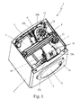
Figure 1 is a perspective view, with parts removed for clarity, of a front-loading laundry washing and drying machine in accordance with the teachings of the present invention; -
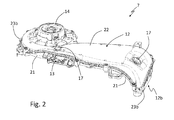
Figure 2 is an enlarged perspective view, with parts removed for clarity, of the hot air duct of the laundry washing and drying machine ofFigure 1 ; whereas -
Figure 3 is a partly exploded perspective view, with parts removed for clarity, of the hot air duct ofFigure 2 . - It is underlined that in the enclosed figures there is illustrated a front-loading washing and drying machine; however it is clear that the present invention can be applied as well to a top-loading washing and drying machine.
- With reference to
Figure 1 ,reference number 1 indicates as a whole a laundry washing anddrying machine 1 that comprises: - a preferably, though not necessarily, substantially parallelepiped-shaped outer
boxlike casing 2 which is preferably structured for resting on the floor; - a preferably, though not necessarily, substantially cylindrical, bell-shaped,
hollow washing tub 3 which is suspended in floating manner inside thecasing 2 with its front opening or mouth directly facing a laundry loading/unloading pass-through opening provided in thefront wall 2a of theboxlike casing 2; and - a substantially cylindrical, bell-shaped revolving drum (not shown) which is structured for housing the laundry to be washed, and is housed in axially rotating manner inside the
washing tub 3 so as to be able to freely rotate about its longitudinal reference axis (L infigure 1 ). - In the example shown,
washing tub 3 is advantageously suspended in floating manner insidecasing 2 via a suspension system preferably comprising a number of coil springs (not shown) and vibration dampers (not shown); and the front opening/mouth ofwashing tub 3 is preferably connected in watertight manner to the laundry loading/unloading opening onfront wall 2a via a substantially cylindrical, elastically-deformable bellows (not shown). - The revolving drum is preferably arranged inside washing
tub 3 so that the drum front opening is directly faced/aligned to the laundry loading/unloading opening onfront wall 2a, and so that the rotation axis of the drum is preferably locally substantially coincident with the substantially horizontally-oriented, longitudinal reference axis L ofwashing tub 3. - With reference to
Figure 1 , the front-loading laundry washing anddrying machine 1 preferably furthermore comprises: - a
porthole door 4 which is preferably hinged to thefront wall 2a ofcasing 2 to rotate about a preferably, though non necessarily, vertically-oriented reference axis to and from a closing position in which the peripheral border of theporthole door 4 rests completely onfront wall 2a for closing the laundry loading/unloading opening and watertight sealing thewashing tub 3; - an electric motor assembly (not shown) which is structured for driving into rotation the revolving drum about its longitudinal reference axis L inside the
washing tub 3; and - a water and detergent supplying assembly (not shown) which is structured for selectively feeding into the
washing tub 3, according to the selected washing cycle, a given amount of detergent, softener and/or other washing agent suitably mixed with the fresh water arriving from the water mains, or simply a given amount of fresh water arriving from the water mains. - The
laundry washing machine 1 is provided with a, preferably closed-circuit,air duct assembly 5 which is structured to circulate inside the washing tub 3 a stream of hot air having a low moisture content, and which flows through the revolving drum and over the laundry located inside the drum to rapidly dry the laundry. - The
air duct assembly 5 is structured for: - gradually drawing air from
washing tub 3; - cooling down the air arriving from
washing tub 3 so to extract and retain the surplus moisture in the air; - heating the dehumidified air to a predetermined temperature preferably higher than that of the air arriving from
washing tub 3; - feeding the heated, dehumidified air back into the
washing tub 3, where it flows over the laundry stored inside the revolving drum to rapidly dry the laundry. - With reference to
Figures 1 ,2 and3 , theair duct assembly 5 is housed inside theboxlike casing 2 and advantageously comprises: - an
air cooling device 6 which is preferably attached to the back ofwashing tub 3, is fluidly connected to washingtub 3 preferably on the bottom of the latter, and is structured to cool down the air arriving fromwashing tub 3 so to extract the surplus moisture in the air drawn fromwashing tub 3; and - an
air heating device 7 which is rigidly attached to thewashing tub 3, is fluidly connected to both thewashing tub 3 and theair cooling device 6 to allow the dehumidified air to flow from theair cooling device 6 to thewashing tub 3, and is structured to heat up the dehumidified air arriving from theair cooling device 6 before this air returns back intowashing tub 3. - In the example shown, the
air cooling device 6 preferably comprises a cold-water condenser which is attached/integrated to/on the back ofwashing tub 3, and which uses a rain/shower of cold water arriving from the water mains to cool down the moist air that arrives fromwashing tub 3 and flows upwards on the back ofwashing tub 3 up to the top of the later. - With reference to
Figures 1 ,2 and3 , theair heating device 7 advantageously comprises ahot air duct 7 which is rigidly attached preferably to the top ofwashing tub 3, and preferably comprises one or more of the following components: - a tubular
outer body 12 which is structured for being firmly fixed to washingtub 3, preferably on the top of the latter, preferably with a first opening ormouth 12a fluidly connected to, i.e. in direct communication with, theair cooling device 6, and preferably with a second opening ormouth 12b fluidly connected to, i.e. in direct communication with, the inside of the bellows (not shown) connecting thewashing tub 3 to the laundry loading/unloading opening onfront wall 2a ofcasing 2, or directly with the inside ofwashing tub 3, preferably close to the front opening ofwashing tub 3; - an air-
heating device 13, for example a resistor, which is housed insidetubular body 12, and is structured to heat up, when electrically powered, the air that flows acrosstubular body 12; - an electric
centrifugal fan 14 or other air-pumping device which is preferably housed insidetubular body 12, preferably upstream of air-heating device 13, and is structured to circulate acrosstubular body 12 an airflow that subsequently flows across thewashing tub 3 and theair cooling device 6 for finally returning back totubular body 12. - In the example shown, the air-
heating device 13 is preferably rigidly fixed in a suspended manner to a mid section oftubular body 12 via ametal supporting bracket 16 which in turn rests, and is rigidly fixed to, the inner surface oftubular body 12. -
Centrifugal fan 14, is preferably recessed on a portion oftubular body 12 suitably shaped to form the outer volute or impeller hosing ofcentrifugal fan 14. - Preferably, though not necessarily, the
hot air duct 7 furthermore comprises one ormore temperature sensors 17 which are located inside, or faced to the inside of,tubular body 12 and are structured for measuring the temperature of the air flowing insidetubular body 12, preferably close to the second opening ormouth 12b of thetubular body 12. - With reference to
Figures 2 and3 ,tubular body 12 preferably, but not necessarily, comprises at least two complementary hemi-shells peripheral edges tubular body 12, and anintermediate sealing gasket 23 which is structured for being interposed between theperipheral edges shells shells - At least one of the hemi-
shells washing tub 3. - The
intermediate sealing gasket 23 comprises a flexiblemain body 23a, preferably substantially cable-shaped, which is made of an elastomeric material and is bended/profiled so as to match with the shape of theperipheral edges shells peripheral edges shells shells main body 23a is preferably substantially circular in shape. - Advantageously the
main body 23a of the sealinggasket 23 can be closed (i.e. having a closed/annular perimeter or profile), as in the embodiment illustrated in enclosed figures, such that if forms a sealing ring; in another embodiment, not illustrated, themain body 23a of the sealinggasket 23 can be open (i.e. having an open perimeter or profile). - With reference to
Figures 2 and3 , theintermediate sealing gasket 23 is furthermore provided with one or more elastic protrusions (or projections) 23b which are conveniently spaced along themain body 23a, and each of which is made of an elastic material and protrudes from themain body 23a so as to jut out of thetubular body 12. - In another advantageous embodiment, not illustrated, one or more elastic protrusions (or projections) may be fixed to the
tubular body 12 in other possible ways, for example they may be over-molded (over-injected) on the external surface of thetubular body 12, so as to locally protect thetubular body 12 from the bumps (collisions, impacts); in this advantageous embodiment thetubular body 12 may comprise the above described hemi shells and gasket (with or without further elastic protrusions or projections projecting form the gasket), or not (i.e. the tubular body may have a different structure). - In the example shown, each protrusion (or projection) is preferably, though not necessarily, made of the same elastomeric material of the cable-shaped
main body 23a. - Advantageously the one or more protrusions/
projections 23b are arranged in such a way that they are positioned between thetubular body 12 and theouter casing 2, so as to locally protect thetubular body 12 from the bumps (collisions, impacts) against the outer casing 2 (and clearly also to locally protect theouter casing 2 from the bumps of the tubular body 12). - With reference to
Figure 3 , in the example shown, theperipheral edge shells 21 and 22 (both hemi-shells in the example shown) is furthermore preferably provided with a longitudinal grove (or seat) 25, and the cable-shapedmain body 23a ofgasket 23 is preferably shaped/dimensioned so as to be at least partly recessed inside the longitudinal grove/seat 25 and preferably also compressed/ deformed so as to substantially fill up the longitudinal grove/seat 25. - Advantageously in this embodiment each protrusion (or projections) 23b, is shaped to protrude from the cable-shaped
main body 23a so as to come out of thelongitudinal grove 25 and then jut out of the outer surface oftubular body 12, to form a corresponding outer shock-absorbingprotrusion 23b oftubular body 12. In this case the grove orseat 25 is preferably provided, in correspondence of one or more of the protrusion/projections 23b, with aslot 26 through which the protrusion/projections 23b can protrude externally from the grove or seat, and therefore from thetubular body 12. In this case the protrusions /orprojections 23b and the correspondingslots 26 provided in the grove/seat may serve, during the assembly of thehot air duct 7, as centering elements for the correct reciprocal positioning of the sealing element and of thetubular body 12, thus also greatly simplifying the assembly of theair duct assembly 5. - In addition to the above, with reference to
Figures 2 and3 , in the example shown thetubular body 12 is preferably composed by a substantially basin-shaped, lower hemi-shell 21 which is structured for being rigidly fixed to the top of thewashing tub 3 preferably via a number of anchoring screws 18, and by a substantially lid-shaped, upper hemi-shell 22 which is shaped/dimensioned to rest in abutment on the annularupper rim 21a of hemi-shell 21 to completely close the basin-shaped lower hemi-shell 21. - The basin-shaped lower hemi-
shell 21 is furthermore preferably provided with two coupling collars/manifolds which protrude downwards from the bottom of the hemi-shell 21 and are shaped/dimensioned to fit/couple in substantially airtight manner respectively with the air escape mouth of theair cooling device 6 and with an auxiliary pass-through opening provided either on the cylindrical bellows connectingwashing tub 3 to the laundry loading/unloading opening onfront wall 2a, or directly on the body ofwashing tub 3. - Preferably the substantially basin-shaped, lower hemi-
shell 21 is furthermore shaped/dimensioned so to directly house the air-heating device 13, and themetal supporting bracket 16 that supports air-heating device 13 is preferably rigidly fixed to the bottom of the hemi-shell 21, preferably between the two coupling collars/manifolds that protrude downwards from the bottom of hemi-shell 21. - The substantially lid-shaped, upper hemi-
shell 22, is preferably, though not necessarily, structured/shaped to directly support thetemperature sensors 17 preferably aligned immediately above the coupling collar/manifold that connects the hemi-shell 21 directly or indirectly to the inside ofwashing tub 3. - A first portion of the outer volute of
centrifugal fan 14 is furthermore preferably, though not necessarily, provided directly on the substantially basin-shaped, lower hemi-shell 21 locally substantially coaxial to the coupling collar/manifold structured to be fitted/coupled to the air escape mouth of theair cooling device 6, whereas a second complementary portion of the outer volute ofcentrifugal fan 14 is provided on the lid-shaped upper hemi-shell 22, so that the complete outer volute ofcentrifugal fan 14 is composed when the upper and lower hemi-shells - In the example shown, both upper and lower hemi-
shells - With reference to
Figure 3 , in the example shown the cable-shapedmain body 23a of sealinggasket 23 is preferably substantially annular in shape (i.e. it is a sealing ring); preferably themain body 23a of the sealinggasket 23 is so shaped and arrange to exactly match with the annularupper rim 21a of the lower hemi-shell 21. - One or more of the protrusions (or projections) 23b of sealing
gasket 23 are furthermore preferably substantially L-shaped so as to bend (or curve) sideways, when out oftubular body 12, and extends locally substantially tangent or close to the outer surface oftubular body 12 to form corresponding outer shock-absorbingpads 23b onto the outer surface oftubular body 12. - In the examples shown, the
intermediate sealing gasket 23 is preferably made of an elastomeric plastic material and is made in one piece via an injection molding process. - General operation of the front-loading laundry washing and drying
machine 1 is clearly inferable from the above description, with no further explanation required. - The advantages connected to the particular structure of the hot air duct according to invention are large in number.
- First of all, being integrally provided with several shock-absorbing protrusions/projections onto the outer surface of tubular body, the hot air duct is effectively protected from the bumps due to the shaking of the tub to which the hot air duct is attached, without increasing the complexity and the production costs of the machine.
- Moreover a plenty of shock-absorbing pads conveniently attached on the lateral walls of the boxlike casing is no more necessary, which greatly simplifying the assembly of the front-loading laundry washing and drying machine.
- Clearly, changes may be made to either the laundry washing and drying machine as described herein without, however, departing from the scope of the present invention.
- In a less sophisticated embodiment of the
hot air duct 7, the cable-shapedmain body 23a of theintermediate sealing gasket 23 may be bended so as to match with the shape of only a limited section of theperipheral edges shells main body 23a so as to jut out of the longitudinal slit delimited, on the outer surface oftubular body 12, by this limited section of theperipheral edges shells
Claims (12)
- Laundry washing and drying machine (1) comprising:- an outer casing (2),- a hollow washing tub (3) suspended in floating manner inside said casing (2),- a hot air duct (7) attached onto said washing tub (3) and comprising a tubular body (12) structured for being crossed by an airflow,
characterized in that
said hot air duct (7) is provided with at least one elastic protrusion/projection (23b) protruding from said tubular body (12) in such a way to locally protect said tubular body (12) from the bumps. - Laundry washing and drying machine (1), according to claim 1, wherein said tubular body (12) comprises at least two hemi-shells (21, 22) reciprocally coupled to compose/form said tubular body (12), and an intermediate sealing gasket (23) interposed between said at least two hemi-shells (21, 22) to seal said hemi-shells (21, 22) one another, said intermediate sealing gasket (23) comprising a main body (23a) interposed between said two or more hemi-shells (21, 22) when said hemi-shells (21, 22) are coupled one another, said intermediate sealing gasket (23) comprising said at least one elastic protrusion/projection (23b) protruding from the main body (23a) and from said tubular body (12) in such a way to locally protect said tubular body (12) from the bumps.
- Laundry washing and drying machine according to Claim 2, wherein the main body (23a) of the intermediate sealing gasket (23) is made of an elastomeric material.
- Laundry washing and drying machine according to Claim 2 or 3, wherein said at least one protrusion/projection (23b) of the intermediate sealing gasket (23) is made of the same material of the main body (23a).
- Laundry washing and drying machine according to one or more of claims 2 to 4, wherein the peripheral edge (21a, 22a) of at least one of said hemi-shells (21, 22) is provided with a longitudinal grove or seat (25), and the main body (23a) of the sealing gasket (23) is shaped/dimensioned so as to be at least partly recessed into said longitudinal grove or seat.
- Laundry washing and drying machine according to claim 5, wherein said grove or seat (25) is provided, in correspondence of one or more of said protrusion/projections (23b), with a slot (26) through which the respective protrusion/projections (23b) protrude externally from said grove or seat (25), and therefore from said tubular body (12).
- Laundry washing and drying machine according to one or more of claims 2 to 6, wherein the protrusion/projection (23b) of the intermediate sealing gasket (23) is substantially L-shaped so as to bend sideways, when out of the tubular body (12), and extends locally substantially tangent or close to the outer surface of the tubular body (12), so as to form a corresponding outer shock-absorbing pad (23b) onto the outer surface of tubular body (12).
- Laundry washing and drying machine according to one or more of claims 2 to 7, wherein the main body (23a) of the intermediate sealing gasket (23) is substantially annular in shape.
- Laundry washing and drying machine according to one or more of claims 2 to 7, wherein the main body (23a) of the intermediate sealing gasket (23) is open in shape.
- Laundry washing and drying machine according to one or more of claims 2 to 9, wherein a plurality of said protrusions/projections (23b) is spaced along said main body (23a).
- Laundry washing and drying machine according to claim 1, wherein said at least one protrusion/projection (23b) is over-molded on the external surface of said tubular body (12).
- Laundry washing and drying machine according to any one of the preceding claims, wherein said at least one protrusion/projection (23b) is arranged in such a way that it is positioned between said tubular body (12) and said outer casing (2), so as to locally protect said tubular body (12) from the bumps against said outer casing (2), and vice versa.
Priority Applications (2)
| Application Number | Priority Date | Filing Date | Title |
|---|---|---|---|
| EP11193953.4A EP2604747A1 (en) | 2011-12-16 | 2011-12-16 | Household laundry washing and drying machine |
| PCT/EP2012/075182 WO2013087673A1 (en) | 2011-12-16 | 2012-12-12 | Household laundry washing and drying machine |
Applications Claiming Priority (1)
| Application Number | Priority Date | Filing Date | Title |
|---|---|---|---|
| EP11193953.4A EP2604747A1 (en) | 2011-12-16 | 2011-12-16 | Household laundry washing and drying machine |
Publications (1)
| Publication Number | Publication Date |
|---|---|
| EP2604747A1 true EP2604747A1 (en) | 2013-06-19 |
Family
ID=47458900
Family Applications (1)
| Application Number | Title | Priority Date | Filing Date |
|---|---|---|---|
| EP11193953.4A Withdrawn EP2604747A1 (en) | 2011-12-16 | 2011-12-16 | Household laundry washing and drying machine |
Country Status (2)
| Country | Link |
|---|---|
| EP (1) | EP2604747A1 (en) |
| WO (1) | WO2013087673A1 (en) |
Cited By (1)
| Publication number | Priority date | Publication date | Assignee | Title |
|---|---|---|---|---|
| DE102015100315A1 (en) | 2015-01-12 | 2016-07-14 | Miele & Cie. Kg | Dryer with rear air duct |
Families Citing this family (2)
| Publication number | Priority date | Publication date | Assignee | Title |
|---|---|---|---|---|
| CN114150485B (en) * | 2021-12-07 | 2023-07-11 | 珠海格力电器股份有限公司 | Drying system and washing machine with same |
| CN118727407A (en) * | 2023-03-29 | 2024-10-01 | 重庆海尔滚筒洗衣机有限公司 | Drying assembly and washing equipment having the same |
Citations (5)
| Publication number | Priority date | Publication date | Assignee | Title |
|---|---|---|---|---|
| US5934107A (en) * | 1997-02-18 | 1999-08-10 | Samsung Electronics Co., Ltd. | Clothes washing machine having an impact damper |
| WO2007021134A2 (en) * | 2005-08-19 | 2007-02-22 | Lg Electronics, Inc. | Drying duct assembly and washing machine having the same |
| US20100058815A1 (en) * | 2008-04-30 | 2010-03-11 | Lg Electronics Inc. | Heating part and laundry treating machine having the same |
| WO2010100114A1 (en) | 2009-03-02 | 2010-09-10 | BSH Bosch und Siemens Hausgeräte GmbH | Sealing mechanism and household appliance provided with the sealing mechanism |
| DE102010029491A1 (en) * | 2009-06-17 | 2011-01-13 | BSH Bosch und Siemens Hausgeräte GmbH | Assembly and household tumble dryer with this assembly |
Family Cites Families (1)
| Publication number | Priority date | Publication date | Assignee | Title |
|---|---|---|---|---|
| US7322125B2 (en) * | 2004-04-12 | 2008-01-29 | Lg Electronics Inc. | Dry heater fixing unit of drum-type washing machine combined with drier |
-
2011
- 2011-12-16 EP EP11193953.4A patent/EP2604747A1/en not_active Withdrawn
-
2012
- 2012-12-12 WO PCT/EP2012/075182 patent/WO2013087673A1/en not_active Ceased
Patent Citations (5)
| Publication number | Priority date | Publication date | Assignee | Title |
|---|---|---|---|---|
| US5934107A (en) * | 1997-02-18 | 1999-08-10 | Samsung Electronics Co., Ltd. | Clothes washing machine having an impact damper |
| WO2007021134A2 (en) * | 2005-08-19 | 2007-02-22 | Lg Electronics, Inc. | Drying duct assembly and washing machine having the same |
| US20100058815A1 (en) * | 2008-04-30 | 2010-03-11 | Lg Electronics Inc. | Heating part and laundry treating machine having the same |
| WO2010100114A1 (en) | 2009-03-02 | 2010-09-10 | BSH Bosch und Siemens Hausgeräte GmbH | Sealing mechanism and household appliance provided with the sealing mechanism |
| DE102010029491A1 (en) * | 2009-06-17 | 2011-01-13 | BSH Bosch und Siemens Hausgeräte GmbH | Assembly and household tumble dryer with this assembly |
Cited By (2)
| Publication number | Priority date | Publication date | Assignee | Title |
|---|---|---|---|---|
| DE102015100315A1 (en) | 2015-01-12 | 2016-07-14 | Miele & Cie. Kg | Dryer with rear air duct |
| DE102015100315B4 (en) | 2015-01-12 | 2018-03-01 | Miele & Cie. Kg | Dryer with rear air duct and method for producing such a rear air duct |
Also Published As
| Publication number | Publication date |
|---|---|
| WO2013087673A1 (en) | 2013-06-20 |
Similar Documents
| Publication | Publication Date | Title |
|---|---|---|
| KR101397059B1 (en) | Apparatus with drying function | |
| EP2634301B1 (en) | Household laundry washing and drying machine with a condensing device and method of operating this machine | |
| EP2412861B1 (en) | Laundry washing and drying machine | |
| EP2843114B1 (en) | Rotary-drum laundry dryer | |
| EP2631353B1 (en) | Rotary-drum laundry dryer | |
| EP2865803B1 (en) | Rotary-drum laundry dryer | |
| WO2013087673A1 (en) | Household laundry washing and drying machine | |
| EP2604748A1 (en) | Household laundry washing and drying machine | |
| EP3039180A1 (en) | Rotary-drum laundry dryer | |
| JP6403415B2 (en) | Drum type washer / dryer | |
| EP2604749B1 (en) | Household laundry washing and drying machine | |
| EP2631356B1 (en) | Rotary-drum laundry dryer | |
| EP2631357A1 (en) | Rotary-drum laundry dryer | |
| EP2843115A1 (en) | Rotary-drum laundry dryer | |
| EP2604750A1 (en) | Household laundry washing and drying machine | |
| EP3039181B1 (en) | Rotary-drum laundry dryer | |
| EP2631352B1 (en) | Rotary-drum laundry dryer | |
| EP2843113A1 (en) | Rotary-drum laundry dryer |
Legal Events
| Date | Code | Title | Description |
|---|---|---|---|
| PUAI | Public reference made under article 153(3) epc to a published international application that has entered the european phase |
Free format text: ORIGINAL CODE: 0009012 |
|
| AK | Designated contracting states |
Kind code of ref document: A1 Designated state(s): AL AT BE BG CH CY CZ DE DK EE ES FI FR GB GR HR HU IE IS IT LI LT LU LV MC MK MT NL NO PL PT RO RS SE SI SK SM TR |
|
| AX | Request for extension of the european patent |
Extension state: BA ME |
|
| STAA | Information on the status of an ep patent application or granted ep patent |
Free format text: STATUS: THE APPLICATION IS DEEMED TO BE WITHDRAWN |
|
| 18D | Application deemed to be withdrawn |
Effective date: 20131220 |