EP2604741A1 - Lighting apparatus for laundry machines - Google Patents
Lighting apparatus for laundry machines Download PDFInfo
- Publication number
- EP2604741A1 EP2604741A1 EP11193993.0A EP11193993A EP2604741A1 EP 2604741 A1 EP2604741 A1 EP 2604741A1 EP 11193993 A EP11193993 A EP 11193993A EP 2604741 A1 EP2604741 A1 EP 2604741A1
- Authority
- EP
- European Patent Office
- Prior art keywords
- light
- drum
- laundry machine
- laundry
- emitting element
- Prior art date
- Legal status (The legal status is an assumption and is not a legal conclusion. Google has not performed a legal analysis and makes no representation as to the accuracy of the status listed.)
- Granted
Links
Images

Classifications
-
- D—TEXTILES; PAPER
- D06—TREATMENT OF TEXTILES OR THE LIKE; LAUNDERING; FLEXIBLE MATERIALS NOT OTHERWISE PROVIDED FOR
- D06F—LAUNDERING, DRYING, IRONING, PRESSING OR FOLDING TEXTILE ARTICLES
- D06F37/00—Details specific to washing machines covered by groups D06F21/00 - D06F25/00
- D06F37/26—Casings; Tubs
- D06F37/267—Tubs specially adapted for mounting thereto components or devices not provided for in preceding subgroups
-
- D—TEXTILES; PAPER
- D06—TREATMENT OF TEXTILES OR THE LIKE; LAUNDERING; FLEXIBLE MATERIALS NOT OTHERWISE PROVIDED FOR
- D06F—LAUNDERING, DRYING, IRONING, PRESSING OR FOLDING TEXTILE ARTICLES
- D06F39/00—Details of washing machines not specific to a single type of machines covered by groups D06F9/00 - D06F27/00
-
- D—TEXTILES; PAPER
- D06—TREATMENT OF TEXTILES OR THE LIKE; LAUNDERING; FLEXIBLE MATERIALS NOT OTHERWISE PROVIDED FOR
- D06F—LAUNDERING, DRYING, IRONING, PRESSING OR FOLDING TEXTILE ARTICLES
- D06F58/00—Domestic laundry dryers
- D06F58/02—Domestic laundry dryers having dryer drums rotating about a horizontal axis
- D06F58/04—Details
Definitions
- the present invention relates to laundry machines, such as washing machines, washing/drying machines and drying machines, both for domestic and professional use. More particularly, the present invention relates to drum lighting for such laundry machines.
- Each household and professional laundry machine - such as washing machine, washing/drying machines and drying machines - typically comprises, among other components, an inner compartment accessible by a user ( e.g. , through a proper access door and/or lid) for loading/unloading the laundry; in the case of a washing machine or washing/drying machine the inner compartment includes a washing tub housing a rotatable drum in which the laundry can be loaded/unloaded, while in the case of a drying machine the inner compartment includes a rotatable drum in which the laundry can be loaded/unloaded.
- a lighting system which substantially comprises one or more lightning device - incandescent light lamps, fluorescent light lamps, discharge light lamps or solid-state lighting devices (e.g ., high power LEDs) - acting as corresponding light-emitting elements for illuminating the drum.
- the lighting system may be arranged inside the drum ( e.g ., in drum walls and/or in lifters inside the drum).
- the Applicant has recognized that the approach providing a light-emitting element within the drum is intrinsically difficult to implement - substantially due to the fact that the light-emitting element, which is arranged on a portion of the machine ( i.e ., the drum) adapted to rotate with respect to the casing of the machine, has to be electrically connected with the supply electric assembly, which is instead stationary with respect to the casing.
- laundry items stored inside the drum cover the light-emitting element, thus impeding a functional enlightenment of the drum.
- the light-emitting element is provided in a frame or hopper provided in correspondence of the loading/unloading opening of the casing and encompassing the loading/unloading opening.
- This solution implies several drawbacks, too. For example, properly installing the light-emitting element within the frame/hopper is a difficult and time-consuming task. Furthermore, the frame/hopper robustness may be lowered by the insertion of the light-emitting element. Moreover, it is difficult to effectively direct the light radiation emitted by the light-emitting element towards the inside of the drum.
- DE 4026547 discloses a washing machine that incorporates a horizontally rotating perforated laundry drum contained inside a washing solution container.
- the washing solution container jacket features a detergent and/or fresh water supply opening and/or vent opening with an associated supply line.
- An illuminating body is built into the supply line in such a way that its light discharge face is directed at the drum jacket.
- the machine provides for the possibility of illuminating the inner space of the drum through the drum perforation.
- the illuminating body requires no special fastening as it is integrated in the supply line.
- the Applicant has found that enlightening the inside of the drum through bores of the same has a low efficiency. Indeed, the bores in the drum have usually a small diameter, this lead to a scarce enlightening of the inside of the drum, since the light radiation permeating the inside of the drum results scattered and has a low intensity.
- the Applicant has handled the problem of devising a satisfactory solution able to provide a satisfactory enlightenment of the inside of the drum, thus facilitating inspection thereof and laundry loading/unloading tasks, at the same time, overcoming the above-discussed drawbacks.
- a lightning system having a light-emitting element provided in a stationary part of the laundry machine (for example, in the case of a washing machine or a washing/drying machines, the stationary part may advantageously be the washing tub, which is stationary with respect to the rotating drum, or, in the case of a drying machines, which typically is not provided with a tub, the stationary part may be the casing or the frame of the machine, which is stationary with respect to the rotating drum), a light permeable portion on the drum arranged in such a way that a light-radiation emitted by the light-emitting element is able to enter the drum via such a light-permeable portion, and a transparent element mounted inside the drum in correspondence of the light-permeable portion, adapted to allow the light radiation emitted by the light-emitting element, and crossing the light-permeable portion, to reach and thoroughly enlightening the inside of the drum.
- the laundry machine comprises an outer casing, which rotatably houses a drum for accommodating the items to be treated, and a lighting system for enlightening the inside of the drum.
- the lighting system includes a light-emitting element provided on a stationary portion of the laundry machine, for emitting a light radiation towards a drum wall.
- the drum comprises at least one light-permeable portion formed in the drum wall.
- the lightning system further comprises a transparent element mounted inside the drum in correspondence of said light-permeable portion, adapted to allow the light radiation emitted by said light-emitting element, and crossing said light-permeable portion, to reach the inside of the drum.
- the drum may be adapted to be rotated in a predetermined position in which said light-permeable portion and said transparent element are axially aligned with the light-emitting element.
- the transparent element may be adapted to direct the light radiation towards a central portion inside the drum.
- the transparent element may be adapted to uniformly diffuse the light radiation.
- the laundry machine may further comprise a cover element having a hollow main body and comprising said transparent element, said cover element being mounted on the drum wall over said light-permeable portion.
- the transparent element may be provided on a top edge portion of the hollow main body.
- the hollow main body may comprise an open base surface opposite to the top edge portion, said open base surface encompassing the light-permeable portion.
- the transparent element may engage the hollow main body of the cover element by means of a snap-fit engagement.
- the cover element may be a lifter adapted to improve the tumbling of items during the laundry machine operation.
- the laundry machine may further comprise a holder in the stationary portion of the laundry machine for housing the light-emitting element.
- the laundry machine may further comprise a light focuser, coupled with the light-emitting element adapted to focus the light radiation generated by said light-emitting element towards the drum wall.
- the laundry machine may further comprise a transparent cap adapted to close the holder, for sealing the light-emitting element away from liquids and/or moisture comprised in the stationary portion of the laundry machine.
- FIG. 1 Considering Figure 1 and Figure 2 together, there are shown a cross-sectional and enlarged side views, respectively, of a laundry machine 100 according to an embodiment of the present invention.
- the laundry machine 100 is a machine for treating laundry (such has a laundry washing machine, a laundry washing/drying machine, a laundry drying machine etc .) of the top-loading type.
- laundry machines of the front-loading type may also benefit from the solution according to the present invention.
- the laundry machine 100 comprises a substantially parallelepiped-shaped casing 105 that, preferably, although not necessarily, encloses a substantially cylindrical-shaped tub 110 (it is underlined that the tub is advantageously provided in the case of a washing machine or a washing/drying machine, while the tub is not provided in case of a drying machine), wherein the laundry is treated, along with any other component of the laundry machine 100 necessary for the operation (e.g ., hydraulic, electronic and electromechanical apparatuses well known in the art and, therefore, not herein described for sake of conciseness).
- any other component of the laundry machine 100 necessary for the operation e.g ., hydraulic, electronic and electromechanical apparatuses well known in the art and, therefore, not herein described for sake of conciseness.
- the tub 110 is preferably fixed to a frame 115 (which substantially supports the casing 105 and any other component comprised in the laundry machine 100), preferably by supporting elastic coils (one of which visible in Figure 1 , therein identified with the numeral 120 ), and shock (and vibration) absorber elements, such as two shock absorbers 125 (which absorb jolts of the tub during operation).
- the tub 110 houses a substantially cylindrical-shaped rotating drum 130, which, in operation, rotates about an axis A in order to tumble the laundry to be washed.
- a substantially cylindrical-shaped rotating drum 130 which, in operation, rotates about an axis A in order to tumble the laundry to be washed.
- one or more baffles or lifters 135a and 135b are mounted on a drum wall 130a (parallel to a drum rotation axis A) in the inside of the drum 130 for enhancing the tumbling action on laundry performed in operation by the same.
- the drum may advantageously be enclosed by the casing of the laundry machine; for example, in the case of a drying machine, the drum is preferably rotatably supported by a number of wheels provided in the base of the machine, inside the casing.
- an opening 140 is advantageously provided on the top of the washing machine 100.
- the opening 140 is closable by a lid (removed in the Figure 1 ), which is preferably, although not necessarily, hingeably connected to the casing 105 by means of a hinge (not shown in the figure).
- the lid is adapted to pivot from a closed position - wherein the lid closes the opening 140, impeding the access to the tub 110 - to an open position - wherein the lid is pivoted to an angle, preferably, equal to, or greater than, 90° with respect to the closed position, allowing the access to the tub 110.
- a drum opening is provided in the drum wall 130a and a door 145 is provided for closing the same during operation.
- the door 145 comprises a first door leaf 145a and a second door leaf 145b.
- the first door leaf 145a is advantageously hinged to the drum 130 by a first leaf hinge 150a, while the second door leaf 145b is hinged to the drum 130 by a second leaf hinge 150b.
- interlocking elements (not shown in the figure) block the first and the second door leaves 145a and 145b to one another, thus impeding any unwanted (and harmful) opening of the door 145 during operation ( i.e ., when the drum rotates).
- the door may comprise a single door leaf; the following description refers to a door comprising two door leaves, but it can as well be applied to a door comprising a single door leaf (for example when, in the following, reference is made to the "first door leaf', it can be read also as “single door leaf' in case the door comprises only a single door leaf).
- the laundry machine 100 In order to have the door 145 in an open position (shown in the Figure 1 ), the laundry machine 100, at the end of the operation, preferably aligns the door 145 with the opening 140 - alternatively or in addition, the user may align the door 145 with the opening 140 manually -; then the interlocking elements have to be unlocked, and the first and second door leaves 140a and 140b are preferably automatically rotated (preferably by elastic devices provided preferably in their hinges) until they abuts against - or reach a predetermined minimum distance from - a bellow 155 connecting the tub 110 to the border of the opening 140, or, if the bellows is not provided, abuts directly against the border of the opening 140.
- the inside of the drum 130 is accessible (through the drum opening) by the user for loading/unloading the laundry stored therein.
- a user interface 160 for the selection of laundry treatment parameters (e.g ., a temperature of a treatment fluid, a maximum rotation speed of the drum 130, etc .), is provided, preferably on the top of the casing 105.
- laundry treatment parameters e.g ., a temperature of a treatment fluid, a maximum rotation speed of the drum 130, etc .
- a lighting system is provided for enlightening the inside of the drum.
- the lighting system comprises at least a light-emitting element 165 provided on a stationary portion of the machine (i.e ., any suitable part of the laundry machine for supporting the light-emitting element that does not rotates with the drum in operation; e.g., the tub, the casing the frame etc .), adapted to enlighten the inside of the drum.
- the light-emitting element 165 is arranged in the stationary portion of the machine in such a way that a light-radiation emitted by such a light-emitting element 165 reaches the drum 130, directly, or via a light permeable and/or conductive element, for example a light-guide, not illustrated.
- a light-permeable portion e.g. , an aperture 202 in the drum wall, or a transparent insert fixed in any suitable manner - e.g . by over-molding - on the drum wall 130a or constructed in a single piece with the same
- a light-permeable portion is provided in the drum wall 130a, which light-permeable portion is arranged in such a way that a light radiation emitted by the light-emitting element 165 and reaching the drum wall 130a can enter the drum 130 by the light-permeable portion, thus allowing a thoroughly enlightenment of the inside of the drum 130,
- the light-permeable portion of the drum wall 130a and the light emitting element 165 are arranged in such a way that when the drum 130 is in a predetermined angular position (for example, in the case of a top-loading washing machine, is in the position allowing the opening of the door 145) the light emitting element 165 faces and is aligned with the light-permeable portion of the drum wall 130a, so that light enters the drum 130 and illuminates the inside of the latter.
- a cover element may be provided over the light permeable portion of the drum wall 130a, such cover element preferably comprising a transparent element for allowing the light radiation to enter inside the drum 130.
- a light-emitting element 165 may advantageously be provided on a wall 110a of the tub 110.
- a light-emitting element 165 may be provided on an internal surface of the casing, on the frame of the laundry machine or on an electronic board comprised in the laundry machine ( e.g ., the electronic board comprising an electronic control unit of the laundry machine), and positioned/arranged in such a way that a light radiation emitted by the light-emitting element 165 is able to enter the drum 130 via such the light-permeable portion of the wall 130a of the latter.
- a light-permeable portion such as an aperture 202 is preferably provided on the drum wall 130a.
- the light-permeable portion may advantageously be formed by a glass or a transparent polymer insert fixed in the drum wall 130a in any suitable manner, or monolithically formed with the same ( e.g . by over-molding); for example, in the case of a drying machine, the light-permeable portion may advantageously be monolithically formed with the drum wall, thus maintaining the inside of the drum sealed from the rest of the laundry machine.
- an axial alignment i.e ., both the light-emitting element 165 and the light-permeable portion - e.g. the aperture 202 - share a same symmetry axis B) between the light-emitting element 165 and the light-permeable portion - e.g . the aperture 202 - is possible (as will be described in greater detail in the following), since the tub wall 110a and the drum wall 130a are parallel one another.
- the light-emitting element 165 is preferably mounted in a holder 205, for example a recess in the tub wall.
- the light-emitting element 165 may comprise any suitable lighting device 210, such as an incandescent light lamp, a fluorescent light lamp, a discharge light lamp or a solid-state lighting device (e.g ., a LED - Light Emitting Diode).
- the lightning device 210 might comprise more than just one of the lighting devices listed above (e.g. , the lightning device 210 may comprise a plurality of LEDs in a strip or a ring arrangement) in order to obtain a desired illumination intensity ( i.e ., able to grant a satisfactory enlightenment of the drum 130).
- the light-emitting element may be enclosed in a box-like holder affixed, for example, to a casing or a frame portion of the laundry machine.
- the lightning device 210 may advantageously be supplied with electric power in any known way; for example, the lightning device 210 may be supplied by a power circuit comprised in the laundry machine 100, a selective connection with the mains or a battery arrangement (not shown in the figures).
- light-emitting element has not to be interpreted only as a lamp or a similar "light-generating” device, but it refers to any device adapted to emit light radiation, for example the edge of an optical fiber, or of a light-guide ( e.g ., the free edge of a cylinder made of transparent plastics or glass).
- a light-guide e.g ., the free edge of a cylinder made of transparent plastics or glass.
- such device may be adapted to guide light radiation - generated by a lightning device placed elsewhere in the laundry machine - towards the drum.
- a light focuser 215 may be coupled with the light-emitting element 165, designed to focus a light radiation generated by the lightning device 210 preferably towards the drum wall 130a .
- the light focuser 215 may have a shape of a truncated elliptic paraboloid with the light-emitting device 165 placed at a truncated opened end and with the opposite opened end facing the drum 130 .
- a cap 220 made of a transparent material may be provided for closing the holder recess 205 .
- the light-emitting element 165 may be advantageously sealed in the holder 205 , thus, protected from treating liquids and/or moisture comprised in the tub 110 (at least during the operation of the laundry machine 100 ).
- the holder 205 - and, therefore, the light-emitting element 165 - may advantageously be provided in such a way to prevent a user (looking inside the drum 130 ) from being directly hit by the light radiation emitted by the light-emitting element 165, thus preventing glare and dazzling effects.
- the light-emitting element 165 may be provided in a top portion of the tub wall 110a (thus, also the probability of the light radiation resulting hindered by laundry inside the tub is substantially nullified).
- the light-permeable portion, - e.g . the aperture 202, in the drum wall 130a may have any suitable shape ( i.e ., ranging from rectangular to circular) and, preferably, has a size adapted to let pass the whole light radiation emitted by the light-emitting element 165 into the drum 130.
- a cover element, such as the lifter 135b may be advantageously mounted on the drum wall 130a (facing the inside of the drum 130 ) in correspondence of the light-permeable portion (e.g., the aperture 202 ) provided in the drum wall 130a .
- the lifter 135b may be mounted in any know way, such as by means of screws, glue or a snap-fit arrangement. It should be noted that, the lifter 135b , being mounted over the light-permeable portion ( e.g ., the aperture 202 ), prevents laundry in the drum from obstructing such the light-permeable portion ( e.g ., the aperture 202 ), and/or if the light-permeable portion comprises the aperture 202, also prevents laundry form falling in the tub 110 via the aperture 202 (possibly, provoking malfunctions of the laundry machine 100 in operation and/or damaging the laundry itself).
- FIG. 3A and Figure 3B there are schematically shown an isometric view and an isometric exploded view, respectively, of the lifter 135b according to an embodiment of the present invention.
- the lifter 135b advantageously comprises a hollow main body 305 being substantially triangular prism-shaped with an opened base surface.
- the lifter comprises a transparent portion, such as a transparent element 310 adapted to be engaged with the main body 305.
- the engagement between the transparent element 310 and the main body 305 may be provided by a snap-fit arrangement 315.
- the main body 305 and the transparent element 310 may advantageously be made of any suitable material, such as a polymer for the former and a transparent polymer for the latter.
- the transparent element 310 may be provided on a top edge portion 320 of the main body 305 opposed to an open base surface 325 thereof, in order to transmit the light radiation (incoming from the light-emitting element 165, as will be described in following) through the light-permeable portion ( e.g. , the aperture 202) into the drum 130.
- the transparent element 310 may range in length, from a minimum extension - allowing the transmission of light radiation with a sufficient intensity inside the drum 130 -, to a maximum extension, substantially equal to a length of the top edge portion 320 - for the transmission of light radiation with the highest intensity achievable (in this embodiment of the present invention).
- the transparent element 310 may be shaped with a curvature adapted to direct the light radiation towards a central portion (corresponding to the rotation axis A) inside the drum 130 in order to enlightening the same with a high intensity.
- This central portion inside the drum 130 results to be preeminently used by the user during the laundry loading/unloading operations; thus, proper enlightenment of such central portion inside the drum 130 is crucial for the user.
- the transparent element 310 may be shaped with a curvature adapted to uniformly diffuse the light radiation (i.e ., diffusing the light radiation substantially in an isotropic manner) in the inside of the drum 130. In this way, the inside of the drum 130 results substantially completely and evenly enlightened.
- the transparent element may be formed integral ( e.g . by over-molding or co-molding) with the lifter.
- the lifter may be completely made of a transparent material, thus being adapted to transmit the light radiation with any of its parts.
- the lifter advantageously comprises only a transparent main body, itself acting as the transparent element previously described.
- the light-emitting element 165 may be forced to emit a light radiation only when the laundry treatment is not in action (i.e ., when the drum is not rotating). Even more preferably, the light-emitting element 165 may be forced to emit the light radiation only when the drum 130 is in a predetermined position (e.g. , by means of a electromechanical switch, not shown, that closes when the drum 130 is rotated in the predetermined position); for example, when the drum 130 is in a position allowing the drum door 145 to be opened ( i.e ., with both the door leaves 145a and 145b in the open position).
- a predetermined position e.g. , by means of a electromechanical switch, not shown, that closes when the drum 130 is rotated in the predetermined position
- the drum 130 is in a position allowing the drum door 145 to be opened ( i.e ., with both the door leaves 145a and 145b in the open position).
- the lightning device may, advantageously, be adapted to emit a light radiation automatically when the lid (or a door in front-loading type laundry machines) is in the open position.
- a pushbutton (not shown) may be provided in the user interface 160 allowing a user to selectively force the light radiation emission by the light-emitting element 165.
- the lifter 135b is mounted on the drum 130 (covering the light-permeable portion - e.g . the drum aperture 202-) in such a way that, when the drum 130 is in the predetermined position, also the lifter 135b results axially aligned with the light-emitting element 165 (as shown in Figure 1 and Figure 2 ).
- the light-permeable portion e.g . the aperture 202
- the transparent element 310 of the lifter 135b the light radiation emitted by the light emitting source 165 is able to reach into the drum 130 with a sufficient intensity in order to thoroughly enlighten the same.
- the lifter 135b along with transmitting the light radiation into the drum 130 thanks to the transparent element 310, also enhances the tumbling action, as do the lifters known in the art during the laundry machine 100 operation.
- the lifter 135b may be omitted, and a transparent panel (acting as light-permeable element) may be provided in a single-piece construction (single-body) with the drum.
- a transparent panel acting as light-permeable element
- the transparent panel grants a proper sealing of the inside of the drum from the rest of the laundry machine (thus preventing any unwanted moisture and/or steam - present in the drum during operation - dispersion inside the casing and/or in the environment).
- the lightning system according to the present invention is able to provide a satisfactory enlightenment of the inside of the drum, thus facilitating inspection thereof and laundry loading/unloading tasks.
- the lightning system according to the present invention overcomes the above-discussed drawbacks with a robust and cost-effective solution.
Landscapes
- Engineering & Computer Science (AREA)
- Textile Engineering (AREA)
- Main Body Construction Of Washing Machines And Laundry Dryers (AREA)
- Detail Structures Of Washing Machines And Dryers (AREA)
Abstract
Description
- The present invention relates to laundry machines, such as washing machines, washing/drying machines and drying machines, both for domestic and professional use. More particularly, the present invention relates to drum lighting for such laundry machines.
- Each household and professional laundry machine - such as washing machine, washing/drying machines and drying machines - typically comprises, among other components, an inner compartment accessible by a user (e.g., through a proper access door and/or lid) for loading/unloading the laundry; in the case of a washing machine or washing/drying machine the inner compartment includes a washing tub housing a rotatable drum in which the laundry can be loaded/unloaded, while in the case of a drying machine the inner compartment includes a rotatable drum in which the laundry can be loaded/unloaded.
- As known, in such machines, whether of the front-loading type or of the top-loading type, the inside of the drum is scarcely enlightened by external environment especially when the user accesses the drum during the loading/unloading of the laundry.
- Therefore, laundry loading/unloading operations become difficult and uncomfortable for the user.
- In order to solve this drawback, some laundry machines are provided with a lighting system, which substantially comprises one or more lightning device - incandescent light lamps, fluorescent light lamps, discharge light lamps or solid-state lighting devices (e.g., high power LEDs) - acting as corresponding light-emitting elements for illuminating the drum.
- According to a first known solution, the lighting system may be arranged inside the drum (e.g., in drum walls and/or in lifters inside the drum). Nevertheless, the Applicant has recognized that the approach providing a light-emitting element within the drum is intrinsically difficult to implement - substantially due to the fact that the light-emitting element, which is arranged on a portion of the machine (i.e., the drum) adapted to rotate with respect to the casing of the machine, has to be electrically connected with the supply electric assembly, which is instead stationary with respect to the casing.
- Moreover, it may occur that laundry items stored inside the drum cover the light-emitting element, thus impeding a functional enlightenment of the drum.
- According to a second known solution, the light-emitting element is provided in a frame or hopper provided in correspondence of the loading/unloading opening of the casing and encompassing the loading/unloading opening. The Applicant has found that this solution implies several drawbacks, too. For example, properly installing the light-emitting element within the frame/hopper is a difficult and time-consuming task. Furthermore, the frame/hopper robustness may be lowered by the insertion of the light-emitting element. Moreover, it is difficult to effectively direct the light radiation emitted by the light-emitting element towards the inside of the drum.
- Other known solutions provide a light-emitting element within the washing tub. For example,
DE 4026547 discloses a washing machine that incorporates a horizontally rotating perforated laundry drum contained inside a washing solution container. The washing solution container jacket features a detergent and/or fresh water supply opening and/or vent opening with an associated supply line. An illuminating body is built into the supply line in such a way that its light discharge face is directed at the drum jacket. The machine provides for the possibility of illuminating the inner space of the drum through the drum perforation. The illuminating body requires no special fastening as it is integrated in the supply line. - The Applicant has found that enlightening the inside of the drum through bores of the same has a low efficiency. Indeed, the bores in the drum have usually a small diameter, this lead to a scarce enlightening of the inside of the drum, since the light radiation permeating the inside of the drum results scattered and has a low intensity.
- The drawbacks of the known solutions are exacerbated by the fact that, in order to meet users requirements, the drum of most of modern machines has increased size for ensuring the required high laundry-capacity, which has repercussions on energy consumption, reliability and complexity aspects of the lighting system.
- The Applicant has handled the problem of devising a satisfactory solution able to provide a satisfactory enlightenment of the inside of the drum, thus facilitating inspection thereof and laundry loading/unloading tasks, at the same time, overcoming the above-discussed drawbacks.
- Such solution is achieved by providing a lightning system having a light-emitting element provided in a stationary part of the laundry machine (for example, in the case of a washing machine or a washing/drying machines, the stationary part may advantageously be the washing tub, which is stationary with respect to the rotating drum, or, in the case of a drying machines, which typically is not provided with a tub, the stationary part may be the casing or the frame of the machine, which is stationary with respect to the rotating drum), a light permeable portion on the drum arranged in such a way that a light-radiation emitted by the light-emitting element is able to enter the drum via such a light-permeable portion, and a transparent element mounted inside the drum in correspondence of the light-permeable portion, adapted to allow the light radiation emitted by the light-emitting element, and crossing the light-permeable portion, to reach and thoroughly enlightening the inside of the drum.
- One aspect of the present invention proposes a laundry machine for treating laundry items. The laundry machine comprises an outer casing, which rotatably houses a drum for accommodating the items to be treated, and a lighting system for enlightening the inside of the drum. The lighting system includes a light-emitting element provided on a stationary portion of the laundry machine, for emitting a light radiation towards a drum wall. In the solution according to an embodiment of the present invention, the drum comprises at least one light-permeable portion formed in the drum wall. Moreover, the lightning system further comprises a transparent element mounted inside the drum in correspondence of said light-permeable portion, adapted to allow the light radiation emitted by said light-emitting element, and crossing said light-permeable portion, to reach the inside of the drum.
- Preferred features of the present invention are set in the dependent claims.
- In an embodiment of the invention, the drum may be adapted to be rotated in a predetermined position in which said light-permeable portion and said transparent element are axially aligned with the light-emitting element.
- In an embodiment of the invention, the transparent element may be adapted to direct the light radiation towards a central portion inside the drum.
- In an embodiment of the invention, the transparent element may be adapted to uniformly diffuse the light radiation.
- In an embodiment of the invention, the laundry machine may further comprise a cover element having a hollow main body and comprising said transparent element, said cover element being mounted on the drum wall over said light-permeable portion.
- In an embodiment of the invention, the transparent element may be provided on a top edge portion of the hollow main body.
- In an embodiment of the invention, the hollow main body may comprise an open base surface opposite to the top edge portion, said open base surface encompassing the light-permeable portion.
- In an embodiment of the invention, the transparent element may engage the hollow main body of the cover element by means of a snap-fit engagement.
- In an embodiment of the invention, the cover element may be a lifter adapted to improve the tumbling of items during the laundry machine operation.
- In an embodiment of the invention, the laundry machine may further comprise a holder in the stationary portion of the laundry machine for housing the light-emitting element.
- In an embodiment of the invention, the laundry machine may further comprise a light focuser, coupled with the light-emitting element adapted to focus the light radiation generated by said light-emitting element towards the drum wall.
- In an embodiment of the invention, the laundry machine may further comprise a transparent cap adapted to close the holder, for sealing the light-emitting element away from liquids and/or moisture comprised in the stationary portion of the laundry machine.
- These, and others, features and advantages of the solution according to the present invention will be better understood by reading the following detailed description of an embodiment thereof, provided merely by way of exemplary and non-limitative example, to be read in conjunction with the attached drawings, wherein:
-
Figure 1 schematically shows a cross-sectional side view of a top-loading laundry machine according to an embodiment of the present invention; -
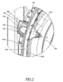
Figure 2 schematically shows cross-sectional view of an enlarged portion of the laundry machine ofFigure 1 , with a lighting system according an embodiment of the present invention; and -
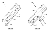
Figure 3A and Figure 3B schematically show an isometric view and an isometric exploded view, respectively, of a lifter according to an embodiment of the present invention. - Considering
Figure 1 andFigure 2 together, there are shown a cross-sectional and enlarged side views, respectively, of alaundry machine 100 according to an embodiment of the present invention. - The
laundry machine 100 is a machine for treating laundry (such has a laundry washing machine, a laundry washing/drying machine, a laundry drying machine etc.) of the top-loading type. Anyway, it should be apparent from the following description that also laundry machines of the front-loading type may also benefit from the solution according to the present invention. - In the example at issue, the
laundry machine 100 comprises a substantially parallelepiped-shaped casing 105 that, preferably, although not necessarily, encloses a substantially cylindrical-shaped tub 110 (it is underlined that the tub is advantageously provided in the case of a washing machine or a washing/drying machine, while the tub is not provided in case of a drying machine), wherein the laundry is treated, along with any other component of thelaundry machine 100 necessary for the operation (e.g., hydraulic, electronic and electromechanical apparatuses well known in the art and, therefore, not herein described for sake of conciseness). - With reference to enclosed
Figures 1 and2 , which represent the case of a top-loading washing machine, which therefore comprises a tub, thetub 110 is preferably fixed to a frame 115 (which substantially supports thecasing 105 and any other component comprised in the laundry machine 100), preferably by supporting elastic coils (one of which visible inFigure 1 , therein identified with the numeral 120), and shock (and vibration) absorber elements, such as two shock absorbers 125 (which absorb jolts of the tub during operation). - Furthermore, the
tub 110 houses a substantially cylindrical-shaped rotatingdrum 130, which, in operation, rotates about an axis A in order to tumble the laundry to be washed. Preferably, although not necessarily, one or more baffles orlifters drum wall 130a (parallel to a drum rotation axis A) in the inside of thedrum 130 for enhancing the tumbling action on laundry performed in operation by the same. - Conversely, in some laundry machines (for example, in dryer-type laundry machines), no tub is provided and the drum may advantageously be enclosed by the casing of the laundry machine; for example, in the case of a drying machine, the drum is preferably rotatably supported by a number of wheels provided in the base of the machine, inside the casing.
- In the example of
Figures 1 and2 , in order to allow a user to access thetub 110, anopening 140 is advantageously provided on the top of thewashing machine 100. The opening 140 is closable by a lid (removed in theFigure 1 ), which is preferably, although not necessarily, hingeably connected to thecasing 105 by means of a hinge (not shown in the figure). The lid is adapted to pivot from a closed position - wherein the lid closes the opening 140, impeding the access to the tub 110 - to an open position - wherein the lid is pivoted to an angle, preferably, equal to, or greater than, 90° with respect to the closed position, allowing the access to thetub 110. - Similarly, in order to allow a user to access the inside of the drum 130 (for loading/unloading the laundry), a drum opening is provided in the
drum wall 130a and adoor 145 is provided for closing the same during operation. Preferably, although not limitatively, thedoor 145 comprises afirst door leaf 145a and asecond door leaf 145b. - In the example illustrated in the enclosed figures, the
first door leaf 145a is advantageously hinged to thedrum 130 by afirst leaf hinge 150a, while thesecond door leaf 145b is hinged to thedrum 130 by asecond leaf hinge 150b. Preferably, in a closed position, interlocking elements (not shown in the figure) block the first and the second door leaves 145a and 145b to one another, thus impeding any unwanted (and harmful) opening of thedoor 145 during operation (i.e., when the drum rotates). - Clearly, in a further embodiment, not illustrated, the door may comprise a single door leaf; the following description refers to a door comprising two door leaves, but it can as well be applied to a door comprising a single door leaf (for example when, in the following, reference is made to the "first door leaf', it can be read also as "single door leaf' in case the door comprises only a single door leaf).
- In order to have the
door 145 in an open position (shown in theFigure 1 ), thelaundry machine 100, at the end of the operation, preferably aligns thedoor 145 with the opening 140 - alternatively or in addition, the user may align thedoor 145 with the opening 140 manually -; then the interlocking elements have to be unlocked, and the first and second door leaves 140a and 140b are preferably automatically rotated (preferably by elastic devices provided preferably in their hinges) until they abuts against - or reach a predetermined minimum distance from - abellow 155 connecting thetub 110 to the border of the opening 140, or, if the bellows is not provided, abuts directly against the border of the opening 140. - Having the machine lid (not illustrated in enclosed drawings) and the
drum door 145 both in the open position, the inside of thedrum 130 is accessible (through the drum opening) by the user for loading/unloading the laundry stored therein. - In addition, preferably, although not limitatively, a
user interface 160, for the selection of laundry treatment parameters (e.g., a temperature of a treatment fluid, a maximum rotation speed of thedrum 130, etc.), is provided, preferably on the top of thecasing 105. - In the laundry machine according to the present invention, a lighting system is provided for enlightening the inside of the drum.
- Preferably, in the solution according to the present invention, the lighting system comprises at least a light-emitting
element 165 provided on a stationary portion of the machine (i.e., any suitable part of the laundry machine for supporting the light-emitting element that does not rotates with the drum in operation; e.g., the tub, the casing the frame etc.), adapted to enlighten the inside of the drum. Advantageously, the light-emittingelement 165 is arranged in the stationary portion of the machine in such a way that a light-radiation emitted by such a light-emittingelement 165 reaches thedrum 130, directly, or via a light permeable and/or conductive element, for example a light-guide, not illustrated. - Moreover, a light-permeable portion (e.g., an
aperture 202 in the drum wall, or a transparent insert fixed in any suitable manner - e.g. by over-molding - on thedrum wall 130a or constructed in a single piece with the same) is provided in thedrum wall 130a, which light-permeable portion is arranged in such a way that a light radiation emitted by the light-emittingelement 165 and reaching thedrum wall 130a can enter thedrum 130 by the light-permeable portion, thus allowing a thoroughly enlightenment of the inside of thedrum 130, - In an advantageous embodiment the light-permeable portion of the
drum wall 130a and thelight emitting element 165 are arranged in such a way that when thedrum 130 is in a predetermined angular position (for example, in the case of a top-loading washing machine, is in the position allowing the opening of the door 145) thelight emitting element 165 faces and is aligned with the light-permeable portion of thedrum wall 130a, so that light enters thedrum 130 and illuminates the inside of the latter. Advantageously, a cover element may be provided over the light permeable portion of thedrum wall 130a, such cover element preferably comprising a transparent element for allowing the light radiation to enter inside thedrum 130. - In the example at issue, a light-emitting
element 165 may advantageously be provided on awall 110a of thetub 110. Conversely, in laundry machine of the dryer type a light-emittingelement 165 may be provided on an internal surface of the casing, on the frame of the laundry machine or on an electronic board comprised in the laundry machine (e.g., the electronic board comprising an electronic control unit of the laundry machine), and positioned/arranged in such a way that a light radiation emitted by the light-emittingelement 165 is able to enter thedrum 130 via such the light-permeable portion of thewall 130a of the latter. - As already mentioned, a light-permeable portion, such as an
aperture 202 is preferably provided on thedrum wall 130a. It should be noted that the light-permeable portion may advantageously be formed by a glass or a transparent polymer insert fixed in thedrum wall 130a in any suitable manner, or monolithically formed with the same (e.g. by over-molding); for example, in the case of a drying machine, the light-permeable portion may advantageously be monolithically formed with the drum wall, thus maintaining the inside of the drum sealed from the rest of the laundry machine. - In the advantageous embodiment illustrated in enclosed figures, at a predetermined position of the drum 130 (as will be described in the following), an axial alignment (i.e., both the light-emitting
element 165 and the light-permeable portion - e.g. the aperture 202 - share a same symmetry axis B) between the light-emittingelement 165 and the light-permeable portion - e.g. the aperture 202 - is possible (as will be described in greater detail in the following), since thetub wall 110a and thedrum wall 130a are parallel one another. - The light-emitting
element 165 is preferably mounted in aholder 205, for example a recess in the tub wall. Advantageously, the light-emittingelement 165 may comprise anysuitable lighting device 210, such as an incandescent light lamp, a fluorescent light lamp, a discharge light lamp or a solid-state lighting device (e.g., a LED - Light Emitting Diode). It should be noted that thelightning device 210 might comprise more than just one of the lighting devices listed above (e.g., thelightning device 210 may comprise a plurality of LEDs in a strip or a ring arrangement) in order to obtain a desired illumination intensity (i.e., able to grant a satisfactory enlightenment of the drum 130). - Similarly, in laundry machines without the tub, the light-emitting element may be enclosed in a box-like holder affixed, for example, to a casing or a frame portion of the laundry machine.
- The
lightning device 210 may advantageously be supplied with electric power in any known way; for example, thelightning device 210 may be supplied by a power circuit comprised in thelaundry machine 100, a selective connection with the mains or a battery arrangement (not shown in the figures). - It is underlined that, in the present application, expression "light-emitting element" has not to be interpreted only as a lamp or a similar "light-generating" device, but it refers to any device adapted to emit light radiation, for example the edge of an optical fiber, or of a light-guide (e.g., the free edge of a cylinder made of transparent plastics or glass). For example, such device may be adapted to guide light radiation - generated by a lightning device placed elsewhere in the laundry machine - towards the drum.
- Advantageously, a
light focuser 215 may be coupled with the light-emittingelement 165, designed to focus a light radiation generated by thelightning device 210 preferably towards thedrum wall 130a. For example, thelight focuser 215 may have a shape of a truncated elliptic paraboloid with the light-emittingdevice 165 placed at a truncated opened end and with the opposite opened end facing thedrum 130. - Preferably, although not necessarily, a
cap 220 made of a transparent material, may be provided for closing theholder recess 205. In this way, the light-emittingelement 165 may be advantageously sealed in theholder 205, thus, protected from treating liquids and/or moisture comprised in the tub 110 (at least during the operation of the laundry machine 100). - The holder 205 - and, therefore, the light-emitting element 165 - may advantageously be provided in such a way to prevent a user (looking inside the drum 130) from being directly hit by the light radiation emitted by the light-emitting
element 165, thus preventing glare and dazzling effects. For example, the light-emittingelement 165 may be provided in a top portion of thetub wall 110a (thus, also the probability of the light radiation resulting hindered by laundry inside the tub is substantially nullified). - The light-permeable portion, - e.g. the
aperture 202, in thedrum wall 130a may have any suitable shape (i.e., ranging from rectangular to circular) and, preferably, has a size adapted to let pass the whole light radiation emitted by the light-emittingelement 165 into thedrum 130. - A cover element, such as the
lifter 135b may be advantageously mounted on thedrum wall 130a (facing the inside of the drum 130) in correspondence of the light-permeable portion (e.g., the aperture 202) provided in thedrum wall 130a. - The
lifter 135b may be mounted in any know way, such as by means of screws, glue or a snap-fit arrangement. It should be noted that, thelifter 135b, being mounted over the light-permeable portion (e.g., the aperture 202), prevents laundry in the drum from obstructing such the light-permeable portion (e.g., the aperture 202), and/or if the light-permeable portion comprises theaperture 202, also prevents laundry form falling in thetub 110 via the aperture 202 (possibly, provoking malfunctions of thelaundry machine 100 in operation and/or damaging the laundry itself). - Considering now
Figure 3A and Figure 3B , there are schematically shown an isometric view and an isometric exploded view, respectively, of thelifter 135b according to an embodiment of the present invention. - The
lifter 135b advantageously comprises a hollowmain body 305 being substantially triangular prism-shaped with an opened base surface. In addition, the lifter comprises a transparent portion, such as atransparent element 310 adapted to be engaged with themain body 305. For example, the engagement between thetransparent element 310 and themain body 305 may be provided by a snap-fit arrangement 315. - The
main body 305 and thetransparent element 310 may advantageously be made of any suitable material, such as a polymer for the former and a transparent polymer for the latter. - Preferably, although not limitatively, the
transparent element 310 may be provided on atop edge portion 320 of themain body 305 opposed to anopen base surface 325 thereof, in order to transmit the light radiation (incoming from the light-emittingelement 165, as will be described in following) through the light-permeable portion (e.g., the aperture 202) into thedrum 130. - Advantageously, the
transparent element 310 may range in length, from a minimum extension - allowing the transmission of light radiation with a sufficient intensity inside the drum 130 -, to a maximum extension, substantially equal to a length of the top edge portion 320 - for the transmission of light radiation with the highest intensity achievable (in this embodiment of the present invention). - Advantageously, the
transparent element 310 may be shaped with a curvature adapted to direct the light radiation towards a central portion (corresponding to the rotation axis A) inside thedrum 130 in order to enlightening the same with a high intensity. This central portion inside thedrum 130 results to be preeminently used by the user during the laundry loading/unloading operations; thus, proper enlightenment of such central portion inside thedrum 130 is crucial for the user. - Alternatively, the
transparent element 310 may be shaped with a curvature adapted to uniformly diffuse the light radiation (i.e., diffusing the light radiation substantially in an isotropic manner) in the inside of thedrum 130. In this way, the inside of thedrum 130 results substantially completely and evenly enlightened. - In a further embodiment (not shown) according to the present invention, the transparent element may be formed integral (e.g. by over-molding or co-molding) with the lifter.
- In other embodiments (not shown) according to the present invention, the lifter may be completely made of a transparent material, thus being adapted to transmit the light radiation with any of its parts. In this case, the lifter advantageously comprises only a transparent main body, itself acting as the transparent element previously described.
- Having described the structure of the
laundry machine 100, the operation of the lightning system according to an embodiment of the present invention will now be described, referring to all the accompanying figures together. - Preferably, although not necessarily, the light-emitting
element 165 may be forced to emit a light radiation only when the laundry treatment is not in action (i.e., when the drum is not rotating). Even more preferably, the light-emittingelement 165 may be forced to emit the light radiation only when thedrum 130 is in a predetermined position (e.g., by means of a electromechanical switch, not shown, that closes when thedrum 130 is rotated in the predetermined position); for example, when thedrum 130 is in a position allowing thedrum door 145 to be opened (i.e., with both the door leaves 145a and 145b in the open position). - In some embodiments, the lightning device may, advantageously, be adapted to emit a light radiation automatically when the lid (or a door in front-loading type laundry machines) is in the open position.
- Alternatively or in addition, a pushbutton (not shown) may be provided in the
user interface 160 allowing a user to selectively force the light radiation emission by the light-emittingelement 165. - Advantageously, the
lifter 135b is mounted on the drum 130 (covering the light-permeable portion -e.g. the drum aperture 202-) in such a way that, when thedrum 130 is in the predetermined position, also thelifter 135b results axially aligned with the light-emitting element 165 (as shown inFigure 1 andFigure 2 ). In this way, by passing trough the light-permeable portion (e.g. the aperture 202) in thedrum wall 130a and trough thetransparent element 310 of thelifter 135b the light radiation emitted by thelight emitting source 165 is able to reach into thedrum 130 with a sufficient intensity in order to thoroughly enlighten the same. - It should be noted that the
lifter 135b, along with transmitting the light radiation into thedrum 130 thanks to thetransparent element 310, also enhances the tumbling action, as do the lifters known in the art during thelaundry machine 100 operation. - In other embodiments according to the present invention, the
lifter 135b may be omitted, and a transparent panel (acting as light-permeable element) may be provided in a single-piece construction (single-body) with the drum. In this way, the light radiation can pass through such transparent panel, while laundry in the drum is prevented from falling in the tub (possibly, provoking malfunctions in laundry machine operation and/or damaging the laundry itself). Similarly, in laundry machines with no tub (such as dryer-type laundry machine), the transparent panel grants a proper sealing of the inside of the drum from the rest of the laundry machine (thus preventing any unwanted moisture and/or steam - present in the drum during operation - dispersion inside the casing and/or in the environment). - The lightning system according to the present invention is able to provide a satisfactory enlightenment of the inside of the drum, thus facilitating inspection thereof and laundry loading/unloading tasks. At the same time, the lightning system according to the present invention overcomes the above-discussed drawbacks with a robust and cost-effective solution.
Claims (12)
- A laundry machine (100) for treating laundry items, comprising:an outer casing (105), which rotatably houses a drum (130) for accommodating the items to be treated, anda lighting system (165,310) for enlightening the inside of the drum (130), the lighting system including a light-emitting element (165) provided on a stationary portion (110a) of the laundry machine (100), for emitting a light radiation towards a drum wall (130a),
characterized in thatthe drum comprises at least one light-permeable portion (202) formed in the drum wall (130a), andthe lightning system further comprises a transparent element (310) mounted inside the drum (130) in correspondence of said light-permeable portion (202), adapted to allow the light radiation emitted by said light-emitting element (165), and crossing said light-permeable portion (202), to reach the inside of the drum (130). - The laundry machine (100) according to claim 1, wherein the drum (130) is adapted to be rotated in a predetermined position in which said light-permeable portion (202) and said transparent element (310) are axially-aligned with the light-emitting element (165).
- The laundry machine (100) according to claim 1 or 2, wherein the transparent element (310) is adapted to direct the light radiation towards a central portion inside the drum (130).
- The laundry machine (100) according to claim 1 or 2, wherein the transparent element (310) is adapted to uniformly diffuse the light radiation.
- The laundry machine (100) according to any one of the preceding claims, further comprising a cover element (135b) having a hollow main body (305) and comprising said transparent element (310), said cover element (135b) being mounted on the drum wall (130a) over said light-permeable portion (202).
- The laundry machine (100) according to claim 5, wherein the transparent element (310) is provided on a top edge portion (320) of the hollow main body (305).
- The laundry machine (100) according to claim 5 or 6, wherein the hollow main body (305) comprises an open base surface (325) opposite to the top edge portion (320), said open base surface (325) encompassing the light-permeable portion (202).
- The laundry machine (100) according to any claim 5-7, wherein the transparent element (310) engages the hollow main body (305) of the cover element (135b) by means of a snap-fit engagement (315).
- The laundry machine (100) according to any claim 5-8, wherein the cover element (135b) is a lifter (135b) adapted to improve the tumbling of items during the laundry machine (100) operation.
- The laundry machine (100) according to any one of the preceding claims, further comprising a holder (205) in the stationary portion (110a) of the laundry machine (100) for housing the light-emitting element (165).
- The laundry machine (100) according to any one of the preceding claims, further comprising a light focuser (215), coupled with the light-emitting element (165) adapted to focus the light radiation generated by said light-emitting element (165) towards the drum wall (130a).
- The laundry machine (100) according to claim 10 or 11, further comprising a transparent cap (220) adapted to close the holder (205), for sealing the light-emitting element (165) away from liquids and/or moisture comprised in the stationary portion (110a) of the laundry machine (100).
Priority Applications (1)
| Application Number | Priority Date | Filing Date | Title |
|---|---|---|---|
| EP11193993.0A EP2604741B1 (en) | 2011-12-16 | 2011-12-16 | Lighting apparatus for laundry machines |
Applications Claiming Priority (1)
| Application Number | Priority Date | Filing Date | Title |
|---|---|---|---|
| EP11193993.0A EP2604741B1 (en) | 2011-12-16 | 2011-12-16 | Lighting apparatus for laundry machines |
Publications (2)
| Publication Number | Publication Date |
|---|---|
| EP2604741A1 true EP2604741A1 (en) | 2013-06-19 |
| EP2604741B1 EP2604741B1 (en) | 2015-10-14 |
Family
ID=45440208
Family Applications (1)
| Application Number | Title | Priority Date | Filing Date |
|---|---|---|---|
| EP11193993.0A Active EP2604741B1 (en) | 2011-12-16 | 2011-12-16 | Lighting apparatus for laundry machines |
Country Status (1)
| Country | Link |
|---|---|
| EP (1) | EP2604741B1 (en) |
Families Citing this family (3)
| Publication number | Priority date | Publication date | Assignee | Title |
|---|---|---|---|---|
| US11377772B2 (en) | 2019-05-23 | 2022-07-05 | Whirlpool Corporation | Laundry appliance |
| US11761134B2 (en) | 2019-05-23 | 2023-09-19 | Whirlpool Corporation | Laundry appliance |
| US11851805B2 (en) | 2021-11-22 | 2023-12-26 | Whirlpool Corporation | Deflector assembly for laundry appliance |
Citations (5)
| Publication number | Priority date | Publication date | Assignee | Title |
|---|---|---|---|---|
| DE1051234B (en) * | 1955-02-28 | 1959-02-26 | Siemens Elektrogeraete Gmbh | Drum washing machine |
| DE4026547A1 (en) | 1990-08-22 | 1992-03-19 | Bosch Siemens Hausgeraete | WASHING MACHINE |
| DE10316377B3 (en) * | 2003-04-10 | 2004-09-23 | Insta Elektro Gmbh | Lighting system for drum of washing machine has lamp fastened to machine housing on axis of drum and shining through transparent rod with convex end projecting into interior of drum |
| JP2005253786A (en) * | 2004-03-12 | 2005-09-22 | Sanyo Electric Co Ltd | Washing machine |
| EP1598473A1 (en) * | 2004-05-20 | 2005-11-23 | Lg Electronics Inc. | Dryer and lamp cover mounting structure for dryer |
-
2011
- 2011-12-16 EP EP11193993.0A patent/EP2604741B1/en active Active
Patent Citations (5)
| Publication number | Priority date | Publication date | Assignee | Title |
|---|---|---|---|---|
| DE1051234B (en) * | 1955-02-28 | 1959-02-26 | Siemens Elektrogeraete Gmbh | Drum washing machine |
| DE4026547A1 (en) | 1990-08-22 | 1992-03-19 | Bosch Siemens Hausgeraete | WASHING MACHINE |
| DE10316377B3 (en) * | 2003-04-10 | 2004-09-23 | Insta Elektro Gmbh | Lighting system for drum of washing machine has lamp fastened to machine housing on axis of drum and shining through transparent rod with convex end projecting into interior of drum |
| JP2005253786A (en) * | 2004-03-12 | 2005-09-22 | Sanyo Electric Co Ltd | Washing machine |
| EP1598473A1 (en) * | 2004-05-20 | 2005-11-23 | Lg Electronics Inc. | Dryer and lamp cover mounting structure for dryer |
Also Published As
| Publication number | Publication date |
|---|---|
| EP2604741B1 (en) | 2015-10-14 |
Similar Documents
| Publication | Publication Date | Title |
|---|---|---|
| US9150995B2 (en) | Laundry machine with lighting apparatus for drum lighting | |
| US10604879B2 (en) | Laundry treatment apparatus | |
| ES2348908T3 (en) | CLOTHING TREATMENT MACHINE WITH A LIGHTING DEVICE. | |
| EP2604741B1 (en) | Lighting apparatus for laundry machines | |
| KR20040046987A (en) | A controller of washing machine | |
| CN101397742A (en) | Drum-type washer | |
| KR20180136140A (en) | Wall mounted drum type washing machine | |
| RU2009120514A (en) | WASHING AND DRYING MACHINE | |
| KR101176136B1 (en) | Washing machine and LED assembly of the same and Control method of the same | |
| CN107208345B (en) | Washing machine | |
| EP2604734A1 (en) | Lighting apparatus for laundry machines | |
| CN108866915A (en) | Device for clothing processing | |
| CN117980555A (en) | Household appliance having an opening and closing front door assembly | |
| JP2006197963A (en) | Drum type washer / dryer | |
| CN109402989B (en) | Clothes dryer | |
| CN114616372A (en) | Front loading washing machine with electric lamp body | |
| KR100955907B1 (en) | Lighting device for drum washing machine | |
| KR102578642B1 (en) | Laundry treatment apparatus | |
| KR101221887B1 (en) | drum tilt type washing machine | |
| CN110241556B (en) | Washing care appliance with external luminous element | |
| KR20050086200A (en) | Control apparatus of washing machine | |
| KR20200114504A (en) | Laundry treating apparatus | |
| KR101295274B1 (en) | drum-type washer | |
| KR20250089328A (en) | Filter module, filter apparatus, and clothes treating apparatus | |
| KR101203853B1 (en) | structure for assembling of lamp-device in drum-type washer |
Legal Events
| Date | Code | Title | Description |
|---|---|---|---|
| PUAI | Public reference made under article 153(3) epc to a published international application that has entered the european phase |
Free format text: ORIGINAL CODE: 0009012 |
|
| AK | Designated contracting states |
Kind code of ref document: A1 Designated state(s): AL AT BE BG CH CY CZ DE DK EE ES FI FR GB GR HR HU IE IS IT LI LT LU LV MC MK MT NL NO PL PT RO RS SE SI SK SM TR |
|
| AX | Request for extension of the european patent |
Extension state: BA ME |
|
| 17P | Request for examination filed |
Effective date: 20131216 |
|
| RBV | Designated contracting states (corrected) |
Designated state(s): AL AT BE BG CH CY CZ DE DK EE ES FI FR GB GR HR HU IE IS IT LI LT LU LV MC MK MT NL NO PL PT RO RS SE SI SK SM TR |
|
| 17Q | First examination report despatched |
Effective date: 20140403 |
|
| GRAP | Despatch of communication of intention to grant a patent |
Free format text: ORIGINAL CODE: EPIDOSNIGR1 |
|
| INTG | Intention to grant announced |
Effective date: 20150629 |
|
| GRAS | Grant fee paid |
Free format text: ORIGINAL CODE: EPIDOSNIGR3 |
|
| GRAA | (expected) grant |
Free format text: ORIGINAL CODE: 0009210 |
|
| AK | Designated contracting states |
Kind code of ref document: B1 Designated state(s): AL AT BE BG CH CY CZ DE DK EE ES FI FR GB GR HR HU IE IS IT LI LT LU LV MC MK MT NL NO PL PT RO RS SE SI SK SM TR |
|
| REG | Reference to a national code |
Ref country code: GB Ref legal event code: FG4D |
|
| REG | Reference to a national code |
Ref country code: AT Ref legal event code: REF Ref document number: 755153 Country of ref document: AT Kind code of ref document: T Effective date: 20151015 Ref country code: CH Ref legal event code: EP |
|
| REG | Reference to a national code |
Ref country code: IE Ref legal event code: FG4D |
|
| REG | Reference to a national code |
Ref country code: DE Ref legal event code: R096 Ref document number: 602011020547 Country of ref document: DE |
|
| REG | Reference to a national code |
Ref country code: FR Ref legal event code: PLFP Year of fee payment: 5 |
|
| REG | Reference to a national code |
Ref country code: NL Ref legal event code: MP Effective date: 20151014 |
|
| REG | Reference to a national code |
Ref country code: LT Ref legal event code: MG4D |
|
| REG | Reference to a national code |
Ref country code: AT Ref legal event code: MK05 Ref document number: 755153 Country of ref document: AT Kind code of ref document: T Effective date: 20151014 |
|
| PG25 | Lapsed in a contracting state [announced via postgrant information from national office to epo] |
Ref country code: HR Free format text: LAPSE BECAUSE OF FAILURE TO SUBMIT A TRANSLATION OF THE DESCRIPTION OR TO PAY THE FEE WITHIN THE PRESCRIBED TIME-LIMIT Effective date: 20151014 Ref country code: IS Free format text: LAPSE BECAUSE OF FAILURE TO SUBMIT A TRANSLATION OF THE DESCRIPTION OR TO PAY THE FEE WITHIN THE PRESCRIBED TIME-LIMIT Effective date: 20160214 Ref country code: LT Free format text: LAPSE BECAUSE OF FAILURE TO SUBMIT A TRANSLATION OF THE DESCRIPTION OR TO PAY THE FEE WITHIN THE PRESCRIBED TIME-LIMIT Effective date: 20151014 Ref country code: NL Free format text: LAPSE BECAUSE OF FAILURE TO SUBMIT A TRANSLATION OF THE DESCRIPTION OR TO PAY THE FEE WITHIN THE PRESCRIBED TIME-LIMIT Effective date: 20151014 Ref country code: ES Free format text: LAPSE BECAUSE OF FAILURE TO SUBMIT A TRANSLATION OF THE DESCRIPTION OR TO PAY THE FEE WITHIN THE PRESCRIBED TIME-LIMIT Effective date: 20151014 Ref country code: NO Free format text: LAPSE BECAUSE OF FAILURE TO SUBMIT A TRANSLATION OF THE DESCRIPTION OR TO PAY THE FEE WITHIN THE PRESCRIBED TIME-LIMIT Effective date: 20160114 |
|
| PG25 | Lapsed in a contracting state [announced via postgrant information from national office to epo] |
Ref country code: RS Free format text: LAPSE BECAUSE OF FAILURE TO SUBMIT A TRANSLATION OF THE DESCRIPTION OR TO PAY THE FEE WITHIN THE PRESCRIBED TIME-LIMIT Effective date: 20151014 Ref country code: AT Free format text: LAPSE BECAUSE OF FAILURE TO SUBMIT A TRANSLATION OF THE DESCRIPTION OR TO PAY THE FEE WITHIN THE PRESCRIBED TIME-LIMIT Effective date: 20151014 Ref country code: GR Free format text: LAPSE BECAUSE OF FAILURE TO SUBMIT A TRANSLATION OF THE DESCRIPTION OR TO PAY THE FEE WITHIN THE PRESCRIBED TIME-LIMIT Effective date: 20160115 Ref country code: LV Free format text: LAPSE BECAUSE OF FAILURE TO SUBMIT A TRANSLATION OF THE DESCRIPTION OR TO PAY THE FEE WITHIN THE PRESCRIBED TIME-LIMIT Effective date: 20151014 Ref country code: PT Free format text: LAPSE BECAUSE OF FAILURE TO SUBMIT A TRANSLATION OF THE DESCRIPTION OR TO PAY THE FEE WITHIN THE PRESCRIBED TIME-LIMIT Effective date: 20160215 Ref country code: PL Free format text: LAPSE BECAUSE OF FAILURE TO SUBMIT A TRANSLATION OF THE DESCRIPTION OR TO PAY THE FEE WITHIN THE PRESCRIBED TIME-LIMIT Effective date: 20151014 Ref country code: BE Free format text: LAPSE BECAUSE OF NON-PAYMENT OF DUE FEES Effective date: 20151231 Ref country code: SE Free format text: LAPSE BECAUSE OF FAILURE TO SUBMIT A TRANSLATION OF THE DESCRIPTION OR TO PAY THE FEE WITHIN THE PRESCRIBED TIME-LIMIT Effective date: 20151014 Ref country code: FI Free format text: LAPSE BECAUSE OF FAILURE TO SUBMIT A TRANSLATION OF THE DESCRIPTION OR TO PAY THE FEE WITHIN THE PRESCRIBED TIME-LIMIT Effective date: 20151014 |
|
| REG | Reference to a national code |
Ref country code: DE Ref legal event code: R097 Ref document number: 602011020547 Country of ref document: DE |
|
| PG25 | Lapsed in a contracting state [announced via postgrant information from national office to epo] |
Ref country code: CZ Free format text: LAPSE BECAUSE OF FAILURE TO SUBMIT A TRANSLATION OF THE DESCRIPTION OR TO PAY THE FEE WITHIN THE PRESCRIBED TIME-LIMIT Effective date: 20151014 Ref country code: MC Free format text: LAPSE BECAUSE OF FAILURE TO SUBMIT A TRANSLATION OF THE DESCRIPTION OR TO PAY THE FEE WITHIN THE PRESCRIBED TIME-LIMIT Effective date: 20151014 Ref country code: LU Free format text: LAPSE BECAUSE OF FAILURE TO SUBMIT A TRANSLATION OF THE DESCRIPTION OR TO PAY THE FEE WITHIN THE PRESCRIBED TIME-LIMIT Effective date: 20151216 |
|
| REG | Reference to a national code |
Ref country code: CH Ref legal event code: PL |
|
| PLBE | No opposition filed within time limit |
Free format text: ORIGINAL CODE: 0009261 |
|
| STAA | Information on the status of an ep patent application or granted ep patent |
Free format text: STATUS: NO OPPOSITION FILED WITHIN TIME LIMIT |
|
| PG25 | Lapsed in a contracting state [announced via postgrant information from national office to epo] |
Ref country code: RO Free format text: LAPSE BECAUSE OF FAILURE TO SUBMIT A TRANSLATION OF THE DESCRIPTION OR TO PAY THE FEE WITHIN THE PRESCRIBED TIME-LIMIT Effective date: 20151014 Ref country code: EE Free format text: LAPSE BECAUSE OF FAILURE TO SUBMIT A TRANSLATION OF THE DESCRIPTION OR TO PAY THE FEE WITHIN THE PRESCRIBED TIME-LIMIT Effective date: 20151014 Ref country code: DK Free format text: LAPSE BECAUSE OF FAILURE TO SUBMIT A TRANSLATION OF THE DESCRIPTION OR TO PAY THE FEE WITHIN THE PRESCRIBED TIME-LIMIT Effective date: 20151014 Ref country code: SM Free format text: LAPSE BECAUSE OF FAILURE TO SUBMIT A TRANSLATION OF THE DESCRIPTION OR TO PAY THE FEE WITHIN THE PRESCRIBED TIME-LIMIT Effective date: 20151014 Ref country code: SK Free format text: LAPSE BECAUSE OF FAILURE TO SUBMIT A TRANSLATION OF THE DESCRIPTION OR TO PAY THE FEE WITHIN THE PRESCRIBED TIME-LIMIT Effective date: 20151014 |
|
| 26N | No opposition filed |
Effective date: 20160715 |
|
| REG | Reference to a national code |
Ref country code: IE Ref legal event code: MM4A |
|
| PG25 | Lapsed in a contracting state [announced via postgrant information from national office to epo] |
Ref country code: CH Free format text: LAPSE BECAUSE OF NON-PAYMENT OF DUE FEES Effective date: 20151231 Ref country code: LI Free format text: LAPSE BECAUSE OF NON-PAYMENT OF DUE FEES Effective date: 20151231 Ref country code: IE Free format text: LAPSE BECAUSE OF NON-PAYMENT OF DUE FEES Effective date: 20151216 |
|
| PG25 | Lapsed in a contracting state [announced via postgrant information from national office to epo] |
Ref country code: SI Free format text: LAPSE BECAUSE OF FAILURE TO SUBMIT A TRANSLATION OF THE DESCRIPTION OR TO PAY THE FEE WITHIN THE PRESCRIBED TIME-LIMIT Effective date: 20151014 |
|
| REG | Reference to a national code |
Ref country code: FR Ref legal event code: PLFP Year of fee payment: 6 |
|
| PG25 | Lapsed in a contracting state [announced via postgrant information from national office to epo] |
Ref country code: BE Free format text: LAPSE BECAUSE OF FAILURE TO SUBMIT A TRANSLATION OF THE DESCRIPTION OR TO PAY THE FEE WITHIN THE PRESCRIBED TIME-LIMIT Effective date: 20151014 |
|
| PGFP | Annual fee paid to national office [announced via postgrant information from national office to epo] |
Ref country code: GB Payment date: 20161222 Year of fee payment: 6 |
|
| PGFP | Annual fee paid to national office [announced via postgrant information from national office to epo] |
Ref country code: FR Payment date: 20161222 Year of fee payment: 6 |
|
| PG25 | Lapsed in a contracting state [announced via postgrant information from national office to epo] |
Ref country code: HU Free format text: LAPSE BECAUSE OF FAILURE TO SUBMIT A TRANSLATION OF THE DESCRIPTION OR TO PAY THE FEE WITHIN THE PRESCRIBED TIME-LIMIT; INVALID AB INITIO Effective date: 20111216 Ref country code: BG Free format text: LAPSE BECAUSE OF FAILURE TO SUBMIT A TRANSLATION OF THE DESCRIPTION OR TO PAY THE FEE WITHIN THE PRESCRIBED TIME-LIMIT Effective date: 20151014 |
|
| PG25 | Lapsed in a contracting state [announced via postgrant information from national office to epo] |
Ref country code: CY Free format text: LAPSE BECAUSE OF FAILURE TO SUBMIT A TRANSLATION OF THE DESCRIPTION OR TO PAY THE FEE WITHIN THE PRESCRIBED TIME-LIMIT Effective date: 20151014 |
|
| PG25 | Lapsed in a contracting state [announced via postgrant information from national office to epo] |
Ref country code: MT Free format text: LAPSE BECAUSE OF FAILURE TO SUBMIT A TRANSLATION OF THE DESCRIPTION OR TO PAY THE FEE WITHIN THE PRESCRIBED TIME-LIMIT Effective date: 20151014 |
|
| PG25 | Lapsed in a contracting state [announced via postgrant information from national office to epo] |
Ref country code: MK Free format text: LAPSE BECAUSE OF FAILURE TO SUBMIT A TRANSLATION OF THE DESCRIPTION OR TO PAY THE FEE WITHIN THE PRESCRIBED TIME-LIMIT Effective date: 20151014 Ref country code: TR Free format text: LAPSE BECAUSE OF FAILURE TO SUBMIT A TRANSLATION OF THE DESCRIPTION OR TO PAY THE FEE WITHIN THE PRESCRIBED TIME-LIMIT Effective date: 20151014 |
|
| GBPC | Gb: european patent ceased through non-payment of renewal fee |
Effective date: 20171216 |
|
| REG | Reference to a national code |
Ref country code: FR Ref legal event code: ST Effective date: 20180831 |
|
| PG25 | Lapsed in a contracting state [announced via postgrant information from national office to epo] |
Ref country code: AL Free format text: LAPSE BECAUSE OF FAILURE TO SUBMIT A TRANSLATION OF THE DESCRIPTION OR TO PAY THE FEE WITHIN THE PRESCRIBED TIME-LIMIT Effective date: 20151014 Ref country code: FR Free format text: LAPSE BECAUSE OF NON-PAYMENT OF DUE FEES Effective date: 20180102 |
|
| PG25 | Lapsed in a contracting state [announced via postgrant information from national office to epo] |
Ref country code: GB Free format text: LAPSE BECAUSE OF NON-PAYMENT OF DUE FEES Effective date: 20171216 |
|
| P01 | Opt-out of the competence of the unified patent court (upc) registered |
Effective date: 20230625 |
|
| PGFP | Annual fee paid to national office [announced via postgrant information from national office to epo] |
Ref country code: IT Payment date: 20251218 Year of fee payment: 15 |
|
| PGFP | Annual fee paid to national office [announced via postgrant information from national office to epo] |
Ref country code: DE Payment date: 20251229 Year of fee payment: 15 |