EP2604353A1 - Wire drawing apparatus with roller units - Google Patents
Wire drawing apparatus with roller units Download PDFInfo
- Publication number
- EP2604353A1 EP2604353A1 EP12196664.2A EP12196664A EP2604353A1 EP 2604353 A1 EP2604353 A1 EP 2604353A1 EP 12196664 A EP12196664 A EP 12196664A EP 2604353 A1 EP2604353 A1 EP 2604353A1
- Authority
- EP
- European Patent Office
- Prior art keywords
- wire
- main body
- metal wire
- lubricant
- roller units
- Prior art date
- Legal status (The legal status is an assumption and is not a legal conclusion. Google has not performed a legal analysis and makes no representation as to the accuracy of the status listed.)
- Granted
Links
Images


Classifications
-
- B—PERFORMING OPERATIONS; TRANSPORTING
- B21—MECHANICAL METAL-WORKING WITHOUT ESSENTIALLY REMOVING MATERIAL; PUNCHING METAL
- B21C—MANUFACTURE OF METAL SHEETS, WIRE, RODS, TUBES, PROFILES OR LIKE SEMI-MANUFACTURED PRODUCTS OTHERWISE THAN BY ROLLING; AUXILIARY OPERATIONS USED IN CONNECTION WITH METAL-WORKING WITHOUT ESSENTIALLY REMOVING MATERIAL
- B21C3/00—Profiling tools for metal drawing; Combinations of dies and mandrels for metal drawing
- B21C3/02—Dies; Selection of material therefor; Cleaning thereof
- B21C3/08—Dies; Selection of material therefor; Cleaning thereof with section defined by rollers, balls, or the like
-
- B—PERFORMING OPERATIONS; TRANSPORTING
- B21—MECHANICAL METAL-WORKING WITHOUT ESSENTIALLY REMOVING MATERIAL; PUNCHING METAL
- B21C—MANUFACTURE OF METAL SHEETS, WIRE, RODS, TUBES, PROFILES OR LIKE SEMI-MANUFACTURED PRODUCTS OTHERWISE THAN BY ROLLING; AUXILIARY OPERATIONS USED IN CONNECTION WITH METAL-WORKING WITHOUT ESSENTIALLY REMOVING MATERIAL
- B21C3/00—Profiling tools for metal drawing; Combinations of dies and mandrels for metal drawing
- B21C3/02—Dies; Selection of material therefor; Cleaning thereof
- B21C3/12—Die holders; Rotating dies
- B21C3/14—Die holders combined with devices for guiding the drawing material or combined with devices for cooling, heating, or lubricating
Definitions
- the present invention relates to a wire drawing apparatus including a plurality of roller units and a lubricating unit.
- FIG. 1 shows a conventional wire drawing apparatus disclosed in R.O.C. patent publication M380174 .
- the wire drawing apparatus includes a main body 11, and a die 12 disposed on the main body 11.
- the main body 11 includes a lubricant storage 111 for storing lubricating powder
- the die 12 includes a tunnel 13.
- the tunnel 13 has an inlet 131 that decreases in diameter in the direction away from the lubricant storage 111, and an outlet 132 in spatial communication with the inlet 131.
- the surface of the metal wire (not shown in Figure 1 ) is first coated with the lubricating powder as the metal wire passes through the lubricant storage 111 before passing through the inlet 131 of the die 12. Since the diameter of the inlet 131 of the die 12 decreases gradually, the metal wire passing through the inlet 131 is pressed as it exits through the outlet 132, with the diameter of the metal wire reduced. Therefore, the objective of decreasing the diameter of the metal wire is achieved.
- the object of the present invention is to provide a wire drawing apparatus for drawing a metal wire that is capable of alleviating the abovementioned drawbacks of the prior art.
- the wire drawing apparatus is characterized by:
- the preferred embodiment of a wire drawing apparatus of the present invention includes a base 3, two wire pressing devices 4 disposed on the base 3, two lubricating units 5 respectively disposed on the wire pressing devices 4, and two guide units 6 respectively disposed on the wire pressing devices 4.
- Each pressing device 4 includes a main body 41 assembled with the base 3 and three roller units 42 assembled on the main body 41.
- the main body 41 has a hole 411 through which a metal wire 7 is extended, and the roller units 42 are assembled relative to the hole 411 in an equiangularly displaced manner for surrounding and applying compression forces on the metal wire 7.
- Each roller unit 42 includes an eccentric shaft 421 installed on the main body 41, a bearing 422 sleeved on the eccentric shaft 421, a roller body 423 installed on the bearing 422 for contacting the metal wire 7, and a plurality of leak-proofing members 424 sleeved on the eccentric shaft 421 and positioned in between the eccentric shaft 421 and the roller body 423.
- Each lubricating unit 5 includes a lubricant inlet 51 provided on the main body 41, a lubricant outlet 53 provided on the main body 41, and three passages 52 formed respectively in the roller units 42.
- the three passages 52 are in fluid communication with the lubricant inlet 51 and the lubricant outlet 53 (since all passages 52 have the same configuration, only one passage 52 is shown in Figure 3 ).
- Each passage 52 includes an inlet section 521 in fluid communication with the lubricant inlet 51 and disposed in the eccentric shaft 421, an outlet section 523 in fluid communication with the lubricant outlet 53 and disposed in the eccentric shaft 421, and a lubricating section 522 that is in fluid communication with the inlet section 521 and the outlet section 523 and that is formed through the bearing 422.
- Each guide unit 6 includes a base part 61 assembled to the main body 41 of the corresponding wire pressing device 4 and three guide wheels 62 that are disposed rotatably on the base part 61 and that provide a winding path for the metal wire 7.
- the guide unit 6 and the roller units 42 are disposed on opposite sides of the main body 41 of the corresponding wire pressing device 4, and the winding path provided by the guide wheels 62 is aligned with the hole 411 in the main body 41 of the corresponding wire pressing device 4.
- a driver unit (not shown in the Figure), by pulling the metal wire 7, enables the metal wire 7 to first go around and through the three guide wheels 62 of one of the guide units 6, and then passes through the hole 411 of the main body 41 of one of the wire pressing devices 4.
- the metal wire 7 is then surrounded and pressed by the roller bodies 423 of the roller units 42 of one of the wire pressing devices 4, causing the diameter of the metal wire 7 to be reduced.
- the metal wire 7 is then pressed again by the roller bodies 423 of the other one of the wire pressing devices 4, and exits through the hole 411 of the main body 41 of the other one of the wire pressing devices 4.
- the metal wire 7 that goes around and passes through the three guide wheels 62 of the other one of the guide units 6 is reduced to a smaller diameter.
- the metal wire 7 in this preferred embodiment is made of low carbon steel, and the diameter of which is reduced from 5.5mm to 1.0mm through the wire drawing process.
- the material and diameter of the metal wire 7 are not limited to such.
- a pump (not shown in the Figure) injects a lubricant into the lubricant inlet 51 of each lubricating unit 5 (see Figure 2 ), causing the lubricant to enter, in the direction as indicated by the arrow A in Figure 3 , the eccentric shaft 421 through the inlet section 521 of the corresponding passage 52.
- the lubricant then passes through the lubricating section 522 to cool the eccentric shaft 421 and the bearing 422 of the corresponding roller units 42.
- the lubricant exits the eccentric shaft 421 through the outlet section 523 of the corresponding passage 52 in the direction as indicated by the arrow B in Figure 3 and exits the wire pressing devices 4 through the lubricant outlets 53 of the lubricating units 5.
- the leak-proofing members 424 prevent lubricant from leaking through the eccentric shaft 421 and the roller body 423.
- the guide wheels 62 of the guide units 6 enable the metal wire 7 to stably enter and exit the holes 411 of the wire pressing devices 4 and to be stably press rolled by the roller units 42. Since the roller units 42 of the wire pressing devices 4 press roll the metal wire 7 to reduce diameter of the same, the friction produced is minimal and the application of lubricating powder onto the metal wire 7 is therefore not required. Also, since the roller press method covers a large surface area of the metal wire 7, the number of times of wire drawing required for achieving a desired diameter is reduced and therefore the speed of manufacturing is increased.
- the lubricant passes through the passages 52 of the lubricating units 5, it lubricates and extends the life span of the bearings 422.
- the lubricant also provides a cooling effect by drawing heat away from the roller units 42 when they are rolling, reducing the likelihood of deterioration of the material of the roller units 42.
Landscapes
- Engineering & Computer Science (AREA)
- Mechanical Engineering (AREA)
- Metal Extraction Processes (AREA)
- Metal Rolling (AREA)
Abstract
Description
- The present invention relates to a wire drawing apparatus including a plurality of roller units and a lubricating unit.
- Metal wire drawing is commonly achieved with a wire drawing apparatus having a die that decreases the diameter of the metal wire.
Figure 1 shows a conventional wire drawing apparatus disclosed in R.O.C. patent publicationM380174 main body 11, and a die 12 disposed on themain body 11. Themain body 11 includes alubricant storage 111 for storing lubricating powder, and the die 12 includes atunnel 13. Thetunnel 13 has aninlet 131 that decreases in diameter in the direction away from thelubricant storage 111, and anoutlet 132 in spatial communication with theinlet 131. The surface of the metal wire (not shown inFigure 1 ) is first coated with the lubricating powder as the metal wire passes through thelubricant storage 111 before passing through theinlet 131 of thedie 12. Since the diameter of theinlet 131 of thedie 12 decreases gradually, the metal wire passing through theinlet 131 is pressed as it exits through theoutlet 132, with the diameter of the metal wire reduced. Therefore, the objective of decreasing the diameter of the metal wire is achieved. - However, such wire drawing using the die 12 possesses the following drawbacks:
- 1. Quality of the metal wire drawn is unstable:
- Due to the large contact surface between the metal wire and the
die 12, when the metal wire passes through thedie 12, huge amount of friction and heat are produced. High temperature in thetunnel 13 after prolonged use causes thetunnel 13 to be worn and scratched, which causes the diameter of thetunnel 13 to increase, causing the quality of the wire drawn from the apparatus to be unstable.
- Due to the large contact surface between the metal wire and the
- 2.Hugh amount of electricity consumed:
- Due to the friction between the
die 12 and the metal wire, a motor (not shown inFigure 1 ) used for pulling the metal wire requires a huge amount of energy and therefore consumes a large amount of electricity, resulting in high manufacturing cost.
- Due to the friction between the
- 3.Slow production speed and frequent replacement of the die:
- In order to reduce the friction between the metal wire and the
die 12, the diameter of theinlet 131 of thedie 12 must decrease gradually in shape, and therefore the metal wire has to be drawn many times by passing throughmany dies 12 in order for the metal wire to be drawn to the required diameter. As mentioned hereinabove, thetunnel 13, after prolonged use, becomes worn and scratched, and the production line has to be stopped in order to replace the die 12, wasting unnecessary manpower and slowing production speed. Commonly, replacement of the die 12 is required for every 10 tons of metal wires. - 4.pollution to the environment:
- In order to decrease the friction between the metal wire and the
die 12, the metal wire is first cleaned using hydrochloric acid or sulphuric acid and the lubricating powder is then applied before passing the metal wire through thedie 12 for wire drawing. However, using a large amount of lubricating powder and acidic cleaners raises manufacturing costs. Furthermore, the particles of the lubricating powder are harmful to the human respiratory system, and also can cause damage to electrical equipments. The acidic cleaners used in cleaning the metal wires also cause environmental pollution.
- In order to decrease the friction between the metal wire and the
- In order to reduce the friction between the metal wire and the
- The object of the present invention is to provide a wire drawing apparatus for drawing a metal wire that is capable of alleviating the abovementioned drawbacks of the prior art.
- According to the present invention, the wire drawing apparatus is characterized by:
- a wire pressing device including a main body and a plurality of roller units assembled on the main body, the main body having a hole through which a metal wire is extended, the roller units being assembled relative to the hole for surrounding and applying compression forces on the metal wire; and
- a lubricating unit disposed on the wire pressing device and including a lubricant inlet provided on the main body, a lubricant outlet provided on the main body, and a plurality of passages formed respectively in the roller units, each of the passages being in fluid communication with the lubricant inlet and the lubricant outlet.
- Other features and advantages of the present invention will become apparent in the following detailed description of the preferred embodiment with reference to the accompanying drawings, of which:
-
Figure 1 is a cross sectional view of the wire drawing apparatus disclosed in R.O.C. patent publication M380174; -
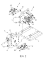
Figure 2 is an exploded perspective view of the preferred embodiment of a wire drawing apparatus according to the present invention; -
Figure 3 is a cross sectional view of the preferred embodiment; and -
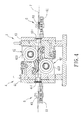
Figure 4 is a cross sectional view illustrating the wire drawing apparatus of the preferred embodiment performing wire drawing on a metal wire. - Referring to
Figures 2 and3 , the preferred embodiment of a wire drawing apparatus of the present invention includes a base 3, two wirepressing devices 4 disposed on the base 3, two lubricating units 5 respectively disposed on the wirepressing devices 4, and twoguide units 6 respectively disposed on the wirepressing devices 4. - Each
pressing device 4 includes amain body 41 assembled with the base 3 and threeroller units 42 assembled on themain body 41. Themain body 41 has ahole 411 through which a metal wire 7 is extended, and theroller units 42 are assembled relative to thehole 411 in an equiangularly displaced manner for surrounding and applying compression forces on the metal wire 7. Eachroller unit 42 includes aneccentric shaft 421 installed on themain body 41, abearing 422 sleeved on theeccentric shaft 421, aroller body 423 installed on thebearing 422 for contacting the metal wire 7, and a plurality of leak-proofing members 424 sleeved on theeccentric shaft 421 and positioned in between theeccentric shaft 421 and theroller body 423. - Each lubricating unit 5 includes a
lubricant inlet 51 provided on themain body 41, alubricant outlet 53 provided on themain body 41, and threepassages 52 formed respectively in theroller units 42. The threepassages 52 are in fluid communication with thelubricant inlet 51 and the lubricant outlet 53 (since allpassages 52 have the same configuration, only onepassage 52 is shown inFigure 3 ). Eachpassage 52 includes aninlet section 521 in fluid communication with thelubricant inlet 51 and disposed in theeccentric shaft 421, anoutlet section 523 in fluid communication with thelubricant outlet 53 and disposed in theeccentric shaft 421, and alubricating section 522 that is in fluid communication with theinlet section 521 and theoutlet section 523 and that is formed through thebearing 422. Eachguide unit 6 includes abase part 61 assembled to themain body 41 of the correspondingwire pressing device 4 and threeguide wheels 62 that are disposed rotatably on thebase part 61 and that provide a winding path for the metal wire 7. Theguide unit 6 and theroller units 42 are disposed on opposite sides of themain body 41 of the correspondingwire pressing device 4, and the winding path provided by theguide wheels 62 is aligned with thehole 411 in themain body 41 of the correspondingwire pressing device 4. - Referring to
Figure 4 , a driver unit (not shown in the Figure), by pulling the metal wire 7, enables the metal wire 7 to first go around and through the threeguide wheels 62 of one of theguide units 6, and then passes through thehole 411 of themain body 41 of one of the wirepressing devices 4. The metal wire 7 is then surrounded and pressed by theroller bodies 423 of theroller units 42 of one of the wirepressing devices 4, causing the diameter of the metal wire 7 to be reduced. The metal wire 7 is then pressed again by theroller bodies 423 of the other one of the wirepressing devices 4, and exits through thehole 411 of themain body 41 of the other one of the wirepressing devices 4. Finally, the metal wire 7 that goes around and passes through the threeguide wheels 62 of the other one of theguide units 6 is reduced to a smaller diameter. - Preferably, the metal wire 7 in this preferred embodiment is made of low carbon steel, and the diameter of which is reduced from 5.5mm to 1.0mm through the wire drawing process. However, the material and diameter of the metal wire 7 are not limited to such.
- Referring to
Figure 3 , at the same time the metal wire 7 is being pulled, a pump (not shown in the Figure) injects a lubricant into thelubricant inlet 51 of each lubricating unit 5 (seeFigure 2 ), causing the lubricant to enter, in the direction as indicated by the arrow A inFigure 3 , theeccentric shaft 421 through theinlet section 521 of thecorresponding passage 52. The lubricant then passes through thelubricating section 522 to cool theeccentric shaft 421 and thebearing 422 of thecorresponding roller units 42. Finally, the lubricant exits theeccentric shaft 421 through theoutlet section 523 of thecorresponding passage 52 in the direction as indicated by the arrow B inFigure 3 and exits the wirepressing devices 4 through thelubricant outlets 53 of the lubricating units 5. The leak-proofing members 424 prevent lubricant from leaking through theeccentric shaft 421 and theroller body 423. - Referring to
Figures 3 and4 , in the pulling process of the metal wire 7, theguide wheels 62 of theguide units 6 enable the metal wire 7 to stably enter and exit theholes 411 of the wirepressing devices 4 and to be stably press rolled by theroller units 42. Since theroller units 42 of the wirepressing devices 4 press roll the metal wire 7 to reduce diameter of the same, the friction produced is minimal and the application of lubricating powder onto the metal wire 7 is therefore not required. Also, since the roller press method covers a large surface area of the metal wire 7, the number of times of wire drawing required for achieving a desired diameter is reduced and therefore the speed of manufacturing is increased. - Furthermore, when the lubricant passes through the
passages 52 of the lubricating units 5, it lubricates and extends the life span of thebearings 422. The lubricant also provides a cooling effect by drawing heat away from theroller units 42 when they are rolling, reducing the likelihood of deterioration of the material of theroller units 42. - The design of the wire drawing apparatus as described hereinabove possesses the following advantages:
- 1. High production speed and requires no lubricating powder on the metal wire:
- Since the
roller bodies 423 of theroller units 42 utilize a press rolling process to reduce the diameter of the metal wire 7, the friction produced is small, and therefore lubricating powder that harms human respiratory system and manufacturing equipments is not used. Since the press rolling process can achieve a greater rate of change of the cross section on the metal wire 7, the required number of times of wire drawing on the metal wire 7 is reduced. In this embodiment, the press rolling process can achieve an output of 1000-1200 meters of the metal wire per minute. Furthermore, since the friction is significantly reduced, the power required by a motor (not shown inFigure 4 ) to draw the metal wire 7 can also be reduced significantly.
- Since the
- 2. Longer life span:
- The lubricant that circulates in the lubricating unit 5 enables the
eccentric shaft 421, thebearing 422 and theroller body 423 of eachroller unit 42 to be lubricated when press rolling. Furthermore, the heat produced in theroller units 42 can be cooled by the lubricant, and the deformation and the deterioration in the material of theroller units 42 due to high temperature can be prevented, thus prolonging the life span of theroller units 42. In the prior art, for every 10 tons of the metal wire 7 drawn, the die 12 (inFigure 1 ) has to be replaced with a new one. On the other hand, the wire drawing apparatus of the present invention only requires a replacement of theroller units 42 for every 2000-5000 tons of the metal wire 7 drawn, thereby reducing the frequency of replacement significantly.
- The lubricant that circulates in the lubricating unit 5 enables the
Claims (5)
- A wire drawing apparatus characterized by:a wire pressing device (4) including a main body (41) and a plurality of roller units (42) assembled on the main body (41), the main body (41) having a hole (411) through which a metal wire (7) is extended, the roller units (42) being assembled relative to the hole (411) for surrounding and applying compression forces on the metal wire (7); anda lubricating unit (5) disposed on the wire pressing device (4) and including a lubricant inlet (51) provided on the main body (41), a lubricant outlet (53) provided on the main body (41), and a plurality of passages (52) formed respectively in the roller units (42), each of the passages (52) being in fluid communication with the lubricant inlet (51) and the lubricant outlet (53).
- The wire drawing apparatus as claimed in Claim 1, characterized in that each of the roller units (42) includes an eccentric shaft (421) installed on the main body (41), a bearing (422) sleeved on the eccentric shaft (421), and a roller body (423) installed on the bearing (422) for contacting the metal wire (7), and each of the passages (52) of the lubricating unit (5) includes an inlet section (521) in fluid communication with the lubricant inlet (51) and disposed in the eccentric shaft (421), an outlet section (523) in fluid communication with the lubricant outlet (53) and disposed in the eccentric shaft (421), and a lubricating section (522) in fluid communication with the inlet section (521) and the outlet section (523) and formed through the bearing (422).
- The wire drawing apparatus as claimed in Claim 2, characterized in that the wire pressing device (4) further includes a plurality of leak-proofing members (424) sleeved on the eccentric shaft (421) and positioned in between the eccentric shaft (421) and the roller body (423).
- The wire drawing apparatus as claimed in any one of Claims 1 to 3, further characterized by a guide unit (6) including a base part (61) assembled to the main body (41) of the wire pressing device (4) and a plurality of guide wheels (62) disposed rotatably on the base part (61) and providing a winding path for the metal wire (7).
- The wire drawing apparatus as claimed in Claim 4, characterized in that the guide unit (6) and the roller units (42) are disposed on opposite sides of the main body (41) of the wire pressing device (4).
Applications Claiming Priority (1)
| Application Number | Priority Date | Filing Date | Title |
|---|---|---|---|
| TW100223494U TWM427214U (en) | 2011-12-13 | 2011-12-13 | Sealed oil path type roller apparatus |
Publications (2)
| Publication Number | Publication Date |
|---|---|
| EP2604353A1 true EP2604353A1 (en) | 2013-06-19 |
| EP2604353B1 EP2604353B1 (en) | 2015-07-22 |
Family
ID=46464321
Family Applications (1)
| Application Number | Title | Priority Date | Filing Date |
|---|---|---|---|
| EP12196664.2A Active EP2604353B1 (en) | 2011-12-13 | 2012-12-12 | Wire drawing apparatus with roller units |
Country Status (2)
| Country | Link |
|---|---|
| EP (1) | EP2604353B1 (en) |
| TW (1) | TWM427214U (en) |
Cited By (1)
| Publication number | Priority date | Publication date | Assignee | Title |
|---|---|---|---|---|
| CN110216161A (en) * | 2019-07-17 | 2019-09-10 | 高特(江苏)新材料有限公司 | A kind of diamond wire bus wire-drawing die |
Families Citing this family (1)
| Publication number | Priority date | Publication date | Assignee | Title |
|---|---|---|---|---|
| CN103390851B (en) * | 2013-04-22 | 2016-02-10 | 华瑞电器股份有限公司 | Copper bar finish draw equipment |
Citations (3)
| Publication number | Priority date | Publication date | Assignee | Title |
|---|---|---|---|---|
| US2101959A (en) * | 1933-08-16 | 1937-12-14 | Julius Kahn | Metal drawing apparatus |
| GB949177A (en) * | 1959-04-17 | 1964-02-12 | Fischer & Co | Deformation of bars and other material |
| TW380174B (en) | 1995-02-10 | 2000-01-21 | Barmag Barmer Maschf | Method and apparatus for producing a multifilament yarn |
-
2011
- 2011-12-13 TW TW100223494U patent/TWM427214U/en not_active IP Right Cessation
-
2012
- 2012-12-12 EP EP12196664.2A patent/EP2604353B1/en active Active
Patent Citations (3)
| Publication number | Priority date | Publication date | Assignee | Title |
|---|---|---|---|---|
| US2101959A (en) * | 1933-08-16 | 1937-12-14 | Julius Kahn | Metal drawing apparatus |
| GB949177A (en) * | 1959-04-17 | 1964-02-12 | Fischer & Co | Deformation of bars and other material |
| TW380174B (en) | 1995-02-10 | 2000-01-21 | Barmag Barmer Maschf | Method and apparatus for producing a multifilament yarn |
Cited By (2)
| Publication number | Priority date | Publication date | Assignee | Title |
|---|---|---|---|---|
| CN110216161A (en) * | 2019-07-17 | 2019-09-10 | 高特(江苏)新材料有限公司 | A kind of diamond wire bus wire-drawing die |
| CN110216161B (en) * | 2019-07-17 | 2023-12-08 | 高特(江苏)新材料有限公司 | A kind of diamond wire busbar drawing die |
Also Published As
| Publication number | Publication date |
|---|---|
| TWM427214U (en) | 2012-04-21 |
| EP2604353B1 (en) | 2015-07-22 |
Similar Documents
| Publication | Publication Date | Title |
|---|---|---|
| EP2604353B1 (en) | Wire drawing apparatus with roller units | |
| CN106607472B (en) | A kind of copper pipe internal thread forming device | |
| CN215928134U (en) | Split air foil thrust bearing | |
| CN102009065B (en) | Method and device for rolling metal section with asymmetric cross section | |
| CN114671297B (en) | Steel wire rope coiling machine | |
| CN113042555A (en) | Water tank wire drawing machine for drawing soft solder alloy by using roller die | |
| CN205680505U (en) | Concha Arcae interlocking armoring machine roller shaping guide mechanism | |
| CN222790193U (en) | A copper rod coiling feeding pipe structure | |
| EP3195423B1 (en) | Rotary electrical conductor. | |
| CN101786111A (en) | Device and method thereof for controlling width tolerance of molybdenum strip | |
| CN211803136U (en) | Wire drawing roller mold | |
| CN211594059U (en) | Turntable heavy-load roller way | |
| JP3486372B2 (en) | Wire drawing method and device | |
| CN202290813U (en) | Roller die | |
| CN118989010A (en) | Cold drawing wire drawing machine for tubular pile production and use method thereof | |
| CN110899353A (en) | Wire drawing roller mold | |
| CN105290433B (en) | A kind of device for thinning of turning iron filings | |
| CN201659210U (en) | The roller of the rolling die of the steel cylinder drawing machine | |
| CN223789351U (en) | Stamping die for ventilation holes of generator rotor copper busbar | |
| CN216788991U (en) | Needle bearing with abrasionproof decreases function | |
| CN223405672U (en) | A fully automatic drawing device for galvanized flat wire | |
| CN119951890A (en) | Metal cold working wire drawing device | |
| CN216463483U (en) | Machining device with spiral guide wheel | |
| CN214639240U (en) | Self-lubricating idler gear structure of stamping sheet coil straightening machine | |
| CN105913976B (en) | Corrugation interlocks armoring machine roller shaping guide mechanism |
Legal Events
| Date | Code | Title | Description |
|---|---|---|---|
| PUAI | Public reference made under article 153(3) epc to a published international application that has entered the european phase |
Free format text: ORIGINAL CODE: 0009012 |
|
| AK | Designated contracting states |
Kind code of ref document: A1 Designated state(s): AL AT BE BG CH CY CZ DE DK EE ES FI FR GB GR HR HU IE IS IT LI LT LU LV MC MK MT NL NO PL PT RO RS SE SI SK SM TR |
|
| AX | Request for extension of the european patent |
Extension state: BA ME |
|
| 17P | Request for examination filed |
Effective date: 20130826 |
|
| RBV | Designated contracting states (corrected) |
Designated state(s): AL AT BE BG CH CY CZ DE DK EE ES FI FR GB GR HR HU IE IS IT LI LT LU LV MC MK MT NL NO PL PT RO RS SE SI SK SM TR |
|
| GRAP | Despatch of communication of intention to grant a patent |
Free format text: ORIGINAL CODE: EPIDOSNIGR1 |
|
| INTG | Intention to grant announced |
Effective date: 20150311 |
|
| GRAS | Grant fee paid |
Free format text: ORIGINAL CODE: EPIDOSNIGR3 |
|
| GRAA | (expected) grant |
Free format text: ORIGINAL CODE: 0009210 |
|
| AK | Designated contracting states |
Kind code of ref document: B1 Designated state(s): AL AT BE BG CH CY CZ DE DK EE ES FI FR GB GR HR HU IE IS IT LI LT LU LV MC MK MT NL NO PL PT RO RS SE SI SK SM TR |
|
| REG | Reference to a national code |
Ref country code: GB Ref legal event code: FG4D |
|
| REG | Reference to a national code |
Ref country code: CH Ref legal event code: EP |
|
| REG | Reference to a national code |
Ref country code: IE Ref legal event code: FG4D |
|
| REG | Reference to a national code |
Ref country code: AT Ref legal event code: REF Ref document number: 737591 Country of ref document: AT Kind code of ref document: T Effective date: 20150815 |
|
| REG | Reference to a national code |
Ref country code: DE Ref legal event code: R096 Ref document number: 602012008914 Country of ref document: DE |
|
| REG | Reference to a national code |
Ref country code: AT Ref legal event code: MK05 Ref document number: 737591 Country of ref document: AT Kind code of ref document: T Effective date: 20150722 |
|
| REG | Reference to a national code |
Ref country code: LT Ref legal event code: MG4D |
|
| REG | Reference to a national code |
Ref country code: NL Ref legal event code: MP Effective date: 20150722 |
|
| PG25 | Lapsed in a contracting state [announced via postgrant information from national office to epo] |
Ref country code: NO Free format text: LAPSE BECAUSE OF FAILURE TO SUBMIT A TRANSLATION OF THE DESCRIPTION OR TO PAY THE FEE WITHIN THE PRESCRIBED TIME-LIMIT Effective date: 20151022 Ref country code: GR Free format text: LAPSE BECAUSE OF FAILURE TO SUBMIT A TRANSLATION OF THE DESCRIPTION OR TO PAY THE FEE WITHIN THE PRESCRIBED TIME-LIMIT Effective date: 20151023 Ref country code: LT Free format text: LAPSE BECAUSE OF FAILURE TO SUBMIT A TRANSLATION OF THE DESCRIPTION OR TO PAY THE FEE WITHIN THE PRESCRIBED TIME-LIMIT Effective date: 20150722 Ref country code: FI Free format text: LAPSE BECAUSE OF FAILURE TO SUBMIT A TRANSLATION OF THE DESCRIPTION OR TO PAY THE FEE WITHIN THE PRESCRIBED TIME-LIMIT Effective date: 20150722 Ref country code: LV Free format text: LAPSE BECAUSE OF FAILURE TO SUBMIT A TRANSLATION OF THE DESCRIPTION OR TO PAY THE FEE WITHIN THE PRESCRIBED TIME-LIMIT Effective date: 20150722 |
|
| PG25 | Lapsed in a contracting state [announced via postgrant information from national office to epo] |
Ref country code: RS Free format text: LAPSE BECAUSE OF FAILURE TO SUBMIT A TRANSLATION OF THE DESCRIPTION OR TO PAY THE FEE WITHIN THE PRESCRIBED TIME-LIMIT Effective date: 20150722 Ref country code: IS Free format text: LAPSE BECAUSE OF FAILURE TO SUBMIT A TRANSLATION OF THE DESCRIPTION OR TO PAY THE FEE WITHIN THE PRESCRIBED TIME-LIMIT Effective date: 20151122 Ref country code: PL Free format text: LAPSE BECAUSE OF FAILURE TO SUBMIT A TRANSLATION OF THE DESCRIPTION OR TO PAY THE FEE WITHIN THE PRESCRIBED TIME-LIMIT Effective date: 20150722 Ref country code: HR Free format text: LAPSE BECAUSE OF FAILURE TO SUBMIT A TRANSLATION OF THE DESCRIPTION OR TO PAY THE FEE WITHIN THE PRESCRIBED TIME-LIMIT Effective date: 20150722 Ref country code: AT Free format text: LAPSE BECAUSE OF FAILURE TO SUBMIT A TRANSLATION OF THE DESCRIPTION OR TO PAY THE FEE WITHIN THE PRESCRIBED TIME-LIMIT Effective date: 20150722 Ref country code: PT Free format text: LAPSE BECAUSE OF FAILURE TO SUBMIT A TRANSLATION OF THE DESCRIPTION OR TO PAY THE FEE WITHIN THE PRESCRIBED TIME-LIMIT Effective date: 20151123 Ref country code: SE Free format text: LAPSE BECAUSE OF FAILURE TO SUBMIT A TRANSLATION OF THE DESCRIPTION OR TO PAY THE FEE WITHIN THE PRESCRIBED TIME-LIMIT Effective date: 20150722 Ref country code: ES Free format text: LAPSE BECAUSE OF FAILURE TO SUBMIT A TRANSLATION OF THE DESCRIPTION OR TO PAY THE FEE WITHIN THE PRESCRIBED TIME-LIMIT Effective date: 20150722 |
|
| REG | Reference to a national code |
Ref country code: DE Ref legal event code: R097 Ref document number: 602012008914 Country of ref document: DE |
|
| PG25 | Lapsed in a contracting state [announced via postgrant information from national office to epo] |
Ref country code: EE Free format text: LAPSE BECAUSE OF FAILURE TO SUBMIT A TRANSLATION OF THE DESCRIPTION OR TO PAY THE FEE WITHIN THE PRESCRIBED TIME-LIMIT Effective date: 20150722 Ref country code: SK Free format text: LAPSE BECAUSE OF FAILURE TO SUBMIT A TRANSLATION OF THE DESCRIPTION OR TO PAY THE FEE WITHIN THE PRESCRIBED TIME-LIMIT Effective date: 20150722 Ref country code: DK Free format text: LAPSE BECAUSE OF FAILURE TO SUBMIT A TRANSLATION OF THE DESCRIPTION OR TO PAY THE FEE WITHIN THE PRESCRIBED TIME-LIMIT Effective date: 20150722 Ref country code: CZ Free format text: LAPSE BECAUSE OF FAILURE TO SUBMIT A TRANSLATION OF THE DESCRIPTION OR TO PAY THE FEE WITHIN THE PRESCRIBED TIME-LIMIT Effective date: 20150722 |
|
| PLBE | No opposition filed within time limit |
Free format text: ORIGINAL CODE: 0009261 |
|
| STAA | Information on the status of an ep patent application or granted ep patent |
Free format text: STATUS: NO OPPOSITION FILED WITHIN TIME LIMIT |
|
| PG25 | Lapsed in a contracting state [announced via postgrant information from national office to epo] |
Ref country code: RO Free format text: LAPSE BECAUSE OF FAILURE TO SUBMIT A TRANSLATION OF THE DESCRIPTION OR TO PAY THE FEE WITHIN THE PRESCRIBED TIME-LIMIT Effective date: 20150722 Ref country code: BE Free format text: LAPSE BECAUSE OF NON-PAYMENT OF DUE FEES Effective date: 20151231 |
|
| 26N | No opposition filed |
Effective date: 20160425 |
|
| PG25 | Lapsed in a contracting state [announced via postgrant information from national office to epo] |
Ref country code: LU Free format text: LAPSE BECAUSE OF FAILURE TO SUBMIT A TRANSLATION OF THE DESCRIPTION OR TO PAY THE FEE WITHIN THE PRESCRIBED TIME-LIMIT Effective date: 20151212 Ref country code: MC Free format text: LAPSE BECAUSE OF FAILURE TO SUBMIT A TRANSLATION OF THE DESCRIPTION OR TO PAY THE FEE WITHIN THE PRESCRIBED TIME-LIMIT Effective date: 20150722 |
|
| REG | Reference to a national code |
Ref country code: CH Ref legal event code: PL |
|
| PG25 | Lapsed in a contracting state [announced via postgrant information from national office to epo] |
Ref country code: SI Free format text: LAPSE BECAUSE OF FAILURE TO SUBMIT A TRANSLATION OF THE DESCRIPTION OR TO PAY THE FEE WITHIN THE PRESCRIBED TIME-LIMIT Effective date: 20150722 |
|
| REG | Reference to a national code |
Ref country code: IE Ref legal event code: MM4A |
|
| REG | Reference to a national code |
Ref country code: FR Ref legal event code: ST Effective date: 20160831 |
|
| PG25 | Lapsed in a contracting state [announced via postgrant information from national office to epo] |
Ref country code: CH Free format text: LAPSE BECAUSE OF NON-PAYMENT OF DUE FEES Effective date: 20151231 Ref country code: IE Free format text: LAPSE BECAUSE OF NON-PAYMENT OF DUE FEES Effective date: 20151212 Ref country code: LI Free format text: LAPSE BECAUSE OF NON-PAYMENT OF DUE FEES Effective date: 20151231 |
|
| PG25 | Lapsed in a contracting state [announced via postgrant information from national office to epo] |
Ref country code: FR Free format text: LAPSE BECAUSE OF NON-PAYMENT OF DUE FEES Effective date: 20151231 |
|
| PG25 | Lapsed in a contracting state [announced via postgrant information from national office to epo] |
Ref country code: BE Free format text: LAPSE BECAUSE OF FAILURE TO SUBMIT A TRANSLATION OF THE DESCRIPTION OR TO PAY THE FEE WITHIN THE PRESCRIBED TIME-LIMIT Effective date: 20150722 |
|
| PG25 | Lapsed in a contracting state [announced via postgrant information from national office to epo] |
Ref country code: BG Free format text: LAPSE BECAUSE OF FAILURE TO SUBMIT A TRANSLATION OF THE DESCRIPTION OR TO PAY THE FEE WITHIN THE PRESCRIBED TIME-LIMIT Effective date: 20150722 Ref country code: SM Free format text: LAPSE BECAUSE OF FAILURE TO SUBMIT A TRANSLATION OF THE DESCRIPTION OR TO PAY THE FEE WITHIN THE PRESCRIBED TIME-LIMIT Effective date: 20150722 Ref country code: HU Free format text: LAPSE BECAUSE OF FAILURE TO SUBMIT A TRANSLATION OF THE DESCRIPTION OR TO PAY THE FEE WITHIN THE PRESCRIBED TIME-LIMIT; INVALID AB INITIO Effective date: 20121212 |
|
| PG25 | Lapsed in a contracting state [announced via postgrant information from national office to epo] |
Ref country code: CY Free format text: LAPSE BECAUSE OF FAILURE TO SUBMIT A TRANSLATION OF THE DESCRIPTION OR TO PAY THE FEE WITHIN THE PRESCRIBED TIME-LIMIT Effective date: 20150722 Ref country code: NL Free format text: LAPSE BECAUSE OF FAILURE TO SUBMIT A TRANSLATION OF THE DESCRIPTION OR TO PAY THE FEE WITHIN THE PRESCRIBED TIME-LIMIT Effective date: 20150722 |
|
| GBPC | Gb: european patent ceased through non-payment of renewal fee |
Effective date: 20161212 |
|
| PG25 | Lapsed in a contracting state [announced via postgrant information from national office to epo] |
Ref country code: MT Free format text: LAPSE BECAUSE OF FAILURE TO SUBMIT A TRANSLATION OF THE DESCRIPTION OR TO PAY THE FEE WITHIN THE PRESCRIBED TIME-LIMIT Effective date: 20150722 |
|
| PG25 | Lapsed in a contracting state [announced via postgrant information from national office to epo] |
Ref country code: GB Free format text: LAPSE BECAUSE OF NON-PAYMENT OF DUE FEES Effective date: 20161212 |
|
| PG25 | Lapsed in a contracting state [announced via postgrant information from national office to epo] |
Ref country code: MK Free format text: LAPSE BECAUSE OF FAILURE TO SUBMIT A TRANSLATION OF THE DESCRIPTION OR TO PAY THE FEE WITHIN THE PRESCRIBED TIME-LIMIT Effective date: 20150722 |
|
| PG25 | Lapsed in a contracting state [announced via postgrant information from national office to epo] |
Ref country code: AL Free format text: LAPSE BECAUSE OF FAILURE TO SUBMIT A TRANSLATION OF THE DESCRIPTION OR TO PAY THE FEE WITHIN THE PRESCRIBED TIME-LIMIT Effective date: 20150722 |
|
| P01 | Opt-out of the competence of the unified patent court (upc) registered |
Effective date: 20230529 |
|
| PGFP | Annual fee paid to national office [announced via postgrant information from national office to epo] |
Ref country code: DE Payment date: 20250619 Year of fee payment: 14 |
|
| PGFP | Annual fee paid to national office [announced via postgrant information from national office to epo] |
Ref country code: IT Payment date: 20251218 Year of fee payment: 14 |
|
| PGFP | Annual fee paid to national office [announced via postgrant information from national office to epo] |
Ref country code: TR Payment date: 20251121 Year of fee payment: 14 |