EP2604166A1 - Laundry machine with support system for a heating element - Google Patents
Laundry machine with support system for a heating element Download PDFInfo
- Publication number
- EP2604166A1 EP2604166A1 EP11193414.7A EP11193414A EP2604166A1 EP 2604166 A1 EP2604166 A1 EP 2604166A1 EP 11193414 A EP11193414 A EP 11193414A EP 2604166 A1 EP2604166 A1 EP 2604166A1
- Authority
- EP
- European Patent Office
- Prior art keywords
- support element
- sump
- laundry machine
- machine according
- lateral
- Prior art date
- Legal status (The legal status is an assumption and is not a legal conclusion. Google has not performed a legal analysis and makes no representation as to the accuracy of the status listed.)
- Granted
Links
- 238000010438 heat treatment Methods 0.000 title claims abstract description 48
- 238000005406 washing Methods 0.000 claims abstract description 47
- 239000007788 liquid Substances 0.000 claims abstract description 17
- 238000001035 drying Methods 0.000 claims abstract description 6
- 238000000034 method Methods 0.000 claims description 7
- 238000005452 bending Methods 0.000 claims description 3
- 239000003599 detergent Substances 0.000 description 7
- 239000012530 fluid Substances 0.000 description 5
- 238000009825 accumulation Methods 0.000 description 4
- 239000013505 freshwater Substances 0.000 description 4
- 239000004753 textile Substances 0.000 description 4
- XLYOFNOQVPJJNP-UHFFFAOYSA-N water Substances O XLYOFNOQVPJJNP-UHFFFAOYSA-N 0.000 description 4
- 230000002441 reversible effect Effects 0.000 description 2
- 241000894006 Bacteria Species 0.000 description 1
- 238000010276 construction Methods 0.000 description 1
- 230000004907 flux Effects 0.000 description 1
- 238000004519 manufacturing process Methods 0.000 description 1
- 239000002184 metal Substances 0.000 description 1
- 230000035943 smell Effects 0.000 description 1
- 230000035882 stress Effects 0.000 description 1
- 230000008646 thermal stress Effects 0.000 description 1
Images


Classifications
-
- D—TEXTILES; PAPER
- D06—TREATMENT OF TEXTILES OR THE LIKE; LAUNDERING; FLEXIBLE MATERIALS NOT OTHERWISE PROVIDED FOR
- D06F—LAUNDERING, DRYING, IRONING, PRESSING OR FOLDING TEXTILE ARTICLES
- D06F39/00—Details of washing machines not specific to a single type of machines covered by groups D06F9/00 - D06F27/00
- D06F39/04—Heating arrangements
Definitions
- the present invention relates to a laundry machine, such as a washing machine or a washing machine with drying function.
- Known laundry machine as washing machines or washer-driers usually comprise a washing tub (or simply tub) arranged within a housing or casing. Inside the washing tub a drum, wherein laundry to be cleaned can be loaded-unloaded, is rotatably supported.
- the tub has a bottom section which forms a sump (or draining region), fluidly connected to a drain pump and thereby in fluid connection to a drainage duct.
- the sump is a sort of bulge or "basing-shaped" region provided in the bottom of the tub, which protrudes externally from the substantially cylindrical lateral surface of the tub, and which is typically made in a single-piece construction (i.e.
- washing liquid collects.
- Fresh water is typically supplied to the laundry machine via a water supply conduit and is preferably guided through a detergent feeding drawer wherein detergent or other washing/rinsing products (e.g. softener) is provided.
- detergent or other washing/rinsing products e.g. softener
- washing liquid e.g. water alone or water mixed with detergent/softener
- a heating element is arranged for heating up the washing liquid to a desired temperature.
- the heating element is typically supported by one or more supporting elements fixed to the bottom of the sump in such a way to keep the heating element spaced from the latter (i.e. the bottom).
- Document EP 2 122 038 B1 describes an example of a securing element (e.g. a supporting element) for a tubular heater (i.e. a heating element) of a washing machine, wherein the securing element has a first mounting portion for connecting the securing element to a mounting base of the washing machine and a clip portion extending upwards from the mounting base.
- a securing element e.g. a supporting element
- a tubular heater i.e. a heating element
- a laundry machine such as a washing machine or a washing machine with drying function, comprises:
- An arrangement according to the invention results in that fluff or lint which sinks to the ground of the sump cannot be deposited at or on a component which is fastened on the ground any more.
- the support element is attached at least to the first lateral wall of the sump.
- the attachment of the support element to a lateral wall allows a stable and easy fixation of the support element wherein it is avoided that the support element is fixed to the bottom of the sump.
- the sump comprises at least one second lateral wall, arranged opposite to the first lateral wall, wherein at least one of the lateral walls is provided with a slot or groove, in which the support element (18) is at least partially supported.
- the support element can engage or be guided in the slot.
- an advantageous support for the heating element is created.
- the support element comprises at least one lateral arm and at least one first portion, each first portion arranged adjacent to a respective lateral arm.
- Such a configuration allows an arrangement of the support element upon lateral elements.
- At least one 90° angle is formed between a lateral arm and the adjacent first portion.
- the lateral arm can serve as a bearing or supporting section of the support element, wherein the first portion can connect the lateral arm to the remaining parts of the support element.
- the support element comprises two lateral arms and two adjacent first portions, wherein both said first lateral wall and said second lateral wall are provided with a slot or groove, in which the support element is at least partially supported, and wherein said support element is determined in its position relative to the sump by its two lateral arms which are arranged respectively inside the slots of said first and second lateral walls and by two first portions which abut to respective endings of said slots.
- the lateral arms of the support element can be inserted or guided within the elongated slots and the support element can extend perpendicular to the lateral walls.
- an advantageous support for the heating element is created.
- the support element can be attached in an end or final position without the need of adjusting means. After attaching the support element in its final position, the heating element can be mounted to the machine.
- the support element has at least one curved portion providing resilience for the support element.
- Resilient properties of the support element are advantageous to the compensation of tolerances of manufacturing of the sump or the heating element. It is also possible to compensate thermal stress from the heating element during operation of the appliance by means of such a curved portion.
- the support element has two curved portions which are connected by a connection portion that forms a middle part of the support element.
- the provision of two curved portions allows supporting a heating element with at least two tubes which are arranged to fit within the curved portions. Resilience and a fit or seat for a heating element having at least two tubes is provided by the same means.
- the support element is formed in such way that it can be mounted in a first position and in a second position relative to the sump, wherein the first position is rotated through 180° relative to the second position and wherein the support element mounted in the first position supports the heating element in the same position relative to the sump as the support element mounted in the second position.
- the at least one support element is formed from a wire, in particular formed by one or more bending processes.
- the support element can be manufactured in an easy way in a large number of pieces providing good quality at the same time.
- the support element is dimensioned such that it is slightly deformed (preferably elastically) in a mounted state, wherein the deformation causes a clamping force which secures the support element in its position relative to the sump.
- the support element receives a sufficient force to fix it in its final position and secures it in the mounting process or during regular operation of the laundry machine.
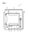
- FIG 1 illustrates a laundry machine 1 which can be a washing machine, a washing machine with drying function (so called washer/dryer).
- the laundry machine 1 comprises a washing tub 2 arranged within a housing or casing of the laundry machine 1. Inside the washing tub 2 a drum 3, wherein laundry to be cleaned can be loaded/unloaded, is rotatably supported; the drum 3 can be driven in a rotation movement by a drive assembly 4 which comprises a motor.
- the washing tub 2 has a bottom section 5 which forms a sump 6.
- the sump 6 is a sort of bulge or "basing-shaped" region provided in the bottom section of the tub 2, which preferably protrudes externally from the substantially cylindrical lateral surface of the tub 5.
- the sump 6 is in fluid connection via a second connection conduit 12 to a drain pump 7 and thereby in fluid connection to a drainage 8.
- Fresh water is supplied to the laundry machine 1 via a water supply conduit 9 and is preferably guided through a detergent feeding drawer 10 wherein detergent is provided.
- detergent is provided.
- fresh water and detergent are mixed up, being now a washing liquid, and guided through a first connection conduit 11 into the interior of the washing tub 2.
- the washing liquid is collected at least partially in the sump 6 wherein a heating element 13 is arranged.
- the heating element 13 can heat up the washing liquid to a desired temperature. Because of a plurality of holes in the shell of the drum 3, the interior of the drum 3 is in fluid connection with the interior of the washing tub 2.
- FIG 2 and FIG 3 show more detailed views of the sump 6 of washing machine 1.
- the sump 6 is defined by a bottom wall 14, a first lateral wall 15 and a second lateral wall 16.
- the heating element 13 is arranged within the sump 6 in a configuration that the heating element 13 is not in direct contact with the bottom wall or the lateral walls 14, 15, 16 but in a connection that it is allowed to heat the washing liquid inside the sump 6.
- Slots 17 or grooves are arranged on an interior side of the first lateral wall 15 and also on an interior side of the second lateral wall 16.
- the slots 17 are provided until a certain position in the lateral walls 15, 16.
- a support element 18 is supported in the slots 17.
- the heating element 13 is supported by the support element 18.
- An end section of the heating element 13 is fixedly fastened to a rear wall of the sump 6 in a fluid tight manner (not shown), such that the electric connectors of the heating element are arranged on the exterior of the tub 5.
- the support element 18 in FIG 2 can be arranged in a reverse manner according to FIG 3 .
- the support element 18 in FIG 3 is arranged upside down with respect to FIG 2 .
- Both figures 2 and 3 show that no supporting element or other constructive component is arranged at or on the bottom wall 14 of the sump 6.
- the reversible design of the support element 18 allows that no particular attention has to be paid to the orientation of the support element 18 in the mounting or assembling process of the laundry machine 1.
- the support element 18 can be arranged in two distinct positions within the sump, one position rotated through 180° relative to the other position. In both different positions of the support element 18, the two curved portions 23 of the support element (which will be better described in the following) are arranged in the same position enabling to retain or hold or support the heating element 13 in its intended position relative to the bottom wall 14 and the lateral walls 15, 16 of the sump 6.
- FIG 4 shows a sectional view of the sump 6. It can be seen that the bottom wall 14 is free from constructive elements.
- the heating element 13 is in a form fit connection with the support element 18 and, thus, supported in a position above the bottom wall 14.
- the slots 17 are provided in the lateral walls 15, 16.
- the support element 18 can also be arranged in a turned around configuration.
- the support element 18 can be formed to support the heating element 13 also with respect to lateral movements. In other words, the support element can fix or retain or clamp the heating element 13 in a lateral direction.
- FIG 5 shows a support element 18 in detail.
- the support element 18 is formed as a metal part, e.g. from a wire, and manufactured by bending processes.
- the support element 18 advantageously comprises lateral arms 19 on each side, being arranged preferably in 90 degrees angular to the other parts of the element.
- the lateral arms 19 are connected to first portions 20, vertical portions 21, second portions 22 and curved portions 23.
- a connection portion 24 forms a middle part of the support element 18.
- the support element 18 is preferably formed substantially symmetrical which allows the mounting of the support element 18 vice versa.
- the curved portions 23 are adapted to the form of the heating element 13 which has a tubular shape. Further the curved portions 23 together with the connection portion 24 provide resilience for the support element 18 allowing compensating tolerances.
- the provision of the support element 18 as a resilient or elastic element allows the compensation of dimensional tolerances with respect to the sump 6 and to the heating element 13.
- optimized positioning or fit of the heating element 13 within the sump 6 is enabled, but also an optimized fit of the heating element 13 in or at the support element 18.
- the curved portions 23 can be formed e.g. in the form of a semi-circle.
- the support element 18 is inserted or drawn or pushed into the slots 17 provided in the lateral walls 15, 16 until the first portions 20 abut to the shoulders or stops formed by the end of the slots 17 in the lateral walls 15, 16.
- the final position of the support element 18 is therefore determined by the position of the endings of the slots 17. Further, the endings of the slots 17 are arranged in a position to place the support element 18 such that the heating element 13 is supported in its front region.
- the support element 18 is fixed into the slots 17 or grooves without screws or other fixing devices.
- the support element 18 can be dimensioned such that, when it is introduced into the slots 17, the support element 18 can be slightly deformed. This causes a stress or tension and the support element 18 tends to restore its not-deformed shape or state. Consequently, e.g. the lateral arms 19 can be pressed against the walls of the slots 17, so as to obtain the fixation.
- the lateral arms 19 and the first portions 20 span or define a plane, wherein the centre points of the curved portions 23 are positioned and wherein also the centre points or centre axes of the tubes of a tubular heating element can be positioned.
- the centre axes of the tubes of the tubular heating element are then arranged substantially parallel to the bottom of the sump 6.
- the present invention allows avoiding the accumulation of lint or fluff in the bottom of the sump (or tub) found in the known laundry machines.
- the arrangement of the support element 18 as shown in FIG 3 might be advantageous, because only the connection portion 24 is positioned between the heating element 13 and the bottom of the sump 6. All other components of the support element 18 are positioned laterally or above relative to the heating element 13. Thus, the free space between the heating element 13 and the bottom of the sump 6 is as large as possible which further reduces the accumulation of lint or fluff.
Landscapes
- Engineering & Computer Science (AREA)
- Textile Engineering (AREA)
- Detail Structures Of Washing Machines And Dryers (AREA)
Abstract
- a treatment container having a bottom section (5), wherein the bottom section (5) comprises or forms a sump (6), wherein the sump (6) has a bottom wall (14) and at least one first lateral wall (15);
- at least one heating element (13) arranged at least partially within the sump (6) for heating up washing liquid being in the sump (6);
- at least one support element (18) arranged at least partially within the sump (6), said support element (18) supports the at least one heating element (13) within the sump (6) and in a distance to the bottom wall (14) of the sump (6),
characterized in that
said support element (18) is spaced from the bottom wall (14) of the sump (6).
Description
- The present invention relates to a laundry machine, such as a washing machine or a washing machine with drying function.
- Known laundry machine as washing machines or washer-driers usually comprise a washing tub (or simply tub) arranged within a housing or casing. Inside the washing tub a drum, wherein laundry to be cleaned can be loaded-unloaded, is rotatably supported. The tub has a bottom section which forms a sump (or draining region), fluidly connected to a drain pump and thereby in fluid connection to a drainage duct. In some known laundry machines the sump is a sort of bulge or "basing-shaped" region provided in the bottom of the tub, which protrudes externally from the substantially cylindrical lateral surface of the tub, and which is typically made in a single-piece construction (i.e. a single body) with the tub: in other known laundry machines the sump substantially coincides with a bottom region of the tub, i.e. it is not a well-defined body, but simply the bottom region of the tub in which washing liquid collects. Fresh water is typically supplied to the laundry machine via a water supply conduit and is preferably guided through a detergent feeding drawer wherein detergent or other washing/rinsing products (e.g. softener) is provided. Thus, fresh water and detergent are mixed up, being now a washing liquid, and guided through a first connection conduit into the interior of the washing tub.
- Inside the tub the washing liquid (e.g. water alone or water mixed with detergent/softener) is collected at least partially in the sump, wherein a heating element is arranged for heating up the washing liquid to a desired temperature. The heating element is typically supported by one or more supporting elements fixed to the bottom of the sump in such a way to keep the heating element spaced from the latter (i.e. the bottom).
-
Document EP 2 122 038 B1 describes an example of a securing element (e.g. a supporting element) for a tubular heater (i.e. a heating element) of a washing machine, wherein the securing element has a first mounting portion for connecting the securing element to a mounting base of the washing machine and a clip portion extending upwards from the mounting base. - In known laundry machines, during a washing cycle, filth and textile fibres separated from the textiles typically form fluff or lint which floats in the washing liquid. This fluff or lint tends to settle in the bottom of the sump, and has to be removed, during the draining phase of the washing cycle, by the flow of washing liquid exiting the tub through the sump due to the suction action of the drain pump.
- These known laundry machines have however the drawback that the supporting element fixed to the bottom of the sump (or of the tub) may catch the fluff or lint settled in the bottom of the sump (or tub), obstructing its draining, with the risk of accumulation of a big amount of fluff or lint in the sump (or bottom of the tub). Lint or fluff accumulation in the sump (or bottom of the tub) may obstruct the draining of the washing liquid, and moreover it may promote the growth of bacteria and the generation of bad smells.
- It is an object of the present invention to provide a laundry machine such as a washing machine or a washing machine with drying function with an advantageous support for the heating element in its sump, which doesn't obstruct the draining of fluff or lint from the bottom of the sump.
- This object of the present invention is achieved by a household appliance according to claim 1.
- According to the present invention a laundry machine such as a washing machine or a washing machine with drying function, comprises:
- a treatment container having a bottom section, wherein the bottom section comprises or forms a sump, wherein the sump has a bottom wall and at least one first lateral wall;
- at least one heating element arranged at least partially within the sump for heating up washing liquid being in the sump;
- at least one support element arranged at least partially within the sump, said support element supports the at least one heating element within the sump and in a distance to the bottom wall of the sump, wherein said support element is spaced from the bottom wall of the sump.
- An arrangement according to the invention results in that fluff or lint which sinks to the ground of the sump cannot be deposited at or on a component which is fastened on the ground any more.
- According to a further embodiment of the invention the support element is attached at least to the first lateral wall of the sump.
- The attachment of the support element to a lateral wall allows a stable and easy fixation of the support element wherein it is avoided that the support element is fixed to the bottom of the sump.
- In a further embodiment of the invention the sump comprises at least one second lateral wall, arranged opposite to the first lateral wall, wherein at least one of the lateral walls is provided with a slot or groove, in which the support element (18) is at least partially supported.
- In such a configuration the support element can engage or be guided in the slot. Thus, an advantageous support for the heating element is created.
- According to a further embodiment of the invention the support element comprises at least one lateral arm and at least one first portion, each first portion arranged adjacent to a respective lateral arm.
- Such a configuration allows an arrangement of the support element upon lateral elements.
- In a further embodiment of the invention at least one 90° angle is formed between a lateral arm and the adjacent first portion.
- Thus, the lateral arm can serve as a bearing or supporting section of the support element, wherein the first portion can connect the lateral arm to the remaining parts of the support element.
- In a further embodiment of the invention the support element comprises two lateral arms and two adjacent first portions, wherein both said first lateral wall and said second lateral wall are provided with a slot or groove, in which the support element is at least partially supported, and wherein said support element is determined in its position relative to the sump by its two lateral arms which are arranged respectively inside the slots of said first and second lateral walls and by two first portions which abut to respective endings of said slots.
- In such a configuration the lateral arms of the support element can be inserted or guided within the elongated slots and the support element can extend perpendicular to the lateral walls. Thus, an advantageous support for the heating element is created. Further the support element can be attached in an end or final position without the need of adjusting means. After attaching the support element in its final position, the heating element can be mounted to the machine.
- According to a further embodiment of the invention the support element has at least one curved portion providing resilience for the support element.
- Resilient properties of the support element are advantageous to the compensation of tolerances of manufacturing of the sump or the heating element. It is also possible to compensate thermal stress from the heating element during operation of the appliance by means of such a curved portion.
- According to a further embodiment of the invention the support element has two curved portions which are connected by a connection portion that forms a middle part of the support element.
- The provision of two curved portions allows supporting a heating element with at least two tubes which are arranged to fit within the curved portions. Resilience and a fit or seat for a heating element having at least two tubes is provided by the same means.
- In a further embodiment of the invention the support element is formed in such way that it can be mounted in a first position and in a second position relative to the sump, wherein the first position is rotated through 180° relative to the second position and wherein the support element mounted in the first position supports the heating element in the same position relative to the sump as the support element mounted in the second position.
- Thus, the worker or assembler needs not to pay particular attention on the orientation of the support element in the mounting process. A possible source of error in the mounting process is excluded.
- According to a further embodiment of the invention the at least one support element is formed from a wire, in particular formed by one or more bending processes.
- Thus, the support element can be manufactured in an easy way in a large number of pieces providing good quality at the same time.
- According to a further embodiment of the invention the support element is dimensioned such that it is slightly deformed (preferably elastically) in a mounted state, wherein the deformation causes a clamping force which secures the support element in its position relative to the sump.
- In this way, the support element receives a sufficient force to fix it in its final position and secures it in the mounting process or during regular operation of the laundry machine.
- The invention will be described in further detail with reference to the drawings, in which
- FIG 1
- illustrates a sectional view of a laundry machine for which a supporting system according to the invention is applicable;
- FIG 2
- illustrates a perspective detailed view of a sump of a laundry machine according to
FIG 1 showing a support system; - FIG 3
- illustrates a perspective detailed view of an alternative embodiment of the support system according to
FIG 2 ; - FIG 4
- illustrates a sectional view of a sump of a laundry machine according to the preceding figures;
- FIG 5
- illustrates a sectional view of a support element for a support system;
-
FIG 1 illustrates a laundry machine 1 which can be a washing machine, a washing machine with drying function (so called washer/dryer). - The laundry machine 1 comprises a
washing tub 2 arranged within a housing or casing of the laundry machine 1. Inside the washing tub 2 a drum 3, wherein laundry to be cleaned can be loaded/unloaded, is rotatably supported; the drum 3 can be driven in a rotation movement by adrive assembly 4 which comprises a motor. - The
washing tub 2 has abottom section 5 which forms asump 6. Advantageously thesump 6 is a sort of bulge or "basing-shaped" region provided in the bottom section of thetub 2, which preferably protrudes externally from the substantially cylindrical lateral surface of thetub 5. - The
sump 6 is in fluid connection via asecond connection conduit 12 to adrain pump 7 and thereby in fluid connection to adrainage 8. - Fresh water is supplied to the laundry machine 1 via a
water supply conduit 9 and is preferably guided through adetergent feeding drawer 10 wherein detergent is provided. Thus, fresh water and detergent are mixed up, being now a washing liquid, and guided through afirst connection conduit 11 into the interior of thewashing tub 2. - Inside the
washing tub 2 the washing liquid is collected at least partially in thesump 6 wherein aheating element 13 is arranged. Theheating element 13 can heat up the washing liquid to a desired temperature. Because of a plurality of holes in the shell of the drum 3, the interior of the drum 3 is in fluid connection with the interior of thewashing tub 2. -
FIG 2 and FIG 3 show more detailed views of thesump 6 of washing machine 1. Thesump 6 is defined by abottom wall 14, a firstlateral wall 15 and a secondlateral wall 16. Theheating element 13 is arranged within thesump 6 in a configuration that theheating element 13 is not in direct contact with the bottom wall or thelateral walls sump 6. -
Slots 17 or grooves are arranged on an interior side of the firstlateral wall 15 and also on an interior side of the secondlateral wall 16. Theslots 17 are provided until a certain position in thelateral walls support element 18 is supported in theslots 17. Theheating element 13 is supported by thesupport element 18. An end section of theheating element 13 is fixedly fastened to a rear wall of thesump 6 in a fluid tight manner (not shown), such that the electric connectors of the heating element are arranged on the exterior of thetub 5. - As can be seen, the
support element 18 inFIG 2 can be arranged in a reverse manner according toFIG 3 . In other words thesupport element 18 inFIG 3 is arranged upside down with respect toFIG 2 . Bothfigures 2 and 3 show that no supporting element or other constructive component is arranged at or on thebottom wall 14 of thesump 6. - The reversible design of the
support element 18 allows that no particular attention has to be paid to the orientation of thesupport element 18 in the mounting or assembling process of the laundry machine 1. Thesupport element 18 can be arranged in two distinct positions within the sump, one position rotated through 180° relative to the other position. In both different positions of thesupport element 18, the twocurved portions 23 of the support element (which will be better described in the following) are arranged in the same position enabling to retain or hold or support theheating element 13 in its intended position relative to thebottom wall 14 and thelateral walls sump 6. -
FIG 4 shows a sectional view of thesump 6. It can be seen that thebottom wall 14 is free from constructive elements. Theheating element 13 is in a form fit connection with thesupport element 18 and, thus, supported in a position above thebottom wall 14. Theslots 17 are provided in thelateral walls support element 18 can also be arranged in a turned around configuration. - The
support element 18 can be formed to support theheating element 13 also with respect to lateral movements. In other words, the support element can fix or retain or clamp theheating element 13 in a lateral direction. -
FIG 5 shows asupport element 18 in detail. Thesupport element 18 is formed as a metal part, e.g. from a wire, and manufactured by bending processes. Thesupport element 18 advantageously compriseslateral arms 19 on each side, being arranged preferably in 90 degrees angular to the other parts of the element. Thelateral arms 19 are connected tofirst portions 20,vertical portions 21,second portions 22 andcurved portions 23. Aconnection portion 24 forms a middle part of thesupport element 18. - The
support element 18 is preferably formed substantially symmetrical which allows the mounting of thesupport element 18 vice versa. - Preferably, the
curved portions 23 are adapted to the form of theheating element 13 which has a tubular shape. Further thecurved portions 23 together with theconnection portion 24 provide resilience for thesupport element 18 allowing compensating tolerances. The provision of thesupport element 18 as a resilient or elastic element allows the compensation of dimensional tolerances with respect to thesump 6 and to theheating element 13. Thus, optimized positioning or fit of theheating element 13 within thesump 6 is enabled, but also an optimized fit of theheating element 13 in or at thesupport element 18. Thecurved portions 23 can be formed e.g. in the form of a semi-circle. - In a mounting step, the
support element 18 is inserted or drawn or pushed into theslots 17 provided in thelateral walls first portions 20 abut to the shoulders or stops formed by the end of theslots 17 in thelateral walls support element 18 is therefore determined by the position of the endings of theslots 17. Further, the endings of theslots 17 are arranged in a position to place thesupport element 18 such that theheating element 13 is supported in its front region. - The
support element 18 is fixed into theslots 17 or grooves without screws or other fixing devices. Thesupport element 18 can be dimensioned such that, when it is introduced into theslots 17, thesupport element 18 can be slightly deformed. This causes a stress or tension and thesupport element 18 tends to restore its not-deformed shape or state. Consequently, e.g. thelateral arms 19 can be pressed against the walls of theslots 17, so as to obtain the fixation. - Preferably, in a mounted state of the
support element 18 and theheating element 13, thelateral arms 19 and thefirst portions 20 span or define a plane, wherein the centre points of thecurved portions 23 are positioned and wherein also the centre points or centre axes of the tubes of a tubular heating element can be positioned. The centre axes of the tubes of the tubular heating element are then arranged substantially parallel to the bottom of thesump 6. - During a washing cycle, filth and textile fibres, separated from the textiles, form fluff or lint which floats in the washing liquid. This fluff or lint tends to settle in the bottom 14 of the
sump 6, from which it is removed, during the draining phase of the washing cycle, by the flow of washing liquid exiting thetub 2 through thesump 6 and theconduit 12 due to the suction action of thedrain pump 7. Since thesupport element 18 is spaced from thebottom wall 14 of thesump 6, it doesn't catch lint or fluff, so that the latter can be easily and completely removed from the sump by the flux of washing liquid exiting the sump via theconduit 12. - Therefore the present invention allows avoiding the accumulation of lint or fluff in the bottom of the sump (or tub) found in the known laundry machines.
- In particular, when it is used in a small available space, the arrangement of the
support element 18 as shown inFIG 3 might be advantageous, because only theconnection portion 24 is positioned between theheating element 13 and the bottom of thesump 6. All other components of thesupport element 18 are positioned laterally or above relative to theheating element 13. Thus, the free space between theheating element 13 and the bottom of thesump 6 is as large as possible which further reduces the accumulation of lint or fluff.
Claims (12)
- Laundry machine such as a washing machine or a washing machine with drying function, comprising:- a treatment container having a bottom section (5), wherein the bottom section (5) comprises or forms a sump (6), wherein the sump (6) has a bottom wall (14) and at least one first lateral wall (15);- at least one heating element (13) arranged at least partially within the sump (6) for heating up washing liquid being in the sump (6);- at least one support element (18) arranged at least partially within the sump (6), said support element (18) supports the at least one heating element (13) within the sump (6) and in a distance to the bottom wall (14) of the sump (6),
characterized in that
said support element (18) is spaced from the bottom wall (14) of the sump (6). - Laundry machine according to claim 1, wherein said support element (18) is attached at least to the first lateral wall (15) of the sump (6).
- Laundry machine according to claim 2, characterized in that the sump (6) comprises at least one second lateral wall (16), arranged opposite to the first lateral wall (15), wherein at least one of the lateral walls (15, 16) is provided with a slot (17) or groove, in which the support element (18) is at least partially supported.
- Laundry machine according to one of the preceding claims, characterized in that the support element (18) comprises at least one lateral arm (19) and at least one first portion (20), each first portion (20) arranged adjacent to a respective lateral arm (19).
- Laundry machine according to claim 4, wherein at least one 90° angle is formed between a lateral arm (19) and the adjacent first portion (20).
- Laundry machine according to claim 4 when depending on claim 3 or to claim 5, wherein said support element (18) comprises two lateral arms (19) and two adjacent first portions (20), wherein both said first lateral wall (15) and said second lateral wall (16)are provided with a slot (17) or groove, in which the support element (18) is at least partially supported, and wherein said support element (18) is determined in its position relative to the sump (6) by its two lateral arms (19) which are arranged respectively inside the slots (17) of said first and second lateral walls (15, 16) and by two first portions (20) which abut to respective endings of said slots (17).
- Laundry machine according to one of the preceding claims, wherein the support element (18) has at least one curved portion (23) providing resilience for the support element (18).
- Laundry machine according to one of the preceding claims, wherein the support element (18) has at least one curved portion (23) which is formed such that it is adapted to the shape of the heating element (13).
- Laundry machine according to one of the claims 7 or 8, wherein the support element (18) has two curved portions (23) which are connected by a connection portion (24) that forms a middle part of the support element (18).
- Laundry machine according to one of the preceding claims, wherein the support element (18) is formed in such way that it can be mounted in a first position and in a second position relative to the sump (6), wherein the first position is rotated through 180° relative to the second position and wherein the support element (18) mounted in the first position supports the heating element (13) in the same position relative to the sump (6) as the support element (18) mounted in the second position.
- Laundry machine according to one of the preceding claims, wherein the at least one support element (18) is formed from a wire formed by one or more bending processes.
- Laundry machine according to claim 6 or one of the claims 7 to 11 when depending on claim 6, wherein the support element (18) is dimensioned such that it is slightly deformed in a mounted state, wherein the deformation causes a clamping force which secures the support element (18) in its position relative to the sump (6).
Priority Applications (2)
| Application Number | Priority Date | Filing Date | Title |
|---|---|---|---|
| EP11193414.7A EP2604166B1 (en) | 2011-12-14 | 2011-12-14 | Laundry machine with support system for a heating element |
| PCT/EP2012/075289 WO2013087724A1 (en) | 2011-12-14 | 2012-12-12 | Laundry machine with support system for a heating element |
Applications Claiming Priority (1)
| Application Number | Priority Date | Filing Date | Title |
|---|---|---|---|
| EP11193414.7A EP2604166B1 (en) | 2011-12-14 | 2011-12-14 | Laundry machine with support system for a heating element |
Publications (2)
| Publication Number | Publication Date |
|---|---|
| EP2604166A1 true EP2604166A1 (en) | 2013-06-19 |
| EP2604166B1 EP2604166B1 (en) | 2015-02-25 |
Family
ID=47326210
Family Applications (1)
| Application Number | Title | Priority Date | Filing Date |
|---|---|---|---|
| EP11193414.7A Not-in-force EP2604166B1 (en) | 2011-12-14 | 2011-12-14 | Laundry machine with support system for a heating element |
Country Status (2)
| Country | Link |
|---|---|
| EP (1) | EP2604166B1 (en) |
| WO (1) | WO2013087724A1 (en) |
Cited By (3)
| Publication number | Priority date | Publication date | Assignee | Title |
|---|---|---|---|---|
| CN107780162A (en) * | 2016-08-31 | 2018-03-09 | 青岛海尔滚筒洗衣机有限公司 | The heating pipe holder and roller washing machine of a kind of roller washing machine |
| EP3936654A1 (en) | 2020-07-10 | 2022-01-12 | Electrolux Appliances Aktiebolag | Washing machine comprising a supporting element for a water heater |
| EP4682304A1 (en) * | 2024-07-18 | 2026-01-21 | Electrolux Professional AB (publ) | Heating element holder |
Citations (5)
| Publication number | Priority date | Publication date | Assignee | Title |
|---|---|---|---|---|
| DE3832144A1 (en) * | 1988-09-22 | 1990-03-29 | Licentia Gmbh | Fastening device for a jacket-tube heating element insertable in the tub of washing machines |
| DE4112230A1 (en) * | 1991-04-15 | 1992-10-22 | Miele & Cie | Fastening device for heating body in dishwasher etc. - has no connection between container wall and heating body to interrupt water diversion of body |
| WO2003056093A1 (en) * | 2001-12-27 | 2003-07-10 | Lg Electronics Inc. | Washing machine |
| DE102006026745A1 (en) * | 2006-06-08 | 2007-12-13 | BSH Bosch und Siemens Hausgeräte GmbH | Carrier part for fastening a heating element |
| EP2122038B1 (en) | 2006-12-29 | 2011-06-01 | BSH Bosch und Siemens Hausgeräte GmbH | Securing element for a tubular heater, fastening system having said securing element and washing machine having said securing system |
-
2011
- 2011-12-14 EP EP11193414.7A patent/EP2604166B1/en not_active Not-in-force
-
2012
- 2012-12-12 WO PCT/EP2012/075289 patent/WO2013087724A1/en not_active Ceased
Patent Citations (5)
| Publication number | Priority date | Publication date | Assignee | Title |
|---|---|---|---|---|
| DE3832144A1 (en) * | 1988-09-22 | 1990-03-29 | Licentia Gmbh | Fastening device for a jacket-tube heating element insertable in the tub of washing machines |
| DE4112230A1 (en) * | 1991-04-15 | 1992-10-22 | Miele & Cie | Fastening device for heating body in dishwasher etc. - has no connection between container wall and heating body to interrupt water diversion of body |
| WO2003056093A1 (en) * | 2001-12-27 | 2003-07-10 | Lg Electronics Inc. | Washing machine |
| DE102006026745A1 (en) * | 2006-06-08 | 2007-12-13 | BSH Bosch und Siemens Hausgeräte GmbH | Carrier part for fastening a heating element |
| EP2122038B1 (en) | 2006-12-29 | 2011-06-01 | BSH Bosch und Siemens Hausgeräte GmbH | Securing element for a tubular heater, fastening system having said securing element and washing machine having said securing system |
Cited By (5)
| Publication number | Priority date | Publication date | Assignee | Title |
|---|---|---|---|---|
| CN107780162A (en) * | 2016-08-31 | 2018-03-09 | 青岛海尔滚筒洗衣机有限公司 | The heating pipe holder and roller washing machine of a kind of roller washing machine |
| CN107780162B (en) * | 2016-08-31 | 2020-06-30 | 青岛海尔滚筒洗衣机有限公司 | Heating tube support for drum washing machine and drum washing machine |
| EP3936654A1 (en) | 2020-07-10 | 2022-01-12 | Electrolux Appliances Aktiebolag | Washing machine comprising a supporting element for a water heater |
| EP4682304A1 (en) * | 2024-07-18 | 2026-01-21 | Electrolux Professional AB (publ) | Heating element holder |
| WO2026017383A1 (en) * | 2024-07-18 | 2026-01-22 | Electrolux Professional AB (publ) | Heating element holder |
Also Published As
| Publication number | Publication date |
|---|---|
| WO2013087724A1 (en) | 2013-06-20 |
| EP2604166B1 (en) | 2015-02-25 |
Similar Documents
| Publication | Publication Date | Title |
|---|---|---|
| JP7802723B2 (en) | Clothes treatment equipment | |
| EP2889422A1 (en) | Washing machine with integrated tub/drum | |
| EP2895651B1 (en) | Home appliance with a liquid guiding device | |
| US8985128B2 (en) | Dish washer | |
| EP2435611B1 (en) | Laundry machine | |
| US9644302B2 (en) | Washing machine | |
| US7870763B2 (en) | Structure for mounting temperature sensor of steam generation apparatus in drum type washer | |
| EP3620568B1 (en) | Washing machine | |
| EP2604166B1 (en) | Laundry machine with support system for a heating element | |
| CN103369997B (en) | The home appliances of water guide | |
| EP2889410A1 (en) | Washing machine | |
| US20220120292A1 (en) | Pump damper assembly and dishwasher appliance | |
| RU2536025C2 (en) | Washing machine manufacture method | |
| EP3868939B1 (en) | Laundry treating apparatus | |
| WO2005118938A1 (en) | Assembly structure of a washing machine's console, and assembly method | |
| KR20080058296A (en) | Heater Support | |
| WO2013087890A1 (en) | Household laundry washing and drying machine | |
| KR200397088Y1 (en) | structure for mounting temperature sensor of apparatus for spraying steam in drum type washer | |
| US10132024B2 (en) | Clothes treating apparatus | |
| EP4288598B1 (en) | Laundry treating machine equipped with a holding system for a draining line | |
| KR101962132B1 (en) | Washing Machine | |
| EP3936654B1 (en) | Washing machine comprising a supporting element for a water heater | |
| KR100479098B1 (en) | A drain hose of washer | |
| KR20070027106A (en) | Drum Washing Machine | |
| KR102434105B1 (en) | A laundry treating apparatus |
Legal Events
| Date | Code | Title | Description |
|---|---|---|---|
| PUAI | Public reference made under article 153(3) epc to a published international application that has entered the european phase |
Free format text: ORIGINAL CODE: 0009012 |
|
| AK | Designated contracting states |
Kind code of ref document: A1 Designated state(s): AL AT BE BG CH CY CZ DE DK EE ES FI FR GB GR HR HU IE IS IT LI LT LU LV MC MK MT NL NO PL PT RO RS SE SI SK SM TR |
|
| AX | Request for extension of the european patent |
Extension state: BA ME |
|
| 17P | Request for examination filed |
Effective date: 20131219 |
|
| RBV | Designated contracting states (corrected) |
Designated state(s): AL AT BE BG CH CY CZ DE DK EE ES FI FR GB GR HR HU IE IS IT LI LT LU LV MC MK MT NL NO PL PT RO RS SE SI SK SM TR |
|
| GRAP | Despatch of communication of intention to grant a patent |
Free format text: ORIGINAL CODE: EPIDOSNIGR1 |
|
| INTG | Intention to grant announced |
Effective date: 20140804 |
|
| GRAS | Grant fee paid |
Free format text: ORIGINAL CODE: EPIDOSNIGR3 |
|
| GRAA | (expected) grant |
Free format text: ORIGINAL CODE: 0009210 |
|
| AK | Designated contracting states |
Kind code of ref document: B1 Designated state(s): AL AT BE BG CH CY CZ DE DK EE ES FI FR GB GR HR HU IE IS IT LI LT LU LV MC MK MT NL NO PL PT RO RS SE SI SK SM TR |
|
| REG | Reference to a national code |
Ref country code: GB Ref legal event code: FG4D |
|
| REG | Reference to a national code |
Ref country code: CH Ref legal event code: EP |
|
| REG | Reference to a national code |
Ref country code: IE Ref legal event code: FG4D |
|
| REG | Reference to a national code |
Ref country code: DE Ref legal event code: R096 Ref document number: 602011013945 Country of ref document: DE Effective date: 20150402 |
|
| REG | Reference to a national code |
Ref country code: AT Ref legal event code: REF Ref document number: 711191 Country of ref document: AT Kind code of ref document: T Effective date: 20150415 |
|
| REG | Reference to a national code |
Ref country code: NL Ref legal event code: VDEP Effective date: 20150225 |
|
| REG | Reference to a national code |
Ref country code: AT Ref legal event code: MK05 Ref document number: 711191 Country of ref document: AT Kind code of ref document: T Effective date: 20150225 |
|
| REG | Reference to a national code |
Ref country code: LT Ref legal event code: MG4D |
|
| PG25 | Lapsed in a contracting state [announced via postgrant information from national office to epo] |
Ref country code: FI Free format text: LAPSE BECAUSE OF FAILURE TO SUBMIT A TRANSLATION OF THE DESCRIPTION OR TO PAY THE FEE WITHIN THE PRESCRIBED TIME-LIMIT Effective date: 20150225 Ref country code: NO Free format text: LAPSE BECAUSE OF FAILURE TO SUBMIT A TRANSLATION OF THE DESCRIPTION OR TO PAY THE FEE WITHIN THE PRESCRIBED TIME-LIMIT Effective date: 20150525 Ref country code: ES Free format text: LAPSE BECAUSE OF FAILURE TO SUBMIT A TRANSLATION OF THE DESCRIPTION OR TO PAY THE FEE WITHIN THE PRESCRIBED TIME-LIMIT Effective date: 20150225 Ref country code: HR Free format text: LAPSE BECAUSE OF FAILURE TO SUBMIT A TRANSLATION OF THE DESCRIPTION OR TO PAY THE FEE WITHIN THE PRESCRIBED TIME-LIMIT Effective date: 20150225 Ref country code: SE Free format text: LAPSE BECAUSE OF FAILURE TO SUBMIT A TRANSLATION OF THE DESCRIPTION OR TO PAY THE FEE WITHIN THE PRESCRIBED TIME-LIMIT Effective date: 20150225 Ref country code: LT Free format text: LAPSE BECAUSE OF FAILURE TO SUBMIT A TRANSLATION OF THE DESCRIPTION OR TO PAY THE FEE WITHIN THE PRESCRIBED TIME-LIMIT Effective date: 20150225 |
|
| PG25 | Lapsed in a contracting state [announced via postgrant information from national office to epo] |
Ref country code: LV Free format text: LAPSE BECAUSE OF FAILURE TO SUBMIT A TRANSLATION OF THE DESCRIPTION OR TO PAY THE FEE WITHIN THE PRESCRIBED TIME-LIMIT Effective date: 20150225 Ref country code: GR Free format text: LAPSE BECAUSE OF FAILURE TO SUBMIT A TRANSLATION OF THE DESCRIPTION OR TO PAY THE FEE WITHIN THE PRESCRIBED TIME-LIMIT Effective date: 20150526 Ref country code: RS Free format text: LAPSE BECAUSE OF FAILURE TO SUBMIT A TRANSLATION OF THE DESCRIPTION OR TO PAY THE FEE WITHIN THE PRESCRIBED TIME-LIMIT Effective date: 20150225 Ref country code: AT Free format text: LAPSE BECAUSE OF FAILURE TO SUBMIT A TRANSLATION OF THE DESCRIPTION OR TO PAY THE FEE WITHIN THE PRESCRIBED TIME-LIMIT Effective date: 20150225 Ref country code: IS Free format text: LAPSE BECAUSE OF FAILURE TO SUBMIT A TRANSLATION OF THE DESCRIPTION OR TO PAY THE FEE WITHIN THE PRESCRIBED TIME-LIMIT Effective date: 20150625 |
|
| PG25 | Lapsed in a contracting state [announced via postgrant information from national office to epo] |
Ref country code: NL Free format text: LAPSE BECAUSE OF FAILURE TO SUBMIT A TRANSLATION OF THE DESCRIPTION OR TO PAY THE FEE WITHIN THE PRESCRIBED TIME-LIMIT Effective date: 20150225 |
|
| PG25 | Lapsed in a contracting state [announced via postgrant information from national office to epo] |
Ref country code: RO Free format text: LAPSE BECAUSE OF FAILURE TO SUBMIT A TRANSLATION OF THE DESCRIPTION OR TO PAY THE FEE WITHIN THE PRESCRIBED TIME-LIMIT Effective date: 20150225 Ref country code: SK Free format text: LAPSE BECAUSE OF FAILURE TO SUBMIT A TRANSLATION OF THE DESCRIPTION OR TO PAY THE FEE WITHIN THE PRESCRIBED TIME-LIMIT Effective date: 20150225 Ref country code: CZ Free format text: LAPSE BECAUSE OF FAILURE TO SUBMIT A TRANSLATION OF THE DESCRIPTION OR TO PAY THE FEE WITHIN THE PRESCRIBED TIME-LIMIT Effective date: 20150225 Ref country code: EE Free format text: LAPSE BECAUSE OF FAILURE TO SUBMIT A TRANSLATION OF THE DESCRIPTION OR TO PAY THE FEE WITHIN THE PRESCRIBED TIME-LIMIT Effective date: 20150225 Ref country code: DK Free format text: LAPSE BECAUSE OF FAILURE TO SUBMIT A TRANSLATION OF THE DESCRIPTION OR TO PAY THE FEE WITHIN THE PRESCRIBED TIME-LIMIT Effective date: 20150225 |
|
| REG | Reference to a national code |
Ref country code: DE Ref legal event code: R097 Ref document number: 602011013945 Country of ref document: DE |
|
| PG25 | Lapsed in a contracting state [announced via postgrant information from national office to epo] |
Ref country code: PL Free format text: LAPSE BECAUSE OF FAILURE TO SUBMIT A TRANSLATION OF THE DESCRIPTION OR TO PAY THE FEE WITHIN THE PRESCRIBED TIME-LIMIT Effective date: 20150225 |
|
| REG | Reference to a national code |
Ref country code: FR Ref legal event code: PLFP Year of fee payment: 5 |
|
| PLBE | No opposition filed within time limit |
Free format text: ORIGINAL CODE: 0009261 |
|
| STAA | Information on the status of an ep patent application or granted ep patent |
Free format text: STATUS: NO OPPOSITION FILED WITHIN TIME LIMIT |
|
| PGFP | Annual fee paid to national office [announced via postgrant information from national office to epo] |
Ref country code: GB Payment date: 20151221 Year of fee payment: 5 |
|
| 26N | No opposition filed |
Effective date: 20151126 |
|
| PG25 | Lapsed in a contracting state [announced via postgrant information from national office to epo] |
Ref country code: SI Free format text: LAPSE BECAUSE OF FAILURE TO SUBMIT A TRANSLATION OF THE DESCRIPTION OR TO PAY THE FEE WITHIN THE PRESCRIBED TIME-LIMIT Effective date: 20150225 |
|
| PGFP | Annual fee paid to national office [announced via postgrant information from national office to epo] |
Ref country code: FR Payment date: 20151221 Year of fee payment: 5 |
|
| PG25 | Lapsed in a contracting state [announced via postgrant information from national office to epo] |
Ref country code: BE Free format text: LAPSE BECAUSE OF FAILURE TO SUBMIT A TRANSLATION OF THE DESCRIPTION OR TO PAY THE FEE WITHIN THE PRESCRIBED TIME-LIMIT Effective date: 20150225 |
|
| PG25 | Lapsed in a contracting state [announced via postgrant information from national office to epo] |
Ref country code: MC Free format text: LAPSE BECAUSE OF FAILURE TO SUBMIT A TRANSLATION OF THE DESCRIPTION OR TO PAY THE FEE WITHIN THE PRESCRIBED TIME-LIMIT Effective date: 20150225 Ref country code: LU Free format text: LAPSE BECAUSE OF FAILURE TO SUBMIT A TRANSLATION OF THE DESCRIPTION OR TO PAY THE FEE WITHIN THE PRESCRIBED TIME-LIMIT Effective date: 20151214 |
|
| REG | Reference to a national code |
Ref country code: CH Ref legal event code: PL |
|
| REG | Reference to a national code |
Ref country code: IE Ref legal event code: MM4A |
|
| PG25 | Lapsed in a contracting state [announced via postgrant information from national office to epo] |
Ref country code: IE Free format text: LAPSE BECAUSE OF NON-PAYMENT OF DUE FEES Effective date: 20151214 Ref country code: LI Free format text: LAPSE BECAUSE OF NON-PAYMENT OF DUE FEES Effective date: 20151231 Ref country code: CH Free format text: LAPSE BECAUSE OF NON-PAYMENT OF DUE FEES Effective date: 20151231 |
|
| PGFP | Annual fee paid to national office [announced via postgrant information from national office to epo] |
Ref country code: DE Payment date: 20161213 Year of fee payment: 6 |
|
| PG25 | Lapsed in a contracting state [announced via postgrant information from national office to epo] |
Ref country code: HU Free format text: LAPSE BECAUSE OF FAILURE TO SUBMIT A TRANSLATION OF THE DESCRIPTION OR TO PAY THE FEE WITHIN THE PRESCRIBED TIME-LIMIT; INVALID AB INITIO Effective date: 20111214 Ref country code: SM Free format text: LAPSE BECAUSE OF FAILURE TO SUBMIT A TRANSLATION OF THE DESCRIPTION OR TO PAY THE FEE WITHIN THE PRESCRIBED TIME-LIMIT Effective date: 20150225 Ref country code: BG Free format text: LAPSE BECAUSE OF FAILURE TO SUBMIT A TRANSLATION OF THE DESCRIPTION OR TO PAY THE FEE WITHIN THE PRESCRIBED TIME-LIMIT Effective date: 20150225 |
|
| PG25 | Lapsed in a contracting state [announced via postgrant information from national office to epo] |
Ref country code: CY Free format text: LAPSE BECAUSE OF FAILURE TO SUBMIT A TRANSLATION OF THE DESCRIPTION OR TO PAY THE FEE WITHIN THE PRESCRIBED TIME-LIMIT Effective date: 20150225 |
|
| PGFP | Annual fee paid to national office [announced via postgrant information from national office to epo] |
Ref country code: IT Payment date: 20161223 Year of fee payment: 6 |
|
| GBPC | Gb: european patent ceased through non-payment of renewal fee |
Effective date: 20161214 |
|
| PG25 | Lapsed in a contracting state [announced via postgrant information from national office to epo] |
Ref country code: MT Free format text: LAPSE BECAUSE OF FAILURE TO SUBMIT A TRANSLATION OF THE DESCRIPTION OR TO PAY THE FEE WITHIN THE PRESCRIBED TIME-LIMIT Effective date: 20150225 |
|
| REG | Reference to a national code |
Ref country code: FR Ref legal event code: ST Effective date: 20170831 |
|
| PG25 | Lapsed in a contracting state [announced via postgrant information from national office to epo] |
Ref country code: FR Free format text: LAPSE BECAUSE OF NON-PAYMENT OF DUE FEES Effective date: 20170102 |
|
| PG25 | Lapsed in a contracting state [announced via postgrant information from national office to epo] |
Ref country code: GB Free format text: LAPSE BECAUSE OF NON-PAYMENT OF DUE FEES Effective date: 20161214 |
|
| PG25 | Lapsed in a contracting state [announced via postgrant information from national office to epo] |
Ref country code: PT Free format text: LAPSE BECAUSE OF FAILURE TO SUBMIT A TRANSLATION OF THE DESCRIPTION OR TO PAY THE FEE WITHIN THE PRESCRIBED TIME-LIMIT Effective date: 20150225 Ref country code: MK Free format text: LAPSE BECAUSE OF FAILURE TO SUBMIT A TRANSLATION OF THE DESCRIPTION OR TO PAY THE FEE WITHIN THE PRESCRIBED TIME-LIMIT Effective date: 20150225 Ref country code: TR Free format text: LAPSE BECAUSE OF FAILURE TO SUBMIT A TRANSLATION OF THE DESCRIPTION OR TO PAY THE FEE WITHIN THE PRESCRIBED TIME-LIMIT Effective date: 20150225 |
|
| REG | Reference to a national code |
Ref country code: DE Ref legal event code: R119 Ref document number: 602011013945 Country of ref document: DE |
|
| PG25 | Lapsed in a contracting state [announced via postgrant information from national office to epo] |
Ref country code: IT Free format text: LAPSE BECAUSE OF NON-PAYMENT OF DUE FEES Effective date: 20171214 Ref country code: AL Free format text: LAPSE BECAUSE OF FAILURE TO SUBMIT A TRANSLATION OF THE DESCRIPTION OR TO PAY THE FEE WITHIN THE PRESCRIBED TIME-LIMIT Effective date: 20150225 Ref country code: DE Free format text: LAPSE BECAUSE OF NON-PAYMENT OF DUE FEES Effective date: 20180703 |