EP2604103A1 - Lift system for tillage implements - Google Patents
Lift system for tillage implements Download PDFInfo
- Publication number
- EP2604103A1 EP2604103A1 EP12196286.4A EP12196286A EP2604103A1 EP 2604103 A1 EP2604103 A1 EP 2604103A1 EP 12196286 A EP12196286 A EP 12196286A EP 2604103 A1 EP2604103 A1 EP 2604103A1
- Authority
- EP
- European Patent Office
- Prior art keywords
- wheel
- wheel arm
- frame
- ground
- relative
- Prior art date
- Legal status (The legal status is an assumption and is not a legal conclusion. Google has not performed a legal analysis and makes no representation as to the accuracy of the status listed.)
- Granted
Links
Images



Classifications
-
- A—HUMAN NECESSITIES
- A01—AGRICULTURE; FORESTRY; ANIMAL HUSBANDRY; HUNTING; TRAPPING; FISHING
- A01B—SOIL WORKING IN AGRICULTURE OR FORESTRY; PARTS, DETAILS, OR ACCESSORIES OF AGRICULTURAL MACHINES OR IMPLEMENTS, IN GENERAL
- A01B63/00—Lifting or adjusting devices or arrangements for agricultural machines or implements
- A01B63/14—Lifting or adjusting devices or arrangements for agricultural machines or implements for implements drawn by animals or tractors
- A01B63/16—Lifting or adjusting devices or arrangements for agricultural machines or implements for implements drawn by animals or tractors with wheels adjustable relatively to the frame
- A01B63/22—Lifting or adjusting devices or arrangements for agricultural machines or implements for implements drawn by animals or tractors with wheels adjustable relatively to the frame operated by hydraulic or pneumatic means
-
- A—HUMAN NECESSITIES
- A01—AGRICULTURE; FORESTRY; ANIMAL HUSBANDRY; HUNTING; TRAPPING; FISHING
- A01B—SOIL WORKING IN AGRICULTURE OR FORESTRY; PARTS, DETAILS, OR ACCESSORIES OF AGRICULTURAL MACHINES OR IMPLEMENTS, IN GENERAL
- A01B63/00—Lifting or adjusting devices or arrangements for agricultural machines or implements
- A01B63/02—Lifting or adjusting devices or arrangements for agricultural machines or implements for implements mounted on tractors
- A01B63/10—Lifting or adjusting devices or arrangements for agricultural machines or implements for implements mounted on tractors operated by hydraulic or pneumatic means
- A01B63/111—Lifting or adjusting devices or arrangements for agricultural machines or implements for implements mounted on tractors operated by hydraulic or pneumatic means regulating working depth of implements
- A01B63/112—Lifting or adjusting devices or arrangements for agricultural machines or implements for implements mounted on tractors operated by hydraulic or pneumatic means regulating working depth of implements to control draught load, i.e. tractive force
-
- A—HUMAN NECESSITIES
- A01—AGRICULTURE; FORESTRY; ANIMAL HUSBANDRY; HUNTING; TRAPPING; FISHING
- A01B—SOIL WORKING IN AGRICULTURE OR FORESTRY; PARTS, DETAILS, OR ACCESSORIES OF AGRICULTURAL MACHINES OR IMPLEMENTS, IN GENERAL
- A01B63/00—Lifting or adjusting devices or arrangements for agricultural machines or implements
- A01B63/14—Lifting or adjusting devices or arrangements for agricultural machines or implements for implements drawn by animals or tractors
- A01B63/145—Lifting or adjusting devices or arrangements for agricultural machines or implements for implements drawn by animals or tractors for controlling weight transfer between implements and tractor wheels
-
- B—PERFORMING OPERATIONS; TRANSPORTING
- B60—VEHICLES IN GENERAL
- B60B—VEHICLE WHEELS; CASTORS; AXLES FOR WHEELS OR CASTORS; INCREASING WHEEL ADHESION
- B60B35/00—Axle units; Parts thereof ; Arrangements for lubrication of axles
- B60B35/12—Torque-transmitting axles
- B60B35/16—Axle housings
- B60B35/163—Axle housings characterised by specific shape of the housing, e.g. adaptations to give space for other vehicle elements like chassis or exhaust system
-
- B—PERFORMING OPERATIONS; TRANSPORTING
- B60—VEHICLES IN GENERAL
- B60G—VEHICLE SUSPENSION ARRANGEMENTS
- B60G5/00—Resilient suspensions for a set of tandem wheels or axles having interrelated movements
- B60G5/04—Resilient suspensions for a set of tandem wheels or axles having interrelated movements with two or more pivoted arms, the movements of which are resiliently interrelated, e.g. the arms being rigid
- B60G5/06—Resilient suspensions for a set of tandem wheels or axles having interrelated movements with two or more pivoted arms, the movements of which are resiliently interrelated, e.g. the arms being rigid the arms turning on a common pivot, e.g. being rigid
-
- B—PERFORMING OPERATIONS; TRANSPORTING
- B60—VEHICLES IN GENERAL
- B60G—VEHICLE SUSPENSION ARRANGEMENTS
- B60G7/00—Pivoted suspension arms; Accessories thereof
- B60G7/001—Suspension arms, e.g. constructional features
-
- B—PERFORMING OPERATIONS; TRANSPORTING
- B60—VEHICLES IN GENERAL
- B60G—VEHICLE SUSPENSION ARRANGEMENTS
- B60G2200/00—Indexing codes relating to suspension types
- B60G2200/10—Independent suspensions
- B60G2200/13—Independent suspensions with longitudinal arms only
-
- B—PERFORMING OPERATIONS; TRANSPORTING
- B60—VEHICLES IN GENERAL
- B60G—VEHICLE SUSPENSION ARRANGEMENTS
- B60G2202/00—Indexing codes relating to the type of spring, damper or actuator
- B60G2202/40—Type of actuator
- B60G2202/41—Fluid actuator
- B60G2202/413—Hydraulic actuator
-
- B—PERFORMING OPERATIONS; TRANSPORTING
- B60—VEHICLES IN GENERAL
- B60G—VEHICLE SUSPENSION ARRANGEMENTS
- B60G2204/00—Indexing codes related to suspensions per se or to auxiliary parts
- B60G2204/10—Mounting of suspension elements
- B60G2204/14—Mounting of suspension arms
- B60G2204/143—Mounting of suspension arms on the vehicle body or chassis
-
- B—PERFORMING OPERATIONS; TRANSPORTING
- B60—VEHICLES IN GENERAL
- B60G—VEHICLE SUSPENSION ARRANGEMENTS
- B60G2204/00—Indexing codes related to suspensions per se or to auxiliary parts
- B60G2204/10—Mounting of suspension elements
- B60G2204/14—Mounting of suspension arms
- B60G2204/148—Mounting of suspension arms on the unsprung part of the vehicle, e.g. wheel knuckle or rigid axle
-
- B—PERFORMING OPERATIONS; TRANSPORTING
- B60—VEHICLES IN GENERAL
- B60G—VEHICLE SUSPENSION ARRANGEMENTS
- B60G2204/00—Indexing codes related to suspensions per se or to auxiliary parts
- B60G2204/40—Auxiliary suspension parts; Adjustment of suspensions
- B60G2204/45—Stops limiting travel
-
- B—PERFORMING OPERATIONS; TRANSPORTING
- B60—VEHICLES IN GENERAL
- B60G—VEHICLE SUSPENSION ARRANGEMENTS
- B60G2206/00—Indexing codes related to the manufacturing of suspensions: constructional features, the materials used, procedures or tools
- B60G2206/01—Constructional features of suspension elements, e.g. arms, dampers, springs
- B60G2206/10—Constructional features of arms
-
- B—PERFORMING OPERATIONS; TRANSPORTING
- B60—VEHICLES IN GENERAL
- B60G—VEHICLE SUSPENSION ARRANGEMENTS
- B60G2300/00—Indexing codes relating to the type of vehicle
- B60G2300/08—Agricultural vehicles
-
- B—PERFORMING OPERATIONS; TRANSPORTING
- B60—VEHICLES IN GENERAL
- B60G—VEHICLE SUSPENSION ARRANGEMENTS
- B60G2300/00—Indexing codes relating to the type of vehicle
- B60G2300/38—Low or lowerable bed vehicles
Definitions
- the present invention relates to tillage equipment with double axle walking beam undercarriages and, more particularly, to a chassis lift system for such an implement.
- the present invention provides a way of transferring some of the weight of the machine from the front wheel of the walking beam assembly to the rear wheel when the chassis of the machine is raised to a fully lifted position such as occurring at the end of the field when the machine is lifted and turned for the next pass.
- weight transfer arrangement is beneficial in a triple axle system, the principles are also of value in a double axle system.
- Such weight transfer is accomplished through the provision of an abutment on the wheel lift arm that comes into abutting engagement with a stop on the walking beam assembly after the wheel arm has swung down to a predetermined extent relative to the rising chassis, Whereas prior to such abutting engagement the load is fairly equally distributed over all wheels of the walking beam assembly, once the abutment engages the stop, the walking beam assembly is essentially locked up against oscillation in one direction such that further downward swinging of the wheel arm tends to lift the front wheel and exert additional loading on the rear wheel or wheels.
- the stop that is engaged by the abutment on the wheel arm is made of resilient material to provide a cushioning effect during engagement of the abutment with the stop.
- machine 10 is a five-section folding machine comprising a centre sections 12, two inner wing sections 14 and 16 hingedly attached to opposite sides of centre section 12, and two outer wing sections 15 and 17 hingedly attached to respective outer ends of inner wing sections 14, 16.
- wing sections 14, 15, 16 and 17 can "flex" about respective fore-and-aft axes at their hinge points so as to accommodate changes in ground contour experienced locally by the five sections of the machine.
- inner wing sections 14, 16 can be raised into folded positions (not shown) utilizing hydraulic inner wing lift cylinders 18, 20, 22 and 24, while outer wing sections 15, 17 can be "flat-folded” onto inner sections 14, 16 using hydraulic outer wing lift cylinders 19, 21, 23 and 25.
- Each of the sections carries tillage tools such as gangs of discs 26 for working the soil as the machine is advanced across a field.
- a tongue 28 projects forwardly from centre section 12 for hitching the machine to a towing vehicle (not shown).
- Each section has its own frame or chassis 30 to which the tillage tools of that section are attached.
- Each section also has its own undercarriage for supporting the chassis 30 during field operations and, in the case of the undercarriage of centre section 12, supporting the load of essentially the entire machine during transport when wing sections 14, 15, 16 and 17 are folded up.
- the undercarriage for each of those sections comprises a wheel assembly 32
- the undercarriage for each of those sections comprises a wheel assembly 34.
- Wheel assemblies 32, 34 are preferably of the conventional double axle walking beam type.
- a crank arm 36 associated with each wing section wheel assembly 32, 34 is operable by a corresponding wheel lift cylinder 38 to raise or lower chassis 30 in order to control the depth of penetration of the tillage tools 26.
- the pair of wheel assemblies 40 and 42 for centre section 12 are triple axle walking beam wheel assemblies in accordance with the principles of the present invention. These two wheel assemblies 40, 42 are operated by crank arms 44 that are in turn operated by lift cylinders 46 to raise and lower chassis 30 of centre section 12 simultaneously with raising and lowering of chassis 30 of the wing sections 14, 15, 16 and 17.
- wheel assembly 40 is mounted on the chassis 30 by a wheel arm 48 having an upper end that is fixed to a transverse torque tube 50 ( Fig. 2 , for example) rotatably supported on chassis 30.
- Upstanding crank arm 44 is likewise fixed to torque tube 50 such that when hydraulic cylinder 46 is actuated, crank arm 44 rotates torque tube 50, which in turn swings wheel arm 48 up and down about the longitudinal axis of torque tube 50.
- Wheel assembly 40 is pivotally mounted on the lower end of wheel arm 48 by a transverse pivot 52.
- Wheel assembly 40 includes a primary fore-and-aft walking beam 54 and a secondary fore-and-aft walking beam 56.
- Pivot pin 52 attaches primary beam 54 to wheel arm 48 at a point intermediate the opposite front and rear ends 58 and 60 of primary beam 54. In this way, primary beam 54 can rock in opposite up and down directions about the axis defined by pivot pin 52.
- an axle 62 projects laterally outwardly therefrom to rotatably support a front, outboard ground-engaging wheel 64 via a hub 66.
- the primary beam 54 is provided with another pivot pin 68 that pivotally attaches secondary beam 56 to primary beam 54 such that secondary beam 56 can rock in opposite up and down directions about the axis defined by pivot pin 68.
- Pivot pin 68 is located intermediate a front end 70 and a rear end 72 of secondary beam 56.
- an axle 74 projects laterally outwardly therefrom and rotatably supports an outboard ground-engaging wheel 76 via a hub 78.
- an axle 80 projects laterally inwardly from secondary beam 56 to rotatably support an inboard, ground-engaging wheel 82 via a hub 84.
- outboard ground-engaging wheels 64 and 76 are disposed in fore-and-aft alignment with one another whereas inboard ground-engaging wheel 82 is disposed inboard of wheels 64, 76 on the opposite, inboard sides of primary beam 54 and secondary beam 56.
- Primary beam 54 is a fabricated structure having a pair of laterally spaced apart, opposite side plates 86 and 88. Plates 86, 88 are fixed to a pair of upper and lower, vertically spaced apart, top and bottom plates 90 and 92 respectively that cooperate with side plates 86, 88 to form a rigid, box-like construction for primary beam 54. Front axle 62 penetrates into the interior of primary beam 54 as illustrated in Figs. 7 and 8 and is rigidly affixed to both top and bottom plates 90, 92, as well as side plates 86, 88. As illustrated in Fig. 8 , a sleeve 94 spans side plates 86, 88 intermediate opposite ends 58, 60 of primary beam 54 to serve as a means for journaling pivot pin 52.
- Top and bottom plates 90, 92 terminate at their rear ends in the vicinity of sleeve 94 such that the space between side plates 86, 88 rearwardly of sleeve 94 is largely open so as to provide operating clearance for the front end 70 of secondary beam 56, which is received between the rear end portions of side plates 86,88.
- inboard side plate 88 has a downwardly opening notch 96 that provides operating clearance for front axle 80 of secondary beam 56 as secondary beam 56 rocks up and down about the axis of pivot pin 68.
- An inverted, L-shaped bracket 98 supports a block-like stop 100 that projects upwardly and forwardly from bracket 98 to protrude above the upper extremity of primary beam 54.
- stop 100 is constructed from a resilient material such as a suitable elastomeric substance.
- a suitable stop is commercially available from McMaster-Carr Supply Company of Princeton, New Jersey as an SBR heavy duty rubber guard having a durometer hardness of 60A-75A, part number 21685TI 3.
- Wheel arm 48 has a pair of laterally spaced apart side plates 102 and 104 whose lower ends straddle primary beam 54 and are coupled with pivot pin 52 on the outside faces of side plates 86, 88.
- a rectangular, box-like abutment 106 is captured between and rigidly secured to side plates 102, 104 in such a position that its lower face 108 generally faces the upper surface of stop 100.
- abutment 106 is disposed to come into force- transmitting engagement with stop 100 when wheel arm 48 has been swung downwardly relative to chassis 30 by a predetermined amount.
- a downwardly opening notch 1 10 is provided in the outboard side plate 102 so as to clear front axle 62 of primary beam 54 when wheel arm 48 is fully raised relative to chassis 30 as illustrated, for example, in Figs. 10 and 11 .
- the triple axle walking beam wheel assemblies 40 and 42 function to support the load of the centre section 12, to limit the depth of penetration of the tillage tools 26, and to smooth out the ride of the centre section as undulations and obstacles are encountered in the field.
- wing section wheel assemblies 32, 34 perform the same functions for wing sections 14,15,16 and 17 at this time.
- Fig. 12 which happens to show the wheel assembly 40 in a fully lowered position wherein chassis 30 is fully raised, illustrates the type of oscillating rocking action that is available by the primary beam 54 and secondary beam 56 of the triple axle wheel assemblies 40, 42.
- Primary beam 54 can rock up and down about pivot 52 as front wheel 64 encounters rises and falls, while secondary beam 56 can itself pivot up and down about pivot 68 as rises and falls are encountered by rear wheel 76 and inboard wheel 82.
- the ride is smoothed out while increased load capacity is obtained through the provision of three axles instead of two as in a conventional double axle walking beam assembly.
- each wheel arm 48 When the machine is in a lowered, field working position, the abutment 106 with each wheel arm 48 is spaced substantially forwardly from stop 100 as illustrated, for example in Figs. 10 and 11 .
- the operator comes to the end of a pass and turns around to start the next pass in the opposite direction, he will normally raise the implement so that all tillage tools 26 are out of the ground during the turn. All sections of the machine are raised simultaneously, but focusing particularly on centre section 12, it will be seen that as wheel arms 48 are rotated downwardly by their actuating cylinders 46, the wheel assemblies 40 and 42 are displaced forwardly with respect to the centre of gravity of the machine. This can be seen, for example, by comparing Figs. 9 and 11 wherein the pivot 52 in Fig.
- abutment 106 engages stop 100, at which point primary beam 54 becomes locked against any further downward swinging movement of its front end relative to wheel arm 48.
- continued downward movement of wheel arm 48 in a clockwise direction beyond that illustrated in Fig. 9 causes the front end of primary beam 54, and thus also front front wheel 64, to slightly lift up, lightening the load on front wheel 64 and transferring it to wheels 76 and 82 of secondary beam 56.
- This has the effect of tipping the machine forwardly about rear wheels 76, 82 and increasing the tongue weight of the machine exerted by tongue 28 against the tractor.
- stop 100 is a resilient cushion so that engagement of the latter with abutment 106 is not a jarring engagement and there is a measure of relief provided by the yieldability of stop 100.
- machine 10 will not be raised to its fullest extent, i.e., to such a condition that a significant amount of the weight of the machine would be transferred from front wheels 64 of wheel assemblies 40, 42 to the rear wheels 76, 82. Instead, it is desirable to have the load on all three wheels approximately evenly distributed so as to accommodate the extra load placed upon centre section 12 when wing sections 14, 15, 16 and 17 are folded up. To this end, after lift cylinders 46 have been fully extended to fully raise the machine, suitable mechanical cylinder stops, not shown but well known to those skilled in the art, will be placed upon the cylinders 46 to enable them to retract only a certain distance before the mechanical stops prevent further such retraction.
- each third wheel 82 of wheel assemblies 40, 42 helps the undercarriage accommodate a crowned condition of the roadway when the machine is towed along such surface.
- the machine On back roads in particular, the machine is likely to be towed down the centre of such roads, with the crown effect causing the road to slope downwardly from a highest point in the centre.
- the inboard wheels 82 ride on slightly higher surfaces than the outboard wheels 64, 76.
- the secondary beam 56 which can rotate slightly in a clockwise direction viewing the figures as necessary to permit inboard wheel 82 to ride slightly higher than the outboard wheel 76.
- primary beam 54 can also rotate slightly counter clockwise to accommodate such action. Regardless, each primary beam 54 and secondary beam 56 is free to oscillate as necessary to walk over irregularities in the road surface and smooth out the ride of the machine.
Landscapes
- Life Sciences & Earth Sciences (AREA)
- Engineering & Computer Science (AREA)
- Mechanical Engineering (AREA)
- Soil Sciences (AREA)
- Environmental Sciences (AREA)
- Zoology (AREA)
- Soil Working Implements (AREA)
- Transplanting Machines (AREA)
- Tires In General (AREA)
Abstract
Description
- The present invention relates to tillage equipment with double axle walking beam undercarriages and, more particularly, to a chassis lift system for such an implement.
- It is well known in the art to provide tillage machines with double axle walking beam undercarriages. Such a walking beam undercarriage spreads the load over a pair of axles at each wheel assembly and helps smooth out the ride as the undercarriage traverses uneven terrain.
US-4,974,684 discloses an example walking beam undercarriage for a tillage implement. - The present invention provides a way of transferring some of the weight of the machine from the front wheel of the walking beam assembly to the rear wheel when the chassis of the machine is raised to a fully lifted position such as occurring at the end of the field when the machine is lifted and turned for the next pass. Although such weight transfer arrangement is beneficial in a triple axle system, the principles are also of value in a double axle system.
- Such weight transfer is accomplished through the provision of an abutment on the wheel lift arm that comes into abutting engagement with a stop on the walking beam assembly after the wheel arm has swung down to a predetermined extent relative to the rising chassis, Whereas prior to such abutting engagement the load is fairly equally distributed over all wheels of the walking beam assembly, once the abutment engages the stop, the walking beam assembly is essentially locked up against oscillation in one direction such that further downward swinging of the wheel arm tends to lift the front wheel and exert additional loading on the rear wheel or wheels. This keeps the point of major ground support located far enough rearwardly with respect to the centre of gravity of the chassis that tongue weight is increased and the chassis is prevented from becoming "tail heavy." Without the weight transfer arrangement, the machine could suddenly become tail heavy when it is raised during turns at the end of the field, causing the hitch connection at the front end of the tongue to slam up against the tractor draw bar, damaging the equipment and jarring the operator. Preferably, the stop that is engaged by the abutment on the wheel arm is made of resilient material to provide a cushioning effect during engagement of the abutment with the stop.
-
-
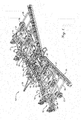
Figure 1 is a left, top isometric view of one exemplary tillage machine utilizing a walking beam and lift system arrangement in accordance with the principles of the present invention, the tillage machine being shown in a field working position; -
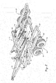
Fig. 2 is an enlarged left, rear, top isometric view of the machine ofFig. 1 with the wing sections removed to more clearly reveal the triple axle walking beam wheel assemblies utilized with the centre section of the machine; -
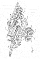
Fig.3 is an isometric view of the machine similar toFig.2 but illustrating the machine in a raised position in which the abutment on the wheel arm has come into engagement with a stop on the walking beam wheel assembly; -
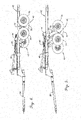
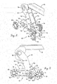
Fig.4 is a side elevational view of the centre section of the machine in a field working position corresponding toFigs. 1 and2 ; -
Fig. 5 is a side elevational view of the centre section in a raised position corresponding toFig. 3 ; -
Fig. 6 is a fragmentary, top plan view of the centre section in a raised position corresponding toFigs. 3 and5 ; -
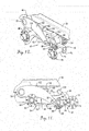
Fig. 7 is a fragmentary, left, rear, exploded isometric view of the left triple axle walking beam assembly and associated structure of the centre section; -
Fig. 8 is an enlarged, fragmentary, left rear isometric view of the wheel assembly inFig.7 with wheels removed and the left side plate of the primary beam of the walking beam assembly removed to reveal details of construction, the machine being illustrated in a raised position corresponding toFigs. 3 ,5 and7 ; -
Fig. 9 is a fragmentary side elevational view of the wheel assembly in theFig. 8 position with wheels and the left side plate of the primary beam removed to reveal details of construction; -
Fig. 10 is a fragmentary, left rear isometric view of the wheel assembly similar toFig. 8 but with the machine in its lowered, field working position corresponding toFigs. 15 2, and 4 ; -
Fig. 11 is is a fragmentary side elevational view of the wheel assembly with the machine in the lowered position ofFig. 10 ; and -
Fig. 12 is a fragmentary, left elevational view of the wheel assembly when the machine is in a raised position, illustrating the manner in which the primary and secondary beams of the walking beam assembly can oscillate independently of one another. - The present invention is susceptible of embodiment in many different forms. While the drawings illustrate and the specification describes certain preferred embodiments of the invention, it is to be understood that such disclosure is by way of example only.
- The
tillage machine 10 illustrated inFig. 1 has been selected as but one of many different possible examples of machines with which the present invention may be utilized. In the illustrated embodiment,machine 10 is a five-section folding machine comprising acentre sections 12, twoinner wing sections centre section 12, and twoouter wing sections inner wing sections wing sections inner wing sections wing lift cylinders outer wing sections inner sections wing lift cylinders discs 26 for working the soil as the machine is advanced across a field. Atongue 28 projects forwardly fromcentre section 12 for hitching the machine to a towing vehicle (not shown). - Each section has its own frame or
chassis 30 to which the tillage tools of that section are attached. Each section also has its own undercarriage for supporting thechassis 30 during field operations and, in the case of the undercarriage ofcentre section 12, supporting the load of essentially the entire machine during transport whenwing sections outer wing sections wheel assembly 32, while in the case ofinner wing sections wheel assembly 34.Wheel assemblies crank arm 36 associated with each wingsection wheel assembly wheel lift cylinder 38 to raise orlower chassis 30 in order to control the depth of penetration of thetillage tools 26. On the other hand, the pair of wheel assemblies 40 and 42 forcentre section 12 are triple axle walking beam wheel assemblies in accordance with the principles of the present invention. These twowheel assemblies crank arms 44 that are in turn operated bylift cylinders 46 to raise and lowerchassis 30 ofcentre section 12 simultaneously with raising and lowering ofchassis 30 of thewing sections - As illustrated particularly in
Figs. 7 and8 , and usingassembly 40 as an example of the construction and operation of both triple axle walkingbeam wheel assemblies wheel assembly 40 is mounted on thechassis 30 by awheel arm 48 having an upper end that is fixed to a transverse torque tube 50 (Fig. 2 , for example) rotatably supported onchassis 30. Upstandingcrank arm 44 is likewise fixed totorque tube 50 such that whenhydraulic cylinder 46 is actuated,crank arm 44 rotatestorque tube 50, which in turnswings wheel arm 48 up and down about the longitudinal axis oftorque tube 50.Wheel assembly 40 is pivotally mounted on the lower end ofwheel arm 48 by atransverse pivot 52. -
Wheel assembly 40 includes a primary fore-and-aft walking beam 54 and a secondary fore-and-aft walking beam 56.Pivot pin 52 attachesprimary beam 54 towheel arm 48 at a point intermediate the opposite front andrear ends primary beam 54. In this way,primary beam 54 can rock in opposite up and down directions about the axis defined bypivot pin 52. - At the
front end 58 ofprimary beam 54, anaxle 62 projects laterally outwardly therefrom to rotatably support a front, outboard ground-engaging wheel 64 via ahub 66. At itsrear end 60, theprimary beam 54 is provided with anotherpivot pin 68 that pivotally attachessecondary beam 56 toprimary beam 54 such thatsecondary beam 56 can rock in opposite up and down directions about the axis defined bypivot pin 68.Pivot pin 68 is located intermediate afront end 70 and arear end 72 ofsecondary beam 56. At therear end 72 ofsecondary beam 56, anaxle 74 projects laterally outwardly therefrom and rotatably supports an outboard ground-engaging wheel 76 via ahub 78. At thefront end 70 ofsecondary beam 56, anaxle 80 projects laterally inwardly fromsecondary beam 56 to rotatably support an inboard, ground-engaging wheel 82 via ahub 84. It will be noted that outboard ground-engaging wheels engaging wheel 82 is disposed inboard ofwheels primary beam 54 andsecondary beam 56. -
Primary beam 54 is a fabricated structure having a pair of laterally spaced apart,opposite side plates Plates bottom plates side plates primary beam 54.Front axle 62 penetrates into the interior ofprimary beam 54 as illustrated inFigs. 7 and8 and is rigidly affixed to both top andbottom plates side plates Fig. 8 , asleeve 94spans side plates opposite ends primary beam 54 to serve as a means for journalingpivot pin 52. Top andbottom plates sleeve 94 such that the space betweenside plates sleeve 94 is largely open so as to provide operating clearance for thefront end 70 ofsecondary beam 56, which is received between the rear end portions ofside plates - As illustrated in
Fig. 9 , for example,inboard side plate 88 has a downwardlyopening notch 96 that provides operating clearance forfront axle 80 ofsecondary beam 56 assecondary beam 56 rocks up and down about the axis ofpivot pin 68. An inverted, L-shaped bracket 98 supports a block-like stop 100 that projects upwardly and forwardly frombracket 98 to protrude above the upper extremity ofprimary beam 54. Preferably, although not necessarily,stop 100 is constructed from a resilient material such as a suitable elastomeric substance. One suitable stop is commercially available from McMaster-Carr Supply Company of Princeton, New Jersey as an SBR heavy duty rubber guard having a durometer hardness of 60A-75A, part number 21685TI 3. -
Wheel arm 48 has a pair of laterally spaced apartside plates primary beam 54 and are coupled withpivot pin 52 on the outside faces ofside plates like abutment 106 is captured between and rigidly secured toside plates lower face 108 generally faces the upper surface ofstop 100. As will hereinafter be described in further detail,abutment 106 is disposed to come into force- transmitting engagement withstop 100 whenwheel arm 48 has been swung downwardly relative tochassis 30 by a predetermined amount. A downwardly openingnotch 1 10 is provided in theoutboard side plate 102 so as to clearfront axle 62 ofprimary beam 54 whenwheel arm 48 is fully raised relative tochassis 30 as illustrated, for example, inFigs. 10 and 11 . - As
machine 10 travels through the field in a lowered working position as illustrated inFigs. 1 and2 , for example, the triple axle walkingbeam wheel assemblies centre section 12, to limit the depth of penetration of thetillage tools 26, and to smooth out the ride of the centre section as undulations and obstacles are encountered in the field. Of course, wingsection wheel assemblies wing sections -
Fig. 12 , which happens to show thewheel assembly 40 in a fully lowered position whereinchassis 30 is fully raised, illustrates the type of oscillating rocking action that is available by theprimary beam 54 andsecondary beam 56 of the tripleaxle wheel assemblies Primary beam 54 can rock up and down aboutpivot 52 asfront wheel 64 encounters rises and falls, whilesecondary beam 56 can itself pivot up and down aboutpivot 68 as rises and falls are encountered byrear wheel 76 andinboard wheel 82. Thus, the ride is smoothed out while increased load capacity is obtained through the provision of three axles instead of two as in a conventional double axle walking beam assembly. - When the machine is in a lowered, field working position, the
abutment 106 with eachwheel arm 48 is spaced substantially forwardly fromstop 100 as illustrated, for example inFigs. 10 and 11 . However, when the operator comes to the end of a pass and turns around to start the next pass in the opposite direction, he will normally raise the implement so that alltillage tools 26 are out of the ground during the turn. All sections of the machine are raised simultaneously, but focusing particularly oncentre section 12, it will be seen that aswheel arms 48 are rotated downwardly by theiractuating cylinders 46, thewheel assemblies Figs. 9 and11 wherein thepivot 52 inFig. 9 is spaced considerably further forwardly than inFig. 11 . Thus, without the provision of the special weight transfer feature provided byabutment 106 and stop 100, the machine might tend to become "tail heavy", which encourages the front end oftongue 28 to slam up against the hitch bar of the towing tractor, jarring the machine and the operator. Obviously, this can be damaging to the equipment and physically hard on the operator. - Accordingly, in accordance with the present invention, after each
wheel arm 48 is swung downwardly relative tochassis 30 by a predetermined amount,abutment 106 engages stop 100, at which pointprimary beam 54 becomes locked against any further downward swinging movement of its front end relative towheel arm 48. Thus, continued downward movement ofwheel arm 48 in a clockwise direction beyond that illustrated inFig. 9 , for example, causes the front end ofprimary beam 54, and thus also frontfront wheel 64, to slightly lift up, lightening the load onfront wheel 64 and transferring it towheels secondary beam 56. This has the effect of tipping the machine forwardly aboutrear wheels tongue 28 against the tractor. Consequently, the "tail-heavy" condition is averted, as is damage to the equipment and wear and tear on the operator. Preferably, as noted above, stop 100 is a resilient cushion so that engagement of the latter withabutment 106 is not a jarring engagement and there is a measure of relief provided by the yieldability ofstop 100. - It is contemplated that for over-the-road travel,
machine 10 will not be raised to its fullest extent, i.e., to such a condition that a significant amount of the weight of the machine would be transferred fromfront wheels 64 ofwheel assemblies rear wheels centre section 12 whenwing sections lift cylinders 46 have been fully extended to fully raise the machine, suitable mechanical cylinder stops, not shown but well known to those skilled in the art, will be placed upon thecylinders 46 to enable them to retract only a certain distance before the mechanical stops prevent further such retraction. At that point, the load is borne by the cylinder stops, andabutment 106 has separated sufficiently fromstop 100 as to engagefront wheel 64 of eachwheel assembly rear wheels - It will be noted that the inboard location of each
third wheel 82 ofwheel assemblies inboard wheels 82 to ride on slightly higher surfaces than theoutboard wheels secondary beam 56 which can rotate slightly in a clockwise direction viewing the figures as necessary to permitinboard wheel 82 to ride slightly higher than theoutboard wheel 76. If need be,primary beam 54 can also rotate slightly counter clockwise to accommodate such action. Regardless, eachprimary beam 54 andsecondary beam 56 is free to oscillate as necessary to walk over irregularities in the road surface and smooth out the ride of the machine.
Claims (4)
- A tillage machine (10) comprising:a frame (30) having tillage tools supported thereon;at least one wheel arm (48) pivotally attached to the frame (30) for up and down swinging movement relative to the frame about a first transverse axis;a walking beam assembly (40) including a primary beam (54) and at least pair of ground-engaging wheels (64, 76) rotatably coupled to the beam at front and rear ends (58,60) of the beam,said walking beam assembly (40) being pivotally attached to the wheel arm (48) for up and down rocking movement relative to the wheel arm (48) about a second transverse axis;a hydraulic lift cylinder (46) operably connected between the frame (30) and the wheel arm for swinging the wheel arm up and down relative to the frame to raise andlower the frame relative to the ground;characterised in that an abutment (106) is provided on said wheel arm (48) disposed to engage a stop (100) on the beam (54) in response to a predetermined amount of downward swinging of the wheel arm relative to the frame (30), said abutment and stop being operable when mutually interengaged to cause weight transfer from said first ground-engaging wheel (64) to said second ground-engaging wheel (76) as said wheel arm swings downwardly beyond said predetermined amount.
- A tillage machine (10) as claimed in Claim 1; wherein said stop (100) is resilient.
- A tillage machine (10) as claimed in Claim 1 or 2, wherein the wheel arm (48) comprises a pair of laterally spaced apart side plates (102,104) whose lower ends straddle primary beam 54, the abutment (106) being captured between and rigidly secured to side plates (102,104).
- A tillage machine (10) according to any preceding claim, wherein said walking beam assembly (40) further includes a secondary beam (56) having a pair of front and rear ends (70,72), said secondary beam being pivotally attached to the rear end (60) of said primary beam (54) intermediate said front and rear ends (70,72) of the secondary beam (56) for up and down rocking movement of the secondary beam (56) relative to the primary beam (54) about a third transverse axis, said second ground engaging wheel (76) being rotatably attached to the rear end (72) of said secondary beam (56), said secondary beam having a third ground-engaging wheel (82) rotatably attached thereto at said front end (70) of the secondary beam (56).
Applications Claiming Priority (2)
| Application Number | Priority Date | Filing Date | Title |
|---|---|---|---|
| US12/423,386 US8261845B2 (en) | 2009-04-14 | 2009-04-14 | Walking beam assembly and lift system for tillage implements |
| EP10717746.1A EP2418930B1 (en) | 2009-04-14 | 2010-03-26 | Walking beam assembly for tillage implements |
Related Parent Applications (2)
| Application Number | Title | Priority Date | Filing Date |
|---|---|---|---|
| EP10717746.1A Division EP2418930B1 (en) | 2009-04-14 | 2010-03-26 | Walking beam assembly for tillage implements |
| EP10717746.1 Division | 2010-03-26 |
Publications (2)
| Publication Number | Publication Date |
|---|---|
| EP2604103A1 true EP2604103A1 (en) | 2013-06-19 |
| EP2604103B1 EP2604103B1 (en) | 2015-10-07 |
Family
ID=42562468
Family Applications (2)
| Application Number | Title | Priority Date | Filing Date |
|---|---|---|---|
| EP12196286.4A Active EP2604103B1 (en) | 2009-04-14 | 2010-03-26 | Lift system for tillage implements |
| EP10717746.1A Active EP2418930B1 (en) | 2009-04-14 | 2010-03-26 | Walking beam assembly for tillage implements |
Family Applications After (1)
| Application Number | Title | Priority Date | Filing Date |
|---|---|---|---|
| EP10717746.1A Active EP2418930B1 (en) | 2009-04-14 | 2010-03-26 | Walking beam assembly for tillage implements |
Country Status (5)
| Country | Link |
|---|---|
| US (1) | US8261845B2 (en) |
| EP (2) | EP2604103B1 (en) |
| BR (1) | BRPI1014452B1 (en) |
| PL (1) | PL2418930T3 (en) |
| WO (1) | WO2010119316A2 (en) |
Cited By (1)
| Publication number | Priority date | Publication date | Assignee | Title |
|---|---|---|---|---|
| WO2017058032A1 (en) * | 2015-09-30 | 2017-04-06 | Eagleton Ip Technology Limited | Improved vehicle |
Families Citing this family (17)
| Publication number | Priority date | Publication date | Assignee | Title |
|---|---|---|---|---|
| WO2011032216A1 (en) * | 2009-09-16 | 2011-03-24 | David Catford | Drop deck trailer |
| RU2014124722A (en) * | 2013-08-21 | 2015-12-27 | СиЭнЭйч ИНДАСТРИАЛ АМЕРИКА ЭлЭлСи | ONE-POINT DEPTH MANAGEMENT UNIT FOR AGRICULTURAL SOIL PROCESSING TOOLS |
| US9930823B2 (en) * | 2014-11-21 | 2018-04-03 | Bourgault Industries Ltd. | Reducing wheel forces on a field surface |
| CA2876456A1 (en) * | 2015-01-07 | 2016-07-07 | Ashley Sawatsky | Split walking beams for raising and lowering respective sides of a vehicle or implement frame to control a tilt angle or height thereof |
| DE102015100273A1 (en) * | 2015-01-09 | 2016-07-14 | Lemken Gmbh & Co. Kg | Agricultural implement with auxiliary landing gear |
| US10064322B2 (en) * | 2015-09-23 | 2018-09-04 | Deere & Company | Compact tillage implement with independent rank adjustment |
| WO2017172690A1 (en) * | 2016-03-28 | 2017-10-05 | Kinze Manufacturing, Inc. | Mechanical cylinder synchronizer |
| CN107416068A (en) * | 2017-06-28 | 2017-12-01 | 石河子市光大农机有限公司 | The four wheel mechanism of machine of working soil |
| US11104389B2 (en) | 2018-03-31 | 2021-08-31 | Jeffrey William Ash | Clamping system |
| US10744831B2 (en) | 2018-10-15 | 2020-08-18 | The Toro Company | Walking axle for a spreader sprayer machine |
| US11122732B2 (en) | 2018-10-17 | 2021-09-21 | The Toro Company | Fertilizer distribution metering system and method |
| DE202018106264U1 (en) * | 2018-11-02 | 2018-11-19 | Pöttinger Landtechnik Gmbh | Agricultural implement |
| US20200215866A1 (en) * | 2019-01-08 | 2020-07-09 | Liftmaster Ltd. | Multi-lifting-tandems suspension |
| SE543953C2 (en) * | 2019-10-24 | 2021-10-05 | Vaederstad Holding Ab | Agricultural implements and procedure for handling agricultural implements |
| US11419255B2 (en) | 2019-11-04 | 2022-08-23 | Cnh Industrial America Llc | Wheel carrier system |
| US12171150B2 (en) * | 2021-06-10 | 2024-12-24 | Raymond Zimmerman | Shank mounting for tillage implement |
| JP7686313B1 (en) * | 2024-06-21 | 2025-06-02 | 株式会社トーイングネット | Mechanism for expanding and contracting side walls of trailer bed for transporting vehicles |
Citations (5)
| Publication number | Priority date | Publication date | Assignee | Title |
|---|---|---|---|---|
| US3450074A (en) * | 1967-02-01 | 1969-06-17 | Agri Tek Inc | Seed planter for depositing fine seeds at controlled depth |
| GB2056238A (en) * | 1979-07-21 | 1981-03-18 | Amazonen Werke Dreyer H | Seed drill |
| US4974684A (en) | 1990-02-26 | 1990-12-04 | Deere & Company | Walking beam retainer |
| GB2285779A (en) * | 1994-01-19 | 1995-07-26 | Avraham Levi | Tandem axle suspension |
| EP1974596A1 (en) * | 2007-03-26 | 2008-10-01 | Horsch Maschinen GmbH | Seed coulter assembly |
Family Cites Families (24)
| Publication number | Priority date | Publication date | Assignee | Title |
|---|---|---|---|---|
| US2458091A (en) * | 1945-07-06 | 1949-01-04 | John S Moore | Disk harrow hitch locking means |
| US2493023A (en) * | 1945-11-28 | 1950-01-03 | Robert W Pointer | Resilient oscillating axle suspension |
| US2611309A (en) * | 1946-09-23 | 1952-09-23 | Joel A Crain | Grape vineyard cultivator |
| US2743936A (en) * | 1953-10-02 | 1956-05-01 | Henry W Bigge | Variable width load carrier |
| US3253838A (en) | 1963-10-18 | 1966-05-31 | Albert F Hickman | Triple axle suspension for vehicles |
| DE1555708A1 (en) * | 1964-06-20 | 1970-01-08 | Jostein Hatten | Underframe for vehicles |
| US3262715A (en) * | 1964-08-21 | 1966-07-26 | Paul D Abbott | Vehicle having selectively fixed or floating steerable wheels |
| US3369823A (en) * | 1966-04-01 | 1968-02-20 | Tomen Daniel | Trailer |
| US3467408A (en) * | 1967-04-20 | 1969-09-16 | Emil Louis Regalia | Heavy duty truck trailer |
| US3447621A (en) | 1967-08-15 | 1969-06-03 | Katrak Vehicle Co | Triple walking beam suspension and drive assembly for track laying vehicles |
| US4407381A (en) | 1977-05-23 | 1983-10-04 | Standard Manufacturing Company, Inc. | Undercarriage for adverse terrain vehicles |
| US4108249A (en) * | 1977-07-01 | 1978-08-22 | Chromalloy Farm And Industrial Equipment Co. | Agricultural implement with constant frame attitude maintaining mechanism |
| US4139065A (en) | 1977-09-28 | 1979-02-13 | Dynamics Corporation Of America | Transport wheel assembly for implements |
| US4227711A (en) * | 1978-09-25 | 1980-10-14 | The United States Of America As Represented By The Secretary Of The Navy | 3-Axle walking beam suspension |
| US4572311A (en) | 1982-08-20 | 1986-02-25 | Oswald Norman D | Walking beam arrangement for adverse terrain vehicle |
| DE8901707U1 (en) | 1989-02-14 | 1989-11-16 | Alois Pöttinger Landmaschinen-Gesellschaft mbH, 8900 Augsburg | Agricultural harvesting machine with a feeler and support wheel device |
| US4941676A (en) | 1989-03-03 | 1990-07-17 | Kopczynski John F | All-terrain vehicle |
| US5186485A (en) | 1991-04-01 | 1993-02-16 | Paccar, Inc. | Vehicle suspension |
| US5277257A (en) * | 1992-10-05 | 1994-01-11 | Deere & Company | Depth control mechanism for an implement |
| US5655615A (en) * | 1994-01-06 | 1997-08-12 | Mick; Jeffrey | Wheeled vehicle for distributing agricultural materials in fields having uneven terrain |
| US5427184A (en) * | 1994-04-07 | 1995-06-27 | Deere & Company | Crank adjusted depth control for an implement |
| CA2208114C (en) * | 1996-06-24 | 2000-12-19 | Douglas Line | Common depth control adjustment for a ground opener |
| US6003616A (en) * | 1998-03-20 | 1999-12-21 | Deere & Company | Wheel arm assembly interchangeable between walking beam and straight tandem configurations |
| NL1029351C2 (en) * | 2005-06-28 | 2007-01-02 | Lely Entpr Ag | Haymaking machine and machine. |
-
2009
- 2009-04-14 US US12/423,386 patent/US8261845B2/en active Active
-
2010
- 2010-03-26 WO PCT/IB2010/000695 patent/WO2010119316A2/en not_active Ceased
- 2010-03-26 BR BRPI1014452A patent/BRPI1014452B1/en active IP Right Grant
- 2010-03-26 PL PL10717746T patent/PL2418930T3/en unknown
- 2010-03-26 EP EP12196286.4A patent/EP2604103B1/en active Active
- 2010-03-26 EP EP10717746.1A patent/EP2418930B1/en active Active
Patent Citations (5)
| Publication number | Priority date | Publication date | Assignee | Title |
|---|---|---|---|---|
| US3450074A (en) * | 1967-02-01 | 1969-06-17 | Agri Tek Inc | Seed planter for depositing fine seeds at controlled depth |
| GB2056238A (en) * | 1979-07-21 | 1981-03-18 | Amazonen Werke Dreyer H | Seed drill |
| US4974684A (en) | 1990-02-26 | 1990-12-04 | Deere & Company | Walking beam retainer |
| GB2285779A (en) * | 1994-01-19 | 1995-07-26 | Avraham Levi | Tandem axle suspension |
| EP1974596A1 (en) * | 2007-03-26 | 2008-10-01 | Horsch Maschinen GmbH | Seed coulter assembly |
Cited By (1)
| Publication number | Priority date | Publication date | Assignee | Title |
|---|---|---|---|---|
| WO2017058032A1 (en) * | 2015-09-30 | 2017-04-06 | Eagleton Ip Technology Limited | Improved vehicle |
Also Published As
| Publication number | Publication date |
|---|---|
| EP2418930B1 (en) | 2013-06-05 |
| BRPI1014452A2 (en) | 2016-04-05 |
| PL2418930T3 (en) | 2013-11-29 |
| US20100258325A1 (en) | 2010-10-14 |
| EP2604103B1 (en) | 2015-10-07 |
| EP2418930A2 (en) | 2012-02-22 |
| WO2010119316A2 (en) | 2010-10-21 |
| US8261845B2 (en) | 2012-09-11 |
| WO2010119316A3 (en) | 2011-01-13 |
| BRPI1014452B1 (en) | 2018-10-16 |
Similar Documents
| Publication | Publication Date | Title |
|---|---|---|
| EP2604103B1 (en) | Lift system for tillage implements | |
| EP3847078B1 (en) | Track system | |
| US6561283B2 (en) | Frame support for tillage implement | |
| CA2873595C (en) | Forestry machine | |
| RU2671148C2 (en) | Soil cultivation implement for attachment to a towing vehicle | |
| US9409458B2 (en) | Vehicle with suspension system | |
| CA1295134C (en) | Tractor mounted swather | |
| US4324417A (en) | Vehicle with bogie-mounted wheels and raising device for a pair of wheels | |
| US20070169950A1 (en) | Folding soil conditioning farm implement | |
| US4993499A (en) | Wing packer | |
| US5366336A (en) | Leveling rod assembly coupled between towed implement hitch and ground wheel axle | |
| US20020043060A1 (en) | Towed farm machine | |
| US4050522A (en) | Multi-section harrow assembly | |
| AU2016206146B2 (en) | Agricultural implement having an auxiliary chassis | |
| US4253528A (en) | Pivoting dual land wheel for a plow | |
| US7614821B2 (en) | Impact compactor | |
| US9781872B2 (en) | Tillage implement with enhanced front wheel suspension | |
| EP2141978B1 (en) | Device for frontmounting of an implement on a vehicle | |
| US2356600A (en) | Pusher mechanism for tractors | |
| US2177864A (en) | Semicarrier land leveler | |
| AU2005239641B2 (en) | Blade motion reduction | |
| JP2586313Y2 (en) | Leveling mechanism of lawn mower | |
| JP2000253736A (en) | Crop transport vehicles | |
| WO2005072368A2 (en) | Landfill compactor | |
| NZ257409A (en) | Self loading earthmoving scraper with bowl having curved floor and retractable apron |
Legal Events
| Date | Code | Title | Description |
|---|---|---|---|
| PUAI | Public reference made under article 153(3) epc to a published international application that has entered the european phase |
Free format text: ORIGINAL CODE: 0009012 |
|
| AC | Divisional application: reference to earlier application |
Ref document number: 2418930 Country of ref document: EP Kind code of ref document: P |
|
| AK | Designated contracting states |
Kind code of ref document: A1 Designated state(s): AT BE BG CH CY CZ DE DK EE ES FI FR GB GR HR HU IE IS IT LI LT LU LV MC MK MT NL NO PL PT RO SE SI SK SM TR |
|
| 17P | Request for examination filed |
Effective date: 20131219 |
|
| RBV | Designated contracting states (corrected) |
Designated state(s): AT BE BG CH CY CZ DE DK EE ES FI FR GB GR HR HU IE IS IT LI LT LU LV MC MK MT NL NO PL PT RO SE SI SK SM TR |
|
| GRAP | Despatch of communication of intention to grant a patent |
Free format text: ORIGINAL CODE: EPIDOSNIGR1 |
|
| INTG | Intention to grant announced |
Effective date: 20150508 |
|
| GRAS | Grant fee paid |
Free format text: ORIGINAL CODE: EPIDOSNIGR3 |
|
| GRAA | (expected) grant |
Free format text: ORIGINAL CODE: 0009210 |
|
| AC | Divisional application: reference to earlier application |
Ref document number: 2418930 Country of ref document: EP Kind code of ref document: P |
|
| AK | Designated contracting states |
Kind code of ref document: B1 Designated state(s): AT BE BG CH CY CZ DE DK EE ES FI FR GB GR HR HU IE IS IT LI LT LU LV MC MK MT NL NO PL PT RO SE SI SK SM TR |
|
| REG | Reference to a national code |
Ref country code: GB Ref legal event code: FG4D |
|
| REG | Reference to a national code |
Ref country code: AT Ref legal event code: REF Ref document number: 753104 Country of ref document: AT Kind code of ref document: T Effective date: 20151015 Ref country code: CH Ref legal event code: EP |
|
| REG | Reference to a national code |
Ref country code: IE Ref legal event code: FG4D |
|
| REG | Reference to a national code |
Ref country code: DE Ref legal event code: R096 Ref document number: 602010028152 Country of ref document: DE |
|
| REG | Reference to a national code |
Ref country code: NL Ref legal event code: MP Effective date: 20151007 |
|
| REG | Reference to a national code |
Ref country code: AT Ref legal event code: MK05 Ref document number: 753104 Country of ref document: AT Kind code of ref document: T Effective date: 20151007 |
|
| REG | Reference to a national code |
Ref country code: LT Ref legal event code: MG4D |
|
| REG | Reference to a national code |
Ref country code: FR Ref legal event code: PLFP Year of fee payment: 7 |
|
| PG25 | Lapsed in a contracting state [announced via postgrant information from national office to epo] |
Ref country code: LT Free format text: LAPSE BECAUSE OF FAILURE TO SUBMIT A TRANSLATION OF THE DESCRIPTION OR TO PAY THE FEE WITHIN THE PRESCRIBED TIME-LIMIT Effective date: 20151007 Ref country code: IS Free format text: LAPSE BECAUSE OF FAILURE TO SUBMIT A TRANSLATION OF THE DESCRIPTION OR TO PAY THE FEE WITHIN THE PRESCRIBED TIME-LIMIT Effective date: 20160207 Ref country code: ES Free format text: LAPSE BECAUSE OF FAILURE TO SUBMIT A TRANSLATION OF THE DESCRIPTION OR TO PAY THE FEE WITHIN THE PRESCRIBED TIME-LIMIT Effective date: 20151007 Ref country code: HR Free format text: LAPSE BECAUSE OF FAILURE TO SUBMIT A TRANSLATION OF THE DESCRIPTION OR TO PAY THE FEE WITHIN THE PRESCRIBED TIME-LIMIT Effective date: 20151007 Ref country code: IT Free format text: LAPSE BECAUSE OF FAILURE TO SUBMIT A TRANSLATION OF THE DESCRIPTION OR TO PAY THE FEE WITHIN THE PRESCRIBED TIME-LIMIT Effective date: 20151007 Ref country code: NO Free format text: LAPSE BECAUSE OF FAILURE TO SUBMIT A TRANSLATION OF THE DESCRIPTION OR TO PAY THE FEE WITHIN THE PRESCRIBED TIME-LIMIT Effective date: 20160107 Ref country code: NL Free format text: LAPSE BECAUSE OF FAILURE TO SUBMIT A TRANSLATION OF THE DESCRIPTION OR TO PAY THE FEE WITHIN THE PRESCRIBED TIME-LIMIT Effective date: 20151007 |
|
| PG25 | Lapsed in a contracting state [announced via postgrant information from national office to epo] |
Ref country code: LV Free format text: LAPSE BECAUSE OF FAILURE TO SUBMIT A TRANSLATION OF THE DESCRIPTION OR TO PAY THE FEE WITHIN THE PRESCRIBED TIME-LIMIT Effective date: 20151007 Ref country code: PT Free format text: LAPSE BECAUSE OF FAILURE TO SUBMIT A TRANSLATION OF THE DESCRIPTION OR TO PAY THE FEE WITHIN THE PRESCRIBED TIME-LIMIT Effective date: 20160208 Ref country code: GR Free format text: LAPSE BECAUSE OF FAILURE TO SUBMIT A TRANSLATION OF THE DESCRIPTION OR TO PAY THE FEE WITHIN THE PRESCRIBED TIME-LIMIT Effective date: 20160108 Ref country code: PL Free format text: LAPSE BECAUSE OF FAILURE TO SUBMIT A TRANSLATION OF THE DESCRIPTION OR TO PAY THE FEE WITHIN THE PRESCRIBED TIME-LIMIT Effective date: 20151007 Ref country code: SE Free format text: LAPSE BECAUSE OF FAILURE TO SUBMIT A TRANSLATION OF THE DESCRIPTION OR TO PAY THE FEE WITHIN THE PRESCRIBED TIME-LIMIT Effective date: 20151007 Ref country code: FI Free format text: LAPSE BECAUSE OF FAILURE TO SUBMIT A TRANSLATION OF THE DESCRIPTION OR TO PAY THE FEE WITHIN THE PRESCRIBED TIME-LIMIT Effective date: 20151007 Ref country code: AT Free format text: LAPSE BECAUSE OF FAILURE TO SUBMIT A TRANSLATION OF THE DESCRIPTION OR TO PAY THE FEE WITHIN THE PRESCRIBED TIME-LIMIT Effective date: 20151007 |
|
| REG | Reference to a national code |
Ref country code: DE Ref legal event code: R097 Ref document number: 602010028152 Country of ref document: DE |
|
| PG25 | Lapsed in a contracting state [announced via postgrant information from national office to epo] |
Ref country code: CZ Free format text: LAPSE BECAUSE OF FAILURE TO SUBMIT A TRANSLATION OF THE DESCRIPTION OR TO PAY THE FEE WITHIN THE PRESCRIBED TIME-LIMIT Effective date: 20151007 |
|
| PLBE | No opposition filed within time limit |
Free format text: ORIGINAL CODE: 0009261 |
|
| STAA | Information on the status of an ep patent application or granted ep patent |
Free format text: STATUS: NO OPPOSITION FILED WITHIN TIME LIMIT |
|
| PG25 | Lapsed in a contracting state [announced via postgrant information from national office to epo] |
Ref country code: SK Free format text: LAPSE BECAUSE OF FAILURE TO SUBMIT A TRANSLATION OF THE DESCRIPTION OR TO PAY THE FEE WITHIN THE PRESCRIBED TIME-LIMIT Effective date: 20151007 Ref country code: SM Free format text: LAPSE BECAUSE OF FAILURE TO SUBMIT A TRANSLATION OF THE DESCRIPTION OR TO PAY THE FEE WITHIN THE PRESCRIBED TIME-LIMIT Effective date: 20151007 Ref country code: BE Free format text: LAPSE BECAUSE OF NON-PAYMENT OF DUE FEES Effective date: 20160331 Ref country code: DK Free format text: LAPSE BECAUSE OF FAILURE TO SUBMIT A TRANSLATION OF THE DESCRIPTION OR TO PAY THE FEE WITHIN THE PRESCRIBED TIME-LIMIT Effective date: 20151007 Ref country code: EE Free format text: LAPSE BECAUSE OF FAILURE TO SUBMIT A TRANSLATION OF THE DESCRIPTION OR TO PAY THE FEE WITHIN THE PRESCRIBED TIME-LIMIT Effective date: 20151007 Ref country code: RO Free format text: LAPSE BECAUSE OF FAILURE TO SUBMIT A TRANSLATION OF THE DESCRIPTION OR TO PAY THE FEE WITHIN THE PRESCRIBED TIME-LIMIT Effective date: 20151007 |
|
| 26N | No opposition filed |
Effective date: 20160708 |
|
| PG25 | Lapsed in a contracting state [announced via postgrant information from national office to epo] |
Ref country code: MC Free format text: LAPSE BECAUSE OF FAILURE TO SUBMIT A TRANSLATION OF THE DESCRIPTION OR TO PAY THE FEE WITHIN THE PRESCRIBED TIME-LIMIT Effective date: 20151007 Ref country code: LU Free format text: LAPSE BECAUSE OF FAILURE TO SUBMIT A TRANSLATION OF THE DESCRIPTION OR TO PAY THE FEE WITHIN THE PRESCRIBED TIME-LIMIT Effective date: 20160326 |
|
| REG | Reference to a national code |
Ref country code: CH Ref legal event code: PL |
|
| GBPC | Gb: european patent ceased through non-payment of renewal fee |
Effective date: 20160326 |
|
| PG25 | Lapsed in a contracting state [announced via postgrant information from national office to epo] |
Ref country code: SI Free format text: LAPSE BECAUSE OF FAILURE TO SUBMIT A TRANSLATION OF THE DESCRIPTION OR TO PAY THE FEE WITHIN THE PRESCRIBED TIME-LIMIT Effective date: 20151007 |
|
| REG | Reference to a national code |
Ref country code: IE Ref legal event code: MM4A |
|
| PG25 | Lapsed in a contracting state [announced via postgrant information from national office to epo] |
Ref country code: BE Free format text: LAPSE BECAUSE OF FAILURE TO SUBMIT A TRANSLATION OF THE DESCRIPTION OR TO PAY THE FEE WITHIN THE PRESCRIBED TIME-LIMIT Effective date: 20151007 |
|
| PG25 | Lapsed in a contracting state [announced via postgrant information from national office to epo] |
Ref country code: GB Free format text: LAPSE BECAUSE OF NON-PAYMENT OF DUE FEES Effective date: 20160326 Ref country code: IE Free format text: LAPSE BECAUSE OF NON-PAYMENT OF DUE FEES Effective date: 20160326 Ref country code: LI Free format text: LAPSE BECAUSE OF NON-PAYMENT OF DUE FEES Effective date: 20160331 Ref country code: CH Free format text: LAPSE BECAUSE OF NON-PAYMENT OF DUE FEES Effective date: 20160331 |
|
| REG | Reference to a national code |
Ref country code: FR Ref legal event code: PLFP Year of fee payment: 8 |
|
| PG25 | Lapsed in a contracting state [announced via postgrant information from national office to epo] |
Ref country code: MT Free format text: LAPSE BECAUSE OF FAILURE TO SUBMIT A TRANSLATION OF THE DESCRIPTION OR TO PAY THE FEE WITHIN THE PRESCRIBED TIME-LIMIT Effective date: 20151007 |
|
| REG | Reference to a national code |
Ref country code: FR Ref legal event code: PLFP Year of fee payment: 9 |
|
| PG25 | Lapsed in a contracting state [announced via postgrant information from national office to epo] |
Ref country code: CY Free format text: LAPSE BECAUSE OF FAILURE TO SUBMIT A TRANSLATION OF THE DESCRIPTION OR TO PAY THE FEE WITHIN THE PRESCRIBED TIME-LIMIT Effective date: 20151007 Ref country code: HU Free format text: LAPSE BECAUSE OF FAILURE TO SUBMIT A TRANSLATION OF THE DESCRIPTION OR TO PAY THE FEE WITHIN THE PRESCRIBED TIME-LIMIT; INVALID AB INITIO Effective date: 20100326 |
|
| PG25 | Lapsed in a contracting state [announced via postgrant information from national office to epo] |
Ref country code: MK Free format text: LAPSE BECAUSE OF FAILURE TO SUBMIT A TRANSLATION OF THE DESCRIPTION OR TO PAY THE FEE WITHIN THE PRESCRIBED TIME-LIMIT Effective date: 20151007 Ref country code: TR Free format text: LAPSE BECAUSE OF FAILURE TO SUBMIT A TRANSLATION OF THE DESCRIPTION OR TO PAY THE FEE WITHIN THE PRESCRIBED TIME-LIMIT Effective date: 20151007 Ref country code: MT Free format text: LAPSE BECAUSE OF FAILURE TO SUBMIT A TRANSLATION OF THE DESCRIPTION OR TO PAY THE FEE WITHIN THE PRESCRIBED TIME-LIMIT Effective date: 20160331 |
|
| PG25 | Lapsed in a contracting state [announced via postgrant information from national office to epo] |
Ref country code: BG Free format text: LAPSE BECAUSE OF FAILURE TO SUBMIT A TRANSLATION OF THE DESCRIPTION OR TO PAY THE FEE WITHIN THE PRESCRIBED TIME-LIMIT Effective date: 20151007 |
|
| P01 | Opt-out of the competence of the unified patent court (upc) registered |
Effective date: 20230518 |
|
| PGFP | Annual fee paid to national office [announced via postgrant information from national office to epo] |
Ref country code: DE Payment date: 20250319 Year of fee payment: 16 |
|
| PGFP | Annual fee paid to national office [announced via postgrant information from national office to epo] |
Ref country code: FR Payment date: 20250325 Year of fee payment: 16 |