EP2603720B1 - Two part valve - Google Patents
Two part valve Download PDFInfo
- Publication number
- EP2603720B1 EP2603720B1 EP10744885.4A EP10744885A EP2603720B1 EP 2603720 B1 EP2603720 B1 EP 2603720B1 EP 10744885 A EP10744885 A EP 10744885A EP 2603720 B1 EP2603720 B1 EP 2603720B1
- Authority
- EP
- European Patent Office
- Prior art keywords
- valve
- valve housing
- housing portion
- handle body
- passage
- Prior art date
- Legal status (The legal status is an assumption and is not a legal conclusion. Google has not performed a legal analysis and makes no representation as to the accuracy of the status listed.)
- Active
Links
Images
Classifications
-
- F—MECHANICAL ENGINEERING; LIGHTING; HEATING; WEAPONS; BLASTING
- F16—ENGINEERING ELEMENTS AND UNITS; GENERAL MEASURES FOR PRODUCING AND MAINTAINING EFFECTIVE FUNCTIONING OF MACHINES OR INSTALLATIONS; THERMAL INSULATION IN GENERAL
- F16K—VALVES; TAPS; COCKS; ACTUATING-FLOATS; DEVICES FOR VENTING OR AERATING
- F16K27/00—Construction of housing; Use of materials therefor
- F16K27/04—Construction of housing; Use of materials therefor of sliding valves
- F16K27/048—Electromagnetically actuated valves
-
- F—MECHANICAL ENGINEERING; LIGHTING; HEATING; WEAPONS; BLASTING
- F16—ENGINEERING ELEMENTS AND UNITS; GENERAL MEASURES FOR PRODUCING AND MAINTAINING EFFECTIVE FUNCTIONING OF MACHINES OR INSTALLATIONS; THERMAL INSULATION IN GENERAL
- F16K—VALVES; TAPS; COCKS; ACTUATING-FLOATS; DEVICES FOR VENTING OR AERATING
- F16K27/00—Construction of housing; Use of materials therefor
- F16K27/04—Construction of housing; Use of materials therefor of sliding valves
- F16K27/041—Construction of housing; Use of materials therefor of sliding valves cylindrical slide valves
-
- F—MECHANICAL ENGINEERING; LIGHTING; HEATING; WEAPONS; BLASTING
- F15—FLUID-PRESSURE ACTUATORS; HYDRAULICS OR PNEUMATICS IN GENERAL
- F15B—SYSTEMS ACTING BY MEANS OF FLUIDS IN GENERAL; FLUID-PRESSURE ACTUATORS, e.g. SERVOMOTORS; DETAILS OF FLUID-PRESSURE SYSTEMS, NOT OTHERWISE PROVIDED FOR
- F15B13/00—Details of servomotor systems ; Valves for servomotor systems
- F15B13/02—Fluid distribution or supply devices characterised by their adaptation to the control of servomotors
- F15B13/06—Fluid distribution or supply devices characterised by their adaptation to the control of servomotors for use with two or more servomotors
- F15B13/08—Assemblies of units, each for the control of a single servomotor only
- F15B13/0803—Modular units
- F15B13/0832—Modular valves
- F15B13/0835—Cartridge type valves
-
- Y—GENERAL TAGGING OF NEW TECHNOLOGICAL DEVELOPMENTS; GENERAL TAGGING OF CROSS-SECTIONAL TECHNOLOGIES SPANNING OVER SEVERAL SECTIONS OF THE IPC; TECHNICAL SUBJECTS COVERED BY FORMER USPC CROSS-REFERENCE ART COLLECTIONS [XRACs] AND DIGESTS
- Y10—TECHNICAL SUBJECTS COVERED BY FORMER USPC
- Y10T—TECHNICAL SUBJECTS COVERED BY FORMER US CLASSIFICATION
- Y10T137/00—Fluid handling
- Y10T137/8593—Systems
- Y10T137/86493—Multi-way valve unit
- Y10T137/86574—Supply and exhaust
- Y10T137/86582—Pilot-actuated
- Y10T137/86614—Electric
Definitions
- the present invention relates generally to a two part valve.
- a valve includes a solenoid located on one side of a valve housing and a cartridge inserted into an opening in an opposing side of the valve housing.
- a plug is inserted into the hole to retain the cartridge in the valve housing. If the cartridge or any other internal components need to be serviced or removed, the entire valve must be removed to access the opening in the opposing side of the valve housing.
- the cartridge is positioned in the housing from a top of the valve housing.
- a lid is placed over the valve housing to enclose the cartridge, and the lid is secured in place by screws or a circlip.
- a valve according the invention is defined by the claims.
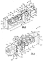
- Figures 1 , 2 and 3 illustrate a two part valve 10 that controls the flow of a fluid.
- the fluid is air.
- the valve 10 includes a first valve housing portion 12 and a second valve housing portion 14 that are separate components.
- the first valve housing portion 12 has a first length L1, and the second valve housing portion 14 has a second length L2, and L1 is greater than L2. In one example, L1 is significantly greater than L2.
- the first valve housing portion 12 includes an outer end surface 15 and an opposing inner end surface 16. When the valve 10 is assembled, the inner end surface 16 contacts an inner end surface 56 of the second valve housing portion 14.
- the inner end surface 16 includes an opening 18 that defines a passage 20 within the first valve housing portion 12.
- a cartridge 22 including a poppet/stem assembly 24 is received in the passage 20. The poppet/stem assembly 24 is moveable relative to the first valve housing portion 12 to control the flow of the fluid through the valve 10.
- a top surface 26 of the first valve housing portion 12 includes at least two apertures 28.
- the bottom surface 30 of the first valve housing portion 12 includes at least two apertures 32 aligned with the at least two apertures 28 of the top surface 26 to define a at last two passages 34 that extend through a height H1 of the first valve housing portion 12.
- the bottom surface 30 includes an inlet port 36, an outlet port 38, and an exhaust port 40.
- An inlet passage 42, an outlet passage 44, and an exhaust passage 46 are in fluid communication with the inlet port 36, the outlet port 38, and the exhaust port 40, respectively.
- the flow of the fluid through the passages 42, 44 and 46 is controlled by the position of the poppet/stem assembly 24 in the first valve housing portion 12.
- a seal 48 is located in each of the ports 36, 38 and 40. respectively, to prevent leakage of the fluid.
- the seal 48 is an o-ring.
- the inner end surface 16 also includes a plurality of holes 50 that each define a passage 51.
- a hole 50 is located in an upper corner of the inner end surface 16, and a hole 50 is located in an opposing lower corner of the inner end surface 16.
- the passages 51 each receive a pin 52 to secure the first valve housing portion 12 to the second valve housing portion 14, as described below.
- the second valve housing portion 14 includes an outer end surface 54 and the opposing inner end surface 56.
- the inner end surface 56 includes an opening 58 surround by a protruding annular rim 60 having an annular groove 62.
- a seal 64 is received in the annular groove 62.
- the seal 64 is an o-ring.
- the annular rim 60 is sized to fit within the opening 18 of the first valve housing portion 12.
- the first valve housing portion 12 includes the annular rim 60
- the second valve housing portion 14 includes the opening 18.
- the inner end surface 56 also includes a plurality of holes 66 that each define a passage 68.
- a hole 66 is located in an upper corner of the inner end surface 56, and a hole 66 is located in an opposing lower corner of the inner end surface 56.
- the holes 66 each receive the pin 52 to secure the first valve housing portion 12 against rotation related to the second valve housing portion 14.
- a magnet 72 is attached to the outer end surface 54 of the second valve housing portion 14 with a fastener 74.
- the magnet 72 includes a plurality of projections 76 that are each located and sized to be received in one of a plurality of holes (not shown) on the outer end surface 54 of the second valve housing portion 14.
- the second valve housing portion 14 can include the plurality of projections 76, and the magnet 72 can include the plurality of holes.
- a rod 80 is located in a hole (not shown) in the outer end surface 54 of the second valve housing portion 14. When the magnet 72 is actuated to actuate the valve 10, the magnet 72 moves the rod 80 to actuate a pilot 82.
- a top surface 84 of the second valve housing portion 14 includes at least one aperture 86.
- a bottom surface 88 of the second valve housing portion 14 includes at least one aperture 90 aligned with the at least one aperture 86 of the top surface 84 to define a passage 92 that extends through a height H2 of the second valve housing portion 14.
- the second valve housing portion 14 also include an opening 94 on the top surface 84 that defines a passage 96 that receives a hand operative manual release 98.
- the hand operative manual release 98 includes a cylinder 100 that is received in the passage 96.
- the cylinder 100 includes a groove 102 having a first end 104 that is closer to an upper end 106 of the cylinder 100 and a second end 108 that is closer to a lower end 110 of the cylinder 100. In one example, the groove 102 is diagonal.
- the cylinder 100 also includes an aperture 112 that engages a structure (not shown) in the second valve housing portion 14 to prevent rotation of the cylinder 100 relative to the second valve housing portion 14.
- a resilient member 114 is located in a hollow portion 117 of the cylinder 100. In one example, the resilient member 114 is a spring.
- the hand operative manual release 98 also includes a handle body 116 including an upper portion 118 and a lower portion 120, and the upper portion 118 has a larger diameter than the lower portion 120.
- the upper portion 118 includes an upper set of aligned apertures 122 near a top of the upper portion 118 of the handle body 116 and a lower set of aligned apertures 127 near a bottom of the upper portion 118 of the handle body 116.
- the lower portion 120 also includes an aperture 122.
- the resilient member 114 surrounds the lower portion 120 of the handle body 116 that is received in the hollow portion 117 of the cylinder 100. The resilient member 114 biases the handle body 116 upwardly.
- a grip rod 124 is received in the upper set of aligned apertures 122.
- a groove rod 126 is received in the lower set of aligned apertures 127 and extends into the groove 102 of the cylinder 100.
- the aperture 122 of the lower portion 120 of the hand operative manual release 98 allows for the flow of pilot air through the aperture 122 when the hand operative manual release 98 is actuated to manually actuate the valve 10.
- the cylinder 100 is received in the opening 94 on the top surface 84 of the second valve housing portion 14. The length of the groove 102 controls the degree of movement of the handle body 116.
- the bottom surface 88 also includes a pilot port 128 that is in fluid communication with pilot passages 140 of the pilot 82.
- the pilot 82 provides the pilot air intake that flows through tubes 140 to actuate the valve 10.
- the pilot 82 is actuated by the magnet 72 or the hand operative manual release 98.
- a seal 41 is located around the pilot port 128.
- the grip rod 124 is actuated by an operator. Prior to manual actuation, the groove rod 126 is located at the first end 104 of the groove 102. To manually actuate the valve 10, the grip rod 124 is pushed downwardly and rotated, compressing the resilient member 114 and rotating and translating the handle body 116 relative to the stationary cylinder 100. As the handle body 116 rotates and translates, the groove rod 126 travels in the groove 102 until the groove rod 126 contacts the second end 108 of the groove 102. Therefore, the user must both push the handle body 116 downwardly towards the valve 10 and rotate the handle body 116 to actuate the hand operative manual release 98. In one example, the grip rod 124 rotates approximately 90°. Once the grip rod 124 has rotated, the aperture 122 of the lower portion 120 of the handle body 116 is aligned with the pilot 82, allowing the flow of pilot air to move the poppet/stem assembly 24 and actuate the valve 10.
- the cartridge 22 When the valve 10 is to be assembled, the cartridge 22 is inserted into the passage 20 of the first valve housing member 12.
- the protruding annular rim 60 with the seal 64 in the annular groove 62 of the second valve housing portion 14 is inserted into the opening 18 of the inner end surface 56 of the first valve housing portion 12 until the inner end surfaces 16 and 56 contact.
- the friction of the seal 64 of the opening 18 of the inner end surface 56 of the first valve housing portion 12 retains the valve housing portions 12 and 14 together.
- the seal 64 also provides a sealing function.
- the pins 52 are received in the aligned holes 50 and 66 on the inner end surfaces 16 and 56, respectively, of the valve housing portions 12 and 14, respectively, to further provide stability and security of the valve housing portions 12 and 14 to each other.
- valve housing portions 12 and 14 are retained together before the valve 10 is mounted and also provide sealing. Once mounted, the valve housing portions 12 and 14 will not separate. Once the valve 10 is assembled, fasteners are located in the passages 34 and 92 to secure the valve 10 to the base (not shown). However, if the cartridge 22 or other internal valve components need to be accessed for replacement or service, the second valve housing portion 14 can be quickly separated from the first valve housing portion 12 to allow access to the cartridge 22 and the internal components.
- Figure 4 illustrates a normally open valve 10. Fluid flows into the inlet port 36 and exits through the outlet port 38 to perform a function.
- the valve 10 is actuated by the magnet 72 or hand operative manual release 98, pilot air flows through the passages 140 to move the poppet/stem assembly 24 of the cartridge 22, blocking the flow of fluid from the inlet port 36 to the outlet port 38. Fluid is then exhausted through the exhaust port 40.
- the pilot air supply is deactivated, the valve 10 returns to the normally open position.
- Figure 5 illustrates a normally closed valve 10. Fluid does not flow from the inlet port 36 to the outlet port 38 and is exhausted through the exhaust port 40.
- the valve 10 is actuated by the magnet 72 or the hand operative manual release 98, pilot air flows through the pilot passages 140 to move the poppet/stem assembly 24 of the cartridge 22, allowing the flow of fluid from the inlet port 36 to the outlet port 38 to perform a function.
- the valve 10 returns to the normally closed position.
Landscapes
- Engineering & Computer Science (AREA)
- General Engineering & Computer Science (AREA)
- Mechanical Engineering (AREA)
- Physics & Mathematics (AREA)
- Electromagnetism (AREA)
- Magnetically Actuated Valves (AREA)
- Valve Housings (AREA)
- Multiple-Way Valves (AREA)
- Fluid Mechanics (AREA)
- Preventing Unauthorised Actuation Of Valves (AREA)
Description
- The present invention relates generally to a two part valve.
- A valve includes a solenoid located on one side of a valve housing and a cartridge inserted into an opening in an opposing side of the valve housing. A plug is inserted into the hole to retain the cartridge in the valve housing. If the cartridge or any other internal components need to be serviced or removed, the entire valve must be removed to access the opening in the opposing side of the valve housing.
- In another valve, the cartridge is positioned in the housing from a top of the valve housing. A lid is placed over the valve housing to enclose the cartridge, and the lid is secured in place by screws or a circlip.
-
DE 10 2006 024 762 - A valve according the invention is defined by the claims.
- The features of the present invention will be best understood from the following specification and drawings.
- The various features and advantages of the invention will become apparent to those skilled in the art from the following detailed description of the currently preferred embodiment. The drawings that accompanies the detailed description can be briefly described as follows:
-
Figure 1 illustrates an isometric perspective view of a valve; -
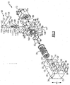
Figure 2 illustrates an exploded perspective view of the valve; -
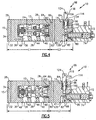
Figure 3 illustrates a bottom isometric perspective view of the valve; -
Figure 4 illustrates a cross sectional view of a normally open valve when a pilot is de-energized; and -
Figure 5 illustrates a cross sectional view of a normally closed valve when the pilot is de-energized. -
Figures 1 ,2 and3 illustrate a twopart valve 10 that controls the flow of a fluid. In one example, the fluid is air. Thevalve 10 includes a firstvalve housing portion 12 and a secondvalve housing portion 14 that are separate components. The firstvalve housing portion 12 has a first length L1, and the secondvalve housing portion 14 has a second length L2, and L1 is greater than L2. In one example, L1 is significantly greater than L2. The firstvalve housing portion 12 includes anouter end surface 15 and an opposinginner end surface 16. When thevalve 10 is assembled, theinner end surface 16 contacts an inner end surface 56 of the secondvalve housing portion 14. Theinner end surface 16 includes anopening 18 that defines apassage 20 within the firstvalve housing portion 12. Acartridge 22 including a poppet/stem assembly 24 is received in thepassage 20. The poppet/stem assembly 24 is moveable relative to the firstvalve housing portion 12 to control the flow of the fluid through thevalve 10. - A
top surface 26 of the firstvalve housing portion 12 includes at least twoapertures 28. Thebottom surface 30 of the firstvalve housing portion 12 includes at least twoapertures 32 aligned with the at least twoapertures 28 of thetop surface 26 to define a at last twopassages 34 that extend through a height H1 of the firstvalve housing portion 12. In one example, there are twopassages 34 positioned near theouter end surface 15 of the firstvalve housing portion 12. Eachpassage 34 receives a fastener (not shown) to attach thevalve 10 to a base (not shown). - The
bottom surface 30 includes aninlet port 36, anoutlet port 38, and anexhaust port 40. Aninlet passage 42, anoutlet passage 44, and anexhaust passage 46 are in fluid communication with theinlet port 36, theoutlet port 38, and theexhaust port 40, respectively. The flow of the fluid through thepassages stem assembly 24 in the firstvalve housing portion 12. Aseal 48 is located in each of theports seal 48 is an o-ring. - The
inner end surface 16 also includes a plurality ofholes 50 that each define apassage 51. In one example, ahole 50 is located in an upper corner of theinner end surface 16, and ahole 50 is located in an opposing lower corner of theinner end surface 16. Thepassages 51 each receive apin 52 to secure the firstvalve housing portion 12 to the secondvalve housing portion 14, as described below. - The second
valve housing portion 14 includes anouter end surface 54 and the opposing inner end surface 56. The inner end surface 56 includes an opening 58 surround by a protrudingannular rim 60 having anannular groove 62. Aseal 64 is received in theannular groove 62. In one example, theseal 64 is an o-ring. Theannular rim 60 is sized to fit within the opening 18 of the firstvalve housing portion 12. Alternatively, the firstvalve housing portion 12 includes theannular rim 60, and the secondvalve housing portion 14 includes theopening 18. - The inner end surface 56 also includes a plurality of
holes 66 that each define apassage 68. In one example, ahole 66 is located in an upper corner of the inner end surface 56, and ahole 66 is located in an opposing lower corner of the inner end surface 56. Theholes 66 each receive thepin 52 to secure the firstvalve housing portion 12 against rotation related to the secondvalve housing portion 14. - A
magnet 72 is attached to theouter end surface 54 of the secondvalve housing portion 14 with afastener 74. Themagnet 72 includes a plurality ofprojections 76 that are each located and sized to be received in one of a plurality of holes (not shown) on theouter end surface 54 of the secondvalve housing portion 14. Alternately, the secondvalve housing portion 14 can include the plurality ofprojections 76, and themagnet 72 can include the plurality of holes. Arod 80 is located in a hole (not shown) in theouter end surface 54 of the secondvalve housing portion 14. When themagnet 72 is actuated to actuate thevalve 10, themagnet 72 moves therod 80 to actuate apilot 82. - A
top surface 84 of the secondvalve housing portion 14 includes at least oneaperture 86. Abottom surface 88 of the secondvalve housing portion 14 includes at least oneaperture 90 aligned with the at least oneaperture 86 of thetop surface 84 to define apassage 92 that extends through a height H2 of the secondvalve housing portion 14. In one example, there are twopassages 92 positioned near theouter end surface 54 of the secondvalve housing portion 14. Eachpassage 92 receives a fastener (not shown) to attach thevalve 10 to the base (not shown). - The second
valve housing portion 14 also include anopening 94 on thetop surface 84 that defines apassage 96 that receives a hand operativemanual release 98. The hand operativemanual release 98 includes acylinder 100 that is received in thepassage 96. Thecylinder 100 includes agroove 102 having afirst end 104 that is closer to anupper end 106 of thecylinder 100 and asecond end 108 that is closer to alower end 110 of thecylinder 100. In one example, thegroove 102 is diagonal. Thecylinder 100 also includes anaperture 112 that engages a structure (not shown) in the secondvalve housing portion 14 to prevent rotation of thecylinder 100 relative to the secondvalve housing portion 14. Aresilient member 114 is located in ahollow portion 117 of thecylinder 100. In one example, theresilient member 114 is a spring. - The hand operative
manual release 98 also includes ahandle body 116 including anupper portion 118 and alower portion 120, and theupper portion 118 has a larger diameter than thelower portion 120. Theupper portion 118 includes an upper set of alignedapertures 122 near a top of theupper portion 118 of thehandle body 116 and a lower set of alignedapertures 127 near a bottom of theupper portion 118 of thehandle body 116. Thelower portion 120 also includes anaperture 122. Theresilient member 114 surrounds thelower portion 120 of thehandle body 116 that is received in thehollow portion 117 of thecylinder 100. Theresilient member 114 biases thehandle body 116 upwardly. - A
grip rod 124 is received in the upper set of alignedapertures 122. Agroove rod 126 is received in the lower set of alignedapertures 127 and extends into thegroove 102 of thecylinder 100. Theaperture 122 of thelower portion 120 of the hand operativemanual release 98 allows for the flow of pilot air through theaperture 122 when the hand operativemanual release 98 is actuated to manually actuate thevalve 10. Thecylinder 100 is received in theopening 94 on thetop surface 84 of the secondvalve housing portion 14. The length of thegroove 102 controls the degree of movement of thehandle body 116. - The
bottom surface 88 also includes apilot port 128 that is in fluid communication withpilot passages 140 of thepilot 82. Thepilot 82 provides the pilot air intake that flows throughtubes 140 to actuate thevalve 10. Thepilot 82 is actuated by themagnet 72 or the hand operativemanual release 98. Aseal 41 is located around thepilot port 128. - If manual actuation is needed, the
grip rod 124 is actuated by an operator. Prior to manual actuation, thegroove rod 126 is located at thefirst end 104 of thegroove 102. To manually actuate thevalve 10, thegrip rod 124 is pushed downwardly and rotated, compressing theresilient member 114 and rotating and translating thehandle body 116 relative to thestationary cylinder 100. As thehandle body 116 rotates and translates, thegroove rod 126 travels in thegroove 102 until thegroove rod 126 contacts thesecond end 108 of thegroove 102. Therefore, the user must both push thehandle body 116 downwardly towards thevalve 10 and rotate thehandle body 116 to actuate the hand operativemanual release 98. In one example, thegrip rod 124 rotates approximately 90°. Once thegrip rod 124 has rotated, theaperture 122 of thelower portion 120 of thehandle body 116 is aligned with thepilot 82, allowing the flow of pilot air to move the poppet/stem assembly 24 and actuate thevalve 10. - When the
valve 10 is to be assembled, thecartridge 22 is inserted into thepassage 20 of the firstvalve housing member 12. The protrudingannular rim 60 with theseal 64 in theannular groove 62 of the secondvalve housing portion 14 is inserted into theopening 18 of the inner end surface 56 of the firstvalve housing portion 12 until the inner end surfaces 16 and 56 contact. The friction of theseal 64 of theopening 18 of the inner end surface 56 of the firstvalve housing portion 12 retains thevalve housing portions seal 64 also provides a sealing function. Thepins 52 are received in the alignedholes valve housing portions valve housing portions seal 64 and thepins 52 ensures that thevalve housing portions valve 10 is mounted and also provide sealing. Once mounted, thevalve housing portions valve 10 is assembled, fasteners are located in thepassages valve 10 to the base (not shown). However, if thecartridge 22 or other internal valve components need to be accessed for replacement or service, the secondvalve housing portion 14 can be quickly separated from the firstvalve housing portion 12 to allow access to thecartridge 22 and the internal components. -
Figure 4 illustrates a normallyopen valve 10. Fluid flows into theinlet port 36 and exits through theoutlet port 38 to perform a function. When thevalve 10 is actuated by themagnet 72 or hand operativemanual release 98, pilot air flows through thepassages 140 to move the poppet/stem assembly 24 of thecartridge 22, blocking the flow of fluid from theinlet port 36 to theoutlet port 38. Fluid is then exhausted through theexhaust port 40. When the pilot air supply is deactivated, thevalve 10 returns to the normally open position. -
Figure 5 illustrates a normally closedvalve 10. Fluid does not flow from theinlet port 36 to theoutlet port 38 and is exhausted through theexhaust port 40. When thevalve 10 is actuated by themagnet 72 or the hand operativemanual release 98, pilot air flows through thepilot passages 140 to move the poppet/stem assembly 24 of thecartridge 22, allowing the flow of fluid from theinlet port 36 to theoutlet port 38 to perform a function. When the pilot air supply is deactivated, thevalve 10 returns to the normally closed position. - The foregoing description is only exemplary of the principles of the invention. Many modifications and variations of the present invention are possible in light of the above teachings. The preferred embodiments of this invention have been disclosed, however, so that one of ordinary skill in the art would recognize that certain modifications would come within the scope of this invention. It is, therefore, to be understood that within the scope of the appended claims, the invention may be practiced otherwise than as specifically described. For that reason the following claims should be studied to determine the true scope and content of this invention.
Claims (10)
- A valve (10) comprising:a first valve housing portion (12) including an inner end surface (16) having one of an opening (18) and a protruding rim (60) with an annular groove (62); anda second valve housing portion (14) including an inner end surface (56) having the other of the opening (18) and the protruding annular rim (60) with the annular groove (62), wherein a seal (64) is received in the annular groove (62),wherein the first valve housing portion (12) and the second valve housing portion (14) are separate components attached together to define a valve housing, and the protruding annular rim (60) including the seal (64) is received in the opening (18) to define the valve housing,characterized in thatthe first valve housing portion (12) includes at least two first passages (34) extending from a top surface (26) to a bottom surface (30) of the first valve housing portion (12) but not through the second valve housing portion (14), and at least two first fasteners are received in the at least two first passages (34) to retain the first valve housing portion (12) to a base, andthe second valve housing portion (14) includes at least one second passage (92) extending from a top surface (84) to a bottom surface (88) of the second valve housing portion (14) but not through the first valve housing portion (12), and at least one second fastener is received in the at least one second passage (92) to retain the second valve housing portion (14) to the base.
- The valve (10) as recited in claim 1 wherein the first valve housing portion (12) includes the opening (18) that defines a passage (20), and a cartridge (22) including a poppet is received in the passage (20).
- The valve (10) as recited in claim 2 wherein the first valve housing portion (12) includes an inlet port (36), an outlet port (38), and an exhaust port (40), and the poppet moves relative to the first valve housing portion (12) to control flow of a fluid through the valve (10).
- The valve (10) as recited in claim 1 wherein the second valve housing portion (14) includes a pilot (82) which actuates the valve (10).
- The valve (10) as recited in claim 1 wherein the inner end surface (16) of the first valve housing portion (12) includes a first aperture and the inner end surface (56) of the second valve housing portion (14) includes a second aperture that aligns with the first aperture when the valve (10) is assembled, and a fastener is received in the aligned apertures.
- The valve (10) as recited in claim 4 wherein the second valve housing portion (14) includes an outer end surface (54), and a magnet (72) that actuates the pilot (82) to actuate the valve (10) is attached to the outer end surface (54).
- The valve (10) as recited in claim 4 or 6 wherein the second valve housing portion (14) includes an upper surface (84) including an opening (86) that defines a passage (92), and a manual release (98) for the pilot (82) is located in the passage (92).
- The valve (10) as recited in claim 7 wherein the manual release (98) includes a cylinder (100) having a hollow interior (117) and a diagonal groove (102) on an exterior surface of the cylinder (100), the diagonal groove (102) having a first end (104) and a second end (108), the manual release (98) including a resilient member (114) received in the hollow interior (117) and a handle body (116) having an upper portion (118) and a lower portion (120),
wherein the resilient member (114) surrounds the lower portion (120) of the handle body (116) and biases the handle body (116) upwardly, and a groove rod (126) is received in the upper portion (118) of the handle body (116) and the diagonal groove (102) of the cylinder (100), and
wherein the handle body (116) is moveable to manually actuate the pilot (82) by pressing the handle body (116) downwardly and rotating the handle body (116), and the groove rod (126) slides from the first end to the second end of the cylinder (100) as the handle body (116) is rotated relative to the cylinder (100). - The valve (10) as recited in claim 8 wherein the groove rod (126) moves in the diagonal groove (102) as the handle body (116) is moved, and a length of the diagonal groove (102) controls an amount of movement of the handle body (116), and when an aperture (122) in the handle body (116) is aligned with a pilot passage (140), pilot air flows through pilot passages (140) and manually actuates the valve (10).
- The valve (10) as recited in any of the previous claims wherein
the first valve housing portion (12) includes the opening (18) defining the passage (20), the first valve housing portion (12) including the inlet port (36), the outlet port (38), and the exhaust port (40),
a cartridge (22) including a poppet is received in the passage (20), wherein the poppet moves relative to the first valve housing portion (12) to control flow of a fluid through the valve (10); and
the second valve housing portion (14) includes the protruding annular rim (60).
Applications Claiming Priority (1)
| Application Number | Priority Date | Filing Date | Title |
|---|---|---|---|
| PCT/EP2010/004885 WO2012019622A1 (en) | 2010-08-10 | 2010-08-10 | Two part valve |
Publications (2)
| Publication Number | Publication Date |
|---|---|
| EP2603720A1 EP2603720A1 (en) | 2013-06-19 |
| EP2603720B1 true EP2603720B1 (en) | 2016-04-13 |
Family
ID=43807010
Family Applications (1)
| Application Number | Title | Priority Date | Filing Date |
|---|---|---|---|
| EP10744885.4A Active EP2603720B1 (en) | 2010-08-10 | 2010-08-10 | Two part valve |
Country Status (5)
| Country | Link |
|---|---|
| US (1) | US9909678B2 (en) |
| EP (1) | EP2603720B1 (en) |
| JP (1) | JP5763192B2 (en) |
| CN (1) | CN103097788B (en) |
| WO (1) | WO2012019622A1 (en) |
Families Citing this family (1)
| Publication number | Priority date | Publication date | Assignee | Title |
|---|---|---|---|---|
| JP7244259B2 (en) * | 2018-11-20 | 2023-03-22 | 株式会社Taiyo | solenoid valve |
Family Cites Families (28)
| Publication number | Priority date | Publication date | Assignee | Title |
|---|---|---|---|---|
| US2861592A (en) * | 1954-03-11 | 1958-11-25 | John E Collins | Plunger valve with solenoid pilot and manual override valve mechanism |
| US2955617A (en) * | 1955-11-09 | 1960-10-11 | Int Basic Economy Corp | Plunger valve with two solenoidactuated pilot valves |
| US2993510A (en) * | 1956-11-28 | 1961-07-25 | Int Basic Economy Corp | Fluid control valve |
| DE1401296A1 (en) * | 1958-07-15 | 1968-10-24 | Erich Herion | Multi-way valve with auxiliary valve control, especially multi-way solenoid valve |
| US3540480A (en) * | 1968-06-07 | 1970-11-17 | Parker Hannifin Corp | Manual control for solenoid valve |
| US3938555A (en) * | 1974-03-21 | 1976-02-17 | International Basic Economy Corporation | Valve override apparatus |
| US4046165A (en) * | 1975-06-04 | 1977-09-06 | Ibec Industries, Inc. | Valve-positioning apparatus |
| DE2752938C2 (en) * | 1977-11-26 | 1985-06-20 | Bürkert GmbH, 7118 Ingelfingen | Control valve assembly for dental equipment |
| US4207917A (en) * | 1978-09-27 | 1980-06-17 | Wabco Westinghouse Gmbh | Hand-operation device for solenoid valves |
| IT1144393B (en) * | 1981-07-17 | 1986-10-29 | Fiat Auto Spa | FLOW REGULATING VALVE FOR HYDRAULIC CIRCUITS |
| US4620567A (en) * | 1983-08-29 | 1986-11-04 | American Standard Inc. | Solenoid-operated valve |
| US5836335A (en) * | 1991-08-19 | 1998-11-17 | Fluid Power Industries, Inc. | Proportional pressure control valve |
| DK170121B1 (en) * | 1993-06-04 | 1995-05-29 | Man B & W Diesel Gmbh | Sliding valve and large two stroke internal combustion engine |
| JP3959563B2 (en) * | 1997-10-20 | 2007-08-15 | Smc株式会社 | Pilot type switching valve |
| US6065487A (en) * | 1998-11-23 | 2000-05-23 | Amot Controls Corp. | Valve with different configurations for different uses |
| JP2000283118A (en) * | 1999-03-31 | 2000-10-13 | Smc Corp | Fluid pressure apparatus with misoperation prevention cover |
| JP3280003B2 (en) | 1999-10-18 | 2002-04-30 | エスエムシー株式会社 | Supply / exhaust device for solenoid valve assembly |
| US6644340B2 (en) * | 2001-04-04 | 2003-11-11 | Henrik Rokkjaer | Corrosive resistant liquid extraction apparatus |
| JP2003065453A (en) * | 2001-08-28 | 2003-03-05 | Smc Corp | Body for valve and its manufacturing method |
| ES2355615T3 (en) | 2002-04-26 | 2011-03-29 | Millipore Corporation | DISPOSABLE STERILE FLUID TRANSFER DEVICE. |
| DE10334206B4 (en) * | 2003-07-26 | 2008-09-11 | Festo Ag & Co | valve unit |
| DE10354269B4 (en) * | 2003-11-20 | 2006-02-02 | Festo Ag & Co. | valve unit |
| JP4919002B2 (en) * | 2005-06-20 | 2012-04-18 | Smc株式会社 | Manifold solenoid valve assembly |
| DE102006024762B4 (en) * | 2006-05-27 | 2010-12-02 | Festo Ag & Co. Kg | Valve |
| CN100417852C (en) * | 2006-09-08 | 2008-09-10 | 济南高仕机械制造有限公司 | Convertible valve body |
| WO2008081331A2 (en) | 2006-12-29 | 2008-07-10 | Sinomab Bioscience Limited | Enhancing the level of antibody expression by framework re-engineering |
| DE102007007645B3 (en) * | 2007-02-16 | 2008-10-16 | Festo Ag & Co. Kg | Valve i.e. impulse valve, has retaining device assigned to end sections of valve slider in such manner that valve slider switchable between two switching positions is detachably lockable in both switching positions |
| DE102012006681A1 (en) * | 2012-03-30 | 2013-10-02 | Hydac Fluidtechnik Gmbh | Valve, in particular pilot-operated proportional pressure control valve |
-
2010
- 2010-08-10 US US13/814,829 patent/US9909678B2/en active Active
- 2010-08-10 JP JP2013523494A patent/JP5763192B2/en active Active
- 2010-08-10 EP EP10744885.4A patent/EP2603720B1/en active Active
- 2010-08-10 WO PCT/EP2010/004885 patent/WO2012019622A1/en not_active Ceased
- 2010-08-10 CN CN201080068542.2A patent/CN103097788B/en active Active
Also Published As
| Publication number | Publication date |
|---|---|
| JP2013533446A (en) | 2013-08-22 |
| WO2012019622A8 (en) | 2012-04-26 |
| JP5763192B2 (en) | 2015-08-12 |
| CN103097788B (en) | 2015-10-14 |
| US20130207009A1 (en) | 2013-08-15 |
| WO2012019622A1 (en) | 2012-02-16 |
| EP2603720A1 (en) | 2013-06-19 |
| US9909678B2 (en) | 2018-03-06 |
| CN103097788A (en) | 2013-05-08 |
Similar Documents
| Publication | Publication Date | Title |
|---|---|---|
| EP2359722B1 (en) | Leak proof drinking lid with pressure relief | |
| US6655316B2 (en) | Visual position indicator for valves with linear moving valve stem | |
| CA2601074A1 (en) | Fluid flow control device | |
| US20090184272A1 (en) | Normally closed pneumatic diaphragm valve with mechanical override with lockout | |
| CA2598905A1 (en) | Valve and actuator assemblies | |
| US20100012699A1 (en) | Control mechanism for Pneumatic Nail Guns | |
| CA2323857A1 (en) | Pilot-operated relief valve | |
| EP3147594A2 (en) | Pilot operated valve | |
| EP1715230B1 (en) | Fluid controller | |
| EP2603720B1 (en) | Two part valve | |
| GB2472568A (en) | A perfume bottle spray head assembly comprising a rotary shut-off control disc | |
| US7131629B2 (en) | Composite valve for gas supply system | |
| JP2013508648A (en) | Fluid operated valves and installation tools | |
| US6938874B2 (en) | Spanner for a ball valve | |
| EP1382893A1 (en) | Ball valve for hydraulic circuits | |
| US6997434B2 (en) | Twist cam valve | |
| US11067194B2 (en) | Combination valve | |
| AT379118B (en) | TAP LOCK FOR LARGE CONTAINERS, IN PARTICULAR DRUM PIPE | |
| JP2022173931A (en) | Operation valve | |
| CN116409539B (en) | Bottle electromagnetic valve | |
| KR200290737Y1 (en) | Valve for a gas can | |
| KR200399891Y1 (en) | Vertical cock for regulating flow of gas for cooking stove | |
| JP3624067B2 (en) | Pilot valve | |
| JPH0469315B2 (en) | ||
| JPS5826685Y2 (en) | Selection valve for gas extinguishing |
Legal Events
| Date | Code | Title | Description |
|---|---|---|---|
| PUAI | Public reference made under article 153(3) epc to a published international application that has entered the european phase |
Free format text: ORIGINAL CODE: 0009012 |
|
| 17P | Request for examination filed |
Effective date: 20130212 |
|
| AK | Designated contracting states |
Kind code of ref document: A1 Designated state(s): AL AT BE BG CH CY CZ DE DK EE ES FI FR GB GR HR HU IE IS IT LI LT LU LV MC MK MT NL NO PL PT RO SE SI SK SM TR |
|
| DAX | Request for extension of the european patent (deleted) | ||
| 17Q | First examination report despatched |
Effective date: 20150414 |
|
| GRAP | Despatch of communication of intention to grant a patent |
Free format text: ORIGINAL CODE: EPIDOSNIGR1 |
|
| INTG | Intention to grant announced |
Effective date: 20151210 |
|
| GRAS | Grant fee paid |
Free format text: ORIGINAL CODE: EPIDOSNIGR3 |
|
| GRAA | (expected) grant |
Free format text: ORIGINAL CODE: 0009210 |
|
| AK | Designated contracting states |
Kind code of ref document: B1 Designated state(s): AL AT BE BG CH CY CZ DE DK EE ES FI FR GB GR HR HU IE IS IT LI LT LU LV MC MK MT NL NO PL PT RO SE SI SK SM TR |
|
| REG | Reference to a national code |
Ref country code: GB Ref legal event code: FG4D |
|
| REG | Reference to a national code |
Ref country code: AT Ref legal event code: REF Ref document number: 790517 Country of ref document: AT Kind code of ref document: T Effective date: 20160415 Ref country code: CH Ref legal event code: EP |
|
| REG | Reference to a national code |
Ref country code: IE Ref legal event code: FG4D |
|
| REG | Reference to a national code |
Ref country code: DE Ref legal event code: R096 Ref document number: 602010032251 Country of ref document: DE |
|
| REG | Reference to a national code |
Ref country code: SE Ref legal event code: TRGR |
|
| REG | Reference to a national code |
Ref country code: LT Ref legal event code: MG4D |
|
| REG | Reference to a national code |
Ref country code: AT Ref legal event code: MK05 Ref document number: 790517 Country of ref document: AT Kind code of ref document: T Effective date: 20160413 |
|
| REG | Reference to a national code |
Ref country code: NL Ref legal event code: MP Effective date: 20160413 |
|
| PG25 | Lapsed in a contracting state [announced via postgrant information from national office to epo] |
Ref country code: NL Free format text: LAPSE BECAUSE OF FAILURE TO SUBMIT A TRANSLATION OF THE DESCRIPTION OR TO PAY THE FEE WITHIN THE PRESCRIBED TIME-LIMIT Effective date: 20160413 Ref country code: NO Free format text: LAPSE BECAUSE OF FAILURE TO SUBMIT A TRANSLATION OF THE DESCRIPTION OR TO PAY THE FEE WITHIN THE PRESCRIBED TIME-LIMIT Effective date: 20160713 Ref country code: LT Free format text: LAPSE BECAUSE OF FAILURE TO SUBMIT A TRANSLATION OF THE DESCRIPTION OR TO PAY THE FEE WITHIN THE PRESCRIBED TIME-LIMIT Effective date: 20160413 Ref country code: FI Free format text: LAPSE BECAUSE OF FAILURE TO SUBMIT A TRANSLATION OF THE DESCRIPTION OR TO PAY THE FEE WITHIN THE PRESCRIBED TIME-LIMIT Effective date: 20160413 Ref country code: PL Free format text: LAPSE BECAUSE OF FAILURE TO SUBMIT A TRANSLATION OF THE DESCRIPTION OR TO PAY THE FEE WITHIN THE PRESCRIBED TIME-LIMIT Effective date: 20160413 |
|
| PG25 | Lapsed in a contracting state [announced via postgrant information from national office to epo] |
Ref country code: ES Free format text: LAPSE BECAUSE OF FAILURE TO SUBMIT A TRANSLATION OF THE DESCRIPTION OR TO PAY THE FEE WITHIN THE PRESCRIBED TIME-LIMIT Effective date: 20160413 Ref country code: LV Free format text: LAPSE BECAUSE OF FAILURE TO SUBMIT A TRANSLATION OF THE DESCRIPTION OR TO PAY THE FEE WITHIN THE PRESCRIBED TIME-LIMIT Effective date: 20160413 Ref country code: GR Free format text: LAPSE BECAUSE OF FAILURE TO SUBMIT A TRANSLATION OF THE DESCRIPTION OR TO PAY THE FEE WITHIN THE PRESCRIBED TIME-LIMIT Effective date: 20160714 Ref country code: PT Free format text: LAPSE BECAUSE OF FAILURE TO SUBMIT A TRANSLATION OF THE DESCRIPTION OR TO PAY THE FEE WITHIN THE PRESCRIBED TIME-LIMIT Effective date: 20160816 Ref country code: HR Free format text: LAPSE BECAUSE OF FAILURE TO SUBMIT A TRANSLATION OF THE DESCRIPTION OR TO PAY THE FEE WITHIN THE PRESCRIBED TIME-LIMIT Effective date: 20160413 Ref country code: AT Free format text: LAPSE BECAUSE OF FAILURE TO SUBMIT A TRANSLATION OF THE DESCRIPTION OR TO PAY THE FEE WITHIN THE PRESCRIBED TIME-LIMIT Effective date: 20160413 |
|
| PG25 | Lapsed in a contracting state [announced via postgrant information from national office to epo] |
Ref country code: BE Free format text: LAPSE BECAUSE OF FAILURE TO SUBMIT A TRANSLATION OF THE DESCRIPTION OR TO PAY THE FEE WITHIN THE PRESCRIBED TIME-LIMIT Effective date: 20160413 |
|
| REG | Reference to a national code |
Ref country code: DE Ref legal event code: R097 Ref document number: 602010032251 Country of ref document: DE |
|
| PG25 | Lapsed in a contracting state [announced via postgrant information from national office to epo] |
Ref country code: EE Free format text: LAPSE BECAUSE OF FAILURE TO SUBMIT A TRANSLATION OF THE DESCRIPTION OR TO PAY THE FEE WITHIN THE PRESCRIBED TIME-LIMIT Effective date: 20160413 Ref country code: SK Free format text: LAPSE BECAUSE OF FAILURE TO SUBMIT A TRANSLATION OF THE DESCRIPTION OR TO PAY THE FEE WITHIN THE PRESCRIBED TIME-LIMIT Effective date: 20160413 Ref country code: DK Free format text: LAPSE BECAUSE OF FAILURE TO SUBMIT A TRANSLATION OF THE DESCRIPTION OR TO PAY THE FEE WITHIN THE PRESCRIBED TIME-LIMIT Effective date: 20160413 Ref country code: RO Free format text: LAPSE BECAUSE OF FAILURE TO SUBMIT A TRANSLATION OF THE DESCRIPTION OR TO PAY THE FEE WITHIN THE PRESCRIBED TIME-LIMIT Effective date: 20160413 |
|
| PLBE | No opposition filed within time limit |
Free format text: ORIGINAL CODE: 0009261 |
|
| STAA | Information on the status of an ep patent application or granted ep patent |
Free format text: STATUS: NO OPPOSITION FILED WITHIN TIME LIMIT |
|
| PG25 | Lapsed in a contracting state [announced via postgrant information from national office to epo] |
Ref country code: SM Free format text: LAPSE BECAUSE OF FAILURE TO SUBMIT A TRANSLATION OF THE DESCRIPTION OR TO PAY THE FEE WITHIN THE PRESCRIBED TIME-LIMIT Effective date: 20160413 |
|
| 26N | No opposition filed |
Effective date: 20170116 |
|
| PG25 | Lapsed in a contracting state [announced via postgrant information from national office to epo] |
Ref country code: MC Free format text: LAPSE BECAUSE OF FAILURE TO SUBMIT A TRANSLATION OF THE DESCRIPTION OR TO PAY THE FEE WITHIN THE PRESCRIBED TIME-LIMIT Effective date: 20160413 |
|
| REG | Reference to a national code |
Ref country code: CH Ref legal event code: PL |
|
| GBPC | Gb: european patent ceased through non-payment of renewal fee |
Effective date: 20160810 |
|
| PG25 | Lapsed in a contracting state [announced via postgrant information from national office to epo] |
Ref country code: CH Free format text: LAPSE BECAUSE OF NON-PAYMENT OF DUE FEES Effective date: 20160831 Ref country code: LI Free format text: LAPSE BECAUSE OF NON-PAYMENT OF DUE FEES Effective date: 20160831 |
|
| REG | Reference to a national code |
Ref country code: FR Ref legal event code: ST Effective date: 20170428 |
|
| PG25 | Lapsed in a contracting state [announced via postgrant information from national office to epo] |
Ref country code: SI Free format text: LAPSE BECAUSE OF FAILURE TO SUBMIT A TRANSLATION OF THE DESCRIPTION OR TO PAY THE FEE WITHIN THE PRESCRIBED TIME-LIMIT Effective date: 20160413 |
|
| REG | Reference to a national code |
Ref country code: IE Ref legal event code: MM4A |
|
| PG25 | Lapsed in a contracting state [announced via postgrant information from national office to epo] |
Ref country code: FR Free format text: LAPSE BECAUSE OF NON-PAYMENT OF DUE FEES Effective date: 20160831 Ref country code: IE Free format text: LAPSE BECAUSE OF NON-PAYMENT OF DUE FEES Effective date: 20160810 Ref country code: GB Free format text: LAPSE BECAUSE OF NON-PAYMENT OF DUE FEES Effective date: 20160810 |
|
| PG25 | Lapsed in a contracting state [announced via postgrant information from national office to epo] |
Ref country code: LU Free format text: LAPSE BECAUSE OF NON-PAYMENT OF DUE FEES Effective date: 20160810 |
|
| PG25 | Lapsed in a contracting state [announced via postgrant information from national office to epo] |
Ref country code: HU Free format text: LAPSE BECAUSE OF FAILURE TO SUBMIT A TRANSLATION OF THE DESCRIPTION OR TO PAY THE FEE WITHIN THE PRESCRIBED TIME-LIMIT; INVALID AB INITIO Effective date: 20100810 Ref country code: CY Free format text: LAPSE BECAUSE OF FAILURE TO SUBMIT A TRANSLATION OF THE DESCRIPTION OR TO PAY THE FEE WITHIN THE PRESCRIBED TIME-LIMIT Effective date: 20160413 |
|
| PG25 | Lapsed in a contracting state [announced via postgrant information from national office to epo] |
Ref country code: IS Free format text: LAPSE BECAUSE OF FAILURE TO SUBMIT A TRANSLATION OF THE DESCRIPTION OR TO PAY THE FEE WITHIN THE PRESCRIBED TIME-LIMIT Effective date: 20160413 Ref country code: TR Free format text: LAPSE BECAUSE OF FAILURE TO SUBMIT A TRANSLATION OF THE DESCRIPTION OR TO PAY THE FEE WITHIN THE PRESCRIBED TIME-LIMIT Effective date: 20160413 Ref country code: MK Free format text: LAPSE BECAUSE OF FAILURE TO SUBMIT A TRANSLATION OF THE DESCRIPTION OR TO PAY THE FEE WITHIN THE PRESCRIBED TIME-LIMIT Effective date: 20160413 Ref country code: MT Free format text: LAPSE BECAUSE OF NON-PAYMENT OF DUE FEES Effective date: 20160831 |
|
| PG25 | Lapsed in a contracting state [announced via postgrant information from national office to epo] |
Ref country code: BG Free format text: LAPSE BECAUSE OF FAILURE TO SUBMIT A TRANSLATION OF THE DESCRIPTION OR TO PAY THE FEE WITHIN THE PRESCRIBED TIME-LIMIT Effective date: 20160413 |
|
| PG25 | Lapsed in a contracting state [announced via postgrant information from national office to epo] |
Ref country code: AL Free format text: LAPSE BECAUSE OF FAILURE TO SUBMIT A TRANSLATION OF THE DESCRIPTION OR TO PAY THE FEE WITHIN THE PRESCRIBED TIME-LIMIT Effective date: 20160413 |
|
| PGFP | Annual fee paid to national office [announced via postgrant information from national office to epo] |
Ref country code: SE Payment date: 20250626 Year of fee payment: 16 |
|
| PGFP | Annual fee paid to national office [announced via postgrant information from national office to epo] |
Ref country code: DE Payment date: 20250624 Year of fee payment: 16 |
|
| PGFP | Annual fee paid to national office [announced via postgrant information from national office to epo] |
Ref country code: IT Payment date: 20250722 Year of fee payment: 16 |
|
| PGFP | Annual fee paid to national office [announced via postgrant information from national office to epo] |
Ref country code: CZ Payment date: 20250723 Year of fee payment: 16 |