EP2602800B1 - Oil transformer - Google Patents
Oil transformer Download PDFInfo
- Publication number
- EP2602800B1 EP2602800B1 EP11009670.8A EP11009670A EP2602800B1 EP 2602800 B1 EP2602800 B1 EP 2602800B1 EP 11009670 A EP11009670 A EP 11009670A EP 2602800 B1 EP2602800 B1 EP 2602800B1
- Authority
- EP
- European Patent Office
- Prior art keywords
- oil
- transformer
- oil chamber
- coil
- opening
- Prior art date
- Legal status (The legal status is an assumption and is not a legal conclusion. Google has not performed a legal analysis and makes no representation as to the accuracy of the status listed.)
- Active
Links
Images


Classifications
-
- H—ELECTRICITY
- H01—ELECTRIC ELEMENTS
- H01F—MAGNETS; INDUCTANCES; TRANSFORMERS; SELECTION OF MATERIALS FOR THEIR MAGNETIC PROPERTIES
- H01F27/00—Details of transformers or inductances, in general
- H01F27/08—Cooling; Ventilating
- H01F27/10—Liquid cooling
- H01F27/12—Oil cooling
-
- H—ELECTRICITY
- H01—ELECTRIC ELEMENTS
- H01F—MAGNETS; INDUCTANCES; TRANSFORMERS; SELECTION OF MATERIALS FOR THEIR MAGNETIC PROPERTIES
- H01F27/00—Details of transformers or inductances, in general
- H01F27/02—Casings
- H01F27/025—Constructional details relating to cooling
-
- H—ELECTRICITY
- H01—ELECTRIC ELEMENTS
- H01F—MAGNETS; INDUCTANCES; TRANSFORMERS; SELECTION OF MATERIALS FOR THEIR MAGNETIC PROPERTIES
- H01F27/00—Details of transformers or inductances, in general
- H01F27/28—Coils; Windings; Conductive connections
- H01F27/32—Insulating of coils, windings, or parts thereof
- H01F27/322—Insulating of coils, windings, or parts thereof the insulation forming channels for circulation of the fluid
Definitions
- the invention is related to an oil transformer, comprising a transformer vessel, a transformer core mounted therein, at least one upright hollow cylindrical transformer coil with at least one axial cooling channel arranged around a limb of the transformer core, an oil chamber arranged at an axial front side of the transformer coil, wherein at least one first opening leading from the inner chamber to the belonging front side of the transformer coil is foreseen and wherein at least one second opening is foreseen within the surrounding boundaries of the oil chamber.
- transformers in energy distribution networks of for example with a rated voltage of 110kV or 380kV are usually designed as oil transformers.
- the transformer core with its coils is arranged in an oil filled vessel, wherein the oil is on one side insulation medium and on the other side cooling medium.
- the oil circulates inbetween cooling channels through the coil windings, where heat losses are generated during operation of the transformer, and a cooling device which transfers the heat from the oil to outer environment.
- the circulation of the oil might be generated by a pump for example but also natural convection is possible.
- the transformer coil has to become mechanically strengthened to withstand the mechanical forces which occur inbetween neighbored conductor windings during short-circuit, which might cause a temporary current of for example 100kA or higher.
- a mechanical strengthening is required, wherein in radial direction the ring like arrangement of the windings around the winding axis is strong enough to withstand the belonging short-circuit forces.
- the axial forces during short-circuit might, for example, be five times higher.
- an axial clamping structure is required at both axial ends of the transformer coil, which puts an axial clamping pressure on the axial ends of the coil and which prevents a mechanical deformation of the coil in axial direction during short circuit.
- This clamping structure has to be designed in a way that an oil flow through this structure to the inner cooling channels of the transformer coil clamped therein is enabled, respectively from the inner cooling channels through the clamping structure at the opposite side of the transformer winding.
- an oil chamber is foreseen for an improved oil flow through the cooling channels of the belonging transformer coils.
- Such an oil chamber is normally disc-like shaped and placed under a belonging upright coil and is fluidicly connected with its axial cooling channels. Cooled oil is pressurized within this oil chamber, so that the oil flows up through the cooling channels to the upper axial end of the coil.
- the belonging lower coil fixture is integrated as part of a belonging oil chamber.
- an oil chamber comprises a press ring building the bottom plate of the oil chamber as well as a spacer ring, wherein additional low bordering walls are foreseen at the radial edges of the spacer ring to enable the inner chamber to withstand the pressure of the oil.
- flat perforated panels on top of the spacer ring are foreseen, which are building the top cover of the oil chamber. The purpose of the perforation is the passage of the oil from the inner oil chamber to the transformer winding.
- An example for an oil chamber is for example disclosed within the patent filing US 4424502 .
- the patent filing US 4145679 A1 is disclosing a transformer apparatus cooled and electrically insulated by a vaporizable liquid dielectric having a boiling point within the normal operating temperature range of the transformer.
- An oil containing upper space (44) is provided on the upper side of the transformer coil comprising axial cooling channels.
- Another example for a transformer with an inner cooling circuit of a liquid such as oil is disclosed within the WO 2010/102669 A1 , where upper and lower clamping bars are provided on top and bottom of the transformer coil comprising axial cooling channels. The lower bars form channel-like bodies for guiding oil therethrough.
- An oil transformer according to the present invention is defined in claim 1.
- An oil chamber as such has to be understood as inner space surrounded by boundaries respectively walls, so that an underpressure can be generated therein.
- the walls have not to be necessarily part of the oil chamber, Moreover they can also be build by walls or sides of adjacent parts.
- the oil flow through the axial cooling channels of the transformer coil is directed upwards so that - even if no pump or comparable device is foreseen for the revolution of the oil - a natural cooling circuit is realized at least as fall back solution.
- the oil is sucked of the upper axial end of the transformer coil and preferably directly fed into a cooling system by using a pump or comparable device.
- Rib-like spacer elements are foreseen within the oil chamber, which are suitable for supporting a pressure force on the transformer coil.
- the electrical current through the winding might increase temporary to a value of 100kA and higher.
- belonging forces in between adjacent windings are applied.
- the winding In radial direction the winding withstands those forces due to its circular arrangement around a (virtual) center axis.
- the structure of the transformer winding as such is not foreseen to withstand such forces, which might correspond to five time or more of the weight of the transformer coil itself.
- a coil fixture has to be foreseen at each axial end of the at least transformer coil to put a belonging pressure force thereon.
- the spacer elements which might distributed for example radially or axially, are foreseen for applying such pressure force on the upper axial end of the coil.
- the spacer elements which might distributed for example radially or axially, are foreseen for applying such pressure force on the upper axial end of the coil.
- the at least one axial cooling channel of the transformer coil and the at least one first opening are arranged at least approximately congruent concerning their cross sections.
- the oil chamber is walled on one axial side by a press ring and on the opposite side by flat perforated panels, which comprise the at least one fist opening as connection to the belonging front side of the transformer coil respectively its cooling channels.
- An approximately congruent adaptation of the belonging cross sections respectively arrangements improves once more the unhindered oil flow in between oil chamber and cooling channels.
- the at least one second opening is prolonged from the oil chamber in a tube-like manner.
- an outlet duct from the inner oil chamber through the vessel is realized, which preferably ends directly at a cooling system outside the transformer, where the oil is cooled down and fed back into the transformer vessel.
- several ducts might be realized as common collecting duct. It is furthermore possible to collect the outlet oil from the under pressure oil chamber to a larger pipe before leading it to the cooling equipment.
- the at least one second opening leads from the oil chamber directly to a cooling system outside the transformer vessel, wherein a belonging connection might be realized as collecting duct.
- a belonging connection might be realized as collecting duct.
- An external cooling system might be for example a heat exchanger with an optional air blower for example and cooling ribs.
- the oil chamber comprises a ring-shaped ground plate, the rib-like spacer elements arranged thereon and low bordering walls at the radial outer and inner edge of the ground plate wherein the ground plate is manufactured together with at least one of the other elements as a monolithic part.
- an oil chamber might be subject to a pressure force especially in the case of a short circuit.
- a certain flexural strength of the oil chamber is required to withstand.
- the flexural strength of a part is on one side dependent on the height of the part and on the other side on the characteristics of the material. If for example two identical bars are placed on each other, the total flexural strength is twice as high as for one single bar.
- the flexural strength is four times higher than for a single bar and twice as high as for the two single bars due to a quadratic dependency between thickness and flexural strength of monolithic parts.
- the spacer elements according to the invention are rib-like shaped- similar to a bar - they are also suitable for a contribution to an increased flexural strength of the oil chamber.
- an arrangement of for example 9cm press ring and 5cm spacer ring can be replaced by an at least partly monolithic oil chamber of for example 11 cm height with comparable and sufficient flexural strength.
- the method of milling is used for the manufacturing of such at least partly monolithic oil chamber. This is usually supported by CAD systems, so that a nearly unlimited variation of shapes can be realized therewith.
- the rib-like spacer elements are shaped at their side-walls in a way which differs from a plane perpendicular to the ground plate, so that the axial creeping distance along the side walls is prolonged.
- Those spacer elements also have to fulfil requirements of insulation - each front side of a transformer coil is on high voltage level during the operation of the transformer, whereas the adjacent transformer core is on earth potential. Since the overall thickness of the oil chamber is reduced in an advantageous way by the invention, it is also within the scope of the invention to gain at least the same axial insulation ability which is provided by a comparable oil chamber according to the state of the art.
- the monolithic part consists of laminated material.
- a laminated material consists of several flat layers which are glued together by using a high pressure.
- a monolithic block of extreme high stiffness is produced, which is also suitable to be milled in a desired shape.
- the monolithic block respectively part consists at least predominantly of press-board. This is a cellulose based material of a high stiffness and excellent electrical insulation capability, which is very suitable for the use in oil transformers, for example as supporting element.
- Fig. 1 shows an exemplary oil transformer 10 in a sectional drawing.
- a transformer core 14 with three limbs 28 and two exemplary upright transformer coils 16, 18 mounted thereon is arranged within a transformer vessel 12.
- the transformer vessel 12 is filled with transformer oil 30, which is on one side foreseen for purposes of electrical insulation as for cooling.
- the transformer coils 16, 18 are hollow cylindrical arranged along a belonging virtual center axis 40 and clamped inbetween a lower coil fixture 24, 26 and an upper oil chamber 20, 22, which are constructed in that way, that they can apply a pressure force on the coil, comparable to the lower coil fixtures 24, 26.
- the lower coil fixtures 24, 26 correspond in principal more or less to the oil chambers 20, 22, so they comprise a ground plate with inner opening for a transformer limb 28 and spacer elements arranged thereon, whereas flow channels 58 are formed in between adjacent spacer elements.
- Axial cooling channels 34, 36 are foreseen through the transformer coils 16, 18, so that transformer oil 30 can flow there through as indicated with the arrow 38.
- the transformer oil is heated while flowing through the cooling channels 34, 36 of the transformer and fed into the oil chambers 20, 22 afterwards.
- the second openings of the oil chambers are prolonged tubes 42, 44, which are connected with a collecting duct 48 for feeding the oil through a suction tube 50 to a cooling system 52.
- the cooling system 52 is realized as a heat exchanger with a not shown blower, which transfers the heat energy to the environment as indicated with the arrows 54.
- a not shown pump is foreseen to generate an under pressure within the oil chambers 20, 22. But also other means for generating underpressure such as radiators or such are a possible solution. Thus under pressure might also generated by pure buoyancy forces.
- the output tube 56 has to be assumed as being prolonged to belonging areas under thermo critical components such as transformer windings 16, 18 for example.
- thermo critical components such as transformer windings 16, 18 for example.
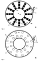
- FIG. 2 shows an exemplary third oil chamber 60 in a top view sketch.
- a ring-shaped ground plate 62 with inner opening 68 several rib-like spacer elements 72, 74, 76 are arranged in radial direction.
- the radial inner and radial outer edges of the ground plate 62 are surrounded by low bordering walls 64, 68, so that an inner chamber is formed.
- a second opening 72 is foreseen at the radial outer bordering wall as outlet for oil as indicated with the arrow 78, but the second opening might also be arranged through the top or bottom walls of the oil chamber, dependent on the available space within the transformer.
- the opening is prolonged by a tube that the oil which is sucked out of the oil chamber there through can easily fed to an external cooling system.
- Ground plate 62 and bordering walls 64, 66 are made from one monolithic part, so that the flexural stability of the oil chamber is increased in an advantageous way.
- a typical thickness of the ground plate in such a monolithic arrangement might amount 8 - 12cm, whereas the height of the spacer elements respectively the bordering walls might amount 6 - 8cm.
- FIG. 3 shows an exemplary fourth oil chamber 80 in a top view sketch.
- This chamber corresponds in principal to the chamber shown in Fig. 2 , whereas additional flat perforated panels 82 on top of the spacer ring are foreseen, which are building the top cover of the oil chamber in this sketch.
- those perforated panels When mounted on the upper axial end of a transformer coil, those perforated panels will be at the bottom of the oil chamber.
- the positioning and cross section of the perforation holes respectively first openings 86, 87, 88 are adapted to the cross section and positioning of axial cooling channels of a transformer winding to be arranged below.
- the prolonged second opening respectively the outlet duct is marked with the reference number 84.
- Those flat panels are not part of a monolithic structure, since due do reasons of manufacturing a full accessibility of the inner oil chamber has to be observed.
- Figure 4 shows an exemplary fifth oil chamber 90 as a cross section from a side view.
- a disc-like ground plate 92 with radial inner 94 and radial outer 96 bordering wall is foreseen.
- the inner area 100 of the oil chamber is formed by the bordering walls 92, 94, the ground plate 92 and flat panels 102 on top of this chamber. Spacer elements within the inner area of the oil chamber are not shown but have assumed to be present.
- Figure 5 shows an example for flexural strength of a laminated bar in a sketch 110.
- Several layers 116, 118, 120, 122 of press board are laminated to a bar.
- glue or example epoxy resin has been added during the lamination process.
- the bar is seated on two triangular supports 112, 114.
- a pressure force 124 is applied in the middle of the bar.
- the flexural strength of the laminated bar is at least as high as the flexural strength of a massive, non-laminated bar of the same size.
Landscapes
- Engineering & Computer Science (AREA)
- Power Engineering (AREA)
- Transformer Cooling (AREA)
Description
- The invention is related to an oil transformer, comprising a transformer vessel, a transformer core mounted therein, at least one upright hollow cylindrical transformer coil with at least one axial cooling channel arranged around a limb of the transformer core, an oil chamber arranged at an axial front side of the transformer coil, wherein at least one first opening leading from the inner chamber to the belonging front side of the transformer coil is foreseen and wherein at least one second opening is foreseen within the surrounding boundaries of the oil chamber.
- It is known, that transformers in energy distribution networks of for example with a rated voltage of 110kV or 380kV are usually designed as oil transformers. The transformer core with its coils is arranged in an oil filled vessel, wherein the oil is on one side insulation medium and on the other side cooling medium. Typically the oil circulates inbetween cooling channels through the coil windings, where heat losses are generated during operation of the transformer, and a cooling device which transfers the heat from the oil to outer environment. The circulation of the oil might be generated by a pump for example but also natural convection is possible.
- The transformer coil has to become mechanically strengthened to withstand the mechanical forces which occur inbetween neighbored conductor windings during short-circuit, which might cause a temporary current of for example 100kA or higher. Especially in axial direction of the transformer winding such a mechanical strengthening is required, wherein in radial direction the ring like arrangement of the windings around the winding axis is strong enough to withstand the belonging short-circuit forces. Compared with the forces caused by the weight of the transformer coil itself, the axial forces during short-circuit might, for example, be five times higher.
- Thus an axial clamping structure is required at both axial ends of the transformer coil, which puts an axial clamping pressure on the axial ends of the coil and which prevents a mechanical deformation of the coil in axial direction during short circuit. This clamping structure has to be designed in a way that an oil flow through this structure to the inner cooling channels of the transformer coil clamped therein is enabled, respectively from the inner cooling channels through the clamping structure at the opposite side of the transformer winding.
- Typically an oil chamber is foreseen for an improved oil flow through the cooling channels of the belonging transformer coils. Such an oil chamber is normally disc-like shaped and placed under a belonging upright coil and is fluidicly connected with its axial cooling channels. Cooled oil is pressurized within this oil chamber, so that the oil flows up through the cooling channels to the upper axial end of the coil. Normally the belonging lower coil fixture is integrated as part of a belonging oil chamber. Thus an oil chamber comprises a press ring building the bottom plate of the oil chamber as well as a spacer ring, wherein additional low bordering walls are foreseen at the radial edges of the spacer ring to enable the inner chamber to withstand the pressure of the oil. Furthermore flat perforated panels on top of the spacer ring are foreseen, which are building the top cover of the oil chamber. The purpose of the perforation is the passage of the oil from the inner oil chamber to the transformer winding.
- An example for an oil chamber is for example disclosed within the patent filing
US 4424502 . The patent filingUS 4145679 A1 is disclosing a transformer apparatus cooled and electrically insulated by a vaporizable liquid dielectric having a boiling point within the normal operating temperature range of the transformer. An oil containing upper space (44) is provided on the upper side of the transformer coil comprising axial cooling channels. Another example for a transformer with an inner cooling circuit of a liquid such as oil is disclosed within theWO 2010/102669 A1 , where upper and lower clamping bars are provided on top and bottom of the transformer coil comprising axial cooling channels. The lower bars form channel-like bodies for guiding oil therethrough. - Further oil transformers with axial cooling channels extending through the transformer coil are disclosed in
EP-2 04 02 73 A1 ,EP-0 61 63 41 A1 ,JP-59 15 95 12 JP-58 15 42 13 - Disadvantageously within the state of the art is that such an arrangement is on one side difficult to manufacture since the transformer winding - which might have a weight of several tons - is typically assembled directly on top of the oil chamber. On the other side the effectiveness of the cooling system is not as high, since oil is sucked of the top of the vessel, where the heated oil from the transformer coil has already been mixed with other oil.
- Based on this state of the art it is the objective of the invention to provide an oil transformer which has an improved cooling system and which is easier to assemble.
- An oil transformer according to the present invention is defined in claim 1.
- An oil chamber as such has to be understood as inner space surrounded by boundaries respectively walls, so that an underpressure can be generated therein. The walls have not to be necessarily part of the oil chamber, Moreover they can also be build by walls or sides of adjacent parts.
- Thus the oil flow through the axial cooling channels of the transformer coil is directed upwards so that - even if no pump or comparable device is foreseen for the revolution of the oil - a natural cooling circuit is realized at least as fall back solution. In an advantageous manner the oil is sucked of the upper axial end of the transformer coil and preferably directly fed into a cooling system by using a pump or comparable device.
- Most of the heat losses are generated within the windings of the transformer coils. During operation of the transformer circulating oil is heated within the cooling channels of the transformer coil and fed directly afterwards to a cooling system outside the transformer. Since this oil is not mixed with other oil within the transformer vessel, which might be not as heated, the temperature of oil flowing into the cooling system is rather high. As higher the temperature difference between oil to be cooled and the environment, where the heat has to be transferred, as better is the effectiveness of the cooling system. Thus the cooling effect is increased in an advantageous way.
- Rib-like spacer elements are foreseen within the oil chamber, which are suitable for supporting a pressure force on the transformer coil. In case of a short circuit the electrical current through the winding might increase temporary to a value of 100kA and higher. Thus belonging forces in between adjacent windings are applied. In radial direction the winding withstands those forces due to its circular arrangement around a (virtual) center axis. In axial direction the structure of the transformer winding as such is not foreseen to withstand such forces, which might correspond to five time or more of the weight of the transformer coil itself. Thus a coil fixture has to be foreseen at each axial end of the at least transformer coil to put a belonging pressure force thereon. For this reason the spacer elements, which might distributed for example radially or axially, are foreseen for applying such pressure force on the upper axial end of the coil. To ensure an unhindered oil flow between oil chamber and the upper axial front side of the transformer coil, they are fluidicly connected.
- Preferably the at least one axial cooling channel of the transformer coil and the at least one first opening are arranged at least approximately congruent concerning their cross sections. Typically the oil chamber is walled on one axial side by a press ring and on the opposite side by flat perforated panels, which comprise the at least one fist opening as connection to the belonging front side of the transformer coil respectively its cooling channels. An approximately congruent adaptation of the belonging cross sections respectively arrangements improves once more the unhindered oil flow in between oil chamber and cooling channels.
- Preferably the at least one second opening is prolonged from the oil chamber in a tube-like manner. Thus an outlet duct from the inner oil chamber through the vessel is realized, which preferably ends directly at a cooling system outside the transformer, where the oil is cooled down and fed back into the transformer vessel. In case of several, especially three, transformer coils arranged within the transformer vessel, several ducts might be realized as common collecting duct. It is furthermore possible to collect the outlet oil from the under pressure oil chamber to a larger pipe before leading it to the cooling equipment.
- Preferably the at least one second opening leads from the oil chamber directly to a cooling system outside the transformer vessel, wherein a belonging connection might be realized as collecting duct. Thus the heated oil is fed to the external cooling system with its maximum temperature. An external cooling system might be for example a heat exchanger with an optional air blower for example and cooling ribs.
- Preferably the oil chamber comprises a ring-shaped ground plate, the rib-like spacer elements arranged thereon and low bordering walls at the radial outer and inner edge of the ground plate wherein the ground plate is manufactured together with at least one of the other elements as a monolithic part. As explained above, an oil chamber might be subject to a pressure force especially in the case of a short circuit. Thus a certain flexural strength of the oil chamber is required to withstand. The flexural strength of a part is on one side dependent on the height of the part and on the other side on the characteristics of the material. If for example two identical bars are placed on each other, the total flexural strength is twice as high as for one single bar. If on the other side a monolithic bar of the same material and same size is considered, the flexural strength is four times higher than for a single bar and twice as high as for the two single bars due to a quadratic dependency between thickness and flexural strength of monolithic parts.
- Since the spacer elements according to the invention are rib-like shaped- similar to a bar - they are also suitable for a contribution to an increased flexural strength of the oil chamber. Thus, an arrangement of for example 9cm press ring and 5cm spacer ring can be replaced by an at least partly monolithic oil chamber of for example 11 cm height with comparable and sufficient flexural strength. Preferably the method of milling is used for the manufacturing of such at least partly monolithic oil chamber. This is usually supported by CAD systems, so that a nearly unlimited variation of shapes can be realized therewith.
- Preferably the rib-like spacer elements are shaped at their side-walls in a way which differs from a plane perpendicular to the ground plate, so that the axial creeping distance along the side walls is prolonged. Those spacer elements also have to fulfil requirements of insulation - each front side of a transformer coil is on high voltage level during the operation of the transformer, whereas the adjacent transformer core is on earth potential. Since the overall thickness of the oil chamber is reduced in an advantageous way by the invention, it is also within the scope of the invention to gain at least the same axial insulation ability which is provided by a comparable oil chamber according to the state of the art.
- Preferably the monolithic part consists of laminated material. A laminated material consists of several flat layers which are glued together by using a high pressure. Thus a monolithic block of extreme high stiffness is produced, which is also suitable to be milled in a desired shape. According to a further aspect of the invention, the monolithic block respectively part consists at least predominantly of press-board. This is a cellulose based material of a high stiffness and excellent electrical insulation capability, which is very suitable for the use in oil transformers, for example as supporting element.
- Further advantageous embodiments of the invention are mentioned in the dependent claims.
- The invention will now be further explained by means of an exemplary embodiment and with reference to the accompanying drawings, in which:
- Figure 1
- shows an exemplary oil transformer,
- Figure 2
- shows an exemplary third oil chamber,
- Figure 3
- shows an exemplary fourth oil chamber,
- Figure 4
- shows an exemplary fifth oil chamber and
- Figure 5
- shows an example for flexural strength of a laminated bar.
-
Fig. 1 shows anexemplary oil transformer 10 in a sectional drawing. Atransformer core 14 with threelimbs 28 and two exemplary upright transformer coils 16, 18 mounted thereon is arranged within atransformer vessel 12. Thetransformer vessel 12 is filled withtransformer oil 30, which is on one side foreseen for purposes of electrical insulation as for cooling. - The transformer coils 16, 18 are hollow cylindrical arranged along a belonging
virtual center axis 40 and clamped inbetween alower coil fixture upper oil chamber lower coil fixtures lower coil fixtures oil chambers transformer limb 28 and spacer elements arranged thereon, whereasflow channels 58 are formed in between adjacent spacer elements.Axial cooling channels transformer oil 30 can flow there through as indicated with thearrow 38. Thus the transformer oil is heated while flowing through the coolingchannels oil chambers prolonged tubes duct 48 for feeding the oil through asuction tube 50 to acooling system 52. Thecooling system 52 is realized as a heat exchanger with a not shown blower, which transfers the heat energy to the environment as indicated with thearrows 54. Furthermore a not shown pump is foreseen to generate an under pressure within theoil chambers cooling system 52 it is fed back into theinner transformer vessel 12 by anoutput tube 56. - The
output tube 56 has to be assumed as being prolonged to belonging areas under thermo critical components such astransformer windings cooling system 52 is provided in those areas, which might require enforced cooling, if no radiators are used for example. -
Figure 2 shows an exemplarythird oil chamber 60 in a top view sketch. On a ring-shapedground plate 62 withinner opening 68 several rib-like spacer elements ground plate 62 are surrounded by low borderingwalls second opening 72 is foreseen at the radial outer bordering wall as outlet for oil as indicated with thearrow 78, but the second opening might also be arranged through the top or bottom walls of the oil chamber, dependent on the available space within the transformer. The opening is prolonged by a tube that the oil which is sucked out of the oil chamber there through can easily fed to an external cooling system.Ground plate 62 and borderingwalls -
Figure 3 shows an exemplaryfourth oil chamber 80 in a top view sketch. This chamber corresponds in principal to the chamber shown inFig. 2 , whereas additional flatperforated panels 82 on top of the spacer ring are foreseen, which are building the top cover of the oil chamber in this sketch. When mounted on the upper axial end of a transformer coil, those perforated panels will be at the bottom of the oil chamber. The positioning and cross section of the perforation holes respectivelyfirst openings reference number 84. Those flat panels are not part of a monolithic structure, since due do reasons of manufacturing a full accessibility of the inner oil chamber has to be observed. -
Figure 4 shows an exemplaryfifth oil chamber 90 as a cross section from a side view. Around a virtual center axis 98 a disc-like ground plate 92 with radial inner 94 and radial outer 96 bordering wall is foreseen. Theinner area 100 of the oil chamber is formed by the borderingwalls ground plate 92 andflat panels 102 on top of this chamber. Spacer elements within the inner area of the oil chamber are not shown but have assumed to be present. -
Figure 5 shows an example for flexural strength of a laminated bar in asketch 110.Several layers triangular supports pressure force 124 is applied in the middle of the bar. As lower the bowing of the bar per pressure force as higher is the flexural strength. Due to the high-strength adhesion inbetween the different layers, the flexural strength of the laminated bar is at least as high as the flexural strength of a massive, non-laminated bar of the same size. -
- 10
- exemplary oil transformer
- 12
- transformer vessel
- 14
- transformer core
- 16
- first upright hollow cylindrical transformer coil
- 18
- second upright hollow cylindrical transformer coil
- 20
- first oil chamber
- 22
- second oil chamber
- 24
- first coil fixture
- 26
- second coil fixture
- 28
- transformer limb
- 30
- transformer oil
- 32
- press support
- 34
- first axial cooling channel
- 36
- second axial cooling channel
- 38
- flow direction through cooling channel
- 40
- virtual center axis
- 42
- prolongation of second opening of first transformer coil
- 44
- prolongation of second opening of second transformer coil
- 48
- first suction tube
- 50
- second suction tube
- 52
- cooling system
- 54
- heated air
- 56
- output tube
- 60
- exemplary third oil chamber
- 62
- ring-shaped ground plate
- 64
- radial inner bordering wall
- 66
- radial outer bordering wall
- 68
- inner opening
- 70
- second opening
- 72
- radial inner rib-like spacer element
- 74
- radial middle rib-like spacer element
- 76
- radial outer rib-like spacer element
- 78
- flow direction out of oil chamber
- 80
- exemplary fourth oil chamber
- 82
- flat panels
- 84
- prolongation of second opening of fourth oil chamber
- 86
- first first opening of fourth oil chamber
- 87
- second first opening of fourth oil chamber
- 88
- third first opening of fourth oil chamber
- 90
- exemplary fifth oil chamber
- 92
- ring-shaped ground plate
- 94
- radial inner bordering wall
- 96
- radial outer bordering wall
- 98
- virtual center axis
- 100
- inner area of fifth oil chamber
- 102
- flat panel
- 110
- example for flexural strength of a laminated bar
- 112
- first support
- 114
- second support
- 116
- first layer of laminated bar
- 118
- second layer of laminated bar
- 120
- third layer of laminated bar
- 122
- forth layer of laminated bar
- 124
- force
Claims (8)
- Oil transformer (10), comprising• a transformer vessel (12),• a transformer core mounted (14) therein,• at least one upright hollow cylindrical transformer coil (16, 18) with at least one axial cooling channel (34, 36) arranged around a limb (28) of the transformer core (14),• an oil chamber (20, 22, 60, 80, 90) arranged within the transformer vessel on the upper side of the upright transformer coil (16, 18) and forming a coil fixture for the transformer coil by applying pressure on the transformer coil, wherein rib-like spacer elements (72, 74, 76) are provided within the oil chamber which are suitable for supporting a pressure force (124) on the transformer coil (16, 18), wherein at least one first opening (86, 87, 88) leading from the inner chamber (100) of the oil chamber to the upper side of the transformer coil (16, 18) is provided within the oil chamber and wherein at least one second opening (70) is provided within surrounding boundaries (64, 66, 94, 96) of the oil chamber (20, 22, 60, 80, 90), wherein the oil chamber is an under-pressure chamber and wherein the at least one first opening (86, 87, 88) is an inlet port for flow of oil into the oil chamber and the at least one second opening (70) is an outlet (78) port for flow of oil out of the oil chamber.
- Oil transformer according claim 1, characterized in that the oil chamber (20, 22, 60, 80, 90) is fluidicly connected with the upper axial (40) front side of the transformer coil (16, 18).
- Oil transformer according to claim 1 or 2, characterized in that the at least one axial cooling channel (34, 36) of the transformer coil (16, 18) and the at least one first opening (86, 87, 88) are arranged congruent concerning their cross sections.
- Oil transformer according to any of the previous claims, characterized in that the at least one second opening (70) is prolonged (42, 44) from the oil chamber (20, 22, 60, 80, 90) in a tube-like manner.
- Oil transformer according to any of the previous claims, characterized in that the at least one second opening (70) leads from the oil chamber (20, 22, 60, 80, 90) to a cooling system (52) outside the transformer vessel (12).
- Oil transformer according to any of the previous claims, characterized in that the oil chamber (20, 22, 60, 80, 90) comprises a ring-shaped ground plate (62, 92), the rib-like spacer elements (72, 74, 76) arranged on the ground plate within the oil chamber and low bordering walls (64, 66, 94, 96) at the radial outer and inner edge of the ground plate (62, 92) whereas the ground plate (62, 92) is manufactured together with at least one of the bordering walls (64, 66, 94, 96) as a monolithic part.
- Oil transformer according to claim 6, characterized in that the rib-like spacer elements (86, 87, 88) are shaped at their side-walls in a way which differs from a plane perpendicular to the ground plate (62, 92), so that the axial creeping distance along the side walls is prolonged.
- Oil transformer according to claim 6 or 7, characterized in that the monolithic part consists of laminated material.
Priority Applications (5)
| Application Number | Priority Date | Filing Date | Title |
|---|---|---|---|
| EP11009670.8A EP2602800B1 (en) | 2011-12-08 | 2011-12-08 | Oil transformer |
| ES11009670.8T ES2453979T3 (en) | 2011-12-08 | 2011-12-08 | Oil transformer |
| PCT/EP2012/004882 WO2013083242A1 (en) | 2011-12-08 | 2012-11-27 | Oil-transformer |
| CN201280060588.9A CN103975399B (en) | 2011-12-08 | 2012-11-27 | Oil immersed transformer |
| US14/299,265 US20140327506A1 (en) | 2011-12-08 | 2014-06-09 | Oil transformer |
Applications Claiming Priority (1)
| Application Number | Priority Date | Filing Date | Title |
|---|---|---|---|
| EP11009670.8A EP2602800B1 (en) | 2011-12-08 | 2011-12-08 | Oil transformer |
Publications (2)
| Publication Number | Publication Date |
|---|---|
| EP2602800A1 EP2602800A1 (en) | 2013-06-12 |
| EP2602800B1 true EP2602800B1 (en) | 2014-02-26 |
Family
ID=45531670
Family Applications (1)
| Application Number | Title | Priority Date | Filing Date |
|---|---|---|---|
| EP11009670.8A Active EP2602800B1 (en) | 2011-12-08 | 2011-12-08 | Oil transformer |
Country Status (5)
| Country | Link |
|---|---|
| US (1) | US20140327506A1 (en) |
| EP (1) | EP2602800B1 (en) |
| CN (1) | CN103975399B (en) |
| ES (1) | ES2453979T3 (en) |
| WO (1) | WO2013083242A1 (en) |
Families Citing this family (6)
| Publication number | Priority date | Publication date | Assignee | Title |
|---|---|---|---|---|
| EP3131104B1 (en) | 2015-08-14 | 2019-12-25 | ABB Schweiz AG | Cooling of a static electric induction system |
| JP6729160B2 (en) * | 2016-08-10 | 2020-07-22 | 富士電機株式会社 | Transformer |
| EP3343575B1 (en) * | 2016-12-28 | 2020-03-18 | ABB Schweiz AG | A pressure compensator of a subsea installation |
| EP3817512B1 (en) | 2019-10-29 | 2024-04-17 | Hitachi Energy Ltd | Static electric induction system and method |
| EP3882934B1 (en) * | 2020-03-17 | 2024-11-06 | Hitachi Energy Ltd | Insulator having internal cooling channels |
| CN113470940B (en) * | 2021-07-28 | 2025-01-24 | 特变电工衡阳变压器有限公司 | transformer |
Family Cites Families (35)
| Publication number | Priority date | Publication date | Assignee | Title |
|---|---|---|---|---|
| US2654583A (en) * | 1949-10-12 | 1953-10-06 | Gen Electric | Air-cooled transformer |
| US2942213A (en) * | 1959-03-27 | 1960-06-21 | Gen Electric | Winding arrangement for electrical apparatus |
| US3137829A (en) * | 1959-11-12 | 1964-06-16 | Gen Electric | Electrical apparatus |
| US3028568A (en) * | 1960-09-28 | 1962-04-03 | Gen Electric | Potential transformer |
| US3292048A (en) * | 1964-10-20 | 1966-12-13 | Mc Graw Edison Co | Protected electrical transformer |
| US3417814A (en) * | 1967-06-26 | 1968-12-24 | Ibm | Air cooled multiliquid heat transfer unit |
| US3571713A (en) * | 1968-05-27 | 1971-03-23 | James D Zachary | Low frequency wide band fm demodulators |
| US3548354A (en) * | 1969-06-24 | 1970-12-15 | Westinghouse Electric Corp | Transformer having ventilating passages |
| US3626080A (en) * | 1969-12-10 | 1971-12-07 | Allis Chalmers Mfg Co | Means for circulating liquid coolants |
| US3902146A (en) * | 1974-11-27 | 1975-08-26 | Gen Electric | Transformer with improved liquid cooled disc winding |
| CA1098187A (en) * | 1977-02-23 | 1981-03-24 | George F. Mitchell, Jr. | Vaporization cooled and insulated electrical inductive apparatus |
| US4129845A (en) * | 1977-07-15 | 1978-12-12 | Electric Power Research Institute, Inc. | Vaporization cooled electrical apparatus |
| US4207550A (en) * | 1978-02-23 | 1980-06-10 | Hitachi, Ltd. | Winding structure of electric devices |
| US4394635A (en) * | 1981-04-16 | 1983-07-19 | General Electric Company | Method for determining dissolved gas concentrations in dielectric coolants |
| SE429174B (en) | 1981-12-17 | 1983-08-15 | Asea Ab | TRANSFORMER WITH CONTROLLED COOLING FLOW |
| JPS58154213A (en) * | 1982-03-09 | 1983-09-13 | Toshiba Corp | Separate type foil wound transformer |
| JPS59159512A (en) * | 1983-03-03 | 1984-09-10 | Toshiba Corp | Foil-wound transformer |
| US4739825A (en) * | 1986-01-14 | 1988-04-26 | General Electric Company | Apparatus for cooling the core of a liquid cooled transformer |
| JPH071780Y2 (en) * | 1990-06-15 | 1995-01-18 | 三菱電機株式会社 | Electromagnetic induction equipment |
| US5175522A (en) * | 1991-05-09 | 1992-12-29 | Hughes Aircraft Company | Ground plane choke for strip transmission line |
| JPH04348508A (en) * | 1991-05-27 | 1992-12-03 | Toshiba Corp | Static induction electric device |
| US5444476A (en) * | 1992-12-11 | 1995-08-22 | The Regents Of The University Of Michigan | System and method for teleinteraction |
| JP2853505B2 (en) * | 1993-03-19 | 1999-02-03 | 三菱電機株式会社 | Stationary guidance equipment |
| US5686658A (en) * | 1995-10-05 | 1997-11-11 | Asttest Services, Inc. | Aboveground liquid storage tank leakage detection |
| US5766517A (en) * | 1995-12-21 | 1998-06-16 | Cooper Industries, Inc. | Dielectric fluid for use in power distribution equipment |
| US5736915A (en) * | 1995-12-21 | 1998-04-07 | Cooper Industries, Inc. | Hermetically sealed, non-venting electrical apparatus with dielectric fluid having defined chemical composition |
| US6160412A (en) * | 1998-11-05 | 2000-12-12 | Wentworth Laboratories, Inc. | Impedance-matched interconnection device for connecting a vertical-pin integrated circuit probing device to integrated circuit test equipment |
| US6217634B1 (en) * | 1999-08-27 | 2001-04-17 | Electric Power Research Institute, Inc. | Apparatus and method for monitoring and purifying dielectric fluids |
| DE10117847C1 (en) * | 2001-04-04 | 2003-02-06 | Siemens Ag | Forced liquid cooling transformer |
| MXNL05000025A (en) * | 2005-03-11 | 2006-09-11 | Prolec Ge S De R L De C V | Tank for electrical apparatus immersed in fluid. |
| JP4540733B2 (en) * | 2006-07-10 | 2010-09-08 | 三菱電機株式会社 | Transformer for vehicle |
| JP4838753B2 (en) * | 2007-05-08 | 2011-12-14 | 株式会社日本Aeパワーシステムズ | Oil-filled stationary induction device |
| BRPI0924023B1 (en) * | 2009-03-12 | 2024-04-30 | Hitachi Energy Ltd | ELECTRICAL TRANSFORMER WITH AN IMPROVED COOLING SYSTEM |
| CN101996754A (en) * | 2009-08-13 | 2011-03-30 | 上海置信电气股份有限公司 | Amorphous alloy 10kV oil-immersed type transformer for wind power generation |
| EP2346052B1 (en) * | 2010-01-16 | 2016-04-20 | ABB Technology AG | Housing for an electric machine |
-
2011
- 2011-12-08 ES ES11009670.8T patent/ES2453979T3/en active Active
- 2011-12-08 EP EP11009670.8A patent/EP2602800B1/en active Active
-
2012
- 2012-11-27 WO PCT/EP2012/004882 patent/WO2013083242A1/en not_active Ceased
- 2012-11-27 CN CN201280060588.9A patent/CN103975399B/en active Active
-
2014
- 2014-06-09 US US14/299,265 patent/US20140327506A1/en not_active Abandoned
Also Published As
| Publication number | Publication date |
|---|---|
| US20140327506A1 (en) | 2014-11-06 |
| ES2453979T3 (en) | 2014-04-09 |
| EP2602800A1 (en) | 2013-06-12 |
| CN103975399A (en) | 2014-08-06 |
| WO2013083242A1 (en) | 2013-06-13 |
| CN103975399B (en) | 2016-06-29 |
Similar Documents
| Publication | Publication Date | Title |
|---|---|---|
| EP2602800A1 (en) | Oil-transformer | |
| EP2406798B1 (en) | An electric transformer with improved cooling system | |
| EP2602799B1 (en) | Coil-fixture and oil-transformer | |
| KR101707813B1 (en) | Dry type transformer with improved cooling | |
| CN101512691B (en) | Disc wound transformer and manufacturing method thereof | |
| US4802531A (en) | Pump/intermediate heat exchanger assembly for a liquid metal reactor | |
| EP2182570A1 (en) | Arrangement for cooling of an electrical machine | |
| EP2169692A1 (en) | High voltage step-up dry power transformer and power supply unit comprising at least one such transformer | |
| JP2013528932A (en) | Improved transformer | |
| US20110285141A1 (en) | Generator with aluminum winding and wind turbine | |
| JP2014523228A (en) | Environmentally robust electromagnet and electric motor for use in a nuclear reactor using the electromagnet | |
| WO1997045915A1 (en) | Rotary electric machine with radial cooling | |
| WO2021185699A1 (en) | Insulator having internal cooling channels | |
| US20060001516A1 (en) | Symmetrical phase shifting fork transformer | |
| US4808080A (en) | Flow coupler assembly for double-pool-type reactor | |
| WO2016137792A1 (en) | Vibration stabilizer for enclosure cooling fins | |
| WO2008046236A1 (en) | Low voltage coil and transformer | |
| CN102197447B (en) | Transformer | |
| EP4092700B1 (en) | Support structure for at least one winding of an inductive device, power transformer and method for manufacturing | |
| EP1966809A2 (en) | Interleaved planar transformer primary and secondary winding | |
| JP2005333057A (en) | Transformer iron core and three-phase transformer | |
| KR101611560B1 (en) | Direct Current Transformer, and conduction heating apparatus using DC transformer | |
| JP2016090190A (en) | Heat exchanger, steam generator, and assembly method of heat exchanger | |
| CN121506706A (en) | A multi-input multi-output transformer and its fabrication method |
Legal Events
| Date | Code | Title | Description |
|---|---|---|---|
| PUAI | Public reference made under article 153(3) epc to a published international application that has entered the european phase |
Free format text: ORIGINAL CODE: 0009012 |
|
| AK | Designated contracting states |
Kind code of ref document: A1 Designated state(s): AL AT BE BG CH CY CZ DE DK EE ES FI FR GB GR HR HU IE IS IT LI LT LU LV MC MK MT NL NO PL PT RO RS SE SI SK SM TR |
|
| AX | Request for extension of the european patent |
Extension state: BA ME |
|
| 17P | Request for examination filed |
Effective date: 20130809 |
|
| GRAP | Despatch of communication of intention to grant a patent |
Free format text: ORIGINAL CODE: EPIDOSNIGR1 |
|
| INTG | Intention to grant announced |
Effective date: 20131031 |
|
| GRAS | Grant fee paid |
Free format text: ORIGINAL CODE: EPIDOSNIGR3 |
|
| GRAA | (expected) grant |
Free format text: ORIGINAL CODE: 0009210 |
|
| AK | Designated contracting states |
Kind code of ref document: B1 Designated state(s): AL AT BE BG CH CY CZ DE DK EE ES FI FR GB GR HR HU IE IS IT LI LT LU LV MC MK MT NL NO PL PT RO RS SE SI SK SM TR |
|
| REG | Reference to a national code |
Ref country code: GB Ref legal event code: FG4D |
|
| REG | Reference to a national code |
Ref country code: CH Ref legal event code: EP |
|
| REG | Reference to a national code |
Ref country code: AT Ref legal event code: REF Ref document number: 654008 Country of ref document: AT Kind code of ref document: T Effective date: 20140315 |
|
| REG | Reference to a national code |
Ref country code: ES Ref legal event code: FG2A Ref document number: 2453979 Country of ref document: ES Kind code of ref document: T3 Effective date: 20140409 Ref country code: IE Ref legal event code: FG4D |
|
| REG | Reference to a national code |
Ref country code: DE Ref legal event code: R096 Ref document number: 602011005012 Country of ref document: DE Effective date: 20140410 |
|
| REG | Reference to a national code |
Ref country code: NL Ref legal event code: VDEP Effective date: 20140226 |
|
| REG | Reference to a national code |
Ref country code: AT Ref legal event code: MK05 Ref document number: 654008 Country of ref document: AT Kind code of ref document: T Effective date: 20140226 |
|
| REG | Reference to a national code |
Ref country code: LT Ref legal event code: MG4D |
|
| PG25 | Lapsed in a contracting state [announced via postgrant information from national office to epo] |
Ref country code: IS Free format text: LAPSE BECAUSE OF FAILURE TO SUBMIT A TRANSLATION OF THE DESCRIPTION OR TO PAY THE FEE WITHIN THE PRESCRIBED TIME-LIMIT Effective date: 20140626 Ref country code: NO Free format text: LAPSE BECAUSE OF FAILURE TO SUBMIT A TRANSLATION OF THE DESCRIPTION OR TO PAY THE FEE WITHIN THE PRESCRIBED TIME-LIMIT Effective date: 20140526 Ref country code: LT Free format text: LAPSE BECAUSE OF FAILURE TO SUBMIT A TRANSLATION OF THE DESCRIPTION OR TO PAY THE FEE WITHIN THE PRESCRIBED TIME-LIMIT Effective date: 20140226 |
|
| PG25 | Lapsed in a contracting state [announced via postgrant information from national office to epo] |
Ref country code: NL Free format text: LAPSE BECAUSE OF FAILURE TO SUBMIT A TRANSLATION OF THE DESCRIPTION OR TO PAY THE FEE WITHIN THE PRESCRIBED TIME-LIMIT Effective date: 20140226 Ref country code: AT Free format text: LAPSE BECAUSE OF FAILURE TO SUBMIT A TRANSLATION OF THE DESCRIPTION OR TO PAY THE FEE WITHIN THE PRESCRIBED TIME-LIMIT Effective date: 20140226 Ref country code: FI Free format text: LAPSE BECAUSE OF FAILURE TO SUBMIT A TRANSLATION OF THE DESCRIPTION OR TO PAY THE FEE WITHIN THE PRESCRIBED TIME-LIMIT Effective date: 20140226 Ref country code: SE Free format text: LAPSE BECAUSE OF FAILURE TO SUBMIT A TRANSLATION OF THE DESCRIPTION OR TO PAY THE FEE WITHIN THE PRESCRIBED TIME-LIMIT Effective date: 20140226 Ref country code: CY Free format text: LAPSE BECAUSE OF FAILURE TO SUBMIT A TRANSLATION OF THE DESCRIPTION OR TO PAY THE FEE WITHIN THE PRESCRIBED TIME-LIMIT Effective date: 20140226 Ref country code: PT Free format text: LAPSE BECAUSE OF FAILURE TO SUBMIT A TRANSLATION OF THE DESCRIPTION OR TO PAY THE FEE WITHIN THE PRESCRIBED TIME-LIMIT Effective date: 20140626 |
|
| PG25 | Lapsed in a contracting state [announced via postgrant information from national office to epo] |
Ref country code: BE Free format text: LAPSE BECAUSE OF FAILURE TO SUBMIT A TRANSLATION OF THE DESCRIPTION OR TO PAY THE FEE WITHIN THE PRESCRIBED TIME-LIMIT Effective date: 20140226 Ref country code: LV Free format text: LAPSE BECAUSE OF FAILURE TO SUBMIT A TRANSLATION OF THE DESCRIPTION OR TO PAY THE FEE WITHIN THE PRESCRIBED TIME-LIMIT Effective date: 20140226 Ref country code: HR Free format text: LAPSE BECAUSE OF FAILURE TO SUBMIT A TRANSLATION OF THE DESCRIPTION OR TO PAY THE FEE WITHIN THE PRESCRIBED TIME-LIMIT Effective date: 20140226 |
|
| PG25 | Lapsed in a contracting state [announced via postgrant information from national office to epo] |
Ref country code: DK Free format text: LAPSE BECAUSE OF FAILURE TO SUBMIT A TRANSLATION OF THE DESCRIPTION OR TO PAY THE FEE WITHIN THE PRESCRIBED TIME-LIMIT Effective date: 20140226 Ref country code: CZ Free format text: LAPSE BECAUSE OF FAILURE TO SUBMIT A TRANSLATION OF THE DESCRIPTION OR TO PAY THE FEE WITHIN THE PRESCRIBED TIME-LIMIT Effective date: 20140226 Ref country code: EE Free format text: LAPSE BECAUSE OF FAILURE TO SUBMIT A TRANSLATION OF THE DESCRIPTION OR TO PAY THE FEE WITHIN THE PRESCRIBED TIME-LIMIT Effective date: 20140226 Ref country code: RO Free format text: LAPSE BECAUSE OF FAILURE TO SUBMIT A TRANSLATION OF THE DESCRIPTION OR TO PAY THE FEE WITHIN THE PRESCRIBED TIME-LIMIT Effective date: 20140226 |
|
| REG | Reference to a national code |
Ref country code: DE Ref legal event code: R097 Ref document number: 602011005012 Country of ref document: DE |
|
| PG25 | Lapsed in a contracting state [announced via postgrant information from national office to epo] |
Ref country code: SK Free format text: LAPSE BECAUSE OF FAILURE TO SUBMIT A TRANSLATION OF THE DESCRIPTION OR TO PAY THE FEE WITHIN THE PRESCRIBED TIME-LIMIT Effective date: 20140226 Ref country code: PL Free format text: LAPSE BECAUSE OF FAILURE TO SUBMIT A TRANSLATION OF THE DESCRIPTION OR TO PAY THE FEE WITHIN THE PRESCRIBED TIME-LIMIT Effective date: 20140226 |
|
| PLBE | No opposition filed within time limit |
Free format text: ORIGINAL CODE: 0009261 |
|
| STAA | Information on the status of an ep patent application or granted ep patent |
Free format text: STATUS: NO OPPOSITION FILED WITHIN TIME LIMIT |
|
| 26N | No opposition filed |
Effective date: 20141127 |
|
| REG | Reference to a national code |
Ref country code: DE Ref legal event code: R097 Ref document number: 602011005012 Country of ref document: DE Effective date: 20141127 |
|
| PG25 | Lapsed in a contracting state [announced via postgrant information from national office to epo] |
Ref country code: SI Free format text: LAPSE BECAUSE OF FAILURE TO SUBMIT A TRANSLATION OF THE DESCRIPTION OR TO PAY THE FEE WITHIN THE PRESCRIBED TIME-LIMIT Effective date: 20140226 |
|
| PG25 | Lapsed in a contracting state [announced via postgrant information from national office to epo] |
Ref country code: LU Free format text: LAPSE BECAUSE OF FAILURE TO SUBMIT A TRANSLATION OF THE DESCRIPTION OR TO PAY THE FEE WITHIN THE PRESCRIBED TIME-LIMIT Effective date: 20141208 |
|
| REG | Reference to a national code |
Ref country code: CH Ref legal event code: PL |
|
| REG | Reference to a national code |
Ref country code: IE Ref legal event code: MM4A |
|
| PG25 | Lapsed in a contracting state [announced via postgrant information from national office to epo] |
Ref country code: CH Free format text: LAPSE BECAUSE OF NON-PAYMENT OF DUE FEES Effective date: 20141231 Ref country code: LI Free format text: LAPSE BECAUSE OF NON-PAYMENT OF DUE FEES Effective date: 20141231 Ref country code: IE Free format text: LAPSE BECAUSE OF NON-PAYMENT OF DUE FEES Effective date: 20141208 |
|
| REG | Reference to a national code |
Ref country code: FR Ref legal event code: PLFP Year of fee payment: 5 |
|
| PG25 | Lapsed in a contracting state [announced via postgrant information from national office to epo] |
Ref country code: SM Free format text: LAPSE BECAUSE OF FAILURE TO SUBMIT A TRANSLATION OF THE DESCRIPTION OR TO PAY THE FEE WITHIN THE PRESCRIBED TIME-LIMIT Effective date: 20140226 |
|
| PG25 | Lapsed in a contracting state [announced via postgrant information from national office to epo] |
Ref country code: MC Free format text: LAPSE BECAUSE OF FAILURE TO SUBMIT A TRANSLATION OF THE DESCRIPTION OR TO PAY THE FEE WITHIN THE PRESCRIBED TIME-LIMIT Effective date: 20140226 |
|
| PG25 | Lapsed in a contracting state [announced via postgrant information from national office to epo] |
Ref country code: BG Free format text: LAPSE BECAUSE OF FAILURE TO SUBMIT A TRANSLATION OF THE DESCRIPTION OR TO PAY THE FEE WITHIN THE PRESCRIBED TIME-LIMIT Effective date: 20140226 Ref country code: RS Free format text: LAPSE BECAUSE OF FAILURE TO SUBMIT A TRANSLATION OF THE DESCRIPTION OR TO PAY THE FEE WITHIN THE PRESCRIBED TIME-LIMIT Effective date: 20140226 Ref country code: GR Free format text: LAPSE BECAUSE OF FAILURE TO SUBMIT A TRANSLATION OF THE DESCRIPTION OR TO PAY THE FEE WITHIN THE PRESCRIBED TIME-LIMIT Effective date: 20140527 |
|
| PG25 | Lapsed in a contracting state [announced via postgrant information from national office to epo] |
Ref country code: TR Free format text: LAPSE BECAUSE OF FAILURE TO SUBMIT A TRANSLATION OF THE DESCRIPTION OR TO PAY THE FEE WITHIN THE PRESCRIBED TIME-LIMIT Effective date: 20140226 Ref country code: HU Free format text: LAPSE BECAUSE OF FAILURE TO SUBMIT A TRANSLATION OF THE DESCRIPTION OR TO PAY THE FEE WITHIN THE PRESCRIBED TIME-LIMIT; INVALID AB INITIO Effective date: 20111208 Ref country code: MT Free format text: LAPSE BECAUSE OF FAILURE TO SUBMIT A TRANSLATION OF THE DESCRIPTION OR TO PAY THE FEE WITHIN THE PRESCRIBED TIME-LIMIT Effective date: 20140226 |
|
| REG | Reference to a national code |
Ref country code: DE Ref legal event code: R081 Ref document number: 602011005012 Country of ref document: DE Owner name: HITACHI ENERGY SWITZERLAND AG, CH Free format text: FORMER OWNER: ABB TECHNOLOGY AG, ZUERICH, CH Ref country code: DE Ref legal event code: R081 Ref document number: 602011005012 Country of ref document: DE Owner name: ABB POWER GRIDS SWITZERLAND AG, CH Free format text: FORMER OWNER: ABB TECHNOLOGY AG, ZUERICH, CH Ref country code: DE Ref legal event code: R081 Ref document number: 602011005012 Country of ref document: DE Owner name: ABB SCHWEIZ AG, CH Free format text: FORMER OWNER: ABB TECHNOLOGY AG, ZUERICH, CH |
|
| GBPC | Gb: european patent ceased through non-payment of renewal fee |
Effective date: 20151208 |
|
| PG25 | Lapsed in a contracting state [announced via postgrant information from national office to epo] |
Ref country code: GB Free format text: LAPSE BECAUSE OF NON-PAYMENT OF DUE FEES Effective date: 20151208 |
|
| REG | Reference to a national code |
Ref country code: FR Ref legal event code: PLFP Year of fee payment: 6 |
|
| REG | Reference to a national code |
Ref country code: FR Ref legal event code: PLFP Year of fee payment: 7 |
|
| REG | Reference to a national code |
Ref country code: ES Ref legal event code: PC2A Owner name: ABB SCHWEIZ AG Effective date: 20171218 |
|
| PG25 | Lapsed in a contracting state [announced via postgrant information from national office to epo] |
Ref country code: MK Free format text: LAPSE BECAUSE OF FAILURE TO SUBMIT A TRANSLATION OF THE DESCRIPTION OR TO PAY THE FEE WITHIN THE PRESCRIBED TIME-LIMIT Effective date: 20140226 |
|
| REG | Reference to a national code |
Ref country code: FR Ref legal event code: TP Owner name: ABB SCHWEIZ AG, CH Effective date: 20180912 |
|
| PG25 | Lapsed in a contracting state [announced via postgrant information from national office to epo] |
Ref country code: AL Free format text: LAPSE BECAUSE OF FAILURE TO SUBMIT A TRANSLATION OF THE DESCRIPTION OR TO PAY THE FEE WITHIN THE PRESCRIBED TIME-LIMIT Effective date: 20140226 |
|
| REG | Reference to a national code |
Ref country code: DE Ref legal event code: R081 Ref document number: 602011005012 Country of ref document: DE Owner name: HITACHI ENERGY SWITZERLAND AG, CH Free format text: FORMER OWNER: ABB SCHWEIZ AG, BADEN, CH Ref country code: DE Ref legal event code: R081 Ref document number: 602011005012 Country of ref document: DE Owner name: HITACHI ENERGY LTD, CH Free format text: FORMER OWNER: ABB SCHWEIZ AG, BADEN, CH Ref country code: DE Ref legal event code: R081 Ref document number: 602011005012 Country of ref document: DE Owner name: ABB POWER GRIDS SWITZERLAND AG, CH Free format text: FORMER OWNER: ABB SCHWEIZ AG, BADEN, CH |
|
| REG | Reference to a national code |
Ref country code: ES Ref legal event code: PC2A Owner name: ABB POWER GRIDS SWITZERLAND AG Effective date: 20210520 |
|
| REG | Reference to a national code |
Ref country code: ES Ref legal event code: PC2A Owner name: HITACHI ENERGY SWITZERLAND AG Effective date: 20220526 |
|
| REG | Reference to a national code |
Ref country code: DE Ref legal event code: R081 Ref document number: 602011005012 Country of ref document: DE Owner name: HITACHI ENERGY SWITZERLAND AG, CH Free format text: FORMER OWNER: ABB POWER GRIDS SWITZERLAND AG, BADEN, CH Ref country code: DE Ref legal event code: R081 Ref document number: 602011005012 Country of ref document: DE Owner name: HITACHI ENERGY LTD, CH Free format text: FORMER OWNER: ABB POWER GRIDS SWITZERLAND AG, BADEN, CH |
|
| P01 | Opt-out of the competence of the unified patent court (upc) registered |
Effective date: 20230527 |
|
| REG | Reference to a national code |
Ref country code: DE Ref legal event code: R082 Ref document number: 602011005012 Country of ref document: DE Representative=s name: DENNEMEYER & ASSOCIATES RECHTSANWALTSGESELLSCH, DE Ref country code: DE Ref legal event code: R082 Ref document number: 602011005012 Country of ref document: DE Representative=s name: DENNEMEYER & ASSOCIATES S.A., DE Ref country code: DE Ref legal event code: R081 Ref document number: 602011005012 Country of ref document: DE Owner name: HITACHI ENERGY LTD, CH Free format text: FORMER OWNER: HITACHI ENERGY SWITZERLAND AG, BADEN, CH |
|
| REG | Reference to a national code |
Ref country code: ES Ref legal event code: PC2A Owner name: HITACHI ENERGY LTD Effective date: 20240925 |
|
| REG | Reference to a national code |
Ref country code: DE Ref legal event code: R082 Ref document number: 602011005012 Country of ref document: DE Representative=s name: DENNEMEYER & ASSOCIATES RECHTSANWALTSGESELLSCH, DE |
|
| PGFP | Annual fee paid to national office [announced via postgrant information from national office to epo] |
Ref country code: DE Payment date: 20251211 Year of fee payment: 15 |
|
| PGFP | Annual fee paid to national office [announced via postgrant information from national office to epo] |
Ref country code: IT Payment date: 20251223 Year of fee payment: 15 |
|
| PGFP | Annual fee paid to national office [announced via postgrant information from national office to epo] |
Ref country code: FR Payment date: 20251223 Year of fee payment: 15 |
|
| PGFP | Annual fee paid to national office [announced via postgrant information from national office to epo] |
Ref country code: ES Payment date: 20260130 Year of fee payment: 15 |