EP2602645B1 - Beam dump for particle counter or fluorescence detector - Google Patents
Beam dump for particle counter or fluorescence detector Download PDFInfo
- Publication number
- EP2602645B1 EP2602645B1 EP12163568.4A EP12163568A EP2602645B1 EP 2602645 B1 EP2602645 B1 EP 2602645B1 EP 12163568 A EP12163568 A EP 12163568A EP 2602645 B1 EP2602645 B1 EP 2602645B1
- Authority
- EP
- European Patent Office
- Prior art keywords
- pin hole
- rear surface
- manner
- cap
- assembly
- Prior art date
- Legal status (The legal status is an assumption and is not a legal conclusion. Google has not performed a legal analysis and makes no representation as to the accuracy of the status listed.)
- Active
Links
- YWQLRBQGXHZJCF-UHFFFAOYSA-N C=C1C=CCC1 Chemical compound C=C1C=CCC1 YWQLRBQGXHZJCF-UHFFFAOYSA-N 0.000 description 1
Images




Classifications
-
- G—PHYSICS
- G01—MEASURING; TESTING
- G01N—INVESTIGATING OR ANALYSING MATERIALS BY DETERMINING THEIR CHEMICAL OR PHYSICAL PROPERTIES
- G01N15/00—Investigating characteristics of particles; Investigating permeability, pore-volume or surface-area of porous materials
- G01N15/10—Investigating individual particles
- G01N15/14—Optical investigation techniques, e.g. flow cytometry
-
- G—PHYSICS
- G02—OPTICS
- G02B—OPTICAL ELEMENTS, SYSTEMS OR APPARATUS
- G02B5/00—Optical elements other than lenses
- G02B5/003—Light absorbing elements
-
- G—PHYSICS
- G01—MEASURING; TESTING
- G01N—INVESTIGATING OR ANALYSING MATERIALS BY DETERMINING THEIR CHEMICAL OR PHYSICAL PROPERTIES
- G01N21/00—Investigating or analysing materials by the use of optical means, i.e. using sub-millimetre waves, infrared, visible or ultraviolet light
- G01N21/62—Systems in which the material investigated is excited whereby it emits light or causes a change in wavelength of the incident light
- G01N21/63—Systems in which the material investigated is excited whereby it emits light or causes a change in wavelength of the incident light optically excited
- G01N21/64—Fluorescence; Phosphorescence
Definitions
- the present invention relates to a beam dump for a particle counter adapted to detect the intensity of a weak light signal generated when a high power beam (for example, a beam of light or a laser beam irradiated from a high power light source) is irradiated to fine particles, and the intensity of the high power beam; or a fluorescence detector.
- a high power beam for example, a beam of light or a laser beam irradiated from a high power light source
- a fluorescence detector for example, a beam of light or a laser beam irradiated from a high power light source
- a beam dump is a device that absorbs a beam of light, and major design concerns in the beam dump typically include the reduction of reflections and scattering of the beam of light as well as the dissipation of heat generated by absorption of the beam of light.
- dumping the beam with a simple flat surface may scatter unacceptably large amounts of light for some applications, even though the direct reflection may be effectively reduced.
- a beam dump 10 For use in a particle counter or a fluorescence detector using a laser beam, a beam dump 10, as shown in FIG.1 , is provided in which a cone 11 made of aluminum has a black interior 12 attached or coated around the inner peripheral surface thereof. In this case, however, the black interior 12 does not completely block the reflection of the light, thereby undesirably generating reflected light and stray light.
- the generation of the reflected light and stray light causes the intensity of the weak light signal to be erroneously measured.
- a particle counter or a fluorescence detector is a device that detects the intensity of the weak light signal generated when the high power beam is irradiated to fine particles or fluorescent materials and the intensity of the high power beam, and therefore, the performance of the device is dependent upon the removal of reflected light and stray light.
- the present invention has been made in view of the above-mentioned problems occurring in the prior art, and it is an object of the present invention to provide a beam dump for a particle counter adapted to detect the intensity of a beam irradiated from a high power light source and the intensity of a weak light signal generated when fine particles are passed through the beam; or a fluorescence detector.
- another detector for example, a scattering light detector or a fluorescent light detector
- a beam dump for a particle counter or a fluorescence detector that is mounted on one side of an optical chamber in such a manner as to be opposite to a beam-forming part mounted on the other side of the optical chamber, so as to dump the beam irradiated from the beam-forming part
- the beam dump including: a body adapted to be fixed to the optical chamber; a focal lens assembly adapted to be fitted to an insertion hole penetrating into the center of the body; a pin hole assembly adapted to be inserted into a concave portion formed on the rear surface of the body in such a manner as to pass a light axis of the focal lens assembly through a pin hole; a housing adapted to be fixed to the rear surface of the pin hole assembly; and a light source output detector adapted to be fixed to the rear surface of the housing in such a manner as to be inclined to a given angle with respect to a reference plane perpendicular to the light axis of the focal lens assembly, where
- the pin hole assembly includes a cap having the pin hole penetrating into the center of the front surface thereof, a plurality of blocks adapted to be fitted between the outer periphery of the cap and the inner periphery of the concave portion formed on the rear surface of the body, and an end member adapted to be brought into contact with the rear surface of the cap, and the body includes a plurality of equally spaced position adjusting members coupled penetratingly to the outer periphery thereof so as to adjust the position of the cap within the concave portion formed on the rear surface thereof.
- the pin hole on the cap of the pin hole assembly penetrates in such a manner as to be increased gradually in diameter along the advancing passage of the incident beam therethrough, a hole on the end member of the pin hole assembly penetrates in such a manner as to be increased gradually in diameter along the advancing passage of the incident beam through the pin hole, and a hole on the housing penetrates in such a manner as to be decreased gradually in diameter along the advancing passage of the incident beam through the pin hole.
- the reflected light from the surface of the light source output detector and the stray light generated at the inside of the beam dump disappear inside the cavity of the beam dump, thereby preventing them from being incident on the optical chamber of the particle counter or the fluorescence detector.
- the intensity of the beam (for example, a laser beam) irradiated from the high power light source is accurately measured through the light source output detector, and the intensity of the weak light signal generated when fine particles or fluorescent materials are passed through the beam can be accurately measured through another detector mounted on the optical chamber.
- the beam dump of the present invention is applicable to the fluorescence detector, and in this case, since the fluorescence detector and the particle counter are just divided in accordance with the existence of a fluorescence signal-measuring part, a detailed explanation on the fluorescence detector will be avoided for the brevity of the description.
- FIGS.2a and 2b a configuration of a particle counter on which a beam dump according to the present invention is mounted will be discussed.
- the particle counter on which the beam dump 100 according to the present invention is mounted includes an optical chamber 220, a particle-introducing part 210 and a particle-ejecting part (not shown) disposed on the upper and lower sides of the optical chamber 220, a beam-forming part 230 and the beam dump 100 disposed on the front and rear sides of the optical chamber 220, and a light-measuring part 240 disposed on any one (the left side in the drawings) of left and right sides of the optical chamber 220.
- fine particles in the air are introduced into the optical chamber 220 through the particle-introducing part 210, together with a given airflow, and at this time, the fine particles are passed through a laser beam irradiated from the beam-forming part 230 to the beam dump 100, thereby generating scattering light in the optical chamber 220.
- the scattering light is detected through the light-measuring part 240, thereby measuring the concentration of the fine particles in the air. If the fine particles are bioparticles, fluorescent light occurs together with the scattering light. When the fluorescent light is detected, the concentration of the bioparticles in the air can be measured.
- the beam dump 100 includes: a body 110 adapted to be fixed to the rear surface of the optical chamber 220 by means of screws; a focal lens assembly 120 adapted to be fitted to an insertion hole 111 penetrating into the center portion of the body 110; a mounting groove 112 formed concavedly on the front surface of the body 110 in such a manner as to position the insertion hole 111 on the center thereof; a window 140 adapted to be insertedly fixed to the mounting groove 112; a fixing ring 130 adapted to be fitted to the outer periphery of the focal lens assembly 120 in such a manner as to be covered with the window 140; a pin hole assembly 150 adapted to be fitted to a concave portion formed on the rear surface of the body 110 in such a manner as to be positioned on the center of the insertion hole 111; a housing 160 adapted to be fixed to the rear end of the body 110 by means of screws; a light source output detector 180 adapted to
- the optical chamber 220 may have light-measuring parts 240 and 250 mounted on the left and right sides thereof so as to detect different light signals (for example, scattering light and fluorescent light).
- different light signals for example, scattering light and fluorescent light.
- the focal lens assembly 120 makes use of a convex lens 121 as a focal lens so as to permit a laser beam to be passed through a pin hole 154 (for example, having a diameter of 0.3mm) of the pin hole assembly 150.
- the pin hole assembly 150 includes: a cylindrical cap 151 having the pin hole 154 penetrating into the center of the front surface thereof; a plurality of blocks 152 (for example, four blocks) adapted to be fitted between the outer periphery of the cap 151 and the inner periphery of the concave portion formed on the rear surface of the body 110; and an end member 153 adapted to be brought into contact with the rear surface of the cap 151.
- the pin hole 154 penetrates in such a manner as to be decreased gradually in diameter toward the front surface of the cap 151.
- the end member 153 has a hole penetrating into the center thereof in such a manner as to be larger in diameter on the rear surface thereof than on the front surface thereof, and in this case, the diameter of the hole on the front surface thereof is the same as the inner diameter of the concave portion formed on the rear surface of the cap 151.
- the body 110 has a plurality of equally spaced position adjusting members 113 (for example, four position adjusting members) coupled penetratingly to the outer periphery thereof.
- the position adjusting members 113 have respective springs 114 mounted to press the blocks 152 toward the outer periphery of the cap 151, and thus, as they are fastened or unfastened, the position of the cap 151 can be adjusted within the concave portion formed on the rear surface of the body 110.
- the housing 160 has a hole penetrating into the center thereof in such a manner as to be larger in diameter on the front surface thereof than on the rear surface thereof, and in this case, the diameter of the hole on the front surface of the housing 160 is the same as the diameter of the hole on the rear surface formed penetratingly into the center of the end member 153.
- the rear surface of the housing 160 is inclined by a given angle ⁇ (for example, 10°) with respect to the reference plane perpendicular to a light axis.
- the light source output detector 180 is adapted to detect the variations in the intensity of the laser beam if the beam-forming part 230 and the beam dump 100 are not aligned to each other on the front and rear sides of the optical chamber 220 or if the beam-forming part 230 has a malfunction, and then, to generate an alarming signal through an alarming device (not shown).
- a photodiode is used as the light source output detector 180.
- the beam dump 100 is made to an integrated body in such a manner as to forcedly fit some of parts and to fix some of parts by means of screws, and therefore, it is easy to perform the assembling and disassembling of the parts and it is convenient to be mounted on the particle counter.
- the space opened between the front surface of the body 110 and the rear surface of the optical chamber 220 is closed by means of the window 140 and the fixing ring 130, such that the internal pressure of the optical chamber 220 is maintained and the internal passage (or the internal space) of the beam dump 100 through which the laser beam is passed is shielded from the outside, thereby preventing outside air or light from being introduced into the optical chamber 220 or the beam dump 100. Therefore, the accuracy and reliability of the measurement can be improved.
- the beam dump 100 is configured wherein the laser beam (incident beam) irradiated from the beam-forming part 230 is passed through the openings formed on the front and rear surfaces of the optical chamber 220, the window 140, and the convex lens 121 of the focal lens assembly 120 and is then passed through the pin hole 154 having a diameter of 0.3mm penetrating into the front surface of the cap 151 of the pin hole assembly 150, thereby finally reaching the light source output detector 180. Furthermore, the surface of the light source output detector 180 is inclined by 10° with respect to the reference plane perpendicular to the advancing passage (light axis) of the incident light.
- the reflected beam has a different passage from the incident beam, such that an amount of reflected beam directly advancing toward the pin hole 154 can be remarkably reduced.
- the incident beam is collected to the pin hole 154 of the pin hole assembly 150 through the convex lens 121 of the focal lens assembly 120, and after passing through the pin hole 154, the incident beam becomes gradually near the light source output detector 180, while being passed through a cavity 101 formed inside the beam dump 100 from the rear side of the pin hole 154, thereby permitting the width of the beam to be spread.
- the intensity of the incident beam is detected by means of the light source output detector 180, and a portion of the incident beam is reflected on the surface of the light source output detector 180.
- the width of the beam is more spread by 20 times than the diameter of the pin hole 154.
- the energy of the beam is just 0.2%.
- the reflected beam is not passed through the pin hole 154. Even though the reflected beam is passed through the pin hole 154, further, it is just passed through an area in which the outside intensity is low in the Gaussian distribution of the beam, such that only an extremely small amount of energy is introduced into the optical chamber 220.
- the reflected light from the surface of the light source output detector 180 and the stray light generated inside the beam dump 100 are rarely introduced into the optical chamber 220, thereby improving the signal to noise ratio (the energy ratio between signal and noise) of another detector (for example, the light-measuring parts 240 and 250) mounted on the optical chamber 220 and enhancing the accuracy and reliability of the measurement of the particle counter or the fluorescence detector.
- the signal to noise ratio the energy ratio between signal and noise
Landscapes
- Physics & Mathematics (AREA)
- Chemical & Material Sciences (AREA)
- General Physics & Mathematics (AREA)
- Health & Medical Sciences (AREA)
- Biochemistry (AREA)
- Analytical Chemistry (AREA)
- Life Sciences & Earth Sciences (AREA)
- General Health & Medical Sciences (AREA)
- Immunology (AREA)
- Pathology (AREA)
- Nuclear Medicine, Radiotherapy & Molecular Imaging (AREA)
- Dispersion Chemistry (AREA)
- Optics & Photonics (AREA)
- Investigating, Analyzing Materials By Fluorescence Or Luminescence (AREA)
Description
- The present invention relates to a beam dump for a particle counter adapted to detect the intensity of a weak light signal generated when a high power beam (for example, a beam of light or a laser beam irradiated from a high power light source) is irradiated to fine particles, and the intensity of the high power beam; or a fluorescence detector.
- A beam dump is a device that absorbs a beam of light, and major design concerns in the beam dump typically include the reduction of reflections and scattering of the beam of light as well as the dissipation of heat generated by absorption of the beam of light.
- Generally, dumping the beam with a simple flat surface may scatter unacceptably large amounts of light for some applications, even though the direct reflection may be effectively reduced.
- For use in a particle counter or a fluorescence detector using a laser beam, a
beam dump 10, as shown inFIG.1 , is provided in which acone 11 made of aluminum has ablack interior 12 attached or coated around the inner peripheral surface thereof. In this case, however, theblack interior 12 does not completely block the reflection of the light, thereby undesirably generating reflected light and stray light. - Of course, the generation of the reflected light and stray light causes the intensity of the weak light signal to be erroneously measured.
- A particle counter or a fluorescence detector is a device that detects the intensity of the weak light signal generated when the high power beam is irradiated to fine particles or fluorescent materials and the intensity of the high power beam, and therefore, the performance of the device is dependent upon the removal of reflected light and stray light.
- Accordingly, the present invention has been made in view of the above-mentioned problems occurring in the prior art, and it is an object of the present invention to provide a beam dump for a particle counter adapted to detect the intensity of a beam irradiated from a high power light source and the intensity of a weak light signal generated when fine particles are passed through the beam; or a fluorescence detector.
- It is another object of the present invention to provide a beam dump for a particle counter or a fluorescence detector that is capable of preventing the reflected light from the surface of a light source output detector mounted on the rear end thereof and the stray light generated by the reflection and scattering at the inside thereof from being incident on an optical chamber of the particle counter or the fluorescence detector, which further keeps the reflected light and the stray light from being introduced into another detector (for example, a scattering light detector or a fluorescent light detector) mounted on the optical chamber, thereby improving the signal-to-noise ratio (the energy ratio between signal and noise) of another detector mounted on the optical chamber and enhancing a degree of accuracy of the measurement.
- To accomplish the above objects, according to the present invention, there is provided a beam dump for a particle counter or a fluorescence detector that is mounted on one side of an optical chamber in such a manner as to be opposite to a beam-forming part mounted on the other side of the optical chamber, so as to dump the beam irradiated from the beam-forming part, the beam dump including: a body adapted to be fixed to the optical chamber; a focal lens assembly adapted to be fitted to an insertion hole penetrating into the center of the body; a pin hole assembly adapted to be inserted into a concave portion formed on the rear surface of the body in such a manner as to pass a light axis of the focal lens assembly through a pin hole; a housing adapted to be fixed to the rear surface of the pin hole assembly; and a light source output detector adapted to be fixed to the rear surface of the housing in such a manner as to be inclined to a given angle with respect to a reference plane perpendicular to the light axis of the focal lens assembly, wherein the pin hole assembly and the housing have a cavity formed in the center portions thereof, such that as the beam passed through the pin hole of the pin hole assembly becomes gradually near the light source output detector, the width of the beam becomes spread.
- According to the present invention, preferably, the pin hole assembly includes a cap having the pin hole penetrating into the center of the front surface thereof, a plurality of blocks adapted to be fitted between the outer periphery of the cap and the inner periphery of the concave portion formed on the rear surface of the body, and an end member adapted to be brought into contact with the rear surface of the cap, and the body includes a plurality of equally spaced position adjusting members coupled penetratingly to the outer periphery thereof so as to adjust the position of the cap within the concave portion formed on the rear surface thereof.
- According to the present invention, preferably, the pin hole on the cap of the pin hole assembly penetrates in such a manner as to be increased gradually in diameter along the advancing passage of the incident beam therethrough, a hole on the end member of the pin hole assembly penetrates in such a manner as to be increased gradually in diameter along the advancing passage of the incident beam through the pin hole, and a hole on the housing penetrates in such a manner as to be decreased gradually in diameter along the advancing passage of the incident beam through the pin hole.
- According to the present invention, the reflected light from the surface of the light source output detector and the stray light generated at the inside of the beam dump disappear inside the cavity of the beam dump, thereby preventing them from being incident on the optical chamber of the particle counter or the fluorescence detector.
- Therefore, the intensity of the beam (for example, a laser beam) irradiated from the high power light source is accurately measured through the light source output detector, and the intensity of the weak light signal generated when fine particles or fluorescent materials are passed through the beam can be accurately measured through another detector mounted on the optical chamber.
-
-
FIG.1 is a schematic view showing a beam dump in a conical shape in a conventional practice. -
FIG.2a is a perspective view showing a particle counter to which a beam dump according to the present invention is coupled. -
FIG.2b is a perspective view showing the particle counter from which the beam dump according to the present invention is separated. -
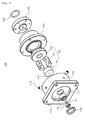
FIG.3 is an exploded view showing the beam dump according to the present invention. -
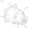
FIG.4 is a perspective view showing the outer appearance of the beam dump in the assembling state. -
FIG.5a is a sectional view showing a state where the beam dump is mounted on the rear side of an optical chamber. -
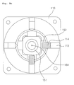
FIG.5b is a sectional view taken along the line A-A ofFIG.5a . -
FIG.6 is a schematic view showing an operating principle of the beam dump according to the present invention. - Hereinafter, an explanation on a beam dump for a particle counter or a fluorescence detector according to the present invention will be in detail given with reference to the attached drawings. Of course, the beam dump of the present invention is applicable to the fluorescence detector, and in this case, since the fluorescence detector and the particle counter are just divided in accordance with the existence of a fluorescence signal-measuring part, a detailed explanation on the fluorescence detector will be avoided for the brevity of the description.
- Referring first to
FIGS.2a and2b , a configuration of a particle counter on which a beam dump according to the present invention is mounted will be discussed. - As shown in
FIGS.2a and2b , the particle counter on which thebeam dump 100 according to the present invention is mounted includes anoptical chamber 220, a particle-introducingpart 210 and a particle-ejecting part (not shown) disposed on the upper and lower sides of theoptical chamber 220, a beam-formingpart 230 and thebeam dump 100 disposed on the front and rear sides of theoptical chamber 220, and a light-measuringpart 240 disposed on any one (the left side in the drawings) of left and right sides of theoptical chamber 220. - According to the particle counter under the above-mentioned configuration, fine particles in the air are introduced into the
optical chamber 220 through the particle-introducingpart 210, together with a given airflow, and at this time, the fine particles are passed through a laser beam irradiated from the beam-formingpart 230 to thebeam dump 100, thereby generating scattering light in theoptical chamber 220. Next, the scattering light is detected through the light-measuringpart 240, thereby measuring the concentration of the fine particles in the air. If the fine particles are bioparticles, fluorescent light occurs together with the scattering light. When the fluorescent light is detected, the concentration of the bioparticles in the air can be measured. - Further, as shown in
FIGS.3 to 6 , thebeam dump 100 according to the present invention includes: abody 110 adapted to be fixed to the rear surface of theoptical chamber 220 by means of screws; afocal lens assembly 120 adapted to be fitted to aninsertion hole 111 penetrating into the center portion of thebody 110; amounting groove 112 formed concavedly on the front surface of thebody 110 in such a manner as to position theinsertion hole 111 on the center thereof; awindow 140 adapted to be insertedly fixed to themounting groove 112; afixing ring 130 adapted to be fitted to the outer periphery of thefocal lens assembly 120 in such a manner as to be covered with thewindow 140; apin hole assembly 150 adapted to be fitted to a concave portion formed on the rear surface of thebody 110 in such a manner as to be positioned on the center of theinsertion hole 111; ahousing 160 adapted to be fixed to the rear end of thebody 110 by means of screws; a lightsource output detector 180 adapted to be fixed to the rear end of thehousing 160 by means of screws; asealing ring 190 adapted to be fitted to a ring groove formed on the center portion of the rear surface of the lightsource output detector 180; and acover plate 170 adapted to be fixed to the rear surface of the lightsource output detector 180. - As shown in
FIG.5a , theoptical chamber 220 may have light-measuring parts - The
focal lens assembly 120 makes use of aconvex lens 121 as a focal lens so as to permit a laser beam to be passed through a pin hole 154 (for example, having a diameter of 0.3mm) of thepin hole assembly 150. - The
pin hole assembly 150 includes: acylindrical cap 151 having thepin hole 154 penetrating into the center of the front surface thereof; a plurality of blocks 152 (for example, four blocks) adapted to be fitted between the outer periphery of thecap 151 and the inner periphery of the concave portion formed on the rear surface of thebody 110; and anend member 153 adapted to be brought into contact with the rear surface of thecap 151. - The
pin hole 154 penetrates in such a manner as to be decreased gradually in diameter toward the front surface of thecap 151. - The
end member 153 has a hole penetrating into the center thereof in such a manner as to be larger in diameter on the rear surface thereof than on the front surface thereof, and in this case, the diameter of the hole on the front surface thereof is the same as the inner diameter of the concave portion formed on the rear surface of thecap 151. - Next, the
body 110 has a plurality of equally spaced position adjusting members 113 (for example, four position adjusting members) coupled penetratingly to the outer periphery thereof. Theposition adjusting members 113 haverespective springs 114 mounted to press theblocks 152 toward the outer periphery of thecap 151, and thus, as they are fastened or unfastened, the position of thecap 151 can be adjusted within the concave portion formed on the rear surface of thebody 110. - Further, the
housing 160 has a hole penetrating into the center thereof in such a manner as to be larger in diameter on the front surface thereof than on the rear surface thereof, and in this case, the diameter of the hole on the front surface of thehousing 160 is the same as the diameter of the hole on the rear surface formed penetratingly into the center of theend member 153. - Moreover, the rear surface of the
housing 160 is inclined by a given angle θ (for example, 10°) with respect to the reference plane perpendicular to a light axis. - The light
source output detector 180 is adapted to detect the variations in the intensity of the laser beam if the beam-formingpart 230 and thebeam dump 100 are not aligned to each other on the front and rear sides of theoptical chamber 220 or if the beam-formingpart 230 has a malfunction, and then, to generate an alarming signal through an alarming device (not shown). A photodiode is used as the lightsource output detector 180. - Next, an explanation on the operating effect of the
beam dump 100 according to the present invention will be given. - According to the present invention, first, the
beam dump 100 is made to an integrated body in such a manner as to forcedly fit some of parts and to fix some of parts by means of screws, and therefore, it is easy to perform the assembling and disassembling of the parts and it is convenient to be mounted on the particle counter. - Further, the space opened between the front surface of the
body 110 and the rear surface of theoptical chamber 220 is closed by means of thewindow 140 and thefixing ring 130, such that the internal pressure of theoptical chamber 220 is maintained and the internal passage (or the internal space) of thebeam dump 100 through which the laser beam is passed is shielded from the outside, thereby preventing outside air or light from being introduced into theoptical chamber 220 or thebeam dump 100. Therefore, the accuracy and reliability of the measurement can be improved. - According to the present invention, moreover, the
beam dump 100 is configured wherein the laser beam (incident beam) irradiated from the beam-formingpart 230 is passed through the openings formed on the front and rear surfaces of theoptical chamber 220, thewindow 140, and theconvex lens 121 of thefocal lens assembly 120 and is then passed through thepin hole 154 having a diameter of 0.3mm penetrating into the front surface of thecap 151 of thepin hole assembly 150, thereby finally reaching the lightsource output detector 180. Furthermore, the surface of the lightsource output detector 180 is inclined by 10° with respect to the reference plane perpendicular to the advancing passage (light axis) of the incident light. Under the above configuration, even though a portion of the incident beam is reflected from the surface of the lightsource output detector 180 during the measurement of the intensity of the laser beam, the reflected beam has a different passage from the incident beam, such that an amount of reflected beam directly advancing toward thepin hole 154 can be remarkably reduced. - In more detail, as shown in
FIG.6 , the incident beam is collected to thepin hole 154 of thepin hole assembly 150 through theconvex lens 121 of thefocal lens assembly 120, and after passing through thepin hole 154, the incident beam becomes gradually near the lightsource output detector 180, while being passed through acavity 101 formed inside thebeam dump 100 from the rear side of thepin hole 154, thereby permitting the width of the beam to be spread. - Like this, if the incident beam spread in width reaches the light
source output detector 180, the intensity of the incident beam is detected by means of the lightsource output detector 180, and a portion of the incident beam is reflected on the surface of the lightsource output detector 180. - As the reflected beam on the surface of the light
source output detector 180 becomes gradually near thepin hole assembly 150, the width of the beam is more spread by 20 times than the diameter of thepin hole 154. - If it is assumed that a silicon photodiode is used as the light
source output detector 180, when the incident beam is introduced perpendicularly (90°) into the surface of the photodiode, the reflection rate is just 30%, but it is introduced slantly by a given angle (90°-10°=80°) thereinto, the reflection rate is just 0.075%. When the Gaussian distribution of the beam is considered, the energy of the beam is just 0.2%. - According to the present invention, most of the beam reflected from the surface of the light
source output detector 180 is not passed through thepin hole 154. Even though the reflected beam is passed through thepin hole 154, further, it is just passed through an area in which the outside intensity is low in the Gaussian distribution of the beam, such that only an extremely small amount of energy is introduced into theoptical chamber 220. - As described above, according to the
beam dump 100 of the present invention, the reflected light from the surface of the lightsource output detector 180 and the stray light generated inside thebeam dump 100 are rarely introduced into theoptical chamber 220, thereby improving the signal to noise ratio (the energy ratio between signal and noise) of another detector (for example, the light-measuring parts 240 and 250) mounted on theoptical chamber 220 and enhancing the accuracy and reliability of the measurement of the particle counter or the fluorescence detector. - While the present invention has been described with reference to the particular illustrative embodiments, it is not to be restricted by the embodiments but only by the appended claims. It is to be appreciated that those skilled in the art can change or modify the embodiments without departing from the scope of the claims.
Claims (3)
- A beam dump (100) for a particle counter or a fluorescence detector that is mounted on one side of an optical chamber (220) in such a manner as to be opposite to a beam-forming part (230) mounted on the other side of the optical chamber (220), so as to dump the beam irradiated from the beam-forming part (230), the beam dump (100) comprising:a body (110) adapted to be fixed to the optical chamber (220);a focal lens assembly (120) adapted to be fitted to an insertion hole (111) penetrating into the center of the body (110);a pin hole assembly (150) adapted to be inserted into a concave portion formed on the rear surface of the body (110) in such a manner as to pass a light axis of the focal lens assembly (120) through a pin hole (154);a housing adapted to be fixed to the rear surface of the pin hole assembly (150); anda light source output detector (180) adapted to be fixed to the rear surface of the housing (160) in such a manner as to be inclined to a given angle (θ) with respect to a reference plane perpendicular to the light axis of the focal lens assembly (120),wherein the pin hole assembly (150) and the housing (160) have a cavity formed in the center portions thereof, such that as the beam passed through the pin hole (154) of the pin hole assembly (150) becomes gradually near the light source output detector, the width of the beam becomes spread.
- The beam dump according to claim 1, wherein the pin hole assembly (150) comprises a cap (151) having the pin hole (154) penetrating into the center of the front surface thereof, a plurality of blocks (152) adapted to be fitted between the outer periphery of the cap (151) and the inner periphery of the concave portion formed on the rear surface of the body, and an end member adapted to be brought into contact with the rear surface of the cap (151), and the body has a plurality of equally spaced position adjusting members coupled penetratingly to the outer periphery thereof so as to adjust the position of the cap within the concave portion formed on the rear surface thereof.
- The beam dump according to claim 2, wherein the pin hole (154) on the cap of the pin hole assembly (150) penetrates in such a manner as to be increased gradually in diameter along the advancing passage of the incident beam therethrough, a hole on the end member of the pin hole assembly penetrates in such a manner as to be increased gradually in diameter along the advancing passage of the incident beam through the pin hole (154), and a hole on the housing penetrates in such a manner as to be decreased gradually in diameter along the advancing passage of the incident beam through the pin hole (154).
Applications Claiming Priority (1)
| Application Number | Priority Date | Filing Date | Title |
|---|---|---|---|
| KR1020110132029A KR101139776B1 (en) | 2011-12-09 | 2011-12-09 | A beam dumper for a particle counter or a fluorescence detector |
Publications (2)
| Publication Number | Publication Date |
|---|---|
| EP2602645A1 EP2602645A1 (en) | 2013-06-12 |
| EP2602645B1 true EP2602645B1 (en) | 2014-03-26 |
Family
ID=45976763
Family Applications (1)
| Application Number | Title | Priority Date | Filing Date |
|---|---|---|---|
| EP12163568.4A Active EP2602645B1 (en) | 2011-12-09 | 2012-04-10 | Beam dump for particle counter or fluorescence detector |
Country Status (2)
| Country | Link |
|---|---|
| EP (1) | EP2602645B1 (en) |
| KR (1) | KR101139776B1 (en) |
Families Citing this family (4)
| Publication number | Priority date | Publication date | Assignee | Title |
|---|---|---|---|---|
| DE102012219635A1 (en) * | 2012-10-26 | 2014-02-13 | Trumpf Laser Gmbh + Co. Kg | Device for absorbing a laser beam |
| KR101580932B1 (en) | 2015-08-28 | 2015-12-31 | 국방과학연구소 | Beam dumper for measuring beam output and monitoring optical alignment and stray light attenuation of particle counter |
| CN108020859B (en) * | 2017-12-29 | 2023-12-29 | 合肥中科离子医学技术装备有限公司 | Adjustable transmission device for measuring transverse parameters of beam |
| KR102055426B1 (en) | 2018-10-15 | 2019-12-12 | 국방과학연구소 | Beam Dumper for High Power Fiber Laser and Method for Assembling the same |
Family Cites Families (10)
| Publication number | Priority date | Publication date | Assignee | Title |
|---|---|---|---|---|
| US20020028434A1 (en) | 2000-09-06 | 2002-03-07 | Guava Technologies, Inc. | Particle or cell analyzer and method |
| US7071444B2 (en) * | 2003-11-24 | 2006-07-04 | The Boeing Company | High performance system and method for capturing and absorbing radiation |
| KR200367121Y1 (en) | 2004-07-28 | 2004-11-10 | 주식회사 라이다텍 | Optical particle counter for sub-micron particles |
| KR100772488B1 (en) * | 2006-02-28 | 2007-11-05 | (주)에이치시티 | Particle measuring device and method |
| US20080089382A1 (en) * | 2006-10-16 | 2008-04-17 | Eigler Lynne C | Planar beam dump |
| JP5194464B2 (en) * | 2007-01-31 | 2013-05-08 | 株式会社島津製作所 | Spectrometer |
| US8047663B2 (en) * | 2007-09-24 | 2011-11-01 | Coherent, Inc. | Beam dump for a very-high-intensity laser beam |
| KR101692452B1 (en) * | 2008-09-05 | 2017-01-03 | 엑스트랄리스 테크놀로지 리미티드 | Optical detection of particle characteristics |
| JP2010236920A (en) * | 2009-03-30 | 2010-10-21 | Jasco Corp | Fine particle measuring device |
| US8342690B2 (en) * | 2010-04-29 | 2013-01-01 | Eastman Kodak Company | Off-state light baffle for digital projection |
-
2011
- 2011-12-09 KR KR1020110132029A patent/KR101139776B1/en active Active
-
2012
- 2012-04-10 EP EP12163568.4A patent/EP2602645B1/en active Active
Also Published As
| Publication number | Publication date |
|---|---|
| EP2602645A1 (en) | 2013-06-12 |
| KR101139776B1 (en) | 2012-04-26 |
Similar Documents
| Publication | Publication Date | Title |
|---|---|---|
| US7088447B1 (en) | Particle counter with self-concealing aperture assembly | |
| US20040080747A1 (en) | Low noise intracavity laser particle counter | |
| EP2602645A1 (en) | Beam dump for particle counter or fluorescence detector | |
| JP2009276361A (en) | Particle counter equipped with strapped laser diode | |
| EP2472248A2 (en) | Microparticle detection apparatus | |
| JP2016224034A (en) | Grain particle sensor device | |
| US20110255086A1 (en) | Optical sample detection system and sample analysis device | |
| US10088363B2 (en) | Biometric sensor and biometric analysis system including the same | |
| US20210025837A1 (en) | Kikuchi diffraction detector | |
| US7248363B2 (en) | Particle size analyzer | |
| CN105593662B (en) | Device and method for the size for determining the particle in fluid | |
| CN109901288B (en) | A direct laser light and its forward scattered light optical trap device | |
| KR100959611B1 (en) | Non-dispersive Infrared Gas Analyzer with Intensive Lens | |
| US20140111802A1 (en) | Low stray light polychromator | |
| JP2004219131A (en) | Oil mist detector | |
| KR102400468B1 (en) | Optical system for counting particles | |
| US9360424B2 (en) | Device for calibrating a scatterometer | |
| JP2004198416A (en) | Equipment for measuring the thickness of thin layers | |
| CN114674731B (en) | A particle counting sensor | |
| CN211927089U (en) | Time division multiplexing double-beam photometric device | |
| KR101580932B1 (en) | Beam dumper for measuring beam output and monitoring optical alignment and stray light attenuation of particle counter | |
| US10935480B1 (en) | Optical-particle sensor head | |
| JP6988714B2 (en) | Particle counting device | |
| CN221550416U (en) | Particle counting sensor | |
| CN113533144B (en) | Laser particle size analysis device |
Legal Events
| Date | Code | Title | Description |
|---|---|---|---|
| PUAI | Public reference made under article 153(3) epc to a published international application that has entered the european phase |
Free format text: ORIGINAL CODE: 0009012 |
|
| 17P | Request for examination filed |
Effective date: 20120410 |
|
| AK | Designated contracting states |
Kind code of ref document: A1 Designated state(s): AL AT BE BG CH CY CZ DE DK EE ES FI FR GB GR HR HU IE IS IT LI LT LU LV MC MK MT NL NO PL PT RO RS SE SI SK SM TR |
|
| AX | Request for extension of the european patent |
Extension state: BA ME |
|
| GRAP | Despatch of communication of intention to grant a patent |
Free format text: ORIGINAL CODE: EPIDOSNIGR1 |
|
| RBV | Designated contracting states (corrected) |
Designated state(s): AL AT BE BG CH CY CZ DE DK EE ES FI FR GB GR HR HU IE IS IT LI LT LU LV MC MK MT NL NO PL PT RO RS SE SI SK SM TR |
|
| RIC1 | Information provided on ipc code assigned before grant |
Ipc: G02B 5/00 20060101AFI20130709BHEP |
|
| INTG | Intention to grant announced |
Effective date: 20130731 |
|
| GRAS | Grant fee paid |
Free format text: ORIGINAL CODE: EPIDOSNIGR3 |
|
| GRAA | (expected) grant |
Free format text: ORIGINAL CODE: 0009210 |
|
| AK | Designated contracting states |
Kind code of ref document: B1 Designated state(s): AL AT BE BG CH CY CZ DE DK EE ES FI FR GB GR HR HU IE IS IT LI LT LU LV MC MK MT NL NO PL PT RO RS SE SI SK SM TR |
|
| REG | Reference to a national code |
Ref country code: GB Ref legal event code: FG4D |
|
| REG | Reference to a national code |
Ref country code: CH Ref legal event code: EP |
|
| REG | Reference to a national code |
Ref country code: AT Ref legal event code: REF Ref document number: 659265 Country of ref document: AT Kind code of ref document: T Effective date: 20140415 |
|
| REG | Reference to a national code |
Ref country code: IE Ref legal event code: FG4D |
|
| REG | Reference to a national code |
Ref country code: DE Ref legal event code: R096 Ref document number: 602012001183 Country of ref document: DE Effective date: 20140508 |
|
| PG25 | Lapsed in a contracting state [announced via postgrant information from national office to epo] |
Ref country code: NO Free format text: LAPSE BECAUSE OF FAILURE TO SUBMIT A TRANSLATION OF THE DESCRIPTION OR TO PAY THE FEE WITHIN THE PRESCRIBED TIME-LIMIT Effective date: 20140626 Ref country code: LT Free format text: LAPSE BECAUSE OF FAILURE TO SUBMIT A TRANSLATION OF THE DESCRIPTION OR TO PAY THE FEE WITHIN THE PRESCRIBED TIME-LIMIT Effective date: 20140326 |
|
| REG | Reference to a national code |
Ref country code: AT Ref legal event code: MK05 Ref document number: 659265 Country of ref document: AT Kind code of ref document: T Effective date: 20140326 |
|
| REG | Reference to a national code |
Ref country code: NL Ref legal event code: VDEP Effective date: 20140326 |
|
| REG | Reference to a national code |
Ref country code: LT Ref legal event code: MG4D |
|
| PG25 | Lapsed in a contracting state [announced via postgrant information from national office to epo] |
Ref country code: SE Free format text: LAPSE BECAUSE OF FAILURE TO SUBMIT A TRANSLATION OF THE DESCRIPTION OR TO PAY THE FEE WITHIN THE PRESCRIBED TIME-LIMIT Effective date: 20140326 Ref country code: FI Free format text: LAPSE BECAUSE OF FAILURE TO SUBMIT A TRANSLATION OF THE DESCRIPTION OR TO PAY THE FEE WITHIN THE PRESCRIBED TIME-LIMIT Effective date: 20140326 |
|
| PG25 | Lapsed in a contracting state [announced via postgrant information from national office to epo] |
Ref country code: LV Free format text: LAPSE BECAUSE OF FAILURE TO SUBMIT A TRANSLATION OF THE DESCRIPTION OR TO PAY THE FEE WITHIN THE PRESCRIBED TIME-LIMIT Effective date: 20140326 Ref country code: RS Free format text: LAPSE BECAUSE OF FAILURE TO SUBMIT A TRANSLATION OF THE DESCRIPTION OR TO PAY THE FEE WITHIN THE PRESCRIBED TIME-LIMIT Effective date: 20140326 Ref country code: HR Free format text: LAPSE BECAUSE OF FAILURE TO SUBMIT A TRANSLATION OF THE DESCRIPTION OR TO PAY THE FEE WITHIN THE PRESCRIBED TIME-LIMIT Effective date: 20140326 |
|
| PG25 | Lapsed in a contracting state [announced via postgrant information from national office to epo] |
Ref country code: NL Free format text: LAPSE BECAUSE OF FAILURE TO SUBMIT A TRANSLATION OF THE DESCRIPTION OR TO PAY THE FEE WITHIN THE PRESCRIBED TIME-LIMIT Effective date: 20140326 Ref country code: EE Free format text: LAPSE BECAUSE OF FAILURE TO SUBMIT A TRANSLATION OF THE DESCRIPTION OR TO PAY THE FEE WITHIN THE PRESCRIBED TIME-LIMIT Effective date: 20140326 Ref country code: BG Free format text: LAPSE BECAUSE OF FAILURE TO SUBMIT A TRANSLATION OF THE DESCRIPTION OR TO PAY THE FEE WITHIN THE PRESCRIBED TIME-LIMIT Effective date: 20140626 Ref country code: CY Free format text: LAPSE BECAUSE OF FAILURE TO SUBMIT A TRANSLATION OF THE DESCRIPTION OR TO PAY THE FEE WITHIN THE PRESCRIBED TIME-LIMIT Effective date: 20140326 Ref country code: CZ Free format text: LAPSE BECAUSE OF FAILURE TO SUBMIT A TRANSLATION OF THE DESCRIPTION OR TO PAY THE FEE WITHIN THE PRESCRIBED TIME-LIMIT Effective date: 20140326 Ref country code: BE Free format text: LAPSE BECAUSE OF FAILURE TO SUBMIT A TRANSLATION OF THE DESCRIPTION OR TO PAY THE FEE WITHIN THE PRESCRIBED TIME-LIMIT Effective date: 20140326 Ref country code: IS Free format text: LAPSE BECAUSE OF FAILURE TO SUBMIT A TRANSLATION OF THE DESCRIPTION OR TO PAY THE FEE WITHIN THE PRESCRIBED TIME-LIMIT Effective date: 20140726 Ref country code: RO Free format text: LAPSE BECAUSE OF FAILURE TO SUBMIT A TRANSLATION OF THE DESCRIPTION OR TO PAY THE FEE WITHIN THE PRESCRIBED TIME-LIMIT Effective date: 20140326 |
|
| PG25 | Lapsed in a contracting state [announced via postgrant information from national office to epo] |
Ref country code: AT Free format text: LAPSE BECAUSE OF FAILURE TO SUBMIT A TRANSLATION OF THE DESCRIPTION OR TO PAY THE FEE WITHIN THE PRESCRIBED TIME-LIMIT Effective date: 20140326 Ref country code: MC Free format text: LAPSE BECAUSE OF FAILURE TO SUBMIT A TRANSLATION OF THE DESCRIPTION OR TO PAY THE FEE WITHIN THE PRESCRIBED TIME-LIMIT Effective date: 20140326 Ref country code: ES Free format text: LAPSE BECAUSE OF FAILURE TO SUBMIT A TRANSLATION OF THE DESCRIPTION OR TO PAY THE FEE WITHIN THE PRESCRIBED TIME-LIMIT Effective date: 20140326 Ref country code: PL Free format text: LAPSE BECAUSE OF FAILURE TO SUBMIT A TRANSLATION OF THE DESCRIPTION OR TO PAY THE FEE WITHIN THE PRESCRIBED TIME-LIMIT Effective date: 20140326 Ref country code: SK Free format text: LAPSE BECAUSE OF FAILURE TO SUBMIT A TRANSLATION OF THE DESCRIPTION OR TO PAY THE FEE WITHIN THE PRESCRIBED TIME-LIMIT Effective date: 20140326 |
|
| PG25 | Lapsed in a contracting state [announced via postgrant information from national office to epo] |
Ref country code: PT Free format text: LAPSE BECAUSE OF FAILURE TO SUBMIT A TRANSLATION OF THE DESCRIPTION OR TO PAY THE FEE WITHIN THE PRESCRIBED TIME-LIMIT Effective date: 20140728 |
|
| REG | Reference to a national code |
Ref country code: DE Ref legal event code: R097 Ref document number: 602012001183 Country of ref document: DE |
|
| REG | Reference to a national code |
Ref country code: IE Ref legal event code: MM4A |
|
| PG25 | Lapsed in a contracting state [announced via postgrant information from national office to epo] |
Ref country code: DK Free format text: LAPSE BECAUSE OF FAILURE TO SUBMIT A TRANSLATION OF THE DESCRIPTION OR TO PAY THE FEE WITHIN THE PRESCRIBED TIME-LIMIT Effective date: 20140326 |
|
| PLBE | No opposition filed within time limit |
Free format text: ORIGINAL CODE: 0009261 |
|
| STAA | Information on the status of an ep patent application or granted ep patent |
Free format text: STATUS: NO OPPOSITION FILED WITHIN TIME LIMIT |
|
| 26N | No opposition filed |
Effective date: 20150106 |
|
| PG25 | Lapsed in a contracting state [announced via postgrant information from national office to epo] |
Ref country code: IT Free format text: LAPSE BECAUSE OF FAILURE TO SUBMIT A TRANSLATION OF THE DESCRIPTION OR TO PAY THE FEE WITHIN THE PRESCRIBED TIME-LIMIT Effective date: 20140326 |
|
| REG | Reference to a national code |
Ref country code: DE Ref legal event code: R097 Ref document number: 602012001183 Country of ref document: DE Effective date: 20150106 |
|
| PG25 | Lapsed in a contracting state [announced via postgrant information from national office to epo] |
Ref country code: IE Free format text: LAPSE BECAUSE OF NON-PAYMENT OF DUE FEES Effective date: 20140410 |
|
| PG25 | Lapsed in a contracting state [announced via postgrant information from national office to epo] |
Ref country code: SI Free format text: LAPSE BECAUSE OF FAILURE TO SUBMIT A TRANSLATION OF THE DESCRIPTION OR TO PAY THE FEE WITHIN THE PRESCRIBED TIME-LIMIT Effective date: 20140326 |
|
| REG | Reference to a national code |
Ref country code: CH Ref legal event code: PL |
|
| PG25 | Lapsed in a contracting state [announced via postgrant information from national office to epo] |
Ref country code: CH Free format text: LAPSE BECAUSE OF NON-PAYMENT OF DUE FEES Effective date: 20150430 Ref country code: LI Free format text: LAPSE BECAUSE OF NON-PAYMENT OF DUE FEES Effective date: 20150430 |
|
| PG25 | Lapsed in a contracting state [announced via postgrant information from national office to epo] |
Ref country code: MT Free format text: LAPSE BECAUSE OF FAILURE TO SUBMIT A TRANSLATION OF THE DESCRIPTION OR TO PAY THE FEE WITHIN THE PRESCRIBED TIME-LIMIT Effective date: 20140326 |
|
| PG25 | Lapsed in a contracting state [announced via postgrant information from national office to epo] |
Ref country code: SM Free format text: LAPSE BECAUSE OF FAILURE TO SUBMIT A TRANSLATION OF THE DESCRIPTION OR TO PAY THE FEE WITHIN THE PRESCRIBED TIME-LIMIT Effective date: 20140326 |
|
| PG25 | Lapsed in a contracting state [announced via postgrant information from national office to epo] |
Ref country code: GR Free format text: LAPSE BECAUSE OF FAILURE TO SUBMIT A TRANSLATION OF THE DESCRIPTION OR TO PAY THE FEE WITHIN THE PRESCRIBED TIME-LIMIT Effective date: 20140627 |
|
| PG25 | Lapsed in a contracting state [announced via postgrant information from national office to epo] |
Ref country code: LU Free format text: LAPSE BECAUSE OF NON-PAYMENT OF DUE FEES Effective date: 20140410 Ref country code: TR Free format text: LAPSE BECAUSE OF FAILURE TO SUBMIT A TRANSLATION OF THE DESCRIPTION OR TO PAY THE FEE WITHIN THE PRESCRIBED TIME-LIMIT Effective date: 20140326 Ref country code: HU Free format text: LAPSE BECAUSE OF FAILURE TO SUBMIT A TRANSLATION OF THE DESCRIPTION OR TO PAY THE FEE WITHIN THE PRESCRIBED TIME-LIMIT; INVALID AB INITIO Effective date: 20120410 |
|
| REG | Reference to a national code |
Ref country code: FR Ref legal event code: PLFP Year of fee payment: 6 |
|
| REG | Reference to a national code |
Ref country code: FR Ref legal event code: PLFP Year of fee payment: 7 |
|
| PG25 | Lapsed in a contracting state [announced via postgrant information from national office to epo] |
Ref country code: MK Free format text: LAPSE BECAUSE OF FAILURE TO SUBMIT A TRANSLATION OF THE DESCRIPTION OR TO PAY THE FEE WITHIN THE PRESCRIBED TIME-LIMIT Effective date: 20140326 |
|
| PG25 | Lapsed in a contracting state [announced via postgrant information from national office to epo] |
Ref country code: AL Free format text: LAPSE BECAUSE OF FAILURE TO SUBMIT A TRANSLATION OF THE DESCRIPTION OR TO PAY THE FEE WITHIN THE PRESCRIBED TIME-LIMIT Effective date: 20140326 |
|
| PGFP | Annual fee paid to national office [announced via postgrant information from national office to epo] |
Ref country code: DE Payment date: 20250429 Year of fee payment: 14 |
|
| PGFP | Annual fee paid to national office [announced via postgrant information from national office to epo] |
Ref country code: FR Payment date: 20250430 Year of fee payment: 14 |
|
| PGFP | Annual fee paid to national office [announced via postgrant information from national office to epo] |
Ref country code: GB Payment date: 20260327 Year of fee payment: 15 |