EP2602548A1 - Leaf spring damper for a turbine engine fuel delivery system - Google Patents
Leaf spring damper for a turbine engine fuel delivery system Download PDFInfo
- Publication number
- EP2602548A1 EP2602548A1 EP20120187510 EP12187510A EP2602548A1 EP 2602548 A1 EP2602548 A1 EP 2602548A1 EP 20120187510 EP20120187510 EP 20120187510 EP 12187510 A EP12187510 A EP 12187510A EP 2602548 A1 EP2602548 A1 EP 2602548A1
- Authority
- EP
- European Patent Office
- Prior art keywords
- spray bar
- segment
- leaf spring
- bar contact
- contact segment
- Prior art date
- Legal status (The legal status is an assumption and is not a legal conclusion. Google has not performed a legal analysis and makes no representation as to the accuracy of the status listed.)
- Withdrawn
Links
- 239000000446 fuel Substances 0.000 title claims abstract description 8
- 239000007921 spray Substances 0.000 claims abstract description 97
- 230000007704 transition Effects 0.000 claims description 24
- 230000000712 assembly Effects 0.000 description 4
- 238000000429 assembly Methods 0.000 description 4
- 230000036316 preload Effects 0.000 description 3
- 150000001875 compounds Chemical class 0.000 description 1
- 238000013016 damping Methods 0.000 description 1
Images


Classifications
-
- F—MECHANICAL ENGINEERING; LIGHTING; HEATING; WEAPONS; BLASTING
- F02—COMBUSTION ENGINES; HOT-GAS OR COMBUSTION-PRODUCT ENGINE PLANTS
- F02K—JET-PROPULSION PLANTS
- F02K3/00—Plants including a gas turbine driving a compressor or a ducted fan
- F02K3/08—Plants including a gas turbine driving a compressor or a ducted fan with supplementary heating of the working fluid; Control thereof
- F02K3/10—Plants including a gas turbine driving a compressor or a ducted fan with supplementary heating of the working fluid; Control thereof by after-burners
-
- F—MECHANICAL ENGINEERING; LIGHTING; HEATING; WEAPONS; BLASTING
- F02—COMBUSTION ENGINES; HOT-GAS OR COMBUSTION-PRODUCT ENGINE PLANTS
- F02C—GAS-TURBINE PLANTS; AIR INTAKES FOR JET-PROPULSION PLANTS; CONTROLLING FUEL SUPPLY IN AIR-BREATHING JET-PROPULSION PLANTS
- F02C7/00—Features, components parts, details or accessories, not provided for in, or of interest apart form groups F02C1/00 - F02C6/00; Air intakes for jet-propulsion plants
- F02C7/22—Fuel supply systems
- F02C7/222—Fuel flow conduits, e.g. manifolds
-
- F—MECHANICAL ENGINEERING; LIGHTING; HEATING; WEAPONS; BLASTING
- F23—COMBUSTION APPARATUS; COMBUSTION PROCESSES
- F23R—GENERATING COMBUSTION PRODUCTS OF HIGH PRESSURE OR HIGH VELOCITY, e.g. GAS-TURBINE COMBUSTION CHAMBERS
- F23R3/00—Continuous combustion chambers using liquid or gaseous fuel
- F23R3/02—Continuous combustion chambers using liquid or gaseous fuel characterised by the air-flow or gas-flow configuration
- F23R3/16—Continuous combustion chambers using liquid or gaseous fuel characterised by the air-flow or gas-flow configuration with devices inside the flame tube or the combustion chamber to influence the air or gas flow
- F23R3/18—Flame stabilising means, e.g. flame holders for after-burners of jet-propulsion plants
- F23R3/20—Flame stabilising means, e.g. flame holders for after-burners of jet-propulsion plants incorporating fuel injection means
-
- F—MECHANICAL ENGINEERING; LIGHTING; HEATING; WEAPONS; BLASTING
- F23—COMBUSTION APPARATUS; COMBUSTION PROCESSES
- F23R—GENERATING COMBUSTION PRODUCTS OF HIGH PRESSURE OR HIGH VELOCITY, e.g. GAS-TURBINE COMBUSTION CHAMBERS
- F23R3/00—Continuous combustion chambers using liquid or gaseous fuel
- F23R3/28—Continuous combustion chambers using liquid or gaseous fuel characterised by the fuel supply
- F23R3/283—Attaching or cooling of fuel injecting means including supports for fuel injectors, stems, or lances
-
- F—MECHANICAL ENGINEERING; LIGHTING; HEATING; WEAPONS; BLASTING
- F05—INDEXING SCHEMES RELATING TO ENGINES OR PUMPS IN VARIOUS SUBCLASSES OF CLASSES F01-F04
- F05D—INDEXING SCHEME FOR ASPECTS RELATING TO NON-POSITIVE-DISPLACEMENT MACHINES OR ENGINES, GAS-TURBINES OR JET-PROPULSION PLANTS
- F05D2260/00—Function
- F05D2260/96—Preventing, counteracting or reducing vibration or noise
Definitions
- the present invention relates generally to turbine engines and, in particular, to a turbine engine fuel delivery system that includes a leaf spring damper.
- a gas turbine engine may include a central gas path that extends sequentially through a fan, a compressor, a combustor, a turbine, and an augmentor between a forward engine airflow inlet and an aft engine airflow exhaust.
- the augmentor may include a plurality of spray bar assemblies arranged within the central gas path. Each spray bar assembly typically extends from a first assembly end to a second assembly end, which may be connected to an end of a respective trailing edge box. Such spray bar assemblies are typically subject to engine vibrations that may reduce fuel delivery performance of the spray bar assemblies.
- a fuel delivery system for gas turbine engine includes a mounting platform, a spray bar assembly and a leaf spring damper with a stack of a plurality of leaf springs.
- the stack includes a base segment connected longitudinally between a first spray bar contact segment and a second spray bar contact segment.
- the base segment is connected to the mounting platform and is located a first distance from the spray bar assembly.
- the first spray bar contact segment engages the spray bar assembly and is located a second distance from the mounting platform.
- the second spray bar contact segment engages the spray bar assembly and is located a third distance from the mounting platform.
- a gas turbine engine augmentor includes a flame holder with a mounting platform, a spray bar assembly and a leaf spring damper with a stack of a plurality of leaf springs.
- the stack includes a base segment connected longitudinally between a first spray bar contact segment and a second spray bar contact segment.
- the base segment is connected to the mounting platform and is arranged in spaced relationship to the spray bar assembly.
- the first spray bar contact segment engages the spray bar assembly and is arranged in spaced relationship to the mounting platform.
- the second spray bar contact segment engages the spray bar assembly and is arranged in spaced relationship to the mounting platform.
- FIG. 1 illustrates a portion of a gas turbine engine augmentor 10.
- the augmentor 10 includes a trailing edge box 12, a spray bar assembly 14 and a flame holder assembly 16.
- the trailing edge box 12 includes an inner box cavity 18 that extends radially between a radial inner endwall 20 and a radial outer endwall 22.
- the inner box cavity 18 extends laterally (e.g., circumferentially) between a first box sidewall 24 and a second box sidewall 26.
- the inner box cavity 18 also extends axially from a turbine exhaust case strut 28 to a trailing edge box aperture 30.
- the spray bar assembly 14 extends longitudinally (e.g., radially and axially) between a first spray bar end 32 and a second spray bar end 34.
- the spray bar assembly 14 may include one or more fuel conduits 36 and 38, each having one or more spray bar nozzle assemblies 40.
- Each spray bar nozzle assembly 40 may include a nozzle 42 that extends laterally from a respective one of the fuel conduits 36, 38 through an injector wear block 44.
- each injector wear block 44 may include a wear block flat, e.g., 46 or 48.
- An example of an alternative spray bar assembly configuration is disclosed in U.S. Patent Nos. 7,647,775 and 7,578,131 .
- the flame holder assembly 16 may include a mounting platform 50 (e.g., an impingement sheet assembly), one or more attachment lugs 52, and a leaf spring damper 54.
- the mounting platform 50 has a mounting surface 56 that extends longitudinally between a first platform endwall 58 (e.g., a radial inner endwall) and a second platform endwall 60 (e.g., a radial outer endwall).
- the mounting surface 56 also extends laterally between a first platform sidewall 62 and a second platform sidewall 64.
- An example of an attachment lug is disclosed in U.S. Patent Application Serial No. 12/112,470 .
- the leaf spring damper 54 includes a stack 66 of a plurality of leaf springs.
- the stack 66 illustrated in FIG. 2 includes a first leaf spring 68, a second leaf spring 70 and a third leaf spring 72.
- the stack 66 extends longitudinally between a first stack end 74 and a second stack end 76.
- the stack 66 may include a base segment 78, a first spray bar contact segment 80, a second spray bar contact segment 82, a first transition segment 84 and a second transition segment 86.
- the base segment 78 is connected longitudinally between the first spray bar contact segment 80 and the second spray bar contact segment 82, and extends longitudinally between the first transition segment 84 and the second transition segment 86.
- the first spray bar contact segment 80 extends longitudinally between the first transition segment 84 and the first stack end 74.
- the second spray bar contact segment 82 extends longitudinally between the second transition segment 86 and the second stack end 76.
- the first transition segment 84 and the second transition segment 86 may each have a (e.g., compound) curved and/or stepped sectional geometry.
- the base segment 78 has a lateral base segment width 88.
- the first spray bar contact segment 80 and the second spray bar contact segment 82 each have a respective lateral contact segment width 90, 92.
- the first transition segment 84 and the second transition segment 86 each have a respective lateral transition segment width 94, 96.
- the base segment width 88 may be greater than each of the transition segment widths 94 and 96.
- Each of the contact segment widths 90 and 92 may also be greater than each of the transition segment widths 94 and 96.
- the first leaf spring 68 may extend longitudinally between the first stack end 74 and the second stack end 76.
- the first leaf spring 68 may also extend laterally, in the base segment 78, between an anti-rotation first flange 98 and an anti-rotation second flange 100.
- the first flange 98 and the second flange 100 may each extend transversely (e.g., radially and axially) from the first leaf spring 68 to a respective distal end 102, 104 (see also FIG. 2 ).
- the second leaf spring 70 may extend longitudinally between the first spray bar contact segment 80 and the second spray bar contact segment 82 and, for example, partially into the first spray bar contact segment 80 and the second spray bar contact segment 82.
- the third leaf spring 72 may extend longitudinally between the first spray bar contact segment 80 and the second spray bar contact segment 82. Referring to FIG. 4 , the third leaf spring 72 may also extend laterally, in the base segment 78, between a first mounting flange 106 and a second mounting flange 108, which may collectively form a damper mounting bracket 110.
- the first mounting flange 106 and the second mounting flange 108 may each respectively include a first flange segment 112, 114 and a second flange segment 116, 118.
- Each first flange segment 112, 114 may respectively extend transversely from the third leaf spring 72 to the second flange segment 116, 118.
- Each second flange segment 116, 118 may respectively extend (e.g., laterally) from the first flange segment 112, 114 to a distal flange end 120, 122.
- the second leaf spring 70 may be stacked between the third leaf spring 72 and the first leaf spring 68.
- the second leaf spring 70 and the damper mounting bracket 110 may be seated (e.g., nested) between the first flange 98 and the second flange 100.
- At least one fastener 124 e.g., a single rivet
- the first flange 98 and the second flange 100 may reduce (or prevent) relative rotation between the damper mounting bracket 110 and the first leaf spring 68 and/or the second leaf spring 70 during engine operation.
- the second flange segments 116 and 118 are respectively connected to the mounting surface 56 with, for example, a plurality of fasteners 126 (e.g., rivets).
- a plurality of fasteners 126 e.g., rivets
- Each of the attachment lugs 52 may also be connected to the mounting surface 56 with, for example, a plurality of fasteners 128 (e.g., rivets).
- the spray bar assembly 14 is arranged within the inner box cavity 18, and the first spray bar end 32 may be connected to the radial inner endwall 20.
- the mounting platform 50 may be mated with the trailing edge box aperture 30, and connected to the trailing edge box 12 using the attachment lugs 52.
- the first spray bar contact segment 80 engages (e.g., contacts) and, for example, exerts a spring preload against the wear block flat 46.
- the second spray bar contact segment 82 engages and, for example, exerts a spring preload against the wear block flat 48.
- the spring preloads may be selected, for example, such that the contact segments 80 and 82 engage the spray bar assembly 14 throughout engine operation.
- the base segment 78 is located a non-zero first distance 129 from the spray bar assembly 14.
- the first spray bar contact segment 80 is located a non-zero second distance 130 from the mounting surface 56
- the second spray bar contact segment 82 is located a non-zero third distance 132 from the mounting surface 56.
- the first spray bar contact segment 80 and the second spray bar contact segment 82 therefore are in spaced relationship to and may move transversely relative to the base segment 78 and the mounting surface 56 and, thus, may damp vibrations within the spray bar assembly 14 during engine operation.
- the damping may be provided from the flexing of the first transition segment 84 and/or the second transition segment 86, and/or from frictional sliding between the adjacent leaf springs (e.g., between 68 and 70, and/or 70 and 72).
- one or more of the leaf springs in the stack may have a different spring constant (also referred to as a spring rate); i.e., k (Newton/meters).
- a plurality of the leaf springs may have substantially equal spring constants.
- a plurality of the leaf springs in the stack may have similar geometrical configurations.
- FIG. 5 is a perspective illustration of an alternate embodiment leaf spring damper 134.
- the leaf spring damper 134 may be connected to and may contact the mounting platform 50 (e.g., without a damper mounting bracket).
- a base segment 136 of the leaf spring damper 134 stack may be fastened to the mounting surface 56 with a plurality of fasteners 138 (e.g., rivets).
- the fasteners 138 may also serve to reduce (or prevent) relative rotation between the leaf springs 140, 142, 144 and the mounting platform 50.
- a width 146 of the base segment 136 may be substantially equal to the transition segment widths 94 and 96.
Landscapes
- Engineering & Computer Science (AREA)
- Chemical & Material Sciences (AREA)
- Combustion & Propulsion (AREA)
- Mechanical Engineering (AREA)
- General Engineering & Computer Science (AREA)
- Vibration Prevention Devices (AREA)
Abstract
A turbine engine fuel delivery system includes a mounting platform (50), a spray bar assembly (40) and a leaf spring damper (54) with a stack (66) of a plurality of leaf springs (68, 70, 72). The stack (66) includes a base segment (78) connected longitudinally between a first spray bar contact segment (80) and a second spray bar contact segment (82). The base segment (68) is connected to the mounting platform (50) and is located a first distance (129) from the spray bar assembly (40). The first spray bar contact segment (80) engages the spray bar assembly (40) and is located a second distance (130) from the mounting platform (50). The second spray bar contact segment (82) engages the spray bar assembly (40) and is located a third distance (132) from the mounting platform (50).
Description
- The present invention relates generally to turbine engines and, in particular, to a turbine engine fuel delivery system that includes a leaf spring damper.
- A gas turbine engine may include a central gas path that extends sequentially through a fan, a compressor, a combustor, a turbine, and an augmentor between a forward engine airflow inlet and an aft engine airflow exhaust. The augmentor may include a plurality of spray bar assemblies arranged within the central gas path. Each spray bar assembly typically extends from a first assembly end to a second assembly end, which may be connected to an end of a respective trailing edge box. Such spray bar assemblies are typically subject to engine vibrations that may reduce fuel delivery performance of the spray bar assemblies.
- There is a need in the art for a device that damps vibrations within a spray bar assembly.
- According to a first aspect of the invention, a fuel delivery system for gas turbine engine includes a mounting platform, a spray bar assembly and a leaf spring damper with a stack of a plurality of leaf springs. The stack includes a base segment connected longitudinally between a first spray bar contact segment and a second spray bar contact segment. The base segment is connected to the mounting platform and is located a first distance from the spray bar assembly. The first spray bar contact segment engages the spray bar assembly and is located a second distance from the mounting platform. The second spray bar contact segment engages the spray bar assembly and is located a third distance from the mounting platform.
- According to a second aspect of the invention, a gas turbine engine augmentor includes a flame holder with a mounting platform, a spray bar assembly and a leaf spring damper with a stack of a plurality of leaf springs. The stack includes a base segment connected longitudinally between a first spray bar contact segment and a second spray bar contact segment. The base segment is connected to the mounting platform and is arranged in spaced relationship to the spray bar assembly. The first spray bar contact segment engages the spray bar assembly and is arranged in spaced relationship to the mounting platform. The second spray bar contact segment engages the spray bar assembly and is arranged in spaced relationship to the mounting platform.
- The foregoing features and the operation of the invention will become more apparent in light of the following description and the accompanying drawings.
-
-
FIG. 1 is a perspective illustration of a portion of a gas turbine engine augmentor; -
FIG. 2 is a side illustration of a portion of a flame holder assembly included in the augmentor illustrated inFIG. 1 ; -
FIG. 3 is a perspective illustration of the flame holder assembly included in the augmentor illustrated inFIG. 1 ; -
FIG. 4 is an exploded perspective illustration of a leaf spring damper included in the flame holder assembly illustrated inFIGS. 2 and3 ; and -
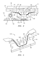
FIG. 5 is a perspective illustration of an alternate embodiment leaf spring damper. -
FIG. 1 illustrates a portion of a gasturbine engine augmentor 10. Theaugmentor 10 includes atrailing edge box 12, aspray bar assembly 14 and aflame holder assembly 16. - The
trailing edge box 12 includes aninner box cavity 18 that extends radially between a radialinner endwall 20 and a radialouter endwall 22. Theinner box cavity 18 extends laterally (e.g., circumferentially) between afirst box sidewall 24 and asecond box sidewall 26. Theinner box cavity 18 also extends axially from a turbineexhaust case strut 28 to a trailingedge box aperture 30. - The
spray bar assembly 14 extends longitudinally (e.g., radially and axially) between a firstspray bar end 32 and a secondspray bar end 34. Thespray bar assembly 14 may include one ormore fuel conduits bar nozzle assemblies 40. Each spraybar nozzle assembly 40 may include anozzle 42 that extends laterally from a respective one of thefuel conduits injector wear block 44. Referring toFIG. 2 , eachinjector wear block 44 may include a wear block flat, e.g., 46 or 48. An example of an alternative spray bar assembly configuration is disclosed inU.S. Patent Nos. 7,647,775 and7,578,131 . - Referring to
FIG. 3 , theflame holder assembly 16 may include a mounting platform 50 (e.g., an impingement sheet assembly), one ormore attachment lugs 52, and aleaf spring damper 54. Themounting platform 50 has amounting surface 56 that extends longitudinally between a first platform endwall 58 (e.g., a radial inner endwall) and a second platform endwall 60 (e.g., a radial outer endwall). Themounting surface 56 also extends laterally between afirst platform sidewall 62 and asecond platform sidewall 64. An example of an attachment lug is disclosed inU.S. Patent Application Serial No. 12/112,470 . - The
leaf spring damper 54 includes astack 66 of a plurality of leaf springs. Thestack 66 illustrated inFIG. 2 , for example, includes afirst leaf spring 68, asecond leaf spring 70 and athird leaf spring 72. Thestack 66 extends longitudinally between afirst stack end 74 and asecond stack end 76. Thestack 66 may include abase segment 78, a first spraybar contact segment 80, a second spraybar contact segment 82, afirst transition segment 84 and asecond transition segment 86. Thebase segment 78 is connected longitudinally between the first spraybar contact segment 80 and the second spraybar contact segment 82, and extends longitudinally between thefirst transition segment 84 and thesecond transition segment 86. The first spraybar contact segment 80 extends longitudinally between thefirst transition segment 84 and thefirst stack end 74. The second spraybar contact segment 82 extends longitudinally between thesecond transition segment 86 and thesecond stack end 76. Thefirst transition segment 84 and thesecond transition segment 86 may each have a (e.g., compound) curved and/or stepped sectional geometry. - Referring to
FIG. 4 , thebase segment 78 has a lateralbase segment width 88. The first spraybar contact segment 80 and the second spraybar contact segment 82 each have a respective lateralcontact segment width first transition segment 84 and thesecond transition segment 86 each have a respective lateraltransition segment width base segment width 88 may be greater than each of thetransition segment widths contact segment widths transition segment widths - The
first leaf spring 68 may extend longitudinally between thefirst stack end 74 and thesecond stack end 76. Thefirst leaf spring 68 may also extend laterally, in thebase segment 78, between an anti-rotationfirst flange 98 and an anti-rotationsecond flange 100. Thefirst flange 98 and thesecond flange 100 may each extend transversely (e.g., radially and axially) from thefirst leaf spring 68 to a respectivedistal end 102, 104 (see alsoFIG. 2 ). Referring toFIG. 2 , thesecond leaf spring 70 may extend longitudinally between the first spraybar contact segment 80 and the second spraybar contact segment 82 and, for example, partially into the first spraybar contact segment 80 and the second spraybar contact segment 82. Thethird leaf spring 72 may extend longitudinally between the first spraybar contact segment 80 and the second spraybar contact segment 82. Referring toFIG. 4 , thethird leaf spring 72 may also extend laterally, in thebase segment 78, between afirst mounting flange 106 and asecond mounting flange 108, which may collectively form adamper mounting bracket 110. Thefirst mounting flange 106 and thesecond mounting flange 108 may each respectively include afirst flange segment second flange segment first flange segment third leaf spring 72 to thesecond flange segment second flange segment first flange segment distal flange end - Referring to
FIGS. 2 and3 , thesecond leaf spring 70 may be stacked between thethird leaf spring 72 and thefirst leaf spring 68. Thesecond leaf spring 70 and thedamper mounting bracket 110 may be seated (e.g., nested) between thefirst flange 98 and thesecond flange 100. At least one fastener 124 (e.g., a single rivet) may connect thefirst leaf spring 68, thesecond leaf spring 70 and thethird leaf spring 72 together. Thefirst flange 98 and thesecond flange 100 may reduce (or prevent) relative rotation between thedamper mounting bracket 110 and thefirst leaf spring 68 and/or thesecond leaf spring 70 during engine operation. - Referring to
FIG. 3 , thesecond flange segments surface 56 with, for example, a plurality of fasteners 126 (e.g., rivets). Each of the attachment lugs 52 may also be connected to the mountingsurface 56 with, for example, a plurality of fasteners 128 (e.g., rivets). - Referring to
FIG. 1 , thespray bar assembly 14 is arranged within theinner box cavity 18, and the firstspray bar end 32 may be connected to the radialinner endwall 20. The mountingplatform 50 may be mated with the trailingedge box aperture 30, and connected to the trailingedge box 12 using the attachment lugs 52. Referring toFIG. 2 , the first spraybar contact segment 80 engages (e.g., contacts) and, for example, exerts a spring preload against the wear block flat 46. The second spraybar contact segment 82 engages and, for example, exerts a spring preload against the wear block flat 48. The spring preloads may be selected, for example, such that thecontact segments spray bar assembly 14 throughout engine operation. - The
base segment 78 is located a non-zerofirst distance 129 from thespray bar assembly 14. The first spraybar contact segment 80 is located a non-zerosecond distance 130 from the mountingsurface 56, and the second spraybar contact segment 82 is located a non-zerothird distance 132 from the mountingsurface 56. The first spraybar contact segment 80 and the second spraybar contact segment 82 therefore are in spaced relationship to and may move transversely relative to thebase segment 78 and the mountingsurface 56 and, thus, may damp vibrations within thespray bar assembly 14 during engine operation. The damping may be provided from the flexing of thefirst transition segment 84 and/or thesecond transition segment 86, and/or from frictional sliding between the adjacent leaf springs (e.g., between 68 and 70, and/or 70 and 72). - In some embodiments, one or more of the leaf springs in the stack may have a different spring constant (also referred to as a spring rate); i.e., k (Newton/meters). In other embodiments, a plurality of the leaf springs may have substantially equal spring constants.
- In some embodiments, a plurality of the leaf springs in the stack may have similar geometrical configurations.
-
FIG. 5 is a perspective illustration of an alternate embodimentleaf spring damper 134. In contrast to theleaf spring damper 54 illustrated inFIG. 2 , theleaf spring damper 134 may be connected to and may contact the mounting platform 50 (e.g., without a damper mounting bracket). Abase segment 136 of theleaf spring damper 134 stack, for example, may be fastened to the mountingsurface 56 with a plurality of fasteners 138 (e.g., rivets). Thefasteners 138 may also serve to reduce (or prevent) relative rotation between theleaf springs platform 50. In addition, awidth 146 of thebase segment 136 may be substantially equal to thetransition segment widths - While various embodiments of the present invention have been disclosed, it will be apparent to those of ordinary skill in the art that many more embodiments and implementations are possible within the scope of the invention. Accordingly, the present invention is not to be restricted except in light of the attached claims and their equivalents.
Claims (15)
- A fuel delivery system for a gas turbine engine, comprising:a mounting platform (50);a spray bar assembly (40); anda leaf spring damper (54) comprising a stack (66) of a plurality of leaf springs (68, 70, 72), the stack (66) comprising a base segment (78) connected longitudinally between a first spray bar contact segment (80) and a second spray bar contact segment (82), wherein the base segment (78) is connected to the mounting platform (50) and is located a first distance (129) from the spray bar assembly (40), the first spray bar contact segment (80) engages the spray bar assembly (40) and is located a second distance (130) from the mounting platform (50), and the second spray bar contact segment (82) engages the spray bar assembly (40) and is located a third distance (132) from the mounting platform (50).
- The system of claim 1, wherein the stack (66) further comprises a first transition segment (84) extending between the base segment (78) and the first spray bar contact segment (80), and a second transition segment (86) extending between the base segment (78) and the second spray bar contact segment (82).
- The system of claim 2, wherein a width (90) of the first spray bar contact segment (80) is greater than a width (94) of the first transition segment (84), and a width (92) of the second spray bar contact segment (82) is greater than a width (96) of the second transition segment (86).
- The system of claim 2 or 3, wherein a width (88) of the base segment (78) is greater than a width (94) of the first transition segment (84) and a width (96) of the second transition segment (86).
- The system of any preceding claim, wherein the stack (66) extends longitudinally between a first stack end (74) and a second stack end (76), and wherein the plurality of leaf springs (68, 70, 72) comprise a first leaf spring (68) that extends between the first stack end (74) and the second stack end (76), and a second leaf spring (70) that extends partially into and between the first spray bar contact segment (80) and the second spray bar contact segment (82), and optionally, wherein the plurality of leaf springs (68, 70, 72) further comprise a third leaf spring (72) that extends between the first spray bar contact segment (80) and the second spray bar contact segment (82).
- The system of any of claims 1 to 4, wherein the stack (66) extends longitudinally between a first stack end (74) and a second stack end (76), and wherein the plurality of leaf springs (68, 70, 72) comprise a first leaf spring (68) that extends between the first stack end (74) and the second stack end (76), and a second leaf spring (70) that extends between the first spray bar contact segment (80) and the second spray bar contact segment (82).
- The system of any preceding claim, wherein the plurality of leaf springs (68, 70, 72) comprise a first leaf spring (68) and a second leaf spring (70), the first leaf spring (68) extending laterally in the base segment (78) between a first flange (98) and a second flange (100), and wherein the second leaf spring (70) is seated between the first flange (98) and the second flange (100), and optionally, wherein the leaf spring damper (54) further comprises a mounting bracket (110) that connects the base segment (68) to the mounting platform (50), and that is seated between the first flange (98) and the second flange (100).
- The system of any preceding claim, wherein the plurality of leaf springs (68, 70, 72) are connected together with a single fastener (124).
- The system of any preceding claim, wherein the base segment (78) contacts the mounting platform (50).
- The system of any preceding claim, wherein the leaf spring damper (54) further comprises a mounting bracket that connects the base segment (78) to the mounting platform (50), and optionally wherein the plurality of leaf springs (68, 70, 72) comprises a first leaf spring (68) and a second leaf spring (72) that extends laterally in the base segment (68) between a first mounting flange (106) and a second mounting flange (108), and wherein the first mounting flange (106) and the second mounting flange (108) form the mounting bracket (110).
- The system of any preceding claim, wherein the spray bar assembly (40) comprises a first injector wear block (46) and a second injector wear block (48), and wherein the first spray bar contact segment (80) contacts the first injector wear block (46), and the second spray bar contact segment (82) contacts the second injector wear block (48).
- The system of any preceding claim, further comprising a flame holder assembly (16) that includes the mounting platform (50), and optionally wherein the flame holder assembly (16) is connected to a turbine engine augmentor trailing edge box (12).
- A gas turbine engine augmentor (10), comprising:a flame holder (16) comprising a mounting platform (50);a spray bar assembly (40); anda leaf spring damper (54) comprising a stack (66) of a plurality of leaf springs (68, 70, 72), the stack (66) comprising a base segment (78) connected longitudinally between a first spray bar contact segment (80) and a second spray bar contact segment (82), wherein the base segment (78) is connected to the mounting platform (50) and is arranged in spaced relationship to the spray bar assembly (40), the first spray bar contact segment (80) engages the spray bar assembly (40) and is arranged in spaced relationship to the mounting platform (50), and the second spray bar contact segment (82) engages the spray bar assembly (40) and is arranged in spaced relationship to the mounting platform (50).
- The system of claim 13, wherein the stack (66) further comprises a first transition segment (84) extending between the base segment (78) and the first spray bar contact segment (80), and a second transition segment (86) extending between the base segment (78) and the second spray bar contact segment (82).
- The system of claim 13 or 14, wherein the stack extends (66) longitudinally between a first stack end (74) and a second stack end (76), and wherein the plurality of leaf springs (68, 70, 72) comprise a first leaf spring (68) that extends between the first stack end (74) and the second stack end (76), and a second leaf spring (70) that extends partially into and between the first spray bar contact segment (80) and the second spray bar contact segment (82), and optionally wherein the plurality of leaf springs (66) further comprise a third leaf spring (72) that extends between the first spray bar contact segment (80) and the second spray bar contact segment (82).
Applications Claiming Priority (1)
| Application Number | Priority Date | Filing Date | Title |
|---|---|---|---|
| US13/312,621 US9140213B2 (en) | 2011-12-06 | 2011-12-06 | Leaf spring damper for a turbine engine fuel delivery system |
Publications (1)
| Publication Number | Publication Date |
|---|---|
| EP2602548A1 true EP2602548A1 (en) | 2013-06-12 |
Family
ID=47142924
Family Applications (1)
| Application Number | Title | Priority Date | Filing Date |
|---|---|---|---|
| EP20120187510 Withdrawn EP2602548A1 (en) | 2011-12-06 | 2012-10-05 | Leaf spring damper for a turbine engine fuel delivery system |
Country Status (2)
| Country | Link |
|---|---|
| US (1) | US9140213B2 (en) |
| EP (1) | EP2602548A1 (en) |
Families Citing this family (5)
| Publication number | Priority date | Publication date | Assignee | Title |
|---|---|---|---|---|
| IL286427B2 (en) * | 2014-01-28 | 2024-08-01 | Mayo Found Medical Education & Res | BCL-2 ANTI-APOPTOTIC PROTEIN FAMILY MEMBERS inhibitors for the treatment of a non-cancerous disease or a disease of the eye |
| US10041444B2 (en) | 2014-09-05 | 2018-08-07 | United Technologies Corporation | Variable orifice jet for a turbine engine |
| US10280791B2 (en) | 2016-07-11 | 2019-05-07 | United Technologies Corporation | Tuned mass damper for tubes |
| US10808788B2 (en) | 2017-04-07 | 2020-10-20 | General Electric Company | Damper for a fuel delivery system |
| US11473431B2 (en) | 2019-03-12 | 2022-10-18 | Raytheon Technologies Corporation | Energy dissipating damper |
Citations (5)
| Publication number | Priority date | Publication date | Assignee | Title |
|---|---|---|---|---|
| US20070006590A1 (en) * | 2005-06-30 | 2007-01-11 | Muldoon Marc J | Augmentor spray bars |
| US20070214793A1 (en) * | 2006-03-14 | 2007-09-20 | United Technologies Corporation | Structural track support of spraybars/tubing |
| US7578131B2 (en) | 2005-06-30 | 2009-08-25 | United Technologies Corporation | Augmentor spray bar mounting |
| US20090272123A1 (en) * | 2008-04-30 | 2009-11-05 | United Technologies Corp. | Gas Turbine Engine Systems and Related Methods Involving Thermally Isolated Retention |
| US11247008B1 (en) | 2020-08-05 | 2022-02-15 | Effortless Oxygen, Llc | Flow triggered gas delivery |
Family Cites Families (14)
| Publication number | Priority date | Publication date | Assignee | Title |
|---|---|---|---|---|
| US5287697A (en) * | 1992-01-02 | 1994-02-22 | General Electric Company | Variable area bypass injector seal |
| DE10017643B4 (en) | 2000-04-08 | 2005-10-20 | Mtu Aero Engines Gmbh | Seal in non-hermetic design |
| GB0108398D0 (en) | 2001-04-04 | 2001-05-23 | Siemens Ag | Seal element for sealing a gap and combustion turbine having a seal element |
| US6733233B2 (en) | 2002-04-26 | 2004-05-11 | Pratt & Whitney Canada Corp. | Attachment of a ceramic shroud in a metal housing |
| DE102005023354A1 (en) | 2004-06-29 | 2006-01-26 | Zf Friedrichshafen Ag | Pressure plate assembly, clutch disc assembly and friction clutch, in particular multi-plate clutch |
| US8015996B2 (en) | 2005-04-28 | 2011-09-13 | United Technologies Corporation | Gas turbine engine air valve assembly |
| US7966819B2 (en) * | 2006-09-26 | 2011-06-28 | Parker-Hannifin Corporation | Vibration damper for fuel injector |
| US7854124B2 (en) | 2006-10-27 | 2010-12-21 | United Technologies Corporation | Combined control for supplying cooling air and support air in a turbine engine nozzle |
| US7806410B2 (en) * | 2007-02-20 | 2010-10-05 | United Technologies Corporation | Damping device for a stationary labyrinth seal |
| FR2920524B1 (en) * | 2007-08-30 | 2013-11-01 | Snecma | TURBOMACHINE WITH ANNULAR COMBUSTION CHAMBER |
| EP2247830B1 (en) * | 2008-02-27 | 2019-04-10 | General Electric Company | Flexible seal for a turbine and corresponding turbine |
| US8517687B2 (en) | 2010-03-10 | 2013-08-27 | United Technologies Corporation | Gas turbine engine compressor and turbine section assembly utilizing tie shaft |
| US9046038B2 (en) * | 2012-08-31 | 2015-06-02 | General Electric Company | Combustor |
| US20140223919A1 (en) * | 2013-02-14 | 2014-08-14 | United Technologies Corporation | Flexible liner hanger |
-
2011
- 2011-12-06 US US13/312,621 patent/US9140213B2/en active Active
-
2012
- 2012-10-05 EP EP20120187510 patent/EP2602548A1/en not_active Withdrawn
Patent Citations (6)
| Publication number | Priority date | Publication date | Assignee | Title |
|---|---|---|---|---|
| US20070006590A1 (en) * | 2005-06-30 | 2007-01-11 | Muldoon Marc J | Augmentor spray bars |
| US7578131B2 (en) | 2005-06-30 | 2009-08-25 | United Technologies Corporation | Augmentor spray bar mounting |
| US7647775B2 (en) | 2005-06-30 | 2010-01-19 | United Technologies Corporation | Augmentor spray bars |
| US20070214793A1 (en) * | 2006-03-14 | 2007-09-20 | United Technologies Corporation | Structural track support of spraybars/tubing |
| US20090272123A1 (en) * | 2008-04-30 | 2009-11-05 | United Technologies Corp. | Gas Turbine Engine Systems and Related Methods Involving Thermally Isolated Retention |
| US11247008B1 (en) | 2020-08-05 | 2022-02-15 | Effortless Oxygen, Llc | Flow triggered gas delivery |
Also Published As
| Publication number | Publication date |
|---|---|
| US20130139512A1 (en) | 2013-06-06 |
| US9140213B2 (en) | 2015-09-22 |
Similar Documents
| Publication | Publication Date | Title |
|---|---|---|
| US8631578B2 (en) | Radial balancing clip weight for rotor assembly | |
| EP3415724B1 (en) | Resilient mounting assembly for a turbine engine | |
| JP5551758B2 (en) | Stator assembly, manufacturing method thereof, and damper spring | |
| US8186961B2 (en) | Blade preloading system | |
| KR101428871B1 (en) | A spring damper, a stator assembly, and a method of manufacturing the same | |
| EP2800903B1 (en) | Blade track apparatus and method of assembling a blade track apparatus | |
| US8951013B2 (en) | Turbine blade rail damper | |
| US9151165B2 (en) | Reversible blade damper | |
| EP2602548A1 (en) | Leaf spring damper for a turbine engine fuel delivery system | |
| CA2638542C (en) | Radial loading element for turbine vane | |
| US20070237632A1 (en) | Foreign object damage resistant vane assembly | |
| US10385707B2 (en) | Turbine disc interstage coupling with retention ring features | |
| CN111911242B (en) | Turbine module and aircraft turbine comprising a turbine module | |
| US8920116B2 (en) | Wear prevention system for securing compressor airfoils within a turbine engine | |
| US9074479B2 (en) | Damping element and method for damping rotor blade vibrations, a rotor blade, and a rotor | |
| US10450866B2 (en) | Rotor device of an aircraft engine with a damping device between turbines blades | |
| US20140255187A1 (en) | Attachment feature of a gas turbine engine blade having a curved profile | |
| US10329929B2 (en) | Retaining ring axially loaded against segmented disc surface | |
| US11084150B2 (en) | Wear liner installation tool | |
| US8567745B2 (en) | Apparatuses and systems with vertically and longitudinally offset mounting flanges | |
| US9546571B2 (en) | Mounting lug for connecting a vane to a turbine engine case | |
| US7771164B2 (en) | Method and system for assembling a turbine engine | |
| US10767503B2 (en) | Stator assembly with retention clip for gas turbine engine | |
| US10400615B2 (en) | Retaining ring groove submerged into disc bore or hub | |
| US20140223919A1 (en) | Flexible liner hanger |
Legal Events
| Date | Code | Title | Description |
|---|---|---|---|
| PUAI | Public reference made under article 153(3) epc to a published international application that has entered the european phase |
Free format text: ORIGINAL CODE: 0009012 |
|
| AK | Designated contracting states |
Kind code of ref document: A1 Designated state(s): AL AT BE BG CH CY CZ DE DK EE ES FI FR GB GR HR HU IE IS IT LI LT LU LV MC MK MT NL NO PL PT RO RS SE SI SK SM TR |
|
| AX | Request for extension of the european patent |
Extension state: BA ME |
|
| STAA | Information on the status of an ep patent application or granted ep patent |
Free format text: STATUS: THE APPLICATION IS DEEMED TO BE WITHDRAWN |
|
| 18D | Application deemed to be withdrawn |
Effective date: 20131213 |