EP2602435A2 - Turbomachine rotor and corresponding assembly method - Google Patents
Turbomachine rotor and corresponding assembly method Download PDFInfo
- Publication number
- EP2602435A2 EP2602435A2 EP12195723.7A EP12195723A EP2602435A2 EP 2602435 A2 EP2602435 A2 EP 2602435A2 EP 12195723 A EP12195723 A EP 12195723A EP 2602435 A2 EP2602435 A2 EP 2602435A2
- Authority
- EP
- European Patent Office
- Prior art keywords
- rotor
- rails
- turbomachine
- blade
- slots
- Prior art date
- Legal status (The legal status is an assumption and is not a legal conclusion. Google has not performed a legal analysis and makes no representation as to the accuracy of the status listed.)
- Granted
Links
Images


Classifications
-
- F—MECHANICAL ENGINEERING; LIGHTING; HEATING; WEAPONS; BLASTING
- F01—MACHINES OR ENGINES IN GENERAL; ENGINE PLANTS IN GENERAL; STEAM ENGINES
- F01D—NON-POSITIVE DISPLACEMENT MACHINES OR ENGINES, e.g. STEAM TURBINES
- F01D5/00—Blades; Blade-carrying members; Heating, heat-insulating, cooling or antivibration means on the blades or the members
- F01D5/30—Fixing blades to rotors; Blade roots ; Blade spacers
- F01D5/32—Locking, e.g. by final locking blades or keys
-
- F—MECHANICAL ENGINEERING; LIGHTING; HEATING; WEAPONS; BLASTING
- F01—MACHINES OR ENGINES IN GENERAL; ENGINE PLANTS IN GENERAL; STEAM ENGINES
- F01D—NON-POSITIVE DISPLACEMENT MACHINES OR ENGINES, e.g. STEAM TURBINES
- F01D5/00—Blades; Blade-carrying members; Heating, heat-insulating, cooling or antivibration means on the blades or the members
- F01D5/30—Fixing blades to rotors; Blade roots ; Blade spacers
- F01D5/3023—Fixing blades to rotors; Blade roots ; Blade spacers of radial insertion type, e.g. in individual recesses
- F01D5/303—Fixing blades to rotors; Blade roots ; Blade spacers of radial insertion type, e.g. in individual recesses in a circumferential slot
- F01D5/3038—Fixing blades to rotors; Blade roots ; Blade spacers of radial insertion type, e.g. in individual recesses in a circumferential slot the slot having inwardly directed abutment faces on both sides
-
- Y—GENERAL TAGGING OF NEW TECHNOLOGICAL DEVELOPMENTS; GENERAL TAGGING OF CROSS-SECTIONAL TECHNOLOGIES SPANNING OVER SEVERAL SECTIONS OF THE IPC; TECHNICAL SUBJECTS COVERED BY FORMER USPC CROSS-REFERENCE ART COLLECTIONS [XRACs] AND DIGESTS
- Y10—TECHNICAL SUBJECTS COVERED BY FORMER USPC
- Y10T—TECHNICAL SUBJECTS COVERED BY FORMER US CLASSIFICATION
- Y10T29/00—Metal working
- Y10T29/49—Method of mechanical manufacture
- Y10T29/49316—Impeller making
- Y10T29/4932—Turbomachine making
- Y10T29/49321—Assembling individual fluid flow interacting members, e.g., blades, vanes, buckets, on rotary support member
Definitions
- This disclosure relates to a tangential compressor or turbine rotor having relief features formed on one of the two rails in the rotor and load slots formed on the other of the two rails in the rotor.
- Turbomachines such as gas turbine engines, are known. Turbomachines typically include a compressor that compresses air and delivers it downstream into a combustion section. The compressed air is mixed with fuel and combusted. The products of combustion pass downstream through a turbine.
- the compressor and turbine include rotors. Arrays of removable blades are mounted to the rotors.
- the removable blades When mounting the removable blades to the rotor, the removable blades are moved into load slots formed in the two opposed rails in the rotor.
- the load slots are formed at circumferentially spaced locations.
- Each of the load slots extend radially from radially inward facing surfaces of the rails to radially outward facing surfaces of the rails.
- the blades are then slid into a mount space between the rails, at locations that are circumferentially offset from the load slots.
- the blades are moved circumferentially until they fill the entire space.
- locks are positioned at several circumferentially spaced locations between the blades to take up remaining space and inhibit the blades from moving circumferentially relative to the rotor.
- circumferentially aligned pairs of load slots are formed in the opposing rails to accommodate the roots of the blades.
- Some prior art designs may utilize a single load slot formed in the rail that faces the compressor rather than a circumferentially aligned pair of load slots.
- the single load slot is much larger than each of the load slots in the circumferentially aligned pairs.
- the larger load slot may undesirably accelerate fatigue in the rail.
- An exemplary turbomachine rotor assembly includes a pair of spaced rails that extend around a cylindrical surface to define a rotor hub.
- the rails define a space for receiving blades.
- Load slots are formed in one of the rails.
- a relief feature is formed in an opposite surface of an opposing rail. The load slots and relief feature are utilized to move at least one of the blades into the space.
- Another example turbomachine rotor assembly includes a pair of spaced rails that extend around a cylindrical surface to define a rotor hub.
- the rails define a space for receiving blades.
- Blade load slots are formed in one of the rails.
- the blade load slots extend from an outwardly facing surface of the one of the rails to an inwardly facing surface of the other of the rails.
- Relief features are formed on an underside of the opposed rail. The relief feature is circumferentially aligned with the blade load slots. The blades are moved into the space through the blade load slots and the relief feature. The blades are then moved circumferentially to be adjacent to other blades.
- a rotor assembly method includes moving a blade into a space between a pair of spaced rails that extend around a cylindrical surface to define a rotor hub. The method then moves the blade circumferentially to an installed position within the rotor hub. The blade moves through a blade load slot formed on one of the spaced rails, and through a relief feature formed on the other of the spaced rails.
- FIG. 1 schematically shows a turbine rotor 20 for use in a gas turbine engine or another type of turbomachine.
- the rotor 20 incorporates a rotor hub 22, and an array of blades 24 spaced about the circumference of the rotor hub 22.
- the rotor hub 22 is centered for rotation about a central axis X, as is known. While the example embodiments will be described with reference to a turbine rotor, other examples have application in a compressor rotor.
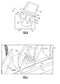
- a blade 26 in the array 24 is mounted between rear rail 34 and forward rail 38, through a load slot 42.
- the rear rail 34 and forward rail 38 together make up a pair of spaced rails.
- the load slot 42 is formed in the "cold side” forward rail 38, and is not formed in the "hot side” rear rail 34.
- the "cold side” forward rail 38 may be further from a combustion section C than the "hot side” rear rail 34 when the rotor 20 is mounted within a gas turbine engine. While the "hot side” will typically face toward the combustion section, in certain applications, and at certain turbine stages, it is possible for the opposed “upstream” side of the turbine to be the hot side. Further, when the features of this disclosure are applied to a compressor rotor, the hot side may also be facing toward the combustion section, or away, depending on the particular application.
- the blade has a root section 46 having a forward ear 48, which is received under the forward rail 38, and a rear ear 50, which moves through the load slot 42.
- a relief feature 52 is formed in the underside of the rear rail 34.
- the relief feature 52 facilitates movement of the root section 46, and particularly the rear ear 50, through the load slot 42.
- the load slot 42 does not need to be as large. That is, the load slot 42 can be made shallower because of the relief feature 52 accommodating some of the root section 46 during installation.
- the load slot 42 is formed in the forward rail 38, and there is no corresponding slot in the rear rail 34.
- the relief feature 52 does correspond to the circumferential location of the load slot 42.
- the forward rail 38 is formed with lock slots 56, while the rear rail 34 does not have any such lock slots 56.
- the rear rail 34 includes a radially outward facing surface 60 and a radially inward facing surface 62 that meet at an interface 64.
- the example relief feature 52 is formed entirely within the radially inward facing surface 62 and does not extend past the interface 64. That is, there is no portion of the relief feature 52 extending into the radially outward facing surface 60.
- the radially outward facing surface 60 is continuous and uninterrupted about the entire circumference of the rear rail 34.
- the relief feature 52 is concave.
- the load slot 42 in contrast to the relief feature 52, does extend from an outwardly facing surface of the forward rail 38 to an inwardly facing surface of the forward rail 38.
- the forward ear 48 when initially mounting the blade 26 within the rotor hub 22, the forward ear 48 is rotated into the load slot 42 about a back edge 66 of the blade 26 in a direction P.
- the relief feature 52 provides room for the rear ear 50 of the root section 46.
- the forward ear 48 may be "hooked" under a ladder seal (not shown) during installation.
- the blade 22 can be moved circumferentially, with the ears 48 and 50 remaining underneath portions of the forward rail 38 and rear rail 34, such that the blades 26 can be aligned and positioned across the entire circumference of the rotor 20 (see Figure 1 ).
- the forward rail 38 and rear rail 34 define a space to receive and mount the blades 26.
- FIG. 7 shows another detail, wherein blades 26 have been mounted between the forward rail 38 and rear rail 34. In addition, other blades 26 are shown, which have a space to surround a lock member 70.
- Lock members 70 are typically positioned on each side of a pair of blades 26 that sit circumferentially closest to the load slot 42 when the rotor 20 is fully assembled with blades 26. In addition, other lock members 70 are provided at circumferentially spaced locations.
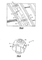
- the locks 70 are received with a curved side 74 sitting in the lock slot 56, and a relatively flat side 78 facing the rear rail 34.
- Figure 9 shows the lock member 70 having a flat side 78, the curved side 74, and receiving a lock pin, or set screw 82, which is tightened to secure the lock member 70 within the rotor hub 22 once the rotor 20 is fully assembled.
- the curved (or barrel) side 74 is on one side of the lock member 70, with the relatively flat side 78 on the opposite side.
- Flat side walls 86 extend between the curved side 74 and the flat side 78.
- features of the disclosed examples include incorporating a relief feature on an aft rail to enable making the load slot on the forward rail shallower.
- the relief feature helps balance fatigue life between the two rails. Unlike the load slot, the relief feature does not penetrate the top of the aft rail, which keeps stress concentrations in a lower temperature and lower stress area.
Landscapes
- Engineering & Computer Science (AREA)
- Mechanical Engineering (AREA)
- General Engineering & Computer Science (AREA)
- Structures Of Non-Positive Displacement Pumps (AREA)
- Turbine Rotor Nozzle Sealing (AREA)
Abstract
Description
- This disclosure relates to a tangential compressor or turbine rotor having relief features formed on one of the two rails in the rotor and load slots formed on the other of the two rails in the rotor.
- Turbomachines, such as gas turbine engines, are known. Turbomachines typically include a compressor that compresses air and delivers it downstream into a combustion section. The compressed air is mixed with fuel and combusted. The products of combustion pass downstream through a turbine. The compressor and turbine include rotors. Arrays of removable blades are mounted to the rotors.
- When mounting the removable blades to the rotor, the removable blades are moved into load slots formed in the two opposed rails in the rotor. The load slots are formed at circumferentially spaced locations. Each of the load slots extend radially from radially inward facing surfaces of the rails to radially outward facing surfaces of the rails. During installation, the relatively wide root of each individual blade is moved into the load slots. The blades are then slid into a mount space between the rails, at locations that are circumferentially offset from the load slots. The blades are moved circumferentially until they fill the entire space. In addition, locks are positioned at several circumferentially spaced locations between the blades to take up remaining space and inhibit the blades from moving circumferentially relative to the rotor.
- In the prior art, circumferentially aligned pairs of load slots are formed in the opposing rails to accommodate the roots of the blades. Some prior art designs may utilize a single load slot formed in the rail that faces the compressor rather than a circumferentially aligned pair of load slots. The single load slot is much larger than each of the load slots in the circumferentially aligned pairs. The larger load slot may undesirably accelerate fatigue in the rail.
- An exemplary turbomachine rotor assembly includes a pair of spaced rails that extend around a cylindrical surface to define a rotor hub. The rails define a space for receiving blades. Load slots are formed in one of the rails. A relief feature is formed in an opposite surface of an opposing rail. The load slots and relief feature are utilized to move at least one of the blades into the space.
- Another example turbomachine rotor assembly includes a pair of spaced rails that extend around a cylindrical surface to define a rotor hub. The rails define a space for receiving blades. Blade load slots are formed in one of the rails. The blade load slots extend from an outwardly facing surface of the one of the rails to an inwardly facing surface of the other of the rails. Relief features are formed on an underside of the opposed rail. The relief feature is circumferentially aligned with the blade load slots. The blades are moved into the space through the blade load slots and the relief feature. The blades are then moved circumferentially to be adjacent to other blades.
- A rotor assembly method includes moving a blade into a space between a pair of spaced rails that extend around a cylindrical surface to define a rotor hub. The method then moves the blade circumferentially to an installed position within the rotor hub. The blade moves through a blade load slot formed on one of the spaced rails, and through a relief feature formed on the other of the spaced rails.
- The various features and advantages of the disclosed examples will become apparent to those skilled in the art from the detailed description. The figures that accompany the detailed description can be briefly described as follows:
-
Figure 1 shows the mounting of a blade within a turbine rotor. -
Figure 2 shows a portion of theFigure 1 turbine rotor and a blade insertion step. -
Figure 3 shows a perspective view of a portion of theFigure 1 turbine rotor. -
Figure 4 shows another perspective view of a portion of theFigure 1 turbine rotor. -
Figure 5 shows yet another perspective view of a portion of theFigure 1 turbine rotor. -
Figure 6 shows a portion of theFigure 1 turbine rotor and a blade insertion step that is earlier than the blade insertion step shown inFigure 2 . -
Figure 7 shows lock members of theFigure 1 turbine rotor. -
Figure 8 shows another feature of the lock members. -
Figure 9 shows another detail of the lock member. -
Figure 1 schematically shows aturbine rotor 20 for use in a gas turbine engine or another type of turbomachine. Therotor 20 incorporates arotor hub 22, and an array of blades 24 spaced about the circumference of therotor hub 22. Therotor hub 22 is centered for rotation about a central axis X, as is known. While the example embodiments will be described with reference to a turbine rotor, other examples have application in a compressor rotor. - As shown in
Figures 2-4 , ablade 26 in the array 24 is mounted betweenrear rail 34 andforward rail 38, through aload slot 42. Therear rail 34 andforward rail 38 together make up a pair of spaced rails. - The
load slot 42 is formed in the "cold side"forward rail 38, and is not formed in the "hot side"rear rail 34. The "cold side"forward rail 38 may be further from a combustion section C than the "hot side"rear rail 34 when therotor 20 is mounted within a gas turbine engine. While the "hot side" will typically face toward the combustion section, in certain applications, and at certain turbine stages, it is possible for the opposed "upstream" side of the turbine to be the hot side. Further, when the features of this disclosure are applied to a compressor rotor, the hot side may also be facing toward the combustion section, or away, depending on the particular application. - As shown, the blade has a
root section 46 having aforward ear 48, which is received under theforward rail 38, and arear ear 50, which moves through theload slot 42. - A
relief feature 52 is formed in the underside of therear rail 34. Therelief feature 52 facilitates movement of theroot section 46, and particularly therear ear 50, through theload slot 42. - Due to the
relief feature 52, theload slot 42 does not need to be as large. That is, theload slot 42 can be made shallower because of therelief feature 52 accommodating some of theroot section 46 during installation. - The
load slot 42 is formed in theforward rail 38, and there is no corresponding slot in therear rail 34. Therelief feature 52, however, does correspond to the circumferential location of theload slot 42. In addition, as shown inFigure 3 , theforward rail 38 is formed withlock slots 56, while therear rail 34 does not have anysuch lock slots 56. - The
rear rail 34 includes a radially outward facingsurface 60 and a radially inward facingsurface 62 that meet at aninterface 64. Theexample relief feature 52 is formed entirely within the radially inward facingsurface 62 and does not extend past theinterface 64. That is, there is no portion of therelief feature 52 extending into the radially outward facingsurface 60. In this example, the radially outward facingsurface 60 is continuous and uninterrupted about the entire circumference of therear rail 34. Also, in this example, therelief feature 52 is concave. - The
load slot 42, in contrast to therelief feature 52, does extend from an outwardly facing surface of theforward rail 38 to an inwardly facing surface of theforward rail 38. - As shown in
Figures 2 and6 , when initially mounting theblade 26 within therotor hub 22, theforward ear 48 is rotated into theload slot 42 about aback edge 66 of theblade 26 in a direction P. Therelief feature 52 provides room for therear ear 50 of theroot section 46. Theforward ear 48 may be "hooked" under a ladder seal (not shown) during installation. - After the
blade 26 is fully rotated into theload slot 42, theblade 22 can be moved circumferentially, with theears forward rail 38 andrear rail 34, such that theblades 26 can be aligned and positioned across the entire circumference of the rotor 20 (seeFigure 1 ). In applications, there may be twoload slots 42 spaced by 180° about the circumference of therotor hub 22. Essentially, theforward rail 38 andrear rail 34 define a space to receive and mount theblades 26. -
Figure 7 shows another detail, whereinblades 26 have been mounted between theforward rail 38 andrear rail 34. In addition,other blades 26 are shown, which have a space to surround alock member 70. -
Lock members 70 are typically positioned on each side of a pair ofblades 26 that sit circumferentially closest to theload slot 42 when therotor 20 is fully assembled withblades 26. In addition,other lock members 70 are provided at circumferentially spaced locations. - In this example, there are a total of eight locks, spaced evenly about the circumference of the
rotor 20, but with two sets of locks secured on each side of theload slot 42. - As shown in
Figure 8 , thelocks 70 are received with acurved side 74 sitting in thelock slot 56, and a relativelyflat side 78 facing therear rail 34. -
Figure 9 shows thelock member 70 having aflat side 78, thecurved side 74, and receiving a lock pin, or setscrew 82, which is tightened to secure thelock member 70 within therotor hub 22 once therotor 20 is fully assembled. - As shown, the curved (or barrel)
side 74 is on one side of thelock member 70, with the relativelyflat side 78 on the opposite side.Flat side walls 86 extend between thecurved side 74 and theflat side 78. - While the disclosed embodiment incorporates both blade and lock slots, rotors coming within the scope of this disclosure could use only one of the two in combination with the relief feature.
- Features of the disclosed examples include incorporating a relief feature on an aft rail to enable making the load slot on the forward rail shallower. The relief feature helps balance fatigue life between the two rails. Unlike the load slot, the relief feature does not penetrate the top of the aft rail, which keeps stress concentrations in a lower temperature and lower stress area.
- The preceding description is exemplary rather than limiting in nature. Variations and modifications to the disclosed examples may become apparent to those skilled in the art that do not necessarily depart from the essence of this disclosure. Thus, the scope of legal protection given to this disclosure can only be determined by studying the following claims.
Claims (15)
- A turbomachine rotor comprising:a pair of spaced rails (34. 38), the spaced rails extending around a cylindrical surface to define a rotor hub (22), the rails defining a space for receiving blades (26);a plurality of load slots (42) formed in one of the rails (38); andan opposed surface (62) on an opposed rail (34) formed with a relief feature (52), wherein the load slots (42) and relief feature (52) are utilized to move at least one of the blades (26) into the space.
- The turbomachine rotor of claim 1, wherein the relief feature (52) is formed within a radially inward facing surface (62) of the opposed rail (34).
- The turbomachine rotor of claim 2, wherein the relief feature (52) is formed exclusively on a radially inward facing surface (62) of the opposed rails (34).
- The turbomachine rotor of any preceding claim, wherein a radially outward facing surface (60) of the opposed rail (34) is continuous and uninterrupted by the relief feature (52).
- The turbomachine rotor of any preceding claim, including lock slots (56) formed in the one of the rails (38) for receiving locks (70).
- The turbomachine rotor of claim 5, wherein the lock slots (50) are formed circumferentially adjacent to each of the load slots (42).
- The turbomachine rotor of claim 5 or 6, wherein the locks (70) include a curved surface (74) facing a curved surface of the lock slots (56), and an opposed relatively flat surface (78) facing the opposed rail (34).
- The turbomachine rotor of any preceding claim, wherein the rotor has a hot side rail when mounted in the turbomachine, and a cold side rail, and the relief feature (52) is formed in the hot side rail.
- The turbomachine rotor of claim 8, wherein the hot side rail faces a combustion section (C) when the rotor is mounted in the turbomachine.
- The turbomachine rotor of any preceding claim, wherein the rotor is a turbine section rotor.
- The turbomachine rotor assembly of any of claims 1 to 9, wherein the rotor is a compressor section rotor.
- A turbomachine rotor of any preceding claim, wherein:the blade load slots (42) extend from an outwardly facing surface of the one of the rails (38) to an inwardly facing surface of the one of the rails (38); anda plurality of relief features (52) are formed on an underside of the opposed rail (34) and circumferentially aligned with the blade load slots (42).
- A rotor blade assembly method comprising:moving a blade (26) into a space between a pair of spaced rails (34, 38) that extend around a cylindrical surface to define a rotor hub (22);moving the blade (26) circumferentially to an installed position within the rotor hub (22), wherein the blade (26) moves through a blade load slot (42) formed on one of the spaced rails (38), and a relief feature (52) formed on the other of the spaced rails (34).
- The method of claim 13 wherein the blades (26) are moved into the space through the blade load slots (42) and the relief features (52), and then moved circumferentially to be adjacent to other blades (26).
- The method of claim 13 or 14, wherein the rotor includes lock slots (56) formed in the one of the rails (38), the lock slots (56) being utilized to move locks (70) in the space.
Applications Claiming Priority (1)
| Application Number | Priority Date | Filing Date | Title |
|---|---|---|---|
| US13/314,121 US10107114B2 (en) | 2011-12-07 | 2011-12-07 | Rotor with relief features and one-sided load slots |
Publications (3)
| Publication Number | Publication Date |
|---|---|
| EP2602435A2 true EP2602435A2 (en) | 2013-06-12 |
| EP2602435A3 EP2602435A3 (en) | 2017-04-05 |
| EP2602435B1 EP2602435B1 (en) | 2020-11-25 |
Family
ID=47294765
Family Applications (1)
| Application Number | Title | Priority Date | Filing Date |
|---|---|---|---|
| EP12195723.7A Active EP2602435B1 (en) | 2011-12-07 | 2012-12-05 | Turbomachine rotor and corresponding turbomachine rotor blade assembly method |
Country Status (2)
| Country | Link |
|---|---|
| US (2) | US10107114B2 (en) |
| EP (1) | EP2602435B1 (en) |
Cited By (1)
| Publication number | Priority date | Publication date | Assignee | Title |
|---|---|---|---|---|
| EP2873809A1 (en) * | 2013-11-19 | 2015-05-20 | MTU Aero Engines GmbH | Rotor of a fluid flow machine |
Families Citing this family (4)
| Publication number | Priority date | Publication date | Assignee | Title |
|---|---|---|---|---|
| US10641111B2 (en) | 2018-08-31 | 2020-05-05 | Rolls-Royce Corporation | Turbine blade assembly with ceramic matrix composite components |
| US11156111B2 (en) | 2018-08-31 | 2021-10-26 | Rolls-Royce Corporation | Pinned platform for blade with circumferential attachment |
| US10633986B2 (en) | 2018-08-31 | 2020-04-28 | Rolls-Roye Corporation | Platform with axial attachment for blade with circumferential attachment |
| US11242761B2 (en) | 2020-02-18 | 2022-02-08 | Raytheon Technologies Corporation | Tangential rotor blade slot spacer for a gas turbine engine |
Family Cites Families (15)
| Publication number | Priority date | Publication date | Assignee | Title |
|---|---|---|---|---|
| US4033705A (en) | 1976-04-26 | 1977-07-05 | The United States Of America As Represented By The Administrator Of The National Aeronautics And Space Administration | Blade retainer assembly |
| GB2119026B (en) * | 1981-03-25 | 1984-06-20 | Rolls Royce | Aerofoil blade mounting |
| JPS57168005A (en) * | 1981-04-10 | 1982-10-16 | Hitachi Ltd | Rotor structue for axial machines |
| US4907944A (en) * | 1984-10-01 | 1990-03-13 | General Electric Company | Turbomachinery blade mounting arrangement |
| US5071313A (en) | 1990-01-16 | 1991-12-10 | General Electric Company | Rotor blade shroud segment |
| US5112193A (en) | 1990-09-11 | 1992-05-12 | Pratt & Whitney Canada | Fan blade axial retention device |
| US5435694A (en) | 1993-11-19 | 1995-07-25 | General Electric Company | Stress relieving mount for an axial blade |
| US5522706A (en) | 1994-10-06 | 1996-06-04 | General Electric Company | Laser shock peened disks with loading and locking slots for turbomachinery |
| US6152698A (en) * | 1999-08-02 | 2000-11-28 | General Electric Company | Kit of articles and method for assembling articles along a holder distance |
| FR2810366B1 (en) * | 2000-06-15 | 2002-10-11 | Snecma Moteurs | DEVICE FOR LOCKING BLADES WITH HAMMER FASTENERS ON A DISC |
| GB2364554B (en) | 2000-07-07 | 2004-04-07 | Alstom Power Nv | Turbine disc |
| US6592330B2 (en) | 2001-08-30 | 2003-07-15 | General Electric Company | Method and apparatus for non-parallel turbine dovetail-faces |
| EP1801355B1 (en) | 2005-12-23 | 2015-02-11 | Techspace Aero | Device for locking the blades of a turbomachine disk |
| US8414268B2 (en) | 2009-11-19 | 2013-04-09 | United Technologies Corporation | Rotor with one-sided load and lock slots |
| US9004872B2 (en) | 2011-07-18 | 2015-04-14 | United Technologies Corporation | Bearing surface combined load-lock slots for tangential rotors |
-
2011
- 2011-12-07 US US13/314,121 patent/US10107114B2/en active Active
-
2012
- 2012-12-05 EP EP12195723.7A patent/EP2602435B1/en active Active
-
2018
- 2018-08-10 US US16/100,615 patent/US10704401B2/en active Active
Non-Patent Citations (1)
| Title |
|---|
| None |
Cited By (2)
| Publication number | Priority date | Publication date | Assignee | Title |
|---|---|---|---|---|
| EP2873809A1 (en) * | 2013-11-19 | 2015-05-20 | MTU Aero Engines GmbH | Rotor of a fluid flow machine |
| US10066493B2 (en) | 2013-11-19 | 2018-09-04 | MTU Aero Engines AG | Rotor of a turbomachine |
Also Published As
| Publication number | Publication date |
|---|---|
| US10704401B2 (en) | 2020-07-07 |
| EP2602435B1 (en) | 2020-11-25 |
| US20180363480A1 (en) | 2018-12-20 |
| US20130149158A1 (en) | 2013-06-13 |
| EP2602435A3 (en) | 2017-04-05 |
| US10107114B2 (en) | 2018-10-23 |
Similar Documents
| Publication | Publication Date | Title |
|---|---|---|
| EP2333243B1 (en) | Rotor with circumferential slot and corresponding assembly method | |
| US10704401B2 (en) | Rotor with relief features and one-sided load slots | |
| US9951639B2 (en) | Vane assemblies for gas turbine engines | |
| EP2075411B1 (en) | Integrally bladed rotor with slotted outer rim and gas turbine engine comprising such a rotor | |
| CA2714740C (en) | Radial balancing clip weight for rotor assembly | |
| US9650901B2 (en) | Turbine damper | |
| RU2672201C2 (en) | Damper for turbine rotor assembly | |
| US7229252B2 (en) | Rotor assembly retaining apparatus | |
| US9353629B2 (en) | Turbine blade apparatus | |
| US20200011185A1 (en) | Turbine Engine and Method of Assembling | |
| US11073031B2 (en) | Blade for a gas turbine engine | |
| EP2549060B1 (en) | Locking of blades in a rotor tangential mounting groove | |
| EP2855896B1 (en) | Stator vane mistake proofing | |
| US10662813B2 (en) | Turbine engine and containment assembly for use in a turbine engine | |
| US20180320532A1 (en) | Rotor assembly cover plate | |
| US20080166226A1 (en) | Nozzle guide vane arrangement | |
| US8876484B2 (en) | Turbine blade pocket pin stress relief | |
| US20200011188A1 (en) | Blade for a gas turbine engine |
Legal Events
| Date | Code | Title | Description |
|---|---|---|---|
| PUAI | Public reference made under article 153(3) epc to a published international application that has entered the european phase |
Free format text: ORIGINAL CODE: 0009012 |
|
| AK | Designated contracting states |
Kind code of ref document: A2 Designated state(s): AL AT BE BG CH CY CZ DE DK EE ES FI FR GB GR HR HU IE IS IT LI LT LU LV MC MK MT NL NO PL PT RO RS SE SI SK SM TR |
|
| AX | Request for extension of the european patent |
Extension state: BA ME |
|
| RAP1 | Party data changed (applicant data changed or rights of an application transferred) |
Owner name: UNITED TECHNOLOGIES CORPORATION |
|
| PUAL | Search report despatched |
Free format text: ORIGINAL CODE: 0009013 |
|
| AK | Designated contracting states |
Kind code of ref document: A3 Designated state(s): AL AT BE BG CH CY CZ DE DK EE ES FI FR GB GR HR HU IE IS IT LI LT LU LV MC MK MT NL NO PL PT RO RS SE SI SK SM TR |
|
| AX | Request for extension of the european patent |
Extension state: BA ME |
|
| RIC1 | Information provided on ipc code assigned before grant |
Ipc: F01D 5/30 20060101ALI20170301BHEP Ipc: F01D 5/32 20060101AFI20170301BHEP |
|
| STAA | Information on the status of an ep patent application or granted ep patent |
Free format text: STATUS: REQUEST FOR EXAMINATION WAS MADE |
|
| 17P | Request for examination filed |
Effective date: 20171004 |
|
| RBV | Designated contracting states (corrected) |
Designated state(s): AL AT BE BG CH CY CZ DE DK EE ES FI FR GB GR HR HU IE IS IT LI LT LU LV MC MK MT NL NO PL PT RO RS SE SI SK SM TR |
|
| STAA | Information on the status of an ep patent application or granted ep patent |
Free format text: STATUS: EXAMINATION IS IN PROGRESS |
|
| 17Q | First examination report despatched |
Effective date: 20190731 |
|
| GRAP | Despatch of communication of intention to grant a patent |
Free format text: ORIGINAL CODE: EPIDOSNIGR1 |
|
| STAA | Information on the status of an ep patent application or granted ep patent |
Free format text: STATUS: GRANT OF PATENT IS INTENDED |
|
| RIC1 | Information provided on ipc code assigned before grant |
Ipc: F01D 5/32 20060101AFI20200511BHEP Ipc: F01D 5/30 20060101ALN20200511BHEP |
|
| INTG | Intention to grant announced |
Effective date: 20200604 |
|
| GRAS | Grant fee paid |
Free format text: ORIGINAL CODE: EPIDOSNIGR3 |
|
| GRAA | (expected) grant |
Free format text: ORIGINAL CODE: 0009210 |
|
| STAA | Information on the status of an ep patent application or granted ep patent |
Free format text: STATUS: THE PATENT HAS BEEN GRANTED |
|
| AK | Designated contracting states |
Kind code of ref document: B1 Designated state(s): AL AT BE BG CH CY CZ DE DK EE ES FI FR GB GR HR HU IE IS IT LI LT LU LV MC MK MT NL NO PL PT RO RS SE SI SK SM TR |
|
| REG | Reference to a national code |
Ref country code: GB Ref legal event code: FG4D |
|
| REG | Reference to a national code |
Ref country code: CH Ref legal event code: EP |
|
| REG | Reference to a national code |
Ref country code: AT Ref legal event code: REF Ref document number: 1338536 Country of ref document: AT Kind code of ref document: T Effective date: 20201215 |
|
| REG | Reference to a national code |
Ref country code: DE Ref legal event code: R096 Ref document number: 602012073372 Country of ref document: DE |
|
| REG | Reference to a national code |
Ref country code: IE Ref legal event code: FG4D |
|
| RAP2 | Party data changed (patent owner data changed or rights of a patent transferred) |
Owner name: RAYTHEON TECHNOLOGIES CORPORATION |
|
| REG | Reference to a national code |
Ref country code: AT Ref legal event code: MK05 Ref document number: 1338536 Country of ref document: AT Kind code of ref document: T Effective date: 20201125 |
|
| REG | Reference to a national code |
Ref country code: NL Ref legal event code: MP Effective date: 20201125 |
|
| PG25 | Lapsed in a contracting state [announced via postgrant information from national office to epo] |
Ref country code: RS Free format text: LAPSE BECAUSE OF FAILURE TO SUBMIT A TRANSLATION OF THE DESCRIPTION OR TO PAY THE FEE WITHIN THE PRESCRIBED TIME-LIMIT Effective date: 20201125 Ref country code: FI Free format text: LAPSE BECAUSE OF FAILURE TO SUBMIT A TRANSLATION OF THE DESCRIPTION OR TO PAY THE FEE WITHIN THE PRESCRIBED TIME-LIMIT Effective date: 20201125 Ref country code: NO Free format text: LAPSE BECAUSE OF FAILURE TO SUBMIT A TRANSLATION OF THE DESCRIPTION OR TO PAY THE FEE WITHIN THE PRESCRIBED TIME-LIMIT Effective date: 20210225 Ref country code: PT Free format text: LAPSE BECAUSE OF FAILURE TO SUBMIT A TRANSLATION OF THE DESCRIPTION OR TO PAY THE FEE WITHIN THE PRESCRIBED TIME-LIMIT Effective date: 20210325 Ref country code: GR Free format text: LAPSE BECAUSE OF FAILURE TO SUBMIT A TRANSLATION OF THE DESCRIPTION OR TO PAY THE FEE WITHIN THE PRESCRIBED TIME-LIMIT Effective date: 20210226 |
|
| PG25 | Lapsed in a contracting state [announced via postgrant information from national office to epo] |
Ref country code: LV Free format text: LAPSE BECAUSE OF FAILURE TO SUBMIT A TRANSLATION OF THE DESCRIPTION OR TO PAY THE FEE WITHIN THE PRESCRIBED TIME-LIMIT Effective date: 20201125 Ref country code: IS Free format text: LAPSE BECAUSE OF FAILURE TO SUBMIT A TRANSLATION OF THE DESCRIPTION OR TO PAY THE FEE WITHIN THE PRESCRIBED TIME-LIMIT Effective date: 20210325 Ref country code: SE Free format text: LAPSE BECAUSE OF FAILURE TO SUBMIT A TRANSLATION OF THE DESCRIPTION OR TO PAY THE FEE WITHIN THE PRESCRIBED TIME-LIMIT Effective date: 20201125 Ref country code: PL Free format text: LAPSE BECAUSE OF FAILURE TO SUBMIT A TRANSLATION OF THE DESCRIPTION OR TO PAY THE FEE WITHIN THE PRESCRIBED TIME-LIMIT Effective date: 20201125 Ref country code: AT Free format text: LAPSE BECAUSE OF FAILURE TO SUBMIT A TRANSLATION OF THE DESCRIPTION OR TO PAY THE FEE WITHIN THE PRESCRIBED TIME-LIMIT Effective date: 20201125 Ref country code: BG Free format text: LAPSE BECAUSE OF FAILURE TO SUBMIT A TRANSLATION OF THE DESCRIPTION OR TO PAY THE FEE WITHIN THE PRESCRIBED TIME-LIMIT Effective date: 20210225 |
|
| REG | Reference to a national code |
Ref country code: LT Ref legal event code: MG9D |
|
| PG25 | Lapsed in a contracting state [announced via postgrant information from national office to epo] |
Ref country code: HR Free format text: LAPSE BECAUSE OF FAILURE TO SUBMIT A TRANSLATION OF THE DESCRIPTION OR TO PAY THE FEE WITHIN THE PRESCRIBED TIME-LIMIT Effective date: 20201125 |
|
| PG25 | Lapsed in a contracting state [announced via postgrant information from national office to epo] |
Ref country code: RO Free format text: LAPSE BECAUSE OF FAILURE TO SUBMIT A TRANSLATION OF THE DESCRIPTION OR TO PAY THE FEE WITHIN THE PRESCRIBED TIME-LIMIT Effective date: 20201125 Ref country code: SK Free format text: LAPSE BECAUSE OF FAILURE TO SUBMIT A TRANSLATION OF THE DESCRIPTION OR TO PAY THE FEE WITHIN THE PRESCRIBED TIME-LIMIT Effective date: 20201125 Ref country code: LT Free format text: LAPSE BECAUSE OF FAILURE TO SUBMIT A TRANSLATION OF THE DESCRIPTION OR TO PAY THE FEE WITHIN THE PRESCRIBED TIME-LIMIT Effective date: 20201125 Ref country code: SM Free format text: LAPSE BECAUSE OF FAILURE TO SUBMIT A TRANSLATION OF THE DESCRIPTION OR TO PAY THE FEE WITHIN THE PRESCRIBED TIME-LIMIT Effective date: 20201125 Ref country code: CZ Free format text: LAPSE BECAUSE OF FAILURE TO SUBMIT A TRANSLATION OF THE DESCRIPTION OR TO PAY THE FEE WITHIN THE PRESCRIBED TIME-LIMIT Effective date: 20201125 Ref country code: EE Free format text: LAPSE BECAUSE OF FAILURE TO SUBMIT A TRANSLATION OF THE DESCRIPTION OR TO PAY THE FEE WITHIN THE PRESCRIBED TIME-LIMIT Effective date: 20201125 |
|
| REG | Reference to a national code |
Ref country code: CH Ref legal event code: PL |
|
| REG | Reference to a national code |
Ref country code: DE Ref legal event code: R097 Ref document number: 602012073372 Country of ref document: DE |
|
| PG25 | Lapsed in a contracting state [announced via postgrant information from national office to epo] |
Ref country code: MC Free format text: LAPSE BECAUSE OF FAILURE TO SUBMIT A TRANSLATION OF THE DESCRIPTION OR TO PAY THE FEE WITHIN THE PRESCRIBED TIME-LIMIT Effective date: 20201125 Ref country code: DK Free format text: LAPSE BECAUSE OF FAILURE TO SUBMIT A TRANSLATION OF THE DESCRIPTION OR TO PAY THE FEE WITHIN THE PRESCRIBED TIME-LIMIT Effective date: 20201125 |
|
| REG | Reference to a national code |
Ref country code: BE Ref legal event code: MM Effective date: 20201231 |
|
| PLBE | No opposition filed within time limit |
Free format text: ORIGINAL CODE: 0009261 |
|
| STAA | Information on the status of an ep patent application or granted ep patent |
Free format text: STATUS: NO OPPOSITION FILED WITHIN TIME LIMIT |
|
| PG25 | Lapsed in a contracting state [announced via postgrant information from national office to epo] |
Ref country code: LU Free format text: LAPSE BECAUSE OF NON-PAYMENT OF DUE FEES Effective date: 20201205 Ref country code: NL Free format text: LAPSE BECAUSE OF FAILURE TO SUBMIT A TRANSLATION OF THE DESCRIPTION OR TO PAY THE FEE WITHIN THE PRESCRIBED TIME-LIMIT Effective date: 20201125 Ref country code: AL Free format text: LAPSE BECAUSE OF FAILURE TO SUBMIT A TRANSLATION OF THE DESCRIPTION OR TO PAY THE FEE WITHIN THE PRESCRIBED TIME-LIMIT Effective date: 20201125 Ref country code: IE Free format text: LAPSE BECAUSE OF NON-PAYMENT OF DUE FEES Effective date: 20201205 Ref country code: IT Free format text: LAPSE BECAUSE OF FAILURE TO SUBMIT A TRANSLATION OF THE DESCRIPTION OR TO PAY THE FEE WITHIN THE PRESCRIBED TIME-LIMIT Effective date: 20201125 |
|
| 26N | No opposition filed |
Effective date: 20210826 |
|
| PG25 | Lapsed in a contracting state [announced via postgrant information from national office to epo] |
Ref country code: SI Free format text: LAPSE BECAUSE OF FAILURE TO SUBMIT A TRANSLATION OF THE DESCRIPTION OR TO PAY THE FEE WITHIN THE PRESCRIBED TIME-LIMIT Effective date: 20201125 Ref country code: LI Free format text: LAPSE BECAUSE OF NON-PAYMENT OF DUE FEES Effective date: 20201231 Ref country code: CH Free format text: LAPSE BECAUSE OF NON-PAYMENT OF DUE FEES Effective date: 20201231 Ref country code: ES Free format text: LAPSE BECAUSE OF FAILURE TO SUBMIT A TRANSLATION OF THE DESCRIPTION OR TO PAY THE FEE WITHIN THE PRESCRIBED TIME-LIMIT Effective date: 20201125 |
|
| PG25 | Lapsed in a contracting state [announced via postgrant information from national office to epo] |
Ref country code: IS Free format text: LAPSE BECAUSE OF FAILURE TO SUBMIT A TRANSLATION OF THE DESCRIPTION OR TO PAY THE FEE WITHIN THE PRESCRIBED TIME-LIMIT Effective date: 20210325 Ref country code: TR Free format text: LAPSE BECAUSE OF FAILURE TO SUBMIT A TRANSLATION OF THE DESCRIPTION OR TO PAY THE FEE WITHIN THE PRESCRIBED TIME-LIMIT Effective date: 20201125 Ref country code: MT Free format text: LAPSE BECAUSE OF FAILURE TO SUBMIT A TRANSLATION OF THE DESCRIPTION OR TO PAY THE FEE WITHIN THE PRESCRIBED TIME-LIMIT Effective date: 20201125 Ref country code: CY Free format text: LAPSE BECAUSE OF FAILURE TO SUBMIT A TRANSLATION OF THE DESCRIPTION OR TO PAY THE FEE WITHIN THE PRESCRIBED TIME-LIMIT Effective date: 20201125 |
|
| PG25 | Lapsed in a contracting state [announced via postgrant information from national office to epo] |
Ref country code: MK Free format text: LAPSE BECAUSE OF FAILURE TO SUBMIT A TRANSLATION OF THE DESCRIPTION OR TO PAY THE FEE WITHIN THE PRESCRIBED TIME-LIMIT Effective date: 20201125 |
|
| PG25 | Lapsed in a contracting state [announced via postgrant information from national office to epo] |
Ref country code: BE Free format text: LAPSE BECAUSE OF NON-PAYMENT OF DUE FEES Effective date: 20201231 |
|
| P01 | Opt-out of the competence of the unified patent court (upc) registered |
Effective date: 20230520 |
|
| REG | Reference to a national code |
Ref country code: DE Ref legal event code: R081 Ref document number: 602012073372 Country of ref document: DE Owner name: RTX CORPORATION (N.D.GES.D. STAATES DELAWARE),, US Free format text: FORMER OWNER: UNITED TECHNOLOGIES CORPORATION, FARMINGTON, CONN., US |
|
| PGFP | Annual fee paid to national office [announced via postgrant information from national office to epo] |
Ref country code: DE Payment date: 20251126 Year of fee payment: 14 |
|
| PGFP | Annual fee paid to national office [announced via postgrant information from national office to epo] |
Ref country code: GB Payment date: 20251120 Year of fee payment: 14 |
|
| PGFP | Annual fee paid to national office [announced via postgrant information from national office to epo] |
Ref country code: FR Payment date: 20251120 Year of fee payment: 14 |