EP2602186A1 - Preventing rotation of a fixed ring of a swashplate - Google Patents
Preventing rotation of a fixed ring of a swashplate Download PDFInfo
- Publication number
- EP2602186A1 EP2602186A1 EP20120150685 EP12150685A EP2602186A1 EP 2602186 A1 EP2602186 A1 EP 2602186A1 EP 20120150685 EP20120150685 EP 20120150685 EP 12150685 A EP12150685 A EP 12150685A EP 2602186 A1 EP2602186 A1 EP 2602186A1
- Authority
- EP
- European Patent Office
- Prior art keywords
- sleeve
- mating
- mating element
- ridges
- swashplate ring
- Prior art date
- Legal status (The legal status is an assumption and is not a legal conclusion. Google has not performed a legal analysis and makes no representation as to the accuracy of the status listed.)
- Granted
Links
Images



Classifications
-
- B—PERFORMING OPERATIONS; TRANSPORTING
- B64—AIRCRAFT; AVIATION; COSMONAUTICS
- B64C—AEROPLANES; HELICOPTERS
- B64C27/00—Rotorcraft; Rotors peculiar thereto
- B64C27/54—Mechanisms for controlling blade adjustment or movement relative to rotor head, e.g. lag-lead movement
- B64C27/58—Transmitting means, e.g. interrelated with initiating means or means acting on blades
- B64C27/59—Transmitting means, e.g. interrelated with initiating means or means acting on blades mechanical
- B64C27/605—Transmitting means, e.g. interrelated with initiating means or means acting on blades mechanical including swash plate, spider or cam mechanisms
Definitions
- This invention relates generally to rotor systems, and more particularly, to preventing rotation of a fixed ring of a swashplate.
- a helicopter may include one or more rotor systems.
- a helicopter rotor system is a main rotor system.
- a main rotor system may generate aerodynamic lift to support the weight of the helicopter in flight and thrust to counteract aerodynamic drag and move the helicopter in forward flight.
- a helicopter rotor system is a tail rotor system.
- a tail rotor system may generate thrust in the same direction as the main rotor system's rotation to counter the torque effect created by the main rotor system.
- Swashplate 140 translates helicopter flight control input into motion of blades 130. Because blades 130 are typically spinning when the helicopter is in flight, swashplate 140 may transmit flight control input from the non-rotating fuselage to the rotating drive assembly 120 and/or blades 130.
- swashplate 140 may include a non-rotating swashplate ring 140a and a rotating swashplate ring 140b.
- Non-rotating swashplate ring 140a does not rotate with drive shaft 110
- rotating swashplate ring 140b does rotate with drive shaft 110.
- pitch links 150 connect rotating swashplate ring 140b to blades 130.
- FIGURE 2 shows a rotor system 200 according to one example embodiment.
- Rotor system 200 features a drive shaft 210, a gearbox 215, a yoke 220, grips 225, blades 230, a swashplate 240 having a non-rotating swashplate ring 240a and a rotating swashplate ring 240b, pitch links 250, drive levers 252, drive links 254, and a sleeve 260. Additional details of rotor system 200 are described in greater detail with regard to FIGURES 3-6 .
- FIGURE 3 shows a longitudinal cross-section of the rotor system 200 of FIGURE 2 .
- mating element 262 surrounds and mates to sleeve 260.
- sleeve 260 prevents rotation of mating element 262 about gearbox 215.
- Sleeve 260 may also allow mating element 262 to move longitudinally up and down sleeve 260. The mating of sleeve 260 to mating element 262 is described in greater detail with regard to FIGURES 4 and 5 .
Landscapes
- Engineering & Computer Science (AREA)
- Mechanical Engineering (AREA)
- Aviation & Aerospace Engineering (AREA)
- Transmission Devices (AREA)
- Toys (AREA)
Abstract
Description
- This invention relates generally to rotor systems, and more particularly, to preventing rotation of a fixed ring of a swashplate.
- A helicopter may include one or more rotor systems. One example of a helicopter rotor system is a main rotor system. A main rotor system may generate aerodynamic lift to support the weight of the helicopter in flight and thrust to counteract aerodynamic drag and move the helicopter in forward flight. Another example of a helicopter rotor system is a tail rotor system. A tail rotor system may generate thrust in the same direction as the main rotor system's rotation to counter the torque effect created by the main rotor system.
- According to one embodiment, a rotor system, comprise a mating element, a sleeve, a first swashplate ring, a locking element, and a second swashplate ring. The mating element having a first plurality of grooves a first plurality of ridges. The sleeve is positioned inside the mating element such that the sleeve prevents rotation of the mating element about the axis of the sleeve while allowing the mating element to translate along the axis of the sleeve. The sleeve has a second plurality of grooves mating with the first plurality of ridges and a second plurality of ridges mating with the first plurality of grooves. The first swashplate ring is positioned around the mating element, and the locking element prevents the first swashplate ring from rotating about the axis of the sleeve while allowing it to tilt about an axis that is transverse to the axis of the sleeve. The second swashplate ring is rotatable about the sleeve.
- Particular embodiments of the present disclosure may provide one or more technical advantages. A technical advantage of one embodiment may include the capability to reduce the height of the aircraft and the diameter of the swashplate of a rotor system thereby reducing the empty weight of the aircraft. A technical advantage of one embodiment may include the capability to prevent rotation of a non-rotating swashplate ring while allowing the non-rotating swashplate ring to still tilt and slide. A technical advantage of one embodiment may also include the capability to prevent the non-rotating swashplate ring from rotating while allowing the rotating swashplate ring to rotate with the rotor blades.
- Certain embodiments of the present disclosure may include some, all, or none of the above advantages. One or more other technical advantages may be readily apparent to those skilled in the art from the figures, descriptions, and claims included herein.
- To provide a more complete understanding of the present invention and the features and advantages thereof, reference is made to the following description taken in conjunction with the accompanying drawings, in which:
-
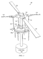
FIGURE 1 shows an examplehelicopter rotor assembly 100; -
FIGURE 2 shows a rotor system according to one example embodiment; -
FIGURE 3 shows a longitudinal cross-section of the rotor system ofFIGURE 2 ; -
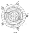
FIGURE 4 shows a transverse cross-section of the rotor system ofFIGURE 2 ; -
FIGURE 5 shows a close view of the transverse cross-section ofFIGURE 4 ; and -
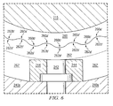
FIGURE 6 shows another close view of the transverse cross-section ofFIGURE 4 according to an alternative embodiment. -
FIGURE 1 shows an examplehelicopter rotor assembly 100.Helicopter rotor assembly 100 represents a simplified version of the helicopter rotor assembly ofFIGURE 2 . - In
FIGURE 1 ,helicopter rotor assembly 100 includes apower train 105, adrive shaft 110, arotor hub assembly 120,blades 130, aswashplate 140, andpitch links 150. In some examples,helicopter rotor assembly 100 may include more or fewer components. For example,FIGURE 1 does not show components such as a gearbox, a yoke, drive links, drive levers, and other components, such as those illustrated in the rotor assembly ofFIGURE 2 , that may be incorporated. -
Power train 105,drive shaft 110, androtor hub assembly 120 are mechanical components for transmitting torque and/or rotation.Power train 105 may include a variety of components, including an engine, a transmission, and differentials. In operation,drive shaft 110 receives torque or rotational energy frompower train 105 and rotatesrotor hub assembly 120. Rotation ofrotor hub assembly 120 causesblades 130 to rotate aboutdrive shaft 110. - Swashplate 140 translates helicopter flight control input into motion of
blades 130. Becauseblades 130 are typically spinning when the helicopter is in flight,swashplate 140 may transmit flight control input from the non-rotating fuselage to the rotatingdrive assembly 120 and/orblades 130. - In some examples,
swashplate 140 may include anon-rotating swashplate ring 140a and a rotatingswashplate ring 140b. Non-rotatingswashplate ring 140a does not rotate withdrive shaft 110, whereas rotatingswashplate ring 140b does rotate withdrive shaft 110. In the example ofFIGURE 1 ,pitch links 150 connect rotatingswashplate ring 140b toblades 130. - In operation, according to one example embodiment, translating the
non-rotating swashplate ring 140a along the axis ofdrive shaft 110 causes thepitch links 130 to move up or down. This changes the pitch angle of all blades equally, increasing or decreasing the thrust of the rotor and causing the aircraft to ascend or descend. Tilting thenon-rotating swashplate ring 140a causes the rotatingswashplate 140b to tilt, moving the pitch links up and down cyclically as they rotate with the drive shaft. This tilts the thrust vector of the rotor, causing the aircraft to translate horizontally following the direction the swashplate is tilted. - In the example of
FIGURE 1 , non-rotatingswashplate ring 140a should not rotate withdrive shaft 110, whereas rotatingswashplate ring 140b should rotate withdrive shaft 110. Teachings of certain embodiments provide the capability to prevent a non-rotating swashplate ring from rotating while allowing the rotating swashplate ring to rotate with the rotor blades. A particular embodiment is described below with regard toFIGURES 2 through 6 . -
FIGURE 2 shows arotor system 200 according to one example embodiment.Rotor system 200 features adrive shaft 210, agearbox 215, ayoke 220,grips 225,blades 230, aswashplate 240 having anon-rotating swashplate ring 240a and a rotatingswashplate ring 240b,pitch links 250,drive levers 252,drive links 254, and asleeve 260. Additional details ofrotor system 200 are described in greater detail with regard toFIGURES 3-6 . -
Drive shaft 210,yoke 220,grips 225,drive levers 252, anddrive links 254 are mechanical components for transmitting torque and/or rotation. Inrotor system 200,grips 225couple blades 230 toyoke 220, which is coupled to driveshaft 210. Drive levers 252 and drivelinks 254couple yoke 220 to rotatingswashplate ring 240b. In operation,drive shaft 210 receives torque or rotational energy and rotatesyoke 220. Rotation ofyoke 220 causesgrips 225 to rotateblades 230 and causesdrive levers 252 and drivelinks 254 to rotate rotatingswashplate ring 240b. - Swashplate 240 translates flight control input into motion of
blades 230. Becauseblades 230 are typically spinning when the helicopter is in flight,swashplate 240 may transmit flight control input from the non-rotating fuselage to the rotatingyoke 220,grips 225, and/orblades 230. - Swashplate 240 includes a
non-rotating swashplate ring 240a and a rotatingswashplate ring 240b. Non-rotatingswashplate ring 240a and rotatingswashplate ring 240b are shown in greater detail with regard toFIGURES 3-6 . Non-rotatingswashplate ring 240a does not rotate withdrive shaft 210, whereas rotatingswashplate ring 240b does rotate withdrive shaft 210. Rotatingswashplate ring 240b may be coupled toblades 230 viapitch links 250, which allow rotatingswashplate ring 240b to control deflection ofblades 230. In operation, translating or tilting non-rotating swashplate ring 240a causes rotatingswashplate ring 240b to translate or tilt, which in turn moves pitchlinks 250 up and down. -
Sleeve 260 is coupled to and aroundgearbox 215. In the illustrated embodiment,sleeve 260 is substantially cylindrical.Gearbox 215 surroundsdrive shaft 210 and separatesrotating drive shaft 210 from non-rotating components such assleeve 260 and non-rotating swashplate ring 240a. -
Sleeve 260 prevents non-rotating swashplate ring 240a from rotating withdrive shaft 210. In some embodiments, usingsleeve 260 to prevent rotating of non-rotating swashplate ring 240a may allow for ashorter rotor system 200. For example, in some embodiments,sleeve 260 may eliminate the need to externally couple non-rotating swashplate ring 240a directly togearbox 215. If non-rotating swashplate ring 240a is not coupled directly togearbox 215, then the overall size and height ofrotor system 200 may be reduced. -
FIGURE 3 shows a longitudinal cross-section of therotor system 200 ofFIGURE 2 . As shown inFIGURE 3 ,mating element 262 surrounds and mates tosleeve 260. In operation,sleeve 260 prevents rotation ofmating element 262 aboutgearbox 215.Sleeve 260 may also allowmating element 262 to move longitudinally up and downsleeve 260. The mating ofsleeve 260 tomating element 262 is described in greater detail with regard toFIGURES 4 and5 . - Non-rotating swashplate ring 240a is positioned around
mating element 262. In the example ofFIGURE 3 ,pin 242 and key 244 prevent non-rotating swashplate ring 240a from rotating about the longitudinal axis ofmating element 262 while allowing it to tilt about an axis transverse to the longitudinal axis of the mating element. In this example, key 244 fits within an opening inmating element 262.Key 244 is configured to receivepin 242. Non-rotating swashplate ring 240a also includes openings configured to receivepin 242 such thatpin 242 preventsmating element 262 and non-rotating swashplate ring 240a from rotating relative to one another relative to the longitudinal axis.Pin 242 and key 244 are shown in greater detail inFIGURES 4 and5 . -
Mating element 262 may include a curved outer surface. This curved outer surface, also known as a "tilt ball," allowsswashplate 240 to tilt up and down. As stated above, tilting non-rotating swashplate ring 240a causes rotatingswashplate ring 240b to tilt, which in turn moves pitchlinks 250 up and down and deflectsblades 230. Thus, teachings of certain embodiments recognize the capability to prevent rotation of non-rotating swashplate ring 240a while allowing tilting of non-rotating swashplate ring 240a relative to the tilt ball ofmating element 262. - Bearing 246 separates
mating element 262 and non-rotating swashplate ring 240a. In some embodiments, bearing 246 may prevent non-rotating swashplate ring 240a from wearing againstmating element 262. Bearing 246 may be made of any suitable bearing material, such as Teflon. - Rotating
swashplate ring 240b is positioned around non-rotating swashplate ring 240a. Bearing 248 separates rotatingswashplate ring 240b from non-rotating swashplate ring 240a to prevent wearing and to reduce friction when rotatingswashplate ring 240b rotates relative to non-rotating swashplate ring 240a. In operation, rotatingswashplate ring 240b rotates withdrive levers 252 and drivelinks 254. Rotatingswashplate ring 240b also tilts up and down with non-rotating swashplate ring 240a as non-rotating swashplate ring 240a tilts up and down the curved surface ofmating element 262. -
FIGURE 4 shows a transverse cross-section of therotor system 200 ofFIGURE 2 . As shown inFIGURE 4 ,gearbox 215 surroundsdrive shaft 210.Sleeve 260 is coupled to and aroundgearbox 215.Mating element 262 mates tosleeve 260 such thatsleeve 260 prevents rotation ofmating element 262 aboutgearbox 215. Non-rotating swashplate ring 240a is positioned aroundmating element 262.Pin 242 and key 244 prevent non-rotating swashplate ring 240a from rotating aroundgearbox 215. Rotatingswashplate ring 240b is positioned around non-rotating swashplate ring 240a and is free to rotate alongbearings 248. - As shown in
FIGURE 4 ,sleeve 260 includes grooves and ridges that mate with ridges and grooves ofmating element 262. In the example ofFIGURE 4 , the grooves and ridges ofsleeve 260 alternate continuously about the full outer diameter ofsleeve 260, and the grooves and ridges ofmating element 262 alternate continuously about the full inner diameter ofmating element 262. The ridges and grooves ofsleeve 260 andmating element 262 are shown in greater detail in -
FIGURE 5 . - In some embodiments, ridges and grooves of
sleeve 260 andmating element 262 interlock so as to eliminate open spaces betweensleeve 260 andmating element 262. Eliminating open spaces may allow the outer diameter ofmating element 262 to be reduced. In turn, reducing the outer diameter ofmating element 262 may allow the diameters of non-rotating swashplate ring 242a and rotating swashplate ring 242b to be reduced. Accordingly, teachings of certain embodiments recognize that using mating ridges and grooves may reduce the outer diameter ofswashplate 240. -
FIGURE 5 shows a close view of the transverse cross-section ofFIGURE 4 . As shown inFIGURE 5 ,sleeve 260 featuresgrooves 260a andridges 260b, andmating element 262 featuresgrooves 262a andridges 262b. In this example,grooves 260a mate withridges 262b, andridges 260b mate withgrooves 262a. - In some embodiments, the mating surfaces of
sleeve 260 and/ormating element 262 may be treated with a bearing coating to reduce wear and friction between the parts. For example,sleeve 260 and/ormating element 262 may be anodized. Anodization is an electrolytic passivation process used to increase the thickness of the natural oxide layer on the surface of metal parts. In one example embodiment,sleeve 260 and/ormating element 262 may be treated using a process called Keronite, which may produce a hard, dense ceramic surface layer onsleeve 260 and/ormating element 262. - In the example of
FIGURE 5 ,ridges grooves Ridges grooves FIGURE 6 shows a sleeve 260' havinggrooves 260a' andridges 260b' and a mating element 262' havinggrooves 262a' andridges 262b'. Unlike the ridges and grooves ofFIGURE 5 ,ridges 260b' and 262b' have curved peaks, andgrooves 260a' and 262a' have curved valleys. In the example ofFIGURE 6 ,grooves 260a' mate withridges 262b' andgrooves 262a' mate withridges 260b' so as to prevent mating element 262' from rotating about sleeve 260'. - Modifications, additions, or omissions may be made to the systems and apparatuses described herein without departing from the scope of the invention. The components of the systems and apparatuses may be integrated or separated. Moreover, the operations of the systems and apparatuses may be performed by more, fewer, or other components. The methods may include more, fewer, or other steps. Additionally, steps may be performed in any suitable order.
- Although several embodiments have been illustrated and described in detail, it will be recognized that substitutions and alterations are possible without departing from the spirit and scope of the present invention, as defined by the appended claims.
Claims (12)
- A rotor system, comprising:a mating element having a first plurality of grooves a first plurality of ridges;a sleeve positioned inside the mating element such that the sleeve prevents rotation of the mating element about the sleeve, the sleeve having a second plurality of grooves mating with the first plurality of ridges and a second plurality of ridges mating with the first plurality of grooves;a first swashplate ring positioned around the mating element;a locking element preventing the first swashplate ring from rotating about the axis of the sleeve; anda second swashplate ring rotatable about the sleeve.
- A rotor system, comprising:a gearbox;a mating element having a first plurality of grooves a first plurality of ridges;a sleeve coupled to and around the gear box and positioned inside the mating element such that the sleeve prevents rotation of the mating element about the sleeve, the sleeve having a second plurality of grooves mating with the first plurality of ridges and a second plurality of ridges mating with the first plurality of grooves.
- A helicopter, comprising:a power train operable to rotate a drive shaft;a plurality of rotor blades operable to rotate in response to rotation of the drive shaft;a gearbox surrounding a portion of the drive shaft;a mating element having a first plurality of grooves a first plurality of ridges;a sleeve positioned inside the mating element such that the sleeve prevents rotation of the mating element about the sleeve, the sleeve having a second plurality of grooves mating with the first plurality of ridges and a second plurality of ridges mating with the first plurality of grooves;a first swashplate ring positioned around the mating element;a locking element preventing the first swashplate ring from rotating about the sleeve; anda second swashplate ring rotatable about the sleeve with rotation of the plurality of rotor blades.
- The rotor system of claim 1, further comprising a gearbox, wherein the sleeve is coupled to and around the gearbox.
- The rotor system of claim 1 or of claim 2 of or claim 4, or the helicopter of claim 3, wherein the second plurality of grooves and the second plurality of ridges alternate continuously about the sleeve.
- The rotor system of claim 1 or of claim 2 or of claim 4 or claim 5, or the helicopter of claim 3 or of claim 5, wherein:the mating element comprises a curved surface; andthe first swashplate ring is pivotable along the curved surface.
- The rotor system of claim 1 or of claim 2 or of any of claims 4 to 6, or the helicopter of claim 3 or of claim 5 or claim 6, further comprising a key element positioned in an opening of the mating element and configured to receive the locking device.
- The rotor system of claim 1 or of claim 2 or of any of claims 4 to 7, or the helicopter of claim 3 or of any of claims 5 to 7, wherein the plurality of first ridges comprises at least five ridges.
- The rotor system of claim 1 or of claim 2, or of any of claims 4 to 8, or the helicopter of claim 3 or of any of claims 5 to 8, wherein the mating element is configured to slide axially relative to the sleeve.
- The rotor system of claim 2, further comprising:a first swashplate ring positioned around the mating element;a locking element preventing the first swashplate ring from rotating about the sleeve; anda second swashplate ring rotatable about the sleeve with rotation of the plurality of rotor blades.
- The rotor system of claim 10, wherein:the mating element comprises a curved surface; andthe first swashplate ring is pivotable along the curved surface.
- The rotor system of claim 10, further comprising a key element positioned in an opening of the mating element and configured to receive the locking device.
Priority Applications (1)
| Application Number | Priority Date | Filing Date | Title |
|---|---|---|---|
| CA2798339A CA2798339C (en) | 2011-12-09 | 2012-12-07 | Preventing rotation of a fixed ring of a swashplate |
Applications Claiming Priority (1)
| Application Number | Priority Date | Filing Date | Title |
|---|---|---|---|
| US13/316,061 US8961138B2 (en) | 2011-12-09 | 2011-12-09 | Preventing rotation of a fixed ring of a swashplate |
Publications (2)
| Publication Number | Publication Date |
|---|---|
| EP2602186A1 true EP2602186A1 (en) | 2013-06-12 |
| EP2602186B1 EP2602186B1 (en) | 2015-09-30 |
Family
ID=45476424
Family Applications (1)
| Application Number | Title | Priority Date | Filing Date |
|---|---|---|---|
| EP12150685.1A Active EP2602186B1 (en) | 2011-12-09 | 2012-01-10 | Preventing rotation of a fixed ring of a swashplate |
Country Status (3)
| Country | Link |
|---|---|
| US (1) | US8961138B2 (en) |
| EP (1) | EP2602186B1 (en) |
| CA (1) | CA2798339C (en) |
Families Citing this family (7)
| Publication number | Priority date | Publication date | Assignee | Title |
|---|---|---|---|---|
| US10464666B2 (en) * | 2014-11-20 | 2019-11-05 | Sikorsky Aircraft Corporation | Composite reinforced swashplate |
| US10618646B2 (en) * | 2017-05-26 | 2020-04-14 | Textron Innovations Inc. | Rotor assembly having a ball joint for thrust vectoring capabilities |
| US10994840B1 (en) | 2017-08-16 | 2021-05-04 | United States Of America As Represented By The Secretary Of The Air Force | Thrust vectoring control of a cyclorotor |
| US10836479B2 (en) * | 2018-06-19 | 2020-11-17 | Bell Textron Inc. | Rotating swashplate ring to rotor mast connection |
| US11643197B2 (en) | 2018-12-05 | 2023-05-09 | Textron Innovations Inc. | Reduced height swashplate assembly |
| US11440653B2 (en) * | 2020-06-05 | 2022-09-13 | Textron Innovations Inc. | Anti-drive mechanism for rotary aircraft control |
| US11780574B2 (en) | 2021-06-03 | 2023-10-10 | Lockheed Martin Corporation | Swashplate assembly for a rotor system |
Citations (4)
| Publication number | Priority date | Publication date | Assignee | Title |
|---|---|---|---|---|
| GB2043010A (en) * | 1979-02-27 | 1980-10-01 | Agusta Aeronaut Costr | Helicopter rotor shaft with internal pitch control linkages |
| US5599167A (en) * | 1994-10-13 | 1997-02-04 | Eurocopter France | Device for controlling the pitch of the blades of a rotorcraft rotor |
| DE19613462A1 (en) * | 1996-04-04 | 1997-10-16 | Hubert Taubert | Shaft and boss joint between screw and screwdriver head |
| EP2314507A1 (en) * | 2009-10-23 | 2011-04-27 | Eurocopter | Pitch control swash plate assembly of a main rotor as well as a rotor with such an assembly |
Family Cites Families (13)
| Publication number | Priority date | Publication date | Assignee | Title |
|---|---|---|---|---|
| US2973815A (en) * | 1957-11-08 | 1961-03-07 | Omega Aircraft Corp | Pitch control mechanism for helicopter rotors |
| US3841586A (en) * | 1973-04-26 | 1974-10-15 | Boeing Co | Rotor swashplate assembly |
| US4930988A (en) | 1989-01-02 | 1990-06-05 | Honeywell Inc | Individual blade control system for helicopters |
| FR2661886B1 (en) * | 1990-05-14 | 1992-08-28 | Aerospatiale | DEVICE WITH CYCLIC PLATES MOUNTED ON JOINTS DECOUPLED INTO TANGING AND ROLLING, FOR CONTROLLING THE PITCH OF THE BLADES OF A GIRAVION ROTOR. |
| US5135356A (en) | 1990-09-28 | 1992-08-04 | The Boeing Company | Swashplate anti-drive linkage for rotor controls of rotary wing aircraft |
| US5083725A (en) | 1990-10-11 | 1992-01-28 | United Technologies Corporation | Elastomeric swashplate configuration for helicopters |
| US5351913A (en) | 1992-06-22 | 1994-10-04 | United Technologies Corporation | Coaxial transmission/center hub subassembly for a rotor assembly having ducted, coaxial counter-rotating rotors |
| US5785497A (en) | 1997-03-11 | 1998-07-28 | Sikorsky Aircraft Corporation | Control rod mounting arrangement for helicopter swashplates |
| FR2770828B1 (en) * | 1997-11-13 | 2000-01-14 | Eurocopter France | DEVICE WITH CYCLICAL PLATES FOR CONTROLLING THE PITCH OF THE BLADES OF A ROTOR WITH A NON-ROTATING PLATE ARTICULATED ON A CENTRAL BALL JOINT |
| IT1308395B1 (en) | 1999-02-26 | 2001-12-17 | Finmeccanica Spa | CYCLIC AND COLLECTIVE STEP CONTROL DEVICE FOR A ROTOR OF A HELICOPTER. |
| FR2848524B1 (en) * | 2002-12-13 | 2005-12-09 | Eurocopter France | CYCLIC TRAY DEVICE FOR CONTROLLING THE PITCH OF THE BLADES OF A ROTOR OF GIRAVION |
| CN101107163A (en) * | 2005-11-30 | 2008-01-16 | 贝尔直升机泰克斯特龙公司 | rotorcraft torque converter |
| FR2946620A1 (en) * | 2009-06-16 | 2010-12-17 | Eurocopter France | METHOD FOR ASSISTING STEERING AID, MEANS FOR STEERING AID AND DEVICE FOR ASSISTING ROTOR DRIVING USING SAID STEERING AID MEANS FOR CARRYING OUT SAID STEERING AID METHOD. |
-
2011
- 2011-12-09 US US13/316,061 patent/US8961138B2/en active Active
-
2012
- 2012-01-10 EP EP12150685.1A patent/EP2602186B1/en active Active
- 2012-12-07 CA CA2798339A patent/CA2798339C/en active Active
Patent Citations (4)
| Publication number | Priority date | Publication date | Assignee | Title |
|---|---|---|---|---|
| GB2043010A (en) * | 1979-02-27 | 1980-10-01 | Agusta Aeronaut Costr | Helicopter rotor shaft with internal pitch control linkages |
| US5599167A (en) * | 1994-10-13 | 1997-02-04 | Eurocopter France | Device for controlling the pitch of the blades of a rotorcraft rotor |
| DE19613462A1 (en) * | 1996-04-04 | 1997-10-16 | Hubert Taubert | Shaft and boss joint between screw and screwdriver head |
| EP2314507A1 (en) * | 2009-10-23 | 2011-04-27 | Eurocopter | Pitch control swash plate assembly of a main rotor as well as a rotor with such an assembly |
Also Published As
| Publication number | Publication date |
|---|---|
| EP2602186B1 (en) | 2015-09-30 |
| US20130149150A1 (en) | 2013-06-13 |
| CA2798339C (en) | 2015-10-20 |
| CA2798339A1 (en) | 2013-06-09 |
| US8961138B2 (en) | 2015-02-24 |
Similar Documents
| Publication | Publication Date | Title |
|---|---|---|
| CA2798339C (en) | Preventing rotation of a fixed ring of a swashplate | |
| EP2730505B1 (en) | Preventing rotation of a fixed ring of a swashplate | |
| US9010679B2 (en) | Hybrid spherical and thrust bearing | |
| US9254915B2 (en) | Rotor system with torque-splitter assembly | |
| EP2610168B1 (en) | Adjustable pitch link | |
| EP2778062A1 (en) | Gimbaled tail rotor hub with spherical elastomeric centrifugal force bearing for blade retention and pitch change articulation | |
| US10836479B2 (en) | Rotating swashplate ring to rotor mast connection | |
| EP2274203A1 (en) | Rotor hub systems and methods | |
| US11891168B2 (en) | Bearingless gimbaled rotor hubs and swashplates | |
| US11493121B2 (en) | Gear systems having bearing flexure mounted thrust bearings | |
| US9840325B2 (en) | Dual series pitch link bearing | |
| CN103770940A (en) | System and method for providing collective control in an aircraft | |
| US9347487B2 (en) | Rotorcraft bearing with rotation slip joint | |
| EP3919380B1 (en) | Anti-drive mechanism for rotary aircraft control | |
| US10960972B2 (en) | Rotorcraft masts having a nonintegral raceway | |
| KR20220038299A (en) | Anti-torque rotors for helicopters | |
| EP2799730A1 (en) | Hybrid sliding element and elastomeric bearing | |
| US10696386B2 (en) | Rigid rotor head with tension torsion (TT) strap retention | |
| EP3663198B1 (en) | Reduced height swashplate assembly | |
| RU176027U1 (en) | HELICOPTER WITH COLLECTIVE BACKGROUND SCREWS |
Legal Events
| Date | Code | Title | Description |
|---|---|---|---|
| PUAI | Public reference made under article 153(3) epc to a published international application that has entered the european phase |
Free format text: ORIGINAL CODE: 0009012 |
|
| 17P | Request for examination filed |
Effective date: 20120110 |
|
| AK | Designated contracting states |
Kind code of ref document: A1 Designated state(s): AL AT BE BG CH CY CZ DE DK EE ES FI FR GB GR HR HU IE IS IT LI LT LU LV MC MK MT NL NO PL PT RO RS SE SI SK SM TR |
|
| AX | Request for extension of the european patent |
Extension state: BA ME |
|
| 17Q | First examination report despatched |
Effective date: 20140917 |
|
| GRAP | Despatch of communication of intention to grant a patent |
Free format text: ORIGINAL CODE: EPIDOSNIGR1 |
|
| INTG | Intention to grant announced |
Effective date: 20150409 |
|
| GRAP | Despatch of communication of intention to grant a patent |
Free format text: ORIGINAL CODE: EPIDOSNIGR1 |
|
| GRAS | Grant fee paid |
Free format text: ORIGINAL CODE: EPIDOSNIGR3 |
|
| INTG | Intention to grant announced |
Effective date: 20150728 |
|
| GRAA | (expected) grant |
Free format text: ORIGINAL CODE: 0009210 |
|
| AK | Designated contracting states |
Kind code of ref document: B1 Designated state(s): AL AT BE BG CH CY CZ DE DK EE ES FI FR GB GR HR HU IE IS IT LI LT LU LV MC MK MT NL NO PL PT RO RS SE SI SK SM TR |
|
| REG | Reference to a national code |
Ref country code: CH Ref legal event code: EP Ref country code: GB Ref legal event code: FG4D |
|
| REG | Reference to a national code |
Ref country code: AT Ref legal event code: REF Ref document number: 752222 Country of ref document: AT Kind code of ref document: T Effective date: 20151015 |
|
| REG | Reference to a national code |
Ref country code: IE Ref legal event code: FG4D |
|
| REG | Reference to a national code |
Ref country code: DE Ref legal event code: R096 Ref document number: 602012011043 Country of ref document: DE |
|
| REG | Reference to a national code |
Ref country code: FR Ref legal event code: PLFP Year of fee payment: 5 |
|
| PG25 | Lapsed in a contracting state [announced via postgrant information from national office to epo] |
Ref country code: FI Free format text: LAPSE BECAUSE OF FAILURE TO SUBMIT A TRANSLATION OF THE DESCRIPTION OR TO PAY THE FEE WITHIN THE PRESCRIBED TIME-LIMIT Effective date: 20150930 Ref country code: LT Free format text: LAPSE BECAUSE OF FAILURE TO SUBMIT A TRANSLATION OF THE DESCRIPTION OR TO PAY THE FEE WITHIN THE PRESCRIBED TIME-LIMIT Effective date: 20150930 Ref country code: LV Free format text: LAPSE BECAUSE OF FAILURE TO SUBMIT A TRANSLATION OF THE DESCRIPTION OR TO PAY THE FEE WITHIN THE PRESCRIBED TIME-LIMIT Effective date: 20150930 Ref country code: NO Free format text: LAPSE BECAUSE OF FAILURE TO SUBMIT A TRANSLATION OF THE DESCRIPTION OR TO PAY THE FEE WITHIN THE PRESCRIBED TIME-LIMIT Effective date: 20151230 Ref country code: GR Free format text: LAPSE BECAUSE OF FAILURE TO SUBMIT A TRANSLATION OF THE DESCRIPTION OR TO PAY THE FEE WITHIN THE PRESCRIBED TIME-LIMIT Effective date: 20151231 |
|
| REG | Reference to a national code |
Ref country code: NL Ref legal event code: MP Effective date: 20150930 |
|
| REG | Reference to a national code |
Ref country code: LT Ref legal event code: MG4D |
|
| REG | Reference to a national code |
Ref country code: AT Ref legal event code: MK05 Ref document number: 752222 Country of ref document: AT Kind code of ref document: T Effective date: 20150930 |
|
| PG25 | Lapsed in a contracting state [announced via postgrant information from national office to epo] |
Ref country code: RS Free format text: LAPSE BECAUSE OF FAILURE TO SUBMIT A TRANSLATION OF THE DESCRIPTION OR TO PAY THE FEE WITHIN THE PRESCRIBED TIME-LIMIT Effective date: 20150930 Ref country code: HR Free format text: LAPSE BECAUSE OF FAILURE TO SUBMIT A TRANSLATION OF THE DESCRIPTION OR TO PAY THE FEE WITHIN THE PRESCRIBED TIME-LIMIT Effective date: 20150930 Ref country code: SE Free format text: LAPSE BECAUSE OF FAILURE TO SUBMIT A TRANSLATION OF THE DESCRIPTION OR TO PAY THE FEE WITHIN THE PRESCRIBED TIME-LIMIT Effective date: 20150930 |
|
| PG25 | Lapsed in a contracting state [announced via postgrant information from national office to epo] |
Ref country code: CZ Free format text: LAPSE BECAUSE OF FAILURE TO SUBMIT A TRANSLATION OF THE DESCRIPTION OR TO PAY THE FEE WITHIN THE PRESCRIBED TIME-LIMIT Effective date: 20150930 Ref country code: IS Free format text: LAPSE BECAUSE OF FAILURE TO SUBMIT A TRANSLATION OF THE DESCRIPTION OR TO PAY THE FEE WITHIN THE PRESCRIBED TIME-LIMIT Effective date: 20160130 Ref country code: EE Free format text: LAPSE BECAUSE OF FAILURE TO SUBMIT A TRANSLATION OF THE DESCRIPTION OR TO PAY THE FEE WITHIN THE PRESCRIBED TIME-LIMIT Effective date: 20150930 Ref country code: SK Free format text: LAPSE BECAUSE OF FAILURE TO SUBMIT A TRANSLATION OF THE DESCRIPTION OR TO PAY THE FEE WITHIN THE PRESCRIBED TIME-LIMIT Effective date: 20150930 Ref country code: NL Free format text: LAPSE BECAUSE OF FAILURE TO SUBMIT A TRANSLATION OF THE DESCRIPTION OR TO PAY THE FEE WITHIN THE PRESCRIBED TIME-LIMIT Effective date: 20150930 Ref country code: ES Free format text: LAPSE BECAUSE OF FAILURE TO SUBMIT A TRANSLATION OF THE DESCRIPTION OR TO PAY THE FEE WITHIN THE PRESCRIBED TIME-LIMIT Effective date: 20150930 |
|
| PG25 | Lapsed in a contracting state [announced via postgrant information from national office to epo] |
Ref country code: BE Free format text: LAPSE BECAUSE OF NON-PAYMENT OF DUE FEES Effective date: 20160131 Ref country code: AT Free format text: LAPSE BECAUSE OF FAILURE TO SUBMIT A TRANSLATION OF THE DESCRIPTION OR TO PAY THE FEE WITHIN THE PRESCRIBED TIME-LIMIT Effective date: 20150930 Ref country code: RO Free format text: LAPSE BECAUSE OF FAILURE TO SUBMIT A TRANSLATION OF THE DESCRIPTION OR TO PAY THE FEE WITHIN THE PRESCRIBED TIME-LIMIT Effective date: 20150930 Ref country code: PT Free format text: LAPSE BECAUSE OF FAILURE TO SUBMIT A TRANSLATION OF THE DESCRIPTION OR TO PAY THE FEE WITHIN THE PRESCRIBED TIME-LIMIT Effective date: 20160201 Ref country code: PL Free format text: LAPSE BECAUSE OF FAILURE TO SUBMIT A TRANSLATION OF THE DESCRIPTION OR TO PAY THE FEE WITHIN THE PRESCRIBED TIME-LIMIT Effective date: 20150930 |
|
| REG | Reference to a national code |
Ref country code: DE Ref legal event code: R097 Ref document number: 602012011043 Country of ref document: DE |
|
| PLBE | No opposition filed within time limit |
Free format text: ORIGINAL CODE: 0009261 |
|
| STAA | Information on the status of an ep patent application or granted ep patent |
Free format text: STATUS: NO OPPOSITION FILED WITHIN TIME LIMIT |
|
| PG25 | Lapsed in a contracting state [announced via postgrant information from national office to epo] |
Ref country code: LU Free format text: LAPSE BECAUSE OF FAILURE TO SUBMIT A TRANSLATION OF THE DESCRIPTION OR TO PAY THE FEE WITHIN THE PRESCRIBED TIME-LIMIT Effective date: 20160110 Ref country code: DK Free format text: LAPSE BECAUSE OF FAILURE TO SUBMIT A TRANSLATION OF THE DESCRIPTION OR TO PAY THE FEE WITHIN THE PRESCRIBED TIME-LIMIT Effective date: 20150930 |
|
| REG | Reference to a national code |
Ref country code: CH Ref legal event code: PL |
|
| 26N | No opposition filed |
Effective date: 20160701 |
|
| PG25 | Lapsed in a contracting state [announced via postgrant information from national office to epo] |
Ref country code: MC Free format text: LAPSE BECAUSE OF FAILURE TO SUBMIT A TRANSLATION OF THE DESCRIPTION OR TO PAY THE FEE WITHIN THE PRESCRIBED TIME-LIMIT Effective date: 20150930 |
|
| PG25 | Lapsed in a contracting state [announced via postgrant information from national office to epo] |
Ref country code: LI Free format text: LAPSE BECAUSE OF NON-PAYMENT OF DUE FEES Effective date: 20160131 Ref country code: CH Free format text: LAPSE BECAUSE OF NON-PAYMENT OF DUE FEES Effective date: 20160131 |
|
| REG | Reference to a national code |
Ref country code: IE Ref legal event code: MM4A |
|
| PG25 | Lapsed in a contracting state [announced via postgrant information from national office to epo] |
Ref country code: SI Free format text: LAPSE BECAUSE OF FAILURE TO SUBMIT A TRANSLATION OF THE DESCRIPTION OR TO PAY THE FEE WITHIN THE PRESCRIBED TIME-LIMIT Effective date: 20150930 |
|
| PG25 | Lapsed in a contracting state [announced via postgrant information from national office to epo] |
Ref country code: BE Free format text: LAPSE BECAUSE OF FAILURE TO SUBMIT A TRANSLATION OF THE DESCRIPTION OR TO PAY THE FEE WITHIN THE PRESCRIBED TIME-LIMIT Effective date: 20150930 |
|
| REG | Reference to a national code |
Ref country code: FR Ref legal event code: PLFP Year of fee payment: 6 |
|
| PG25 | Lapsed in a contracting state [announced via postgrant information from national office to epo] |
Ref country code: IE Free format text: LAPSE BECAUSE OF NON-PAYMENT OF DUE FEES Effective date: 20160110 |
|
| PG25 | Lapsed in a contracting state [announced via postgrant information from national office to epo] |
Ref country code: MT Free format text: LAPSE BECAUSE OF FAILURE TO SUBMIT A TRANSLATION OF THE DESCRIPTION OR TO PAY THE FEE WITHIN THE PRESCRIBED TIME-LIMIT Effective date: 20150930 |
|
| REG | Reference to a national code |
Ref country code: FR Ref legal event code: PLFP Year of fee payment: 7 |
|
| PG25 | Lapsed in a contracting state [announced via postgrant information from national office to epo] |
Ref country code: HU Free format text: LAPSE BECAUSE OF FAILURE TO SUBMIT A TRANSLATION OF THE DESCRIPTION OR TO PAY THE FEE WITHIN THE PRESCRIBED TIME-LIMIT; INVALID AB INITIO Effective date: 20120110 Ref country code: SM Free format text: LAPSE BECAUSE OF FAILURE TO SUBMIT A TRANSLATION OF THE DESCRIPTION OR TO PAY THE FEE WITHIN THE PRESCRIBED TIME-LIMIT Effective date: 20150930 Ref country code: CY Free format text: LAPSE BECAUSE OF FAILURE TO SUBMIT A TRANSLATION OF THE DESCRIPTION OR TO PAY THE FEE WITHIN THE PRESCRIBED TIME-LIMIT Effective date: 20150930 |
|
| PG25 | Lapsed in a contracting state [announced via postgrant information from national office to epo] |
Ref country code: MT Free format text: LAPSE BECAUSE OF FAILURE TO SUBMIT A TRANSLATION OF THE DESCRIPTION OR TO PAY THE FEE WITHIN THE PRESCRIBED TIME-LIMIT Effective date: 20160131 Ref country code: TR Free format text: LAPSE BECAUSE OF FAILURE TO SUBMIT A TRANSLATION OF THE DESCRIPTION OR TO PAY THE FEE WITHIN THE PRESCRIBED TIME-LIMIT Effective date: 20150930 Ref country code: MK Free format text: LAPSE BECAUSE OF FAILURE TO SUBMIT A TRANSLATION OF THE DESCRIPTION OR TO PAY THE FEE WITHIN THE PRESCRIBED TIME-LIMIT Effective date: 20150930 |
|
| PG25 | Lapsed in a contracting state [announced via postgrant information from national office to epo] |
Ref country code: BG Free format text: LAPSE BECAUSE OF FAILURE TO SUBMIT A TRANSLATION OF THE DESCRIPTION OR TO PAY THE FEE WITHIN THE PRESCRIBED TIME-LIMIT Effective date: 20150930 |
|
| PG25 | Lapsed in a contracting state [announced via postgrant information from national office to epo] |
Ref country code: AL Free format text: LAPSE BECAUSE OF FAILURE TO SUBMIT A TRANSLATION OF THE DESCRIPTION OR TO PAY THE FEE WITHIN THE PRESCRIBED TIME-LIMIT Effective date: 20150930 |
|
| P01 | Opt-out of the competence of the unified patent court (upc) registered |
Effective date: 20230602 |
|
| PGFP | Annual fee paid to national office [announced via postgrant information from national office to epo] |
Ref country code: GB Payment date: 20260127 Year of fee payment: 15 |
|
| PGFP | Annual fee paid to national office [announced via postgrant information from national office to epo] |
Ref country code: DE Payment date: 20260128 Year of fee payment: 15 |
|
| PGFP | Annual fee paid to national office [announced via postgrant information from national office to epo] |
Ref country code: IT Payment date: 20260121 Year of fee payment: 15 |
|
| PGFP | Annual fee paid to national office [announced via postgrant information from national office to epo] |
Ref country code: FR Payment date: 20260126 Year of fee payment: 15 |