EP2601720B1 - Reactive power regulation of a windpark - Google Patents
Reactive power regulation of a windpark Download PDFInfo
- Publication number
- EP2601720B1 EP2601720B1 EP10737586.7A EP10737586A EP2601720B1 EP 2601720 B1 EP2601720 B1 EP 2601720B1 EP 10737586 A EP10737586 A EP 10737586A EP 2601720 B1 EP2601720 B1 EP 2601720B1
- Authority
- EP
- European Patent Office
- Prior art keywords
- local
- reactive power
- control mode
- central
- control system
- Prior art date
- Legal status (The legal status is an assumption and is not a legal conclusion. Google has not performed a legal analysis and makes no representation as to the accuracy of the status listed.)
- Active
Links
Images



Classifications
-
- H—ELECTRICITY
- H02—GENERATION; CONVERSION OR DISTRIBUTION OF ELECTRIC POWER
- H02J—ELECTRIC POWER NETWORKS; CIRCUIT ARRANGEMENTS OR SYSTEMS FOR SUPPLYING OR DISTRIBUTING ELECTRIC POWER; SYSTEMS FOR STORING ELECTRIC ENERGY
- H02J3/00—Circuit arrangements for AC mains or AC distribution networks
- H02J3/18—Arrangements for adjusting, eliminating or compensating reactive power in networks
- H02J3/1821—Arrangements for adjusting, eliminating or compensating reactive power in networks using shunt compensators
- H02J3/1835—Arrangements for adjusting, eliminating or compensating reactive power in networks using shunt compensators with stepless control
- H02J3/1842—Arrangements for adjusting, eliminating or compensating reactive power in networks using shunt compensators with stepless control having reactive elements actively controlled by bridge converters, e.g. active filters or static compensators [STATCOM]
-
- F—MECHANICAL ENGINEERING; LIGHTING; HEATING; WEAPONS; BLASTING
- F03—MACHINES OR ENGINES FOR LIQUIDS; WIND, SPRING, OR WEIGHT MOTORS; PRODUCING MECHANICAL POWER OR A REACTIVE PROPULSIVE THRUST, NOT OTHERWISE PROVIDED FOR
- F03D—WIND MOTORS
- F03D7/00—Controlling wind motors
-
- F—MECHANICAL ENGINEERING; LIGHTING; HEATING; WEAPONS; BLASTING
- F03—MACHINES OR ENGINES FOR LIQUIDS; WIND, SPRING, OR WEIGHT MOTORS; PRODUCING MECHANICAL POWER OR A REACTIVE PROPULSIVE THRUST, NOT OTHERWISE PROVIDED FOR
- F03D—WIND MOTORS
- F03D7/00—Controlling wind motors
- F03D7/02—Controlling wind motors the wind motors having rotation axis substantially parallel to the air flow entering the rotor
- F03D7/028—Controlling wind motors the wind motors having rotation axis substantially parallel to the air flow entering the rotor controlling wind motor output power
- F03D7/0284—Controlling wind motors the wind motors having rotation axis substantially parallel to the air flow entering the rotor controlling wind motor output power in relation to the state of the electric grid
-
- F—MECHANICAL ENGINEERING; LIGHTING; HEATING; WEAPONS; BLASTING
- F03—MACHINES OR ENGINES FOR LIQUIDS; WIND, SPRING, OR WEIGHT MOTORS; PRODUCING MECHANICAL POWER OR A REACTIVE PROPULSIVE THRUST, NOT OTHERWISE PROVIDED FOR
- F03D—WIND MOTORS
- F03D7/00—Controlling wind motors
- F03D7/02—Controlling wind motors the wind motors having rotation axis substantially parallel to the air flow entering the rotor
- F03D7/04—Automatic control; Regulation
- F03D7/042—Automatic control; Regulation by means of an electrical or electronic controller
- F03D7/048—Automatic control; Regulation by means of an electrical or electronic controller controlling wind farms
-
- F—MECHANICAL ENGINEERING; LIGHTING; HEATING; WEAPONS; BLASTING
- F03—MACHINES OR ENGINES FOR LIQUIDS; WIND, SPRING, OR WEIGHT MOTORS; PRODUCING MECHANICAL POWER OR A REACTIVE PROPULSIVE THRUST, NOT OTHERWISE PROVIDED FOR
- F03D—WIND MOTORS
- F03D9/00—Adaptations of wind motors for special use; Combinations of wind motors with apparatus driven thereby; Wind motors specially adapted for installation in particular locations
- F03D9/20—Wind motors characterised by the driven apparatus
- F03D9/25—Wind motors characterised by the driven apparatus the apparatus being an electrical generator
- F03D9/255—Wind motors characterised by the driven apparatus the apparatus being an electrical generator connected to electrical distribution networks; Arrangements therefor
- F03D9/257—Wind motors characterised by the driven apparatus the apparatus being an electrical generator connected to electrical distribution networks; Arrangements therefor the wind motor being part of a wind farm
-
- H—ELECTRICITY
- H02—GENERATION; CONVERSION OR DISTRIBUTION OF ELECTRIC POWER
- H02J—ELECTRIC POWER NETWORKS; CIRCUIT ARRANGEMENTS OR SYSTEMS FOR SUPPLYING OR DISTRIBUTING ELECTRIC POWER; SYSTEMS FOR STORING ELECTRIC ENERGY
- H02J3/00—Circuit arrangements for AC mains or AC distribution networks
- H02J3/18—Arrangements for adjusting, eliminating or compensating reactive power in networks
- H02J3/1892—Arrangements for adjusting, eliminating or compensating reactive power in networks the arrangements being an integral part of the loads or of their control circuits
-
- H—ELECTRICITY
- H02—GENERATION; CONVERSION OR DISTRIBUTION OF ELECTRIC POWER
- H02J—ELECTRIC POWER NETWORKS; CIRCUIT ARRANGEMENTS OR SYSTEMS FOR SUPPLYING OR DISTRIBUTING ELECTRIC POWER; SYSTEMS FOR STORING ELECTRIC ENERGY
- H02J3/00—Circuit arrangements for AC mains or AC distribution networks
- H02J3/38—Arrangements for feeding a single network from two or more generators or sources in parallel; Arrangements for feeding already energised networks from additional generators or sources in parallel
- H02J3/381—Dispersed generators
-
- H—ELECTRICITY
- H02—GENERATION; CONVERSION OR DISTRIBUTION OF ELECTRIC POWER
- H02J—ELECTRIC POWER NETWORKS; CIRCUIT ARRANGEMENTS OR SYSTEMS FOR SUPPLYING OR DISTRIBUTING ELECTRIC POWER; SYSTEMS FOR STORING ELECTRIC ENERGY
- H02J3/00—Circuit arrangements for AC mains or AC distribution networks
- H02J3/38—Arrangements for feeding a single network from two or more generators or sources in parallel; Arrangements for feeding already energised networks from additional generators or sources in parallel
- H02J3/46—Controlling the sharing of generated power between the generators, sources or networks
- H02J3/466—Scheduling or selectively controlling the operation of the generators or sources, e.g. connecting or disconnecting generators to meet a demand
- H02J3/472—Scheduling or selectively controlling the operation of the generators or sources, e.g. connecting or disconnecting generators to meet a demand for selectively connecting the AC sources in a particular order, e.g. sequential, alternating or subsets of sources
-
- H—ELECTRICITY
- H02—GENERATION; CONVERSION OR DISTRIBUTION OF ELECTRIC POWER
- H02J—ELECTRIC POWER NETWORKS; CIRCUIT ARRANGEMENTS OR SYSTEMS FOR SUPPLYING OR DISTRIBUTING ELECTRIC POWER; SYSTEMS FOR STORING ELECTRIC ENERGY
- H02J3/00—Circuit arrangements for AC mains or AC distribution networks
- H02J3/38—Arrangements for feeding a single network from two or more generators or sources in parallel; Arrangements for feeding already energised networks from additional generators or sources in parallel
- H02J3/46—Controlling the sharing of generated power between the generators, sources or networks
- H02J3/50—Controlling the sharing of reactive power
-
- H—ELECTRICITY
- H02—GENERATION; CONVERSION OR DISTRIBUTION OF ELECTRIC POWER
- H02J—ELECTRIC POWER NETWORKS; CIRCUIT ARRANGEMENTS OR SYSTEMS FOR SUPPLYING OR DISTRIBUTING ELECTRIC POWER; SYSTEMS FOR STORING ELECTRIC ENERGY
- H02J2101/00—Supply or distribution of decentralised, dispersed or local electric power generation
- H02J2101/20—Dispersed power generation using renewable energy sources
- H02J2101/28—Wind energy
-
- Y—GENERAL TAGGING OF NEW TECHNOLOGICAL DEVELOPMENTS; GENERAL TAGGING OF CROSS-SECTIONAL TECHNOLOGIES SPANNING OVER SEVERAL SECTIONS OF THE IPC; TECHNICAL SUBJECTS COVERED BY FORMER USPC CROSS-REFERENCE ART COLLECTIONS [XRACs] AND DIGESTS
- Y02—TECHNOLOGIES OR APPLICATIONS FOR MITIGATION OR ADAPTATION AGAINST CLIMATE CHANGE
- Y02E—REDUCTION OF GREENHOUSE GAS [GHG] EMISSIONS, RELATED TO ENERGY GENERATION, TRANSMISSION OR DISTRIBUTION
- Y02E10/00—Energy generation through renewable energy sources
- Y02E10/70—Wind energy
- Y02E10/72—Wind turbines with rotation axis in wind direction
-
- Y—GENERAL TAGGING OF NEW TECHNOLOGICAL DEVELOPMENTS; GENERAL TAGGING OF CROSS-SECTIONAL TECHNOLOGIES SPANNING OVER SEVERAL SECTIONS OF THE IPC; TECHNICAL SUBJECTS COVERED BY FORMER USPC CROSS-REFERENCE ART COLLECTIONS [XRACs] AND DIGESTS
- Y02—TECHNOLOGIES OR APPLICATIONS FOR MITIGATION OR ADAPTATION AGAINST CLIMATE CHANGE
- Y02E—REDUCTION OF GREENHOUSE GAS [GHG] EMISSIONS, RELATED TO ENERGY GENERATION, TRANSMISSION OR DISTRIBUTION
- Y02E10/00—Energy generation through renewable energy sources
- Y02E10/70—Wind energy
- Y02E10/76—Power conversion electric or electronic aspects
-
- Y—GENERAL TAGGING OF NEW TECHNOLOGICAL DEVELOPMENTS; GENERAL TAGGING OF CROSS-SECTIONAL TECHNOLOGIES SPANNING OVER SEVERAL SECTIONS OF THE IPC; TECHNICAL SUBJECTS COVERED BY FORMER USPC CROSS-REFERENCE ART COLLECTIONS [XRACs] AND DIGESTS
- Y02—TECHNOLOGIES OR APPLICATIONS FOR MITIGATION OR ADAPTATION AGAINST CLIMATE CHANGE
- Y02E—REDUCTION OF GREENHOUSE GAS [GHG] EMISSIONS, RELATED TO ENERGY GENERATION, TRANSMISSION OR DISTRIBUTION
- Y02E40/00—Technologies for an efficient electrical power generation, transmission or distribution
- Y02E40/20—Active power filtering [APF]
Definitions
- the present invention relates to a method for reactive power regulation in a wind park, a method of reactive power regulation in a wind turbine and to a wind park.
- wind park operators have introduced stricter requirements for wind park operators with respect to active and reactive power generation in support of the grid. For example, wind park operators may be requested to not always generate maximum active power available depending on wind conditions. Also, in accordance with some grid codes, wind parks have to support the grid during a voltage drop and not e.g. disconnect from the grid.
- EP 1 850 002 discloses a wind park comprising a number of fixed speed wind turbines and a number of variable speed wind turbines.
- the variable speed wind turbines are adapted to equalize an output of the wind park by compensating for a varying output of the fixed speed wind turbines.
- These variable speed wind turbines may be independent or a central management device may be provided for sending control commands to each of the variable speed wind turbines.
- US 7, 531, 911 discloses a method of reactive power regulation in a wind farm wherein a measured reactive power output of the wind farm is compared to a reactive power set point; based on the difference between them, a reactive power command is generated.
- the reactive power commands for each of the wind turbines are determined as a percentage of an instantaneous maximum reactive power capacity of each of the turbines.
- US 2008/0073912 discloses a wind park including at least two wind turbines and a park master configured for power factor control and for sending global power coefficient signals to lower level regulators at the wind turbines.
- WO 2005/099063 discloses a method for operating a frequency converter of a generator in particular of a wind energy turbine, in the event of a substantial grid voltage drop, wherein the frequency converter comprises a generator-side power converter, to be connected to the generator, a grid-side power converter to be connected to the voltage grid, and a DC link circuit for connecting the generator-side power converter to the grid-side power converter, comprises the step of generating the amount of reactive current to be supplied to the grid by controlling the frequency converter.
- US 2008/0106099 discloses an interface device transmitting a reactive power command depending on a power system from a voltage regulation device of the power system to a wind power generation apparatus electrically connected to the power system, and the wind power generation apparatus receives the reactive power command.
- WO 2009/083446 discloses a method for operating a wind farm comprising a plurality of wind turbine generators having substantially the same real output power ratings supplying power to a grid.
- the method comprises the steps of selecting at least one wind turbine in a first group of wind turbines to support reactive power needs of the farm or grid by supplying or absorbing reactive power when needed; selecting at least one turbine in a second group of wind turbines to support reactive power need of the farm or grid by absorbing reactive power when needed; and commanding at least one wind turbine in the first or second group to support reactive power needs of the farm or grid.
- US 2010/0134076 discloses systems and methods for reactive power regulation and voltage support for renewable energy plants.
- a system and a method are provided for coordinating voltage and reactive power output of a plant with one or more requirements associated with a utility.
- DE 10 2007 044 601 A1 discloses a windpark with voltage control, where the individual turbines use a superposition of a local reactive power command received from a central controller and a local reactive power command which is generated locally within the windturbine depending on the local grid voltage. Beyond certain boundaries of the local grid voltage the local reactive power command will be the maximum inductive or capacitive reactive power of the windturbine.
- prior art control systems are known that are based either on a centralised control or on a decentralised control.
- An advantage of a centralised control approach may generally be that the control is stable.
- a disadvantage of a centralised control may be that such a control is not always able to react sufficiently quickly to grid abnormalities.
- An advantage of a decentralised control may be that it is quicker to react to grid abnormalities, but a disadvantage can be that the control can be unstable.
- the invention is defined by a method of reactive power regulation in a windpark according to claim 1, a method of reactive power regulation in a wind-turbine according to claim 11 and a wind-turbine according to claim 15. All the technical features of one of the respective independent claims are mandatory and not optional, irrespective of any statements to the contrary in the following passages. Preferred embodiments are described by the dependent claims.
- the present invention provides a method of reactive power regulation in a wind park connected to an electrical grid, the wind park comprising a plurality of wind turbines and a central reactive power control system, wherein at least a first portion of the plurality of wind turbines comprises a local reactive power control system adapted to work in a central control mode and a local control mode, wherein the central reactive power control system sends commands indicative of local reactive power demands to the local reactive power control systems in accordance with at least one measured variable of the grid; and wherein in a central control mode, a local reactive power control system operates a wind turbine to generate reactive power in accordance with said commands; and wherein in a local control mode, a local reactive power control system determines an amount of reactive power to be generated and controls a wind turbine to generate said amount of reactive power.
- a local reactive power control system may switch from the central control mode to the local control mode when a measured local variable passes a local limit value for the wind turbine.
- An exceptional grid condition will generally be translated in an exceptional grid condition within the wind park.
- a local control system does not have to wait for a central control system to detect an abnormality and translate that abnormality into control signals. Instead a local control system is able to measure the abnormality and quickly respond.
- the switch to a local control made is only made if the measured local variable passes a local limit value during at least a predetermined period of time.
- the local limit values for each wind turbine are determined substantially such that in normal grid conditions, the wind park operates in the central control mode and that in or near exceptional grid conditions, the wind park operates in the local control mode.
- An aspect of these embodiments is that in normal grid conditions, the more stable centralised control may be used, whereas in or near exceptional grid conditions, a quicker response with the local control is available.
- in exceptional grid conditions all wind turbines with local reactive power control systems may be in local control mode or only a part of them.
- a TSO may determine what "normal" grid conditions are. Any grid condition that is not considered “normal” may be considered “exceptional".
- An example of an exceptional grid condition may be e.g. a grid voltage outside predefined boundary values.
- the local limit values for each wind turbine are voltages and said measured local variables are local voltages. In some of these embodiments, local limit values for each wind turbine comprise a minimum and a maximum voltage.
- the local limit values may be constant. In alternative embodiments, local limit values may be determined in accordance with at least one measured variable.
- the amount of reactive power generated in a local control mode may be the maximum or minimum amount of reactive power a wind turbine can actually generate.
- the local control systems may determine the maximum and minimum amount of reactive power a wind turbine can generate in accordance with operational conditions of the wind park and/or each wind turbine. Conditions that may be taken into account include e.g. thermal conditions of components of the generator and/or converter.
- the local control systems may use predefined maximum and/or minimums (which will have to be within actual operational limits of the generator and/or converter).
- a local reactive power control system may switch from the central control mode to the local control mode when an absolute value of a rate of change of a measured local variable (e.g. a local voltage) surpasses a local limit rate.
- the local control mode may be activated when a rate of change (either positive or negative) passes a limit rate.
- the local limit rates may be constant. The local limit rates may also be determined in accordance with at least one measured variable.
- the local reactive control systems switch from the central control mode to the local control mode when a sudden change of a measured local variable surpasses local limit proportions.
- said local limit proportions comprise an absolute local limit difference.
- the switch is not necessarily determined by an instantaneous value of a rate of change of a voltage, but rather by a "jump" of a certain size within a certain time. In these embodiments, the rate of change is thus indirectly taken into account.
- the amount of reactive power to be generated may be determined in accordance with the registered rate of change and/or operational conditions of the wind park and/or operational conditions of the wind turbine.
- the amount of reactive power to be generated may be determined in accordance with the registered sudden change and/or operational conditions of the wind park and/or operational conditions of the wind turbine.
- the local limit values and/or local limit rates and/or local limit proportions for a sudden change may be calculated periodically (either by a central control system or by the local control systems), or may be provided e.g. by means of a pre-calculated look-up-table.
- the local limit values and/or local limit rates and/or local limit proportions may also be determined in accordance with an algorithm obtained with an artificial neural network.
- the local limit values and/or local limit rates and/or local limit proportions for a sudden change of a variable may be determined by the central reactive power control system and supplied to each of the local reactive power control systems. In other embodiments, the local limit values and/or local limit rates and/or local limit proportions may be determined by each of the local reactive power control systems.
- a local reactive power control system may switch from the local control mode to the central control mode after a predetermined amount of time of operating in the local control mode has passed. In other embodiments, a local reactive power control system may switch from the local control mode to the central control mode in accordance with operational conditions of the wind park and/or electrical grid and/or wind turbines.
- a central reactive power demand may be determined in response to a measured grid voltage.
- the commands indicative of local reactive power demands may be determined by distributing the central reactive power command between the plurality of wind turbines such that each local power control command represents the same percentage of the maximum available local reactive power of each wind turbine.
- different distribution algorithms or distribution keys may be used.
- the invention provides a method of reactive power regulation in a wind turbine comprising receiving commands indicative of a local reactive power demand from a central reactive power control system; obtaining a maximum and a minimum local voltage; obtaining an instantaneous value of the local voltage from a measuring device and comparing said instantaneous value for the local voltage with the limit values; and if the local voltage is more than the maximum local voltage, sending control commands to at least one wind turbine component for generating the maximum available inductive reactive power; and if the local voltage is less than the minimum local voltage, sending control commands to at least one wind turbine component for generating the maximum available capacitive power.
- a method of control of a wind turbine is provided that is able to quickly and stably provide support to a grid.
- the method of reactive power regulation in a wind turbine may further comprise obtaining an absolute rate of change limit of a local voltage, determining a rate of change of a local voltage based on the obtained values of the local voltage from the measuring device, and if the absolute determined voltage rate of change is more than the absolute rate of change limit, locally determining the amount of reactive power to be generated, and sending control commands to at least one wind turbine components for generating said amount of reactive power.
- wind turbines are not only quick to react to a particularly high or a particularly low voltage on the grid, also voltage changes are taken into account.
- obtaining an absolute rate of change limit of a local voltage comprises receiving the absolute rate of change limit from the central reactive power control system.
- obtaining an absolute rate of change limit of a local voltage comprises calculating the absolute rate of change limit.
- the method further comprises obtaining local limit proportions for a sudden difference in voltage, determining a sudden difference in voltage based on the obtained values of the local values from the measuring device, and if the sudden difference in voltage surpasses the local limit proportions, locally determine the amount of reactive power to be generated, and sending control commands to at least one wind turbine component for generating said mount of reactive power.
- wind turbines are able to react quickly to voltage "jumps" (both positive and negative) on the grid.
- the invention also provides a computer program product comprising program instructions for causing a computing system to perform a method of reactive power regulation in a wind turbine substantially as hereinbefore described.
- Said computer program may be embodied on storing means (for example, on a record medium, on a computer memory or on a read-only memory) or carried on a carrier signal to be, for example, downloaded from a computer or sent by an email (for example, on an electrical or optical carrier signal).
- the invention provides a wind park connected to an electrical grid and comprising a plurality of wind turbines, wherein at least a portion of the plurality of wind turbines comprises a local reactive power control system capable of controlling the reactive power a wind turbine generates, the wind park further comprising a central reactive power control system capable of determining commands indicative of local reactive power demands for each of the local reactive power control systems in response to at least one measured variable of the grid, and sending the commands to the local reactive power control systems, and the local reactive power control systems being adapted to work in a central control mode and a local control mode, wherein in a central control mode, the local reactive power control system controls a wind turbine to generate reactive power in accordance with a command received from the central reactive power control system, and wherein in a local control mode, the local reactive power control system determines an amount of reactive power to be generated by the corresponding wind turbine and controls the wind turbine to generate said amount of reactive power.
- the local reactive power controls are adapted to control an converter and/or a pitch system.
- the wind park may comprise additional reactive power compensation means such as e.g. capacitor banks and/or inductor banks, and the central reactive power control may be adapted to control these reactive power compensation means.
- the wind park comprises more possibilities to control the generated reactive power.
- the invention provides a method of reactive power regulation in a wind turbine comprising receiving commands indicative of a local reactive power control system; obtaining an absolute rate of change limit of a local voltage; obtaining instantaneous values of the local voltage from a measuring device; determining a rate of change of a local voltage based on the obtained values of the local voltage from the measuring device, and if the absolute voltage rate of change is less than the rate of change limit, sending control commands to at least one wind turbine component for generating reactive power in accordance with the commands received from the central reactive power control system; and if the absolute determined voltage rate of change is more than the rate of change limit, locally determining the amount of reactive power to be generated, and sending control commands to at least one wind turbine component for generating said amount of reactive power.
- the invention provides a method of reactive power regulation in a wind turbine comprising receiving commands indicative of a local reactive power control system; obtaining local limit proportions for a sudden change in local voltage; obtaining instantaneous values of the local voltage from a measuring device; determining a sudden difference in voltage based on the obtained values of the local voltage from the measuring device, and if the sudden change of voltage is less than local limit proportions, sending control commands to at least one wind turbine component for generating reactive power in accordance with the commands received from the central reactive power control system; and if the sudden difference in voltage surpasses the local limit proportions, locally determining the amount of reactive power to be generated, and sending control commands to at least one wind turbine component for generating said amount of reactive power.
- a positive reactive power is considered capacitive reactive power; a maximum amount of reactive power is thus considered to be the maximum possible capacitive reactive power, and an increase in reactive power is thus considered to be an increase in capacitive power (or a decrease in inductive power).
- a negative reactive power is considered to be inductive reactive power; a minimum amount of reactive power is thus considered to be the maximum possible inductive reactive power, and a decrease in reactive power is thus considered to be an increase in inductive power (or a decrease in capacitive power).
- FIG 1a schematically illustrates a wind park comprising n wind turbines, 100, 200...n00. At least a portion of the n wind turbines comprises a local reactive power control system 120, 220 ... n20.
- the reactive local control systems may be incorporated in a larger general local control system or may be a dedicated stand-alone control system.
- Each of the wind turbines comprises a generator 110, 210 ... n10.
- the wind park further comprises a central reactive power control system 20.
- the central reactive power control system 20 may be part of a general central wind park control system or may be a dedicated stand-alone control system.
- the wind park is connected to an electrical grid 10 at a Point of Common Coupling (PCC).
- PCC Point of Common Coupling
- Each of the generators of the wind turbines may be connected to the medium voltage wind park grid 40 through a suitable transformer 130, 230 ... n30.
- the medium voltage wind park grid 40 may be connected to the High Voltage electrical grid through a suitable transformer 30.
- FIG. 1b schematically illustrates communication lines in said first embodiment.
- a TSO 5 can communicate its requirements to a wind park central reactive power control system 20.
- the central control system may in accordance with one or more measurements 15 send instructions to a local reactive power control system x20.
- the local control system x20 may control a converter control system x22 and a pitch control system x24.
- the converter control system x22 and pitch control system x24 are able to communicate their functioning to the local control system x20.
- the local control system may be able to control e.g. the wind turbine active power, wind turbine speed, the reactive power generation, frequency control, voltage control and LFRT (Line Fault Ride-Through) behaviour.
- a measurement 15 upon which the central control 20 may base its instructions may be a grid voltage at or near the PCC.
- Measurements x15 which may be taken into account by the local controls 120, 220, x20 etc. may be local voltages.
- the control mode of one or more of the local reactive power control systems may be switched from a central control mode (in which the instructions sent to the local control x20 are followed by the local control system) to a local control mode (in which the local control systems determine amounts of reactive power to be generated and control the wind turbines accordingly).
- the amounts of reactive power to be generated may e.g. be a minimum or a maximum amount of reactive power.
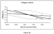
- Figure 2a illustrates one of the requirements that a TSO may give a wind park operator.
- the amount of reactive power that a wind park operator may be required to deliver may vary linearly in accordance with one of the lines shown.
- FIG 2a an example is shown of a wind park of 4950 kVAR and a voltage at the PCC of 33 kV.
- the TSO may, in accordance with circumstance require a wind park operator to deliver reactive power in accordance with one of the straight lines a, b or c shown. More of such lines may be provided by a TSO.
- the corresponding values may be provided to a wind park operator in the form of one or more tables specifying how much reactive power is to be generated in response to varying grid conditions.
- Each of the lines a, b, and c in figure 2a represent a line with a different constant k.
- a TSO may require a certain slope for the straight line (a, b or c), usually in the form of a percentage "g".
- Figure 2b further illustrates a possible central control method in accordance with some embodiments of the invention.
- the values for the constants for the proportional, integral and derivative components may vary, and for some embodiments, some constants may be equal to zero.
- a PID control is however merely one of the possible control methods that may be employed in a central reactive power control system in embodiments of the invention.
- a compensation factor Q com may be added to compensate for the capacitance of the wind park.
- X cci is the reactance of the transformer of a particular wind turbine
- I i is the current in the transformer in a particular wind turbine
- X ccwf is the reactance of the wind park transformer
- I trwf is the current at the wind park transformer.
- the wind park comprises capacitor banks or other reactive power compensation means (such as e.g. inductor banks), and if they are active
- the compensation factor Q com may be added to the central reactive power control demand Q ref .
- the result is a compensated central reactive power control demand Q* ref .
- This central reactive power control demand Q* ref may be input to a despatch function, which determines the amounts of reactive power Q 100 , Q 200 etc. that may be requested from each of the wind turbine local control systems.
- the central control demand Q* ref may simply be divided equally among all wind turbines.
- the central control demand may be divided in such a way that substantially the same percentage of available reactive power is generated at each of the wind turbines.
- the commands sent to each of the local control systems may be determined for example in accordance with the following equations:
- Q nec Q ⁇ ref ⁇ ⁇ 1 ⁇ E i ⁇ Q i ⁇ max
- Q *ref is the compensated central reactive power control demand
- Q imax is the maximum available reactive power for each of the wind turbines and the result Q nec is the amount of reactive power that has to be generated by the wind turbines in central control mode
- Q max total ⁇ i N E i ⁇ F i ⁇ Q i ⁇ max , wherein Q maxtotal is the maximum available amount of reactive power of the wind turbines that are in central control mode and F
- the central control system may send dynamic (non-constant) limit values to the local control systems indicating when a local control system is to switch to a local control mode.
- the local control systems may thus determine themselves to switch to a local control mode and do not need to wait for a particular command to do so.
- the limit values may be determined substantially such that in normal grid conditions, the wind park operates in the central control mode and that in or near exceptional grid conditions, the wind park operates in the local control mode. In exceptional grid conditions, the local control may thus be able to react quicker in response to locally measured parameters.
- I is the current circulating through a particular part of the wind park (e.g stretch of cable, or transformer)
- R is the resistance of the particular part of the wind park
- X is the reactance of a particular part of the wind park
- ⁇ is the power factor angle.
- P active power of the wind park
- Q reactive power of the wind park
- R resistance of transformer
- X reactance of transformer
- U is the nominal voltage at the PCC.
- maximums and minimums for local voltages may be sent to the local control systems of the wind turbines.
- a local voltage for a particular wind turbine reaches or exceeds one of the limit values, this particular wind turbine may switch to a local control mode.
- other wind turbines may still be in central control mode and may continue receiving and following orders of the central control system.
- the wind turbines that are in local control mode may deliver predetermined amounts of reactive power, which may e.g. be the maximum or minimum possible reactive power capacity.
- the method of calculating the limit values by the central control system may be varied.
- the factor 1+0.01g may be limited to a maximum of 1.05, and the factor 1 - 0.01g may be limited to a minimum of 0.95.
- the local limit values may be calculated by the local control systems.
- the local limit values may be constant and may be determined e.g. during a trial or test phase of a wind park.
- a high rate of change of a local voltage may prompt a local control system to switch from a central control mode to a local control mode.
- a sudden change in voltage of certain proportions e.g. a predetermined voltage difference is achieved in a very small time period
- the limit rates of change and/or the limit proportions of sudden changes may be determined by the local control system itself, they may be delivered by the central reactive power control system or may be constant.
- FIG. 3a illustrates a control method in a central control mode according to an embodiment of the present invention.
- the central control method is started and initial values of parameters are determined (e.g. reactance for the wind park components).
- Steps 1001 - 1002 comprise the collection of data from respectively the PCC, and the local control systems. Data that may be collected from the PCC may include (but is not limited to) the voltage at the PCC, current at the PCC, grid frequency, active power generated by the wind park and reactive power generated by the wind park.
- Data that may be collected from one or more of the wind turbines in the park may include (but is not limited to) active power generated, reactive power generated, the status of the wind turbine (operating or not; within operational boundaries or not; in local control mode or in central control mode), the maximum available reactive power capacity (capacitive), the minimum reactive power capacity (inductive), local voltage, current and frequency.
- the maximum and minimum available reactive power may vary with varying local voltage.
- the values for the maximum and minimum available reactive power may be calculated by the local control systems and sent to the central reactive power control system.
- Step 1003 comprises the calculation of the central reactive power control command, and the calculation of the instructions to be sent to the local control systems. This calculation may be e.g. in accordance with Equations 1 and 2. If the grid voltage is outside predefined boundaries (see e.g. figure 2a ), the central reactive power control command may be the maximum or minimum available reactive power for the wind park.
- the instructions sent to a local control system may include, but are not limited to: local reactive power commands (which may in some embodiments be calculated in accordance with equations 3 - 6), local limit values (which may in some embodiments be calculated in accordance with equations 7 - 9), and local limit rates.
- Step 1004 comprises sending the commands indicative of the reactive power to be generated locally to the local control systems.
- the implementation of the commands by the local control systems and varying grid conditions may lead to new values for one or more variables, so that the steps 1001, 1002 and 1003 may be repeated continuously.
- Figure 3b illustrates a control method in a local control system according to some embodiments of the present invention.
- the control method is started.
- certain variables may be measured such as e.g. local voltage, current, active and reactive power.
- the values of these variables may be sent to a central control system.
- Other parameters / variables that may be sent to a central control system may include e.g. the status of the wind turbine (operative or not), the operation status of the wind turbine (within operational boundaries or not), the control mode (central control mode or local control mode).
- control signals for e.g. the converter may be calculated and in a step 2004, these control signals may be sent to the converter.
- the separate method steps are not necessarily sequential, but rather take place continuously and simultaneously. They may each have their own operational speeds and frequencies: in some embodiments, measuring certain variables may take place e.g. every 0.01 s, whereas sending data to the central control system may take place e.g. every 0.3 s.
- Step 2010 comprises receiving local limit values from the central control system and comparing them with instantaneous local variables. The comparison may lead to a determination of "within limits" in step 2011, or "outside limits” in step 2012. If the determination "outside limits" is made, the local control system will switch to a local control mode.
- the local control system will determine the amount of reactive power to be generated (regardless of commands received from a central control system).
- the local control systems may switch back to a central control mode after a predetermined amount of time.
- the amount of time before returning to a central control mode may be determined in accordance with e.g. the slope of the voltage - reactive power line prescribed by a TSO.
- the amount of time before returning to the central control mode may be constant, may be calculated by the central control system, or may be calculated by a local control system.
- the amount of time before returning to the central control mode may in certain embodiments also depend on e.g. the cause of the switch from the central control mode to the local control mode (e.g. voltage value outside limits, rate of change of voltage outside limits, or sudden change in voltage outside limit proportions).
- the local control will switch back to a central control mode when one or more measured variables fulfil a predefined requirement. Also combinations of a time-dependent and variable-dependent return to a central control mode may be used.
- the reactive power control method for the wind park may further be adapted to include algorithms for taking certain wind turbines out of operation if e.g. the wind turbine does not follow the commands of the central control system or e.g. if a particular wind turbine keeps working in (or switching to) local control mode, or if the wind park is unable to deliver the prescribed reactive power values, or e.g. if communication failures are noted etc.
- wind turbines within the same wind park may comprise different local reactive power control systems.
- some local reactive power control systems may be adapted to switch to a local control mode only in response to an instantaneous voltage, whereas other local reactive power control systems switch only in response to (or also in response to) a rate of change of a voltage, yet further reactive local power control systems may be adapted to switch only in response to (or also in response to) voltage jumps of specified proportions.
Landscapes
- Engineering & Computer Science (AREA)
- Power Engineering (AREA)
- Life Sciences & Earth Sciences (AREA)
- Sustainable Development (AREA)
- Sustainable Energy (AREA)
- Chemical & Material Sciences (AREA)
- Combustion & Propulsion (AREA)
- Mechanical Engineering (AREA)
- General Engineering & Computer Science (AREA)
- Control Of Eletrric Generators (AREA)
- Supply And Distribution Of Alternating Current (AREA)
- Wind Motors (AREA)
Description
- The present invention relates to a method for reactive power regulation in a wind park, a method of reactive power regulation in a wind turbine and to a wind park.
- With the increased use of wind energy for electricity generation, grid operators (TSO's or Transmission System Operators) have introduced stricter requirements for wind park operators with respect to active and reactive power generation in support of the grid. For example, wind park operators may be requested to not always generate maximum active power available depending on wind conditions. Also, in accordance with some grid codes, wind parks have to support the grid during a voltage drop and not e.g. disconnect from the grid.
- In this respect, it is known to vary the reactive power generated in a wind park in accordance with a grid voltage at a Point of Common Coupling (PCC). It is also known to vary the active power generated in a wind park in accordance with a measured grid frequency.
-
EP 1 850 002 discloses a wind park comprising a number of fixed speed wind turbines and a number of variable speed wind turbines. The variable speed wind turbines are adapted to equalize an output of the wind park by compensating for a varying output of the fixed speed wind turbines. These variable speed wind turbines may be independent or a central management device may be provided for sending control commands to each of the variable speed wind turbines. -
US 7, 531, 911 discloses a method of reactive power regulation in a wind farm wherein a measured reactive power output of the wind farm is compared to a reactive power set point; based on the difference between them, a reactive power command is generated. The reactive power commands for each of the wind turbines are determined as a percentage of an instantaneous maximum reactive power capacity of each of the turbines. -
US 2008/0073912 discloses a wind park including at least two wind turbines and a park master configured for power factor control and for sending global power coefficient signals to lower level regulators at the wind turbines. -
WO 2005/099063 discloses a method for operating a frequency converter of a generator in particular of a wind energy turbine, in the event of a substantial grid voltage drop, wherein the frequency converter comprises a generator-side power converter, to be connected to the generator, a grid-side power converter to be connected to the voltage grid, and a DC link circuit for connecting the generator-side power converter to the grid-side power converter, comprises the step of generating the amount of reactive current to be supplied to the grid by controlling the frequency converter. -
US 2008/0106099 discloses an interface device transmitting a reactive power command depending on a power system from a voltage regulation device of the power system to a wind power generation apparatus electrically connected to the power system, and the wind power generation apparatus receives the reactive power command. -
WO 2009/083446 discloses a method for operating a wind farm comprising a plurality of wind turbine generators having substantially the same real output power ratings supplying power to a grid. The method comprises the steps of selecting at least one wind turbine in a first group of wind turbines to support reactive power needs of the farm or grid by supplying or absorbing reactive power when needed; selecting at least one turbine in a second group of wind turbines to support reactive power need of the farm or grid by absorbing reactive power when needed; and commanding at least one wind turbine in the first or second group to support reactive power needs of the farm or grid. -
US 2010/0134076 discloses systems and methods for reactive power regulation and voltage support for renewable energy plants. In one embodiment, a system and a method are provided for coordinating voltage and reactive power output of a plant with one or more requirements associated with a utility. -
DE 10 2007 044 601 A1 discloses a windpark with voltage control, where the individual turbines use a superposition of a local reactive power command received from a central controller and a local reactive power command which is generated locally within the windturbine depending on the local grid voltage. Beyond certain boundaries of the local grid voltage the local reactive power command will be the maximum inductive or capacitive reactive power of the windturbine. - In general, prior art control systems are known that are based either on a centralised control or on a decentralised control. An advantage of a centralised control approach may generally be that the control is stable. However a disadvantage of a centralised control may be that such a control is not always able to react sufficiently quickly to grid abnormalities. An advantage of a decentralised control may be that it is quicker to react to grid abnormalities, but a disadvantage can be that the control can be unstable. There thus still exists a need for a power control in a wind farm that can combine stable control with quick reaction capability to grid abnormalities. The present invention is aimed at partially or completely fulfilling this need. Further advantages will become apparent from the description that follows.
- The invention is defined by a method of reactive power regulation in a windpark according to claim 1, a method of reactive power regulation in a wind-turbine according to claim 11 and a wind-turbine according to
claim 15. All the technical features of one of the respective independent claims are mandatory and not optional, irrespective of any statements to the contrary in the following passages. Preferred embodiments are described by the dependent claims. - In a first aspect, the present invention provides a method of reactive power regulation in a wind park connected to an electrical grid, the wind park comprising a plurality of wind turbines and a central reactive power control system, wherein at least a first portion of the plurality of wind turbines comprises a local reactive power control system adapted to work in a central control mode and a local control mode, wherein the central reactive power control system sends commands indicative of local reactive power demands to the local reactive power control systems in accordance with at least one measured variable of the grid; and wherein in a central control mode, a local reactive power control system operates a wind turbine to generate reactive power in accordance with said commands; and wherein in a local control mode, a local reactive power control system determines an amount of reactive power to be generated and controls a wind turbine to generate said amount of reactive power.
- In accordance with this aspect of the invention, a combination of centralised control and decentralised control is provided, combining the advantages of both approaches.
- In some embodiments, a local reactive power control system may switch from the central control mode to the local control mode when a measured local variable passes a local limit value for the wind turbine. An exceptional grid condition will generally be translated in an exceptional grid condition within the wind park. An aspect of these embodiments is that a local control system does not have to wait for a central control system to detect an abnormality and translate that abnormality into control signals. Instead a local control system is able to measure the abnormality and quickly respond. Optionally, the switch to a local control made is only made if the measured local variable passes a local limit value during at least a predetermined period of time. Preferably, the local limit values for each wind turbine are determined substantially such that in normal grid conditions, the wind park operates in the central control mode and that in or near exceptional grid conditions, the wind park operates in the local control mode. An aspect of these embodiments is that in normal grid conditions, the more stable centralised control may be used, whereas in or near exceptional grid conditions, a quicker response with the local control is available. According to these embodiments, in exceptional grid conditions, all wind turbines with local reactive power control systems may be in local control mode or only a part of them. A TSO may determine what "normal" grid conditions are. Any grid condition that is not considered "normal" may be considered "exceptional". An example of an exceptional grid condition may be e.g. a grid voltage outside predefined boundary values.
- In some embodiments, the local limit values for each wind turbine are voltages and said measured local variables are local voltages. In some of these embodiments, local limit values for each wind turbine comprise a minimum and a maximum voltage.
- In some embodiments, the local limit values may be constant. In alternative embodiments, local limit values may be determined in accordance with at least one measured variable.
- In some embodiments, the amount of reactive power generated in a local control mode may be the maximum or minimum amount of reactive power a wind turbine can actually generate. In some embodiments, the local control systems may determine the maximum and minimum amount of reactive power a wind turbine can generate in accordance with operational conditions of the wind park and/or each wind turbine. Conditions that may be taken into account include e.g. thermal conditions of components of the generator and/or converter. Alternatively, the local control systems may use predefined maximum and/or minimums (which will have to be within actual operational limits of the generator and/or converter).
- In some embodiments, a local reactive power control system may switch from the central control mode to the local control mode when an absolute value of a rate of change of a measured local variable (e.g. a local voltage) surpasses a local limit rate. In these embodiments, the local control mode may be activated when a rate of change (either positive or negative) passes a limit rate. Optionally, the local limit rates may be constant. The local limit rates may also be determined in accordance with at least one measured variable.
- In some embodiments, the local reactive control systems switch from the central control mode to the local control mode when a sudden change of a measured local variable surpasses local limit proportions. Optionally, said local limit proportions comprise an absolute local limit difference. In these embodiments, the switch is not necessarily determined by an instantaneous value of a rate of change of a voltage, but rather by a "jump" of a certain size within a certain time. In these embodiments, the rate of change is thus indirectly taken into account.
- In some embodiments, when a local control system switches from a central control mode to a local control mode in response to a rate of change of a measured local variable surpassing a local limit rate, in the local control mode, the amount of reactive power to be generated may be determined in accordance with the registered rate of change and/or operational conditions of the wind park and/or operational conditions of the wind turbine.
- In some embodiments, when a local control system switches from a central control mode to a local control mode in response to a sudden change of a measured local variable surpassing local limit proportions, in the local control mode, the amount of reactive power to be generated may be determined in accordance with the registered sudden change and/or operational conditions of the wind park and/or operational conditions of the wind turbine.
- In some embodiments, the local limit values and/or local limit rates and/or local limit proportions for a sudden change may be calculated periodically (either by a central control system or by the local control systems), or may be provided e.g. by means of a pre-calculated look-up-table. The local limit values and/or local limit rates and/or local limit proportions may also be determined in accordance with an algorithm obtained with an artificial neural network.
- In some embodiments, the local limit values and/or local limit rates and/or local limit proportions for a sudden change of a variable may be determined by the central reactive power control system and supplied to each of the local reactive power control systems. In other embodiments, the local limit values and/or local limit rates and/or local limit proportions may be determined by each of the local reactive power control systems.
- In some embodiments, a local reactive power control system may switch from the local control mode to the central control mode after a predetermined amount of time of operating in the local control mode has passed. In other embodiments, a local reactive power control system may switch from the local control mode to the central control mode in accordance with operational conditions of the wind park and/or electrical grid and/or wind turbines.
- In some embodiments, in the central control mode a central reactive power demand may be determined in response to a measured grid voltage. Optionally the commands indicative of local reactive power demands may be determined by distributing the central reactive power command between the plurality of wind turbines such that each local power control command represents the same percentage of the maximum available local reactive power of each wind turbine. In alternative embodiments, different distribution algorithms or distribution keys may be used.
- In another aspect, the invention provides a method of reactive power regulation in a wind turbine comprising receiving commands indicative of a local reactive power demand from a central reactive power control system; obtaining a maximum and a minimum local voltage; obtaining an instantaneous value of the local voltage from a measuring device and comparing said instantaneous value for the local voltage with the limit values; and if the local voltage is more than the maximum local voltage, sending control commands to at least one wind turbine component for generating the maximum available inductive reactive power; and if the local voltage is less than the minimum local voltage, sending control commands to at least one wind turbine component for generating the maximum available capacitive power. In this aspect, a method of control of a wind turbine is provided that is able to quickly and stably provide support to a grid.
- In some embodiments, the method of reactive power regulation in a wind turbine may further comprise obtaining an absolute rate of change limit of a local voltage, determining a rate of change of a local voltage based on the obtained values of the local voltage from the measuring device, and if the absolute determined voltage rate of change is more than the absolute rate of change limit, locally determining the amount of reactive power to be generated, and sending control commands to at least one wind turbine components for generating said amount of reactive power. In these embodiments, wind turbines are not only quick to react to a particularly high or a particularly low voltage on the grid, also voltage changes are taken into account.
- Optionally, obtaining an absolute rate of change limit of a local voltage comprises receiving the absolute rate of change limit from the central reactive power control system. Another option is that obtaining an absolute rate of change limit of a local voltage comprises calculating the absolute rate of change limit.
- In alternative embodiments, the method further comprises obtaining local limit proportions for a sudden difference in voltage, determining a sudden difference in voltage based on the obtained values of the local values from the measuring device, and if the sudden difference in voltage surpasses the local limit proportions, locally determine the amount of reactive power to be generated, and sending control commands to at least one wind turbine component for generating said mount of reactive power. In these embodiments, wind turbines are able to react quickly to voltage "jumps" (both positive and negative) on the grid.
- In a further aspect, the invention also provides a computer program product comprising program instructions for causing a computing system to perform a method of reactive power regulation in a wind turbine substantially as hereinbefore described. Said computer program may be embodied on storing means (for example, on a record medium, on a computer memory or on a read-only memory) or carried on a carrier signal to be, for example, downloaded from a computer or sent by an email (for example, on an electrical or optical carrier signal).
- In yet another aspect, the invention provides a wind park connected to an electrical grid and comprising a plurality of wind turbines, wherein at least a portion of the plurality of wind turbines comprises a local reactive power control system capable of controlling the reactive power a wind turbine generates, the wind park further comprising a central reactive power control system capable of determining commands indicative of local reactive power demands for each of the local reactive power control systems in response to at least one measured variable of the grid, and sending the commands to the local reactive power control systems, and the local reactive power control systems being adapted to work in a central control mode and a local control mode, wherein in a central control mode, the local reactive power control system controls a wind turbine to generate reactive power in accordance with a command received from the central reactive power control system, and wherein in a local control mode, the local reactive power control system determines an amount of reactive power to be generated by the corresponding wind turbine and controls the wind turbine to generate said amount of reactive power.
- In some embodiments, the local reactive power controls are adapted to control an converter and/or a pitch system.
- In some embodiments, the wind park may comprise additional reactive power compensation means such as e.g. capacitor banks and/or inductor banks, and the central reactive power control may be adapted to control these reactive power compensation means. In these embodiments, the wind park comprises more possibilities to control the generated reactive power.
- In yet another aspect, the invention provides a method of reactive power regulation in a wind turbine comprising receiving commands indicative of a local reactive power control system; obtaining an absolute rate of change limit of a local voltage; obtaining instantaneous values of the local voltage from a measuring device; determining a rate of change of a local voltage based on the obtained values of the local voltage from the measuring device, and if the absolute voltage rate of change is less than the rate of change limit, sending control commands to at least one wind turbine component for generating reactive power in accordance with the commands received from the central reactive power control system; and if the absolute determined voltage rate of change is more than the rate of change limit, locally determining the amount of reactive power to be generated, and sending control commands to at least one wind turbine component for generating said amount of reactive power. And in yet another aspect, the invention provides a method of reactive power regulation in a wind turbine comprising receiving commands indicative of a local reactive power control system; obtaining local limit proportions for a sudden change in local voltage; obtaining instantaneous values of the local voltage from a measuring device; determining a sudden difference in voltage based on the obtained values of the local voltage from the measuring device, and if the sudden change of voltage is less than local limit proportions, sending control commands to at least one wind turbine component for generating reactive power in accordance with the commands received from the central reactive power control system; and if the sudden difference in voltage surpasses the local limit proportions, locally determining the amount of reactive power to be generated, and sending control commands to at least one wind turbine component for generating said amount of reactive power.
- In description of embodiments / examples: In the following description the term "embodiment" may have been used for subject-matter that is not part of the invention as defined by the appended claims. Only those examples that comprise all the features of one of the independent claims are part of the invention and thus embodiments of the invention. Parts of the subject-matter of the description not covered by the claims constitute background art or examples useful for understanding the invention.
- Particular embodiments of the present invention will be described in the following by way of non-limiting examples, with reference to the appended drawings, in which:
-
Figure 1a schematically illustrates a first embodiment of a wind park according to the present invention; -
Figure 1b schematically illustrates communication lines in said first embodiment; -
Figures 2a - 2b illustrate a central reactive power control in accordance with some embodiments of the present invention; -
Figures 3a and 3b illustrate embodiments of control methods in accordance with the present invention in a central control system and a local control system respectively. - Throughout the description reference is made to a maximum or minimum amount of reactive power, to a positive or negative amount of reactive power, as well as to an increase or decrease in reactive power. Within the scope of this description, a positive reactive power is considered capacitive reactive power; a maximum amount of reactive power is thus considered to be the maximum possible capacitive reactive power, and an increase in reactive power is thus considered to be an increase in capacitive power (or a decrease in inductive power). A negative reactive power is considered to be inductive reactive power; a minimum amount of reactive power is thus considered to be the maximum possible inductive reactive power, and a decrease in reactive power is thus considered to be an increase in inductive power (or a decrease in capacitive power).
-
Figure 1a schematically illustrates a wind park comprising n wind turbines, 100, 200...n00. At least a portion of the n wind turbines comprises a local reactivepower control system generator - The wind park further comprises a central reactive
power control system 20. Also the central reactivepower control system 20 may be part of a general central wind park control system or may be a dedicated stand-alone control system. - The wind park is connected to an
electrical grid 10 at a Point of Common Coupling (PCC). Each of the generators of the wind turbines may be connected to the medium voltagewind park grid 40 through asuitable transformer wind park grid 40 may be connected to the High Voltage electrical grid through asuitable transformer 30. - Schematically illustrated with dotted lines are lines of communication between the central reactive
power control system 20 with each of the local reactivepower control systems central control system 20 may send commands to the local control systems. Each of the local control systems is furthermore able to communicate with its corresponding generator and converter (if present). Data from the generator and converter (currents, voltages) may thus be collected by the local control system and the local control system can give commands to control the wind turbine and at least some of its components.Figure 1b schematically illustrates communication lines in said first embodiment. A TSO 5 can communicate its requirements to a wind park central reactivepower control system 20. The central control system may in accordance with one ormore measurements 15 send instructions to a local reactive power control system x20. On the basis of these instructions and on the basis of one or more measurements x15, in this embodiment, the local control system x20 may control a converter control system x22 and a pitch control system x24. The converter control system x22 and pitch control system x24 are able to communicate their functioning to the local control system x20. Controlling both pitch and the converter, the local control system may be able to control e.g. the wind turbine active power, wind turbine speed, the reactive power generation, frequency control, voltage control and LFRT (Line Fault Ride-Through) behaviour. - A
measurement 15 upon which thecentral control 20 may base its instructions may be a grid voltage at or near the PCC. Measurements x15 which may be taken into account by thelocal controls - In accordance with embodiments of the invention, in response to a local measured voltage, the control mode of one or more of the local reactive power control systems may be switched from a central control mode (in which the instructions sent to the local control x20 are followed by the local control system) to a local control mode (in which the local control systems determine amounts of reactive power to be generated and control the wind turbines accordingly). In some embodiments and in some circumstances, the amounts of reactive power to be generated may e.g. be a minimum or a maximum amount of reactive power.
-
Figure 2a illustrates one of the requirements that a TSO may give a wind park operator. Within a certain range of grid voltages, the amount of reactive power that a wind park operator may be required to deliver may vary linearly in accordance with one of the lines shown. Infigure 2a , an example is shown of a wind park of 4950 kVAR and a voltage at the PCC of 33 kV. The TSO may, in accordance with circumstance require a wind park operator to deliver reactive power in accordance with one of the straight lines a, b or c shown. More of such lines may be provided by a TSO. Alternatively, the corresponding values may be provided to a wind park operator in the form of one or more tables specifying how much reactive power is to be generated in response to varying grid conditions. - In general, each of the straight lines a, b and c may be described with the following equation:

figure 2a represent a line with a different constant k. - In practice, a TSO may require a certain slope for the straight line (a, b or c), usually in the form of a percentage "g". The constant k however will depend on the reactive power capacity of the wind park and may be determined in accordance with:

figure 2a , a wind park operator may be required to generate maximum (capacitive) available reactive power or to generate minimum (inductive) available reactive power. In the particular embodiment shown, when the grid voltage is inside the boundaries (and absent other abnormalities), the grid may be said to be in "normal conditions". When the grid voltage is outside the boundaries, the grid may be said to be in "exceptional conditions". The definition of normal grid conditions and exceptional grid conditions may depend on the grid and on the TSO. -
Figure 2b further illustrates a possible central control method in accordance with some embodiments of the invention. Once an amount of required reactive power Q*WF has been determined in accordance with the TSO's requirements, this Q*WF is compared to the amount of reactive power actually generated at that moment QWF. The difference between these two values ("the error") may be input for a PID controller, which generates a central reactive power control command Qref. - For different embodiments of the invention, the values for the constants for the proportional, integral and derivative components may vary, and for some embodiments, some constants may be equal to zero. A PID control is however merely one of the possible control methods that may be employed in a central reactive power control system in embodiments of the invention.
- A compensation factor Qcom may be added to compensate for the capacitance of the wind park. In some embodiments of the invention, the compensation factor Qcom may be determined in accordance with:

- In accordance with
figure 2b , the compensation factor Qcom may be added to the central reactive power control demand Qref. The result is a compensated central reactive power control demand Q*ref. - This central reactive power control demand Q*ref may be input to a despatch function, which determines the amounts of reactive power Q100, Q200 etc. that may be requested from each of the wind turbine local control systems. In accordance with one embodiment, the central control demand Q*ref may simply be divided equally among all wind turbines.
- In accordance with other embodiments, the central control demand may be divided in such a way that substantially the same percentage of available reactive power is generated at each of the wind turbines. The commands sent to each of the local control systems may be determined for example in accordance with the following equations:


- Apart from the amounts of reactive power to be produced by each of the wind turbines having a local control system, other information may also be sent to each of the local control systems. In some embodiments, the central control system may send dynamic (non-constant) limit values to the local control systems indicating when a local control system is to switch to a local control mode. The local control systems may thus determine themselves to switch to a local control mode and do not need to wait for a particular command to do so. The limit values may be determined substantially such that in normal grid conditions, the wind park operates in the central control mode and that in or near exceptional grid conditions, the wind park operates in the local control mode. In exceptional grid conditions, the local control may thus be able to react quicker in response to locally measured parameters. For example, the limit values sent to the local control systems may be determined in accordance with:

- In this embodiment, the adjustment parameter h for wind turbine i may be determined in accordance with:

- The normalized voltage drops for each of the separate components may be calculated in accordance with:

- Wherein I is the current circulating through a particular part of the wind park (e.g stretch of cable, or transformer), R is the resistance of the particular part of the wind park, X is the reactance of a particular part of the wind park and ϕ is the power factor angle.
- Alternatively, the normalized voltage drops may be calculated in accordance with:

- Wherein e.g. for the wind park transformer:
P is active power of the wind park, Q is reactive power of the wind park, R is resistance of transformer and X is reactance of transformer and U is the nominal voltage at the PCC. The voltage drops for each stretch of electrical line and for each wind turbine transformer may be determined in a similar manner using the appropriate resistance, reactance, active power and reactive power. - In the described manner, maximums and minimums for local voltages may be sent to the local control systems of the wind turbines. When a local voltage for a particular wind turbine reaches or exceeds one of the limit values, this particular wind turbine may switch to a local control mode. It should be noted that other wind turbines may still be in central control mode and may continue receiving and following orders of the central control system. The wind turbines that are in local control mode may deliver predetermined amounts of reactive power, which may e.g. be the maximum or minimum possible reactive power capacity.
- Within the scope of the invention, the method of calculating the limit values by the central control system may be varied. For example, in equation 7, the factor 1+0.01g may be limited to a maximum of 1.05, and the factor 1 - 0.01g may be limited to a minimum of 0.95. Other variations are also possible. Also, in some embodiments of the invention, the local limit values may be calculated by the local control systems. In other embodiments, the local limit values may be constant and may be determined e.g. during a trial or test phase of a wind park.
- In further embodiments of the invention, a high rate of change of a local voltage may prompt a local control system to switch from a central control mode to a local control mode. In another example, a sudden change in voltage of certain proportions (e.g. a predetermined voltage difference is achieved in a very small time period) may prompt such a switch. The limit rates of change and/or the limit proportions of sudden changes may be determined by the local control system itself, they may be delivered by the central reactive power control system or may be constant.
-
Figure 3a illustrates a control method in a central control mode according to an embodiment of the present invention. Instep 1000, the central control method is started and initial values of parameters are determined (e.g. reactance for the wind park components). Steps 1001 - 1002 comprise the collection of data from respectively the PCC, and the local control systems. Data that may be collected from the PCC may include (but is not limited to) the voltage at the PCC, current at the PCC, grid frequency, active power generated by the wind park and reactive power generated by the wind park. - Data that may be collected from one or more of the wind turbines in the park may include (but is not limited to) active power generated, reactive power generated, the status of the wind turbine (operating or not; within operational boundaries or not; in local control mode or in central control mode), the maximum available reactive power capacity (capacitive), the minimum reactive power capacity (inductive), local voltage, current and frequency. The maximum and minimum available reactive power may vary with varying local voltage. The values for the maximum and minimum available reactive power may be calculated by the local control systems and sent to the central reactive power control system.
-
Step 1003 comprises the calculation of the central reactive power control command, and the calculation of the instructions to be sent to the local control systems. This calculation may be e.g. in accordance with Equations 1 and 2. If the grid voltage is outside predefined boundaries (see e.g.figure 2a ), the central reactive power control command may be the maximum or minimum available reactive power for the wind park. - The instructions sent to a local control system may include, but are not limited to: local reactive power commands (which may in some embodiments be calculated in accordance with equations 3 - 6), local limit values (which may in some embodiments be calculated in accordance with equations 7 - 9), and local limit rates.
-
Step 1004 comprises sending the commands indicative of the reactive power to be generated locally to the local control systems. The implementation of the commands by the local control systems and varying grid conditions may lead to new values for one or more variables, so that thesteps -
Figure 3b illustrates a control method in a local control system according to some embodiments of the present invention. In amethod step 2000, the control method is started. In astep 2001, certain variables may be measured such as e.g. local voltage, current, active and reactive power. In astep 2002, the values of these variables may be sent to a central control system. Other parameters / variables that may be sent to a central control system may include e.g. the status of the wind turbine (operative or not), the operation status of the wind turbine (within operational boundaries or not), the control mode (central control mode or local control mode). - In a
step 2003, control signals for e.g. the converter may be calculated and in astep 2004, these control signals may be sent to the converter. As may be seen infigure 3b , the separate method steps are not necessarily sequential, but rather take place continuously and simultaneously. They may each have their own operational speeds and frequencies: in some embodiments, measuring certain variables may take place e.g. every 0.01 s, whereas sending data to the central control system may take place e.g. every 0.3 s.Step 2010 comprises receiving local limit values from the central control system and comparing them with instantaneous local variables. The comparison may lead to a determination of "within limits" instep 2011, or "outside limits" instep 2012. If the determination "outside limits" is made, the local control system will switch to a local control mode. - Once the local reactive power control system has switched to local control mode, the local control system will determine the amount of reactive power to be generated (regardless of commands received from a central control system). In some embodiments, the local control systems may switch back to a central control mode after a predetermined amount of time. The amount of time before returning to a central control mode may be determined in accordance with e.g. the slope of the voltage - reactive power line prescribed by a TSO. The amount of time before returning to the central control mode may be constant, may be calculated by the central control system, or may be calculated by a local control system. The amount of time before returning to the central control mode may in certain embodiments also depend on e.g. the cause of the switch from the central control mode to the local control mode (e.g. voltage value outside limits, rate of change of voltage outside limits, or sudden change in voltage outside limit proportions). When switching back to a central control mode, if the determination "outside limits" is made again, the local control mode will be resumed.
- In other embodiments, the local control will switch back to a central control mode when one or more measured variables fulfil a predefined requirement. Also combinations of a time-dependent and variable-dependent return to a central control mode may be used.
- The reactive power control method for the wind park may further be adapted to include algorithms for taking certain wind turbines out of operation if e.g. the wind turbine does not follow the commands of the central control system or e.g. if a particular wind turbine keeps working in (or switching to) local control mode, or if the wind park is unable to deliver the prescribed reactive power values, or e.g. if communication failures are noted etc.
- Furthermore, in embodiments of the invention, wind turbines within the same wind park may comprise different local reactive power control systems. For example, some local reactive power control systems may be adapted to switch to a local control mode only in response to an instantaneous voltage, whereas other local reactive power control systems switch only in response to (or also in response to) a rate of change of a voltage, yet further reactive local power control systems may be adapted to switch only in response to (or also in response to) voltage jumps of specified proportions.
- Although this invention has been disclosed in the context of certain preferred embodiments and examples, it will be understood by those skilled in the art that the present invention extends beyond the specifically disclosed embodiments to other alternative embodiments and/or uses of the invention and obvious modifications and equivalents thereof. Thus, it is intended that the scope of the present invention is defined by the appended claims.
Claims (15)
- A method of reactive power regulation in a wind park connected to an electrical grid (10),
the wind park comprising a plurality of wind turbines (100, 200...n00) and a central reactive power control system (20), wherein at least a first portion of the plurality of wind turbines (100, 200...n00) comprises a local reactive power control system (120, 220 ... n20, x20), characterised in that
the local reactive power control system is adapted to switch between a central control mode and a local control mode and work either in the central control mode or the local control mode, wherein
the central reactive power control system (20) sends commands indicative of local reactive power demands to the local reactive power control systems (120, 220 ... n20) in accordance with at least one measured variable (15) of the grid (10), and wherein
in a central control mode, the local reactive power control system (120, 220 ... n20) operates a wind turbine (100, 200...n00) to generate reactive power in accordance with the commands indicative of local reactive power demands received from the central reactive power control system (20), and wherein
in a local control mode, the local reactive power control system (120, 220 ... n20, x20) receives the commands indicative of local reactive power demands from the central reactive power control system (20), and determines an amount of reactive power to be generated regardless of said commands indicative of local reactive power demands received from said central control system and controls a wind turbine (100, 200...n00) to generate said amount of reactive power, and wherein
a local reactive power control system (120, 220...n20) switches from the central control mode to the local control mode when a measured local variable (x15) passes a local limit value for the wind turbine (100, 200...n00) during at least a predetermined period of time, and
wherein said local limit values for each wind turbine (100, 200...n00) are determined substantially such that in normal grid conditions, the wind park operates in the central control mode and that in or near exceptional grid conditions, the wind park operates in the local control mode, and
wherein in the local control mode, the amount of reactive power to be generated is the maximum or minimum amount of reactive power a wind turbine (100, 200...n00) can generate. - A method according to claim 1, wherein said local limit values for each wind turbine are voltages and said measured local variables (x15) are local voltages and, wherein said local limit values for each wind turbine , optionally, comprise a minimum and a maximum voltage.
- A method according to claim 1 or 2, wherein said local limit values are constant or are determined in accordance with at least one measured variable (X15).
- A method according to any previous claim, wherein said maximum and minimum amount of reactive power a wind turbine (100, 200...n00) can generate are determined in accordance with operational conditions of the wind park and/or the wind turbine.
- A method according to any of claims 1 - 4, wherein a local reactive power control system (120, 220...n20, x20) switches from the central control mode to the local control mode when an absolute value of a rate of change of a measured local variable (x15) surpasses a local limit rate or, when a sudden change of a measured local variable (x15) surpasses local limit proportions, wherein said local limit proportions, optionally, comprise an absolute local limit difference.
- A method according to claim 5, wherein the measured local variable (x15) is a local voltage.
- A method according to any of claims 5 or 6, wherein the local limit values and/or local limit rates and/or local limit proportions are determined using a look-up-table or are calculated periodically.
- A method according to any of claims 1 - 7, wherein said local limit values and/or said local limit rates and/or local limit proportions are determined by the central reactive power control system and supplied to each of the local reactive power control systems, or are determined by each of the local reactive power control systems.
- A method according to any previous claim, wherein the local reactive power control systems (120, 220...n20, x20) switch from the local control mode to the central control mode after a predetermined amount of time of operating in the local control mode has passed and, wherein said predetermined amount of time is, optionally, calculated by a local reactive power control system (120, 220...n20, x20) and, wherein the predetermined amount of time, optionally, depends on the cause of switching from the central control mode to the local control mode.
- A method according to any previous claim, wherein the local reactive power control systems (120, 220...n20, x20) switch from the local control mode to the central control mode in accordance with operational conditions of the wind park and/or electrical grid (10) and/or wind turbines (100, 200...n00).
- A method of reactive power regulation in a wind turbine (100, 200...n00) comprising
receiving commands indicative of a local reactive power demand (Q*WF) from a central reactive power control system (20),
obtaining a maximum and a minimum local voltage,
obtaining an instantaneous value of the local voltage from a measuring device and comparing said instantaneous value for the local voltage with the limit values, and characterised in that, if the local voltage is between the maximum and minimum local voltage, working in a central control mode by sending control commands to at least one wind turbine component for generating the local reactive power demand received from the central reactive power control system (20), and
if the local voltage is more than the maximum local voltage during at least a predetermined period of time, working in a local control mode by sending control commands to at least one wind turbine component for generating the maximum available inductive reactive power regardless of said commands indicative of local reactive power demand received from the central reactive power control system (20), and
if the local voltage is less than the minimum local voltage during at least a predetermined period of time, working in the local control mode by sending control commands to at least one wind turbine component for generating the maximum available capacitive power regardless of the said commands indicative of local reactive power demand received from the central reactive power control system (20). - A method according to claim 11, further comprising obtaining an absolute rate of change limit of a local voltage,
determining a rate of change of a local voltage based on the obtained values of the local voltage from the measuring device, and
if the absolute determined voltage rate of change is more than the absolute rate of change limit, locally determining the amount of reactive power to be generated, and sending control commands to at least one wind turbine component for generating said amount of reactive power. - A method according to claim 11 or 12, wherein if the absolute determined voltage rate of change is less than the absolute rate of change limit and the local voltage is between the maximum and the minimum local voltage,
sending control commands to at least one wind turbine component for generating reactive power in accordance with the commands received from the central reactive power control system (20). - A computer program product comprising program instructions for causing a computing system in a wind turbine comprising a local reactive power control system (120, 220 ... n20, x20) as described in claim 15 to perform a method according to any of claims 11 - 13 and wherein the computer program product is, optionally, embodied on storing means or carried on a carrier signal.
- A wind park connected to an electrical grid (10) and comprising a plurality of wind turbines (100, 200...n00), wherein
at least a portion of the plurality of wind turbines comprises a local reactive power control system (120, 220...n20, x20) configured to control the reactive power (QWF) a wind turbine generates, the wind park further comprising
a central reactive power control system (20) configured to determine commands indicative of local reactive power demands for each of the local reactive power control systems (120, 220...n20, x20) in response to at least one measured variable of the grid, and configured to send the commands to the local reactive power control systems 120, 220...n20, x20), characterised by
the local reactive power control systems (120, 220...n20, x20) being adapted to switch between a central control mode and a local control mode and work either in the central control mode or the local control mode, wherein
in a central control mode, the local reactive power control system (120, 220...n20, x20) is configured to control a wind turbine (100, 200...n00) to generate reactive power in accordance with a command indicative of local reactive power demand received from the central reactive power control system (120, 220...n20, x20), and wherein
in a local control mode, the local reactive power control system (120, 220...n20, x20) is configured to determine an amount of reactive power to be generated by the corresponding wind turbine regardless of commands indicative of local reactive power demand received from a central control system and configured to control the wind turbine to generate said amount of reactive power, wherein
a local reactive power control system (120, 220...n20) is configured to switch from the central control mode to the local control mode when a measured local variable (x15) passes a local limit value for the wind turbine (100, 200...n00) during at least a predetermined period of time, and
wherein said local limit values for each wind turbine (100, 200...n00) are determined such that in normal grid conditions, the wind park is configured to operate in the central control mode and that in or near exceptional grid conditions, the wind park is configured to operate in the local control mode, and
wherein in the local control mode, the amount of reactive power to be generated is configured to be the maximum or minimum amount of reactive power a wind turbine (100, 200...n00) can generate.
Applications Claiming Priority (1)
| Application Number | Priority Date | Filing Date | Title |
|---|---|---|---|
| PCT/EP2010/061233 WO2012016585A1 (en) | 2010-08-02 | 2010-08-02 | Reactive power regulation of a windpark |
Publications (2)
| Publication Number | Publication Date |
|---|---|
| EP2601720A1 EP2601720A1 (en) | 2013-06-12 |
| EP2601720B1 true EP2601720B1 (en) | 2019-11-13 |
Family
ID=43639900
Family Applications (1)
| Application Number | Title | Priority Date | Filing Date |
|---|---|---|---|
| EP10737586.7A Active EP2601720B1 (en) | 2010-08-02 | 2010-08-02 | Reactive power regulation of a windpark |
Country Status (7)
| Country | Link |
|---|---|
| US (1) | US8912675B2 (en) |
| EP (1) | EP2601720B1 (en) |
| CN (1) | CN103053088B (en) |
| BR (1) | BR112013002727B1 (en) |
| DK (1) | DK2601720T3 (en) |
| ES (1) | ES2771073T3 (en) |
| WO (1) | WO2012016585A1 (en) |
Families Citing this family (38)
| Publication number | Priority date | Publication date | Assignee | Title |
|---|---|---|---|---|
| US10103661B2 (en) * | 2011-09-28 | 2018-10-16 | Vestas Wind Systems A/S | Wind power plant and a method for operating thereof |
| EP2629386B1 (en) * | 2012-02-16 | 2018-01-10 | GE Renewable Technologies | Method for avoiding voltage instability in an electrical grid of an offshore wind park |
| US9631608B2 (en) * | 2012-06-12 | 2017-04-25 | Vestas Wind Systems A/S | Wind-power-plant control upon low-voltage grid faults |
| EP2693589B1 (en) * | 2012-07-31 | 2015-02-25 | Siemens Aktiengesellschaft | Wind park control system |
| US9407186B2 (en) | 2012-09-17 | 2016-08-02 | Vestas Wind Systems, A/S | Method of determining individual set points in a power plant controller, and a power plant controller |
| EP2904684B1 (en) * | 2012-10-08 | 2024-06-12 | Vestas Wind Systems A/S | Controller and method for line reactance compensation |
| DE102013210812A1 (en) * | 2013-06-10 | 2014-12-11 | Wobben Properties Gmbh | Method for feeding electrical power into an electrical supply network |
| US10283962B2 (en) | 2013-07-25 | 2019-05-07 | General Electric Company | Systems and methods for reactive power compensation |
| JP5946810B2 (en) * | 2013-10-18 | 2016-07-06 | 三菱重工業株式会社 | Electric power system, operation method thereof, and electric power system control apparatus |
| CN105794068B (en) | 2013-11-28 | 2019-09-13 | 维斯塔斯风力系统集团公司 | Control of reactive power in wind power plants |
| CN105830303B (en) * | 2013-11-28 | 2019-02-26 | 维斯塔斯风力系统集团公司 | Reconfiguration of reactive power circuits of wind power plants |
| US10116138B2 (en) * | 2013-12-11 | 2018-10-30 | Vestas Wind Systems A/S | Wind power plant, and a method for controlling a reactive current injection in a wind power plant |
| ES2847901T3 (en) * | 2014-02-06 | 2021-08-04 | Ge Renewable Tech Wind Bv | Operating procedures for a set of wind turbines and systems |
| US9780710B2 (en) * | 2014-04-15 | 2017-10-03 | General Electric Company | Reactive power control for wind turbine generators |
| CN103997045B (en) * | 2014-05-30 | 2016-08-24 | 中国能源建设集团广东省电力设计研究院有限公司 | The collocation method of Reactive Compensation in Wind Farm and system |
| US20160087442A1 (en) * | 2014-07-04 | 2016-03-24 | Stefan Matan | Modular power grid |
| US11063431B2 (en) | 2014-07-04 | 2021-07-13 | Apparent Labs Llc | Hierarchical and distributed power grid control |
| WO2016034178A1 (en) * | 2014-09-02 | 2016-03-10 | Vestas Wind Systems A/S | A control system for a wind turbine generator |
| CN107429669B (en) | 2015-02-12 | 2020-07-07 | 维斯塔斯风力系统集团公司 | Control system with local and central controllers for a wind turbine system with multiple rotors |
| CN109314395B (en) * | 2016-06-13 | 2022-07-05 | 维斯塔斯风力系统集团公司 | Improvements relating to interconnection of multiple renewable energy power plants |
| US10218178B2 (en) * | 2016-07-07 | 2019-02-26 | University Of Hawai'i | Dynamic reactive compensation |
| CN108808725B (en) * | 2017-05-05 | 2023-03-21 | 通用电气公司 | System and method for reactive power control of wind farm |
| CN107611986A (en) * | 2017-10-13 | 2018-01-19 | 远景能源(江苏)有限公司 | A kind of method of wind power plant operation |
| US10570882B2 (en) | 2017-11-13 | 2020-02-25 | General Electric Company | Dynamic active and reactive power capability for wind farms |
| US11437813B2 (en) * | 2018-11-05 | 2022-09-06 | Rolls-Royce North American Technologies Inc. | System controller for a hybrid aircraft propulsion system |
| US10826297B2 (en) * | 2018-11-06 | 2020-11-03 | General Electric Company | System and method for wind power generation and transmission in electrical power systems |
| AU2019284124B2 (en) * | 2018-12-31 | 2025-08-14 | Nordex Energy Spain, S.A.U. | Wind Farm Control System and Associated Method, Wind Turbine Control System and Associated Method |
| US10767630B1 (en) * | 2019-05-28 | 2020-09-08 | General Electric Company | System and method for operating a wind farm during low wind speeds |
| US11268496B2 (en) | 2019-08-09 | 2022-03-08 | Inventus Holdings, Llc | Distributed wind park control |
| CN112952893B (en) * | 2019-11-26 | 2022-09-23 | 北京金风科创风电设备有限公司 | Reactive power control method and device for wind turbine generator and wind power plant |
| EP3832128A1 (en) * | 2019-12-03 | 2021-06-09 | Wobben Properties GmbH | Method for controlling a wind farm |
| US11152787B2 (en) | 2020-01-10 | 2021-10-19 | General Electric Company | System of modular reactive power compensators |
| CN111463798B (en) * | 2020-04-08 | 2024-02-13 | 长园深瑞继保自动化有限公司 | Grid voltage fuzzy control method for energy storage coordination control device |
| CN113852131B (en) * | 2020-06-28 | 2024-10-18 | 金风科技股份有限公司 | Power control method and device for wind farm |
| WO2022002322A1 (en) | 2020-06-29 | 2022-01-06 | Vestas Wind Systems A/S | Methods and control systems for voltage control of renewable energy generators |
| US11726436B2 (en) * | 2021-08-19 | 2023-08-15 | General Electric Renovables Espana, S.L. | System and method for controlling a power generating system |
| EP4585801A1 (en) * | 2024-01-12 | 2025-07-16 | Siemens Gamesa Renewable Energy A/S | Controlling wind turbines in case of a utility grid event |
| CN121332598B (en) * | 2025-09-29 | 2026-04-24 | 成都康派斯特科技有限公司 | Multi-node reactive compensation control system based on master-slave cooperation |
Citations (1)
| Publication number | Priority date | Publication date | Assignee | Title |
|---|---|---|---|---|
| DE102007044601A1 (en) * | 2007-09-19 | 2009-04-09 | Repower Systems Ag | Wind farm with voltage regulation of wind turbines and operating procedures |
Family Cites Families (17)
| Publication number | Priority date | Publication date | Assignee | Title |
|---|---|---|---|---|
| US6181099B1 (en) * | 1999-12-03 | 2001-01-30 | General Electric Company | Method and apparatus for correcting DC offset in a frequency to voltage converter and motor drive using the same |
| DE10137272A1 (en) * | 2001-07-31 | 2003-02-27 | Aloys Wobben | Early warning system for wind turbines |
| US6915220B2 (en) * | 2003-04-01 | 2005-07-05 | General Electric Company | Integrated, self-powered battery monitoring device and system |
| DE602004027668D1 (en) | 2004-03-12 | 2010-07-22 | Gen Electric | METHOD FOR OPERATING A FREQUENCY TRANSMITTER OF A GENERATOR AND A WIND ENERGY TURBINE WITH A GENERATOR OPERATED ACCORDING TO THE METHOD |
| DE102004048341A1 (en) | 2004-10-01 | 2006-04-13 | Repower Systems Ag | Wind farm with robust reactive power regulation and method of operation |
| US7298059B2 (en) * | 2004-12-17 | 2007-11-20 | General Electric Company | System and method for operating a wind farm under high wind speed conditions |
| JP4495001B2 (en) | 2005-02-17 | 2010-06-30 | 三菱重工業株式会社 | Power generation system |
| US7342323B2 (en) * | 2005-09-30 | 2008-03-11 | General Electric Company | System and method for upwind speed based control of a wind turbine |
| US7505833B2 (en) * | 2006-03-29 | 2009-03-17 | General Electric Company | System, method, and article of manufacture for controlling operation of an electrical power generation system |
| US7642666B2 (en) * | 2006-11-02 | 2010-01-05 | Hitachi, Ltd. | Wind power generation apparatus, wind power generation system and power system control apparatus |
| US7531911B2 (en) | 2006-12-22 | 2009-05-12 | Ingeteam Energy, S.A. | Reactive power control for operating a wind farm |
| WO2009083446A2 (en) * | 2007-12-28 | 2009-07-09 | Vestas Wind Systems A/S | Apparatus and method for controlling reactive power from clusters of wind turbines connected to a utility grid |
| US7994658B2 (en) * | 2008-02-28 | 2011-08-09 | General Electric Company | Windfarm collector system loss optimization |
| US7999406B2 (en) * | 2008-02-29 | 2011-08-16 | General Electric Company | Wind turbine plant high wind derating control |
| US7839024B2 (en) * | 2008-07-29 | 2010-11-23 | General Electric Company | Intra-area master reactive controller for tightly coupled windfarms |
| US8025476B2 (en) * | 2009-09-30 | 2011-09-27 | General Electric Company | System and methods for controlling a wind turbine |
| US7923862B2 (en) * | 2009-10-06 | 2011-04-12 | General Electric Company | Reactive power regulation and voltage support for renewable energy plants |
-
2010
- 2010-08-02 WO PCT/EP2010/061233 patent/WO2012016585A1/en not_active Ceased
- 2010-08-02 EP EP10737586.7A patent/EP2601720B1/en active Active
- 2010-08-02 ES ES10737586T patent/ES2771073T3/en active Active
- 2010-08-02 DK DK10737586.7T patent/DK2601720T3/en active
- 2010-08-02 CN CN201080068399.7A patent/CN103053088B/en active Active
- 2010-08-02 BR BR112013002727-4A patent/BR112013002727B1/en active IP Right Grant
- 2010-08-02 US US13/813,413 patent/US8912675B2/en active Active
Patent Citations (1)
| Publication number | Priority date | Publication date | Assignee | Title |
|---|---|---|---|---|
| DE102007044601A1 (en) * | 2007-09-19 | 2009-04-09 | Repower Systems Ag | Wind farm with voltage regulation of wind turbines and operating procedures |
Also Published As
| Publication number | Publication date |
|---|---|
| BR112013002727A2 (en) | 2016-05-31 |
| US8912675B2 (en) | 2014-12-16 |
| ES2771073T3 (en) | 2020-07-06 |
| WO2012016585A1 (en) | 2012-02-09 |
| BR112013002727B1 (en) | 2020-01-14 |
| DK2601720T3 (en) | 2020-02-24 |
| BR112013002727A8 (en) | 2018-06-12 |
| US20140062086A1 (en) | 2014-03-06 |
| CN103053088A (en) | 2013-04-17 |
| CN103053088B (en) | 2016-02-17 |
| EP2601720A1 (en) | 2013-06-12 |
Similar Documents
| Publication | Publication Date | Title |
|---|---|---|
| US8912675B2 (en) | Reactive power regulation | |
| EP2494671B1 (en) | Wind power plant with optimal power output | |
| US9366227B2 (en) | Control of electric output of a wind park | |
| US9997922B2 (en) | Method for feeding electrical power into an electrical supply network | |
| KR101919273B1 (en) | Method for feeding electrical power into an electric supply network | |
| EP3316433B1 (en) | Voltage control at windfarms | |
| CN113381440B (en) | Method for feeding in electrical power by means of a wind energy system | |
| CN109314395B (en) | Improvements relating to interconnection of multiple renewable energy power plants | |
| EP3669433B1 (en) | Improvements relating to reactive power control in wind power plants | |
| CA2813046C (en) | Wind farm and method for operating a wind farm | |
| KR20160002958A (en) | Method for controlling a wind park | |
| WO2021249603A1 (en) | Hybrid power plant fast frequency response | |
| US9871382B2 (en) | Method and controller for continuously operating a plurality of electric energy generating machines during a high voltage condition | |
| KR20140078230A (en) | Method for compensating reactive power of onshore wind power generator in low voltage ride through of the power grid | |
| US12113363B2 (en) | Control of a renewable energy power plant to resume normal operation following a fault | |
| KR20140078229A (en) | Method for compensating reactive power of offshore wind power generator in low voltage ride through of the power grid | |
| KR20150112540A (en) | Secondary voltage control system and method of power system integrated with wind power plant |
Legal Events
| Date | Code | Title | Description |
|---|---|---|---|
| PUAI | Public reference made under article 153(3) epc to a published international application that has entered the european phase |
Free format text: ORIGINAL CODE: 0009012 |
|
| 17P | Request for examination filed |
Effective date: 20130304 |
|
| AK | Designated contracting states |
Kind code of ref document: A1 Designated state(s): AL AT BE BG CH CY CZ DE DK EE ES FI FR GB GR HR HU IE IS IT LI LT LU LV MC MK MT NL NO PL PT RO SE SI SK SM TR |
|
| DAX | Request for extension of the european patent (deleted) | ||
| 17Q | First examination report despatched |
Effective date: 20160223 |
|
| RAP1 | Party data changed (applicant data changed or rights of an application transferred) |
Owner name: GE RENEWABLE TECHNOLOGIES |
|
| STAA | Information on the status of an ep patent application or granted ep patent |
Free format text: STATUS: EXAMINATION IS IN PROGRESS |
|
| RAP1 | Party data changed (applicant data changed or rights of an application transferred) |
Owner name: GE RENEWABLE TECHNOLOGIES WIND B.V. |
|
| REG | Reference to a national code |
Ref country code: DE Ref legal event code: R079 Ref document number: 602010061938 Country of ref document: DE Free format text: PREVIOUS MAIN CLASS: H02J0003180000 Ipc: H02J0003500000 |
|
| GRAP | Despatch of communication of intention to grant a patent |
Free format text: ORIGINAL CODE: EPIDOSNIGR1 |
|
| STAA | Information on the status of an ep patent application or granted ep patent |
Free format text: STATUS: GRANT OF PATENT IS INTENDED |
|
| RIC1 | Information provided on ipc code assigned before grant |
Ipc: H02J 3/50 20060101AFI20190510BHEP Ipc: H02J 3/18 20060101ALI20190510BHEP Ipc: F03D 9/25 20160101ALI20190510BHEP Ipc: F03D 7/04 20060101ALN20190510BHEP Ipc: F03D 7/02 20060101ALN20190510BHEP Ipc: H02J 3/38 20060101ALI20190510BHEP |
|
| INTG | Intention to grant announced |
Effective date: 20190612 |
|
| GRAS | Grant fee paid |
Free format text: ORIGINAL CODE: EPIDOSNIGR3 |
|
| GRAA | (expected) grant |
Free format text: ORIGINAL CODE: 0009210 |
|
| STAA | Information on the status of an ep patent application or granted ep patent |
Free format text: STATUS: THE PATENT HAS BEEN GRANTED |
|
| AK | Designated contracting states |
Kind code of ref document: B1 Designated state(s): AL AT BE BG CH CY CZ DE DK EE ES FI FR GB GR HR HU IE IS IT LI LT LU LV MC MK MT NL NO PL PT RO SE SI SK SM TR |
|
| REG | Reference to a national code |
Ref country code: GB Ref legal event code: FG4D |
|
| REG | Reference to a national code |
Ref country code: CH Ref legal event code: EP Ref country code: AT Ref legal event code: REF Ref document number: 1202676 Country of ref document: AT Kind code of ref document: T Effective date: 20191115 |
|
| REG | Reference to a national code |
Ref country code: DE Ref legal event code: R096 Ref document number: 602010061938 Country of ref document: DE |
|
| REG | Reference to a national code |
Ref country code: IE Ref legal event code: FG4D |
|
| REG | Reference to a national code |
Ref country code: DK Ref legal event code: T3 Effective date: 20200217 |
|
| REG | Reference to a national code |
Ref country code: NL Ref legal event code: MP Effective date: 20191113 |
|
| REG | Reference to a national code |
Ref country code: LT Ref legal event code: MG4D |
|
| PG25 | Lapsed in a contracting state [announced via postgrant information from national office to epo] |
Ref country code: NO Free format text: LAPSE BECAUSE OF FAILURE TO SUBMIT A TRANSLATION OF THE DESCRIPTION OR TO PAY THE FEE WITHIN THE PRESCRIBED TIME-LIMIT Effective date: 20200213 Ref country code: PL Free format text: LAPSE BECAUSE OF FAILURE TO SUBMIT A TRANSLATION OF THE DESCRIPTION OR TO PAY THE FEE WITHIN THE PRESCRIBED TIME-LIMIT Effective date: 20191113 Ref country code: GR Free format text: LAPSE BECAUSE OF FAILURE TO SUBMIT A TRANSLATION OF THE DESCRIPTION OR TO PAY THE FEE WITHIN THE PRESCRIBED TIME-LIMIT Effective date: 20200214 Ref country code: NL Free format text: LAPSE BECAUSE OF FAILURE TO SUBMIT A TRANSLATION OF THE DESCRIPTION OR TO PAY THE FEE WITHIN THE PRESCRIBED TIME-LIMIT Effective date: 20191113 Ref country code: LT Free format text: LAPSE BECAUSE OF FAILURE TO SUBMIT A TRANSLATION OF THE DESCRIPTION OR TO PAY THE FEE WITHIN THE PRESCRIBED TIME-LIMIT Effective date: 20191113 Ref country code: PT Free format text: LAPSE BECAUSE OF FAILURE TO SUBMIT A TRANSLATION OF THE DESCRIPTION OR TO PAY THE FEE WITHIN THE PRESCRIBED TIME-LIMIT Effective date: 20200313 Ref country code: LV Free format text: LAPSE BECAUSE OF FAILURE TO SUBMIT A TRANSLATION OF THE DESCRIPTION OR TO PAY THE FEE WITHIN THE PRESCRIBED TIME-LIMIT Effective date: 20191113 Ref country code: SE Free format text: LAPSE BECAUSE OF FAILURE TO SUBMIT A TRANSLATION OF THE DESCRIPTION OR TO PAY THE FEE WITHIN THE PRESCRIBED TIME-LIMIT Effective date: 20191113 Ref country code: BG Free format text: LAPSE BECAUSE OF FAILURE TO SUBMIT A TRANSLATION OF THE DESCRIPTION OR TO PAY THE FEE WITHIN THE PRESCRIBED TIME-LIMIT Effective date: 20200213 Ref country code: FI Free format text: LAPSE BECAUSE OF FAILURE TO SUBMIT A TRANSLATION OF THE DESCRIPTION OR TO PAY THE FEE WITHIN THE PRESCRIBED TIME-LIMIT Effective date: 20191113 |
|
| PG25 | Lapsed in a contracting state [announced via postgrant information from national office to epo] |
Ref country code: HR Free format text: LAPSE BECAUSE OF FAILURE TO SUBMIT A TRANSLATION OF THE DESCRIPTION OR TO PAY THE FEE WITHIN THE PRESCRIBED TIME-LIMIT Effective date: 20191113 Ref country code: IS Free format text: LAPSE BECAUSE OF FAILURE TO SUBMIT A TRANSLATION OF THE DESCRIPTION OR TO PAY THE FEE WITHIN THE PRESCRIBED TIME-LIMIT Effective date: 20200313 |
|
| PG25 | Lapsed in a contracting state [announced via postgrant information from national office to epo] |
Ref country code: AL Free format text: LAPSE BECAUSE OF FAILURE TO SUBMIT A TRANSLATION OF THE DESCRIPTION OR TO PAY THE FEE WITHIN THE PRESCRIBED TIME-LIMIT Effective date: 20191113 |
|
| REG | Reference to a national code |
Ref country code: ES Ref legal event code: FG2A Ref document number: 2771073 Country of ref document: ES Kind code of ref document: T3 Effective date: 20200706 |
|
| PG25 | Lapsed in a contracting state [announced via postgrant information from national office to epo] |
Ref country code: EE Free format text: LAPSE BECAUSE OF FAILURE TO SUBMIT A TRANSLATION OF THE DESCRIPTION OR TO PAY THE FEE WITHIN THE PRESCRIBED TIME-LIMIT Effective date: 20191113 Ref country code: RO Free format text: LAPSE BECAUSE OF FAILURE TO SUBMIT A TRANSLATION OF THE DESCRIPTION OR TO PAY THE FEE WITHIN THE PRESCRIBED TIME-LIMIT Effective date: 20191113 Ref country code: CZ Free format text: LAPSE BECAUSE OF FAILURE TO SUBMIT A TRANSLATION OF THE DESCRIPTION OR TO PAY THE FEE WITHIN THE PRESCRIBED TIME-LIMIT Effective date: 20191113 |
|
| REG | Reference to a national code |
Ref country code: DE Ref legal event code: R097 Ref document number: 602010061938 Country of ref document: DE |
|
| REG | Reference to a national code |
Ref country code: AT Ref legal event code: MK05 Ref document number: 1202676 Country of ref document: AT Kind code of ref document: T Effective date: 20191113 |
|
| PG25 | Lapsed in a contracting state [announced via postgrant information from national office to epo] |
Ref country code: SK Free format text: LAPSE BECAUSE OF FAILURE TO SUBMIT A TRANSLATION OF THE DESCRIPTION OR TO PAY THE FEE WITHIN THE PRESCRIBED TIME-LIMIT Effective date: 20191113 Ref country code: SM Free format text: LAPSE BECAUSE OF FAILURE TO SUBMIT A TRANSLATION OF THE DESCRIPTION OR TO PAY THE FEE WITHIN THE PRESCRIBED TIME-LIMIT Effective date: 20191113 |
|
| PLBE | No opposition filed within time limit |
Free format text: ORIGINAL CODE: 0009261 |
|
| STAA | Information on the status of an ep patent application or granted ep patent |
Free format text: STATUS: NO OPPOSITION FILED WITHIN TIME LIMIT |
|
| 26N | No opposition filed |
Effective date: 20200814 |
|
| PG25 | Lapsed in a contracting state [announced via postgrant information from national office to epo] |
Ref country code: AT Free format text: LAPSE BECAUSE OF FAILURE TO SUBMIT A TRANSLATION OF THE DESCRIPTION OR TO PAY THE FEE WITHIN THE PRESCRIBED TIME-LIMIT Effective date: 20191113 Ref country code: SI Free format text: LAPSE BECAUSE OF FAILURE TO SUBMIT A TRANSLATION OF THE DESCRIPTION OR TO PAY THE FEE WITHIN THE PRESCRIBED TIME-LIMIT Effective date: 20191113 |
|
| PG25 | Lapsed in a contracting state [announced via postgrant information from national office to epo] |
Ref country code: IT Free format text: LAPSE BECAUSE OF FAILURE TO SUBMIT A TRANSLATION OF THE DESCRIPTION OR TO PAY THE FEE WITHIN THE PRESCRIBED TIME-LIMIT Effective date: 20191113 |
|
| PG25 | Lapsed in a contracting state [announced via postgrant information from national office to epo] |
Ref country code: MC Free format text: LAPSE BECAUSE OF FAILURE TO SUBMIT A TRANSLATION OF THE DESCRIPTION OR TO PAY THE FEE WITHIN THE PRESCRIBED TIME-LIMIT Effective date: 20191113 |
|
| REG | Reference to a national code |
Ref country code: CH Ref legal event code: PL |
|
| GBPC | Gb: european patent ceased through non-payment of renewal fee |
Effective date: 20200802 |
|
| PG25 | Lapsed in a contracting state [announced via postgrant information from national office to epo] |
Ref country code: LU Free format text: LAPSE BECAUSE OF NON-PAYMENT OF DUE FEES Effective date: 20200802 Ref country code: CH Free format text: LAPSE BECAUSE OF NON-PAYMENT OF DUE FEES Effective date: 20200831 Ref country code: LI Free format text: LAPSE BECAUSE OF NON-PAYMENT OF DUE FEES Effective date: 20200831 |
|
| REG | Reference to a national code |
Ref country code: BE Ref legal event code: MM Effective date: 20200831 |
|
| PG25 | Lapsed in a contracting state [announced via postgrant information from national office to epo] |
Ref country code: FR Free format text: LAPSE BECAUSE OF NON-PAYMENT OF DUE FEES Effective date: 20200831 |
|
| PG25 | Lapsed in a contracting state [announced via postgrant information from national office to epo] |
Ref country code: BE Free format text: LAPSE BECAUSE OF NON-PAYMENT OF DUE FEES Effective date: 20200831 Ref country code: IE Free format text: LAPSE BECAUSE OF NON-PAYMENT OF DUE FEES Effective date: 20200802 Ref country code: GB Free format text: LAPSE BECAUSE OF NON-PAYMENT OF DUE FEES Effective date: 20200802 |
|
| PG25 | Lapsed in a contracting state [announced via postgrant information from national office to epo] |
Ref country code: TR Free format text: LAPSE BECAUSE OF FAILURE TO SUBMIT A TRANSLATION OF THE DESCRIPTION OR TO PAY THE FEE WITHIN THE PRESCRIBED TIME-LIMIT Effective date: 20191113 Ref country code: MT Free format text: LAPSE BECAUSE OF FAILURE TO SUBMIT A TRANSLATION OF THE DESCRIPTION OR TO PAY THE FEE WITHIN THE PRESCRIBED TIME-LIMIT Effective date: 20191113 Ref country code: CY Free format text: LAPSE BECAUSE OF FAILURE TO SUBMIT A TRANSLATION OF THE DESCRIPTION OR TO PAY THE FEE WITHIN THE PRESCRIBED TIME-LIMIT Effective date: 20191113 |
|
| PG25 | Lapsed in a contracting state [announced via postgrant information from national office to epo] |
Ref country code: MK Free format text: LAPSE BECAUSE OF FAILURE TO SUBMIT A TRANSLATION OF THE DESCRIPTION OR TO PAY THE FEE WITHIN THE PRESCRIBED TIME-LIMIT Effective date: 20191113 |
|
| P01 | Opt-out of the competence of the unified patent court (upc) registered |
Effective date: 20230530 |
|
| PGFP | Annual fee paid to national office [announced via postgrant information from national office to epo] |
Ref country code: ES Payment date: 20250901 Year of fee payment: 16 |
|
| PGFP | Annual fee paid to national office [announced via postgrant information from national office to epo] |
Ref country code: DK Payment date: 20250723 Year of fee payment: 16 Ref country code: DE Payment date: 20250724 Year of fee payment: 16 |