EP2601657B1 - Zero halogen cable - Google Patents
Zero halogen cable Download PDFInfo
- Publication number
- EP2601657B1 EP2601657B1 EP11814997.0A EP11814997A EP2601657B1 EP 2601657 B1 EP2601657 B1 EP 2601657B1 EP 11814997 A EP11814997 A EP 11814997A EP 2601657 B1 EP2601657 B1 EP 2601657B1
- Authority
- EP
- European Patent Office
- Prior art keywords
- zero halogen
- flame retardant
- cable
- pairs
- insulation
- Prior art date
- Legal status (The legal status is an assumption and is not a legal conclusion. Google has not performed a legal analysis and makes no representation as to the accuracy of the status listed.)
- Active
Links
Images


Classifications
-
- H—ELECTRICITY
- H01—ELECTRIC ELEMENTS
- H01B—CABLES; CONDUCTORS; INSULATORS; SELECTION OF MATERIALS FOR THEIR CONDUCTIVE, INSULATING OR DIELECTRIC PROPERTIES
- H01B7/00—Insulated conductors or cables characterised by their form
- H01B7/17—Protection against damage caused by external factors, e.g. sheaths or armouring
- H01B7/29—Protection against damage caused by extremes of temperature or by flame
- H01B7/295—Protection against damage caused by extremes of temperature or by flame using material resistant to flame
-
- H—ELECTRICITY
- H01—ELECTRIC ELEMENTS
- H01B—CABLES; CONDUCTORS; INSULATORS; SELECTION OF MATERIALS FOR THEIR CONDUCTIVE, INSULATING OR DIELECTRIC PROPERTIES
- H01B7/00—Insulated conductors or cables characterised by their form
- H01B7/17—Protection against damage caused by external factors, e.g. sheaths or armouring
- H01B7/29—Protection against damage caused by extremes of temperature or by flame
-
- H—ELECTRICITY
- H01—ELECTRIC ELEMENTS
- H01B—CABLES; CONDUCTORS; INSULATORS; SELECTION OF MATERIALS FOR THEIR CONDUCTIVE, INSULATING OR DIELECTRIC PROPERTIES
- H01B11/00—Communication cables or conductors
- H01B11/02—Cables with twisted pairs or quads
-
- H—ELECTRICITY
- H01—ELECTRIC ELEMENTS
- H01B—CABLES; CONDUCTORS; INSULATORS; SELECTION OF MATERIALS FOR THEIR CONDUCTIVE, INSULATING OR DIELECTRIC PROPERTIES
- H01B3/00—Insulators or insulating bodies characterised by the insulating materials; Selection of materials for their insulating or dielectric properties
- H01B3/18—Insulators or insulating bodies characterised by the insulating materials; Selection of materials for their insulating or dielectric properties mainly consisting of organic substances
- H01B3/30—Insulators or insulating bodies characterised by the insulating materials; Selection of materials for their insulating or dielectric properties mainly consisting of organic substances plastics; resins; waxes
- H01B3/44—Insulators or insulating bodies characterised by the insulating materials; Selection of materials for their insulating or dielectric properties mainly consisting of organic substances plastics; resins; waxes vinyl resins; acrylic resins
- H01B3/441—Insulators or insulating bodies characterised by the insulating materials; Selection of materials for their insulating or dielectric properties mainly consisting of organic substances plastics; resins; waxes vinyl resins; acrylic resins from alkenes
Definitions
- the present invention relates to a zero halogen cable, such as a data cable, that provides enhanced burn characteristics achieved using a combination of halogen free materials, such as polyolefin and polyolefin blends with varying degrees of flame retardency.
- Conventional cables typically include a number of insulated wire pairs and a jacket surrounding those wire pairs. Cables must pass burn tests, such as Underwriters Laboratories UL-1666 burn test, in order to obtain a CMR rating far communications cable. Manufacturers typically cannot make a cost effective zero halogen construction that exhibits similar farm, fit and function of conventional fire rated halogenated cables. Attempts to make a zero halogen cable construction that is flexible, has higher tensile strength and uses lower cost materials have failed the UL-1666 burn test.
- halogenated materials such as polyvinyl chlorides (PVC)
- PVC polyvinyl chlorides
- the present invention provides a cable that has a cable core that includes a plurality of insulated pairs of twisted conductors, each of said plurality of insulated pairs of twisted conductors comprising insulation.
- the insulation of one or more primary pairs of twisted conductors of said plurality of insulated pairs of twisted conductors comprise an inner layer and an outer layer, said outer layer being a zero halogen material that is flame retardant, and said inner layer being a zero halogen material that is not flame retardant.
- a jacket of the cable may also be a zero halogen material.
- the insulation of one or more secondary pairs of twisted conductors of said plurality of insulated pairs of twisted conductors consists of a zero halogen material that is not flame retardant.
- the present disclosure may also provide a cable that has a cable core including a plurality of insulated non-paired conductors.
- the insulation of at least one conductor of the plurality of insulated non-paired conductors may be a zero halogen material that is flame retardant, and the insulation of at least another conductor of the plurality of insulated non-paired conductors is a zero halogen material that is not flame retardant.
- the present disclosure may also provide a cable that has a cable core that includes a plurality of insulated non-paired conductors.
- the insulation of at least one conductor of the plurality of insulated non-paired conductors may be a mixture of a zero halogen material that is flame retardant and a zero halogen material that is not flame retardant.
- the insulation of at least another conductor of the plurality of insulated non-paired conductors is a zero halogen material that is not flame retardant.
- the present disclosure may also provide a cable that has a cable core that includes a plurality of insulated non-paired conductors. At least one conductor of the plurality of insulated non-paired conductors has insulation with a portion thereof that may be a zero halogen material that is flame retardant. The insulation of at least another conductor of the plurality of insulated non-paired conductors is a zero halogen material that is not flame retardant.
- the present disclosure may also provide a cable that has a cable core that includes a plurality of insulated non-paired conductors.
- the insulation of at least one conductor of the plurality of insulated non-paired conductors has inner and outer layers.
- the inner layer may be a zero halogen material that is not flame retardant and the outer layer may be a zero halogen material that is flame retardant.
- the insulation of at least another conductor of said plurality of insulated non-paired conductors is a zero halogen material that is not flame retardant.
- the present disclosure relates to a cable construction that combines (1) one or more conductors that are insulated with a material that is zero halogen and also flame retardant with (2) one or more conductors that are insulated with a zero halogen material that is not flame retardant.
- the conductors may be twisted into pairs (e.g. FIG. 1A ) or may be individual conductors ( FIG. 5 ).
- Such a cable construction is both halogen free and meets industry standards for flame suppression, particularly for riser (floor-to-floor) cables.
- this zero halogen concept would make a CMR rated riser cable more expensive, it has the benefit of an entirely zero halogen construction while still meeting industry burn test requirements. That is, by adding additional flame suppressants to the insulation material of the core cable construction by use of a highly flame retardant or viscosity-modified zero halogen pair or pairs, the likelihood of meeting UL's flame spread requirements (UL 1666) is increased. Moreover, the addition of flame suppressing material to the inner core of the cable allows use of a more, cost effective, flexible, zero halogen outer jacket to protect the cable.
- a cable 100 includes a plurality of pairs of conductors twisted together, for example, first, second, third and fourth pairs, 120, 122, 124, and 126, to form an inner core that is surrounded by a jacket 130.
- the conductors of each pair 120, 122, 124 and 126 include insulation 140, 142, 144 and 146, respectively.
- the insulation 140, 142, 144 and 146 of each pair 120, 122, 124 and 126 is formed of a zero halogen material.
- Zero halogen means the material is non-halogenated and/or total ppm of accidental trace halogens as defined by applicable industry standards for zero halogen materials.
- the material of the insulation 140 of at least one pair 120 may also be flame retardant.
- the insulation 140 may be a flame retardant polyolefin.
- Flame retardant polyolefins may include for example, polyethylene, polypropylene, ethylenepropylene copolymer, ethylene-vinyl acetate, ethylene-ethyl acrylate, ethylene-methyl acrylate, copolymers containing ethylene monomeric units and terpolymers containing ethylene monomeric units.
- non-porous micro oxide particles such as silicone dioxide particles (described in commonly assigned US. application serial no. 13/044,974, filed March 10, 2011 , entitled Insulation With Micro Oxide Particles), may be added to a standard zero halogen material to provide the flame retardancy.
- the insulation may be a mixture of highly flame retardant or viscosity-modified zero halogen material and standard zero halogen material, such as polyolefin.
- the mixture may be, for example, 20% of the zero halogen flame retardant material and 80% of a standard non-flame retardant material like polyolefin.
- the combination of zero halogen insulation materials that are both flame retardant and non-flame retardant in the cable core provides a cable construction that is both totally halogen free and meets flame suppression requirements. It is preferable that the cable's jacket 130 also be formed of a zero halogen insulating material.
- the jacket material may be a standard (non-flame retardant) zero halogen material, a flame retardant zero halogen material, or a mixture of both.
- Cable accessories may also be used with the cables of the present invention.
- the cable accessories are preferably made of a zero halogen material that is not flame retardant, flame retardant, or a mixture of both.
Landscapes
- Physics & Mathematics (AREA)
- Spectroscopy & Molecular Physics (AREA)
- Insulated Conductors (AREA)
- Communication Cables (AREA)
Description
- This application claims priority under 35 U.S.C. § 119 to Provisional Application Serial No.
61/370,002, filed on August 2, 2010 U.S Application Serial No. 13/184,964, filed on July 18, 2011 - The present invention relates to a zero halogen cable, such as a data cable, that provides enhanced burn characteristics achieved using a combination of halogen free materials, such as polyolefin and polyolefin blends with varying degrees of flame retardency.
- Conventional cables typically include a number of insulated wire pairs and a jacket surrounding those wire pairs. Cables must pass burn tests, such as Underwriters Laboratories UL-1666 burn test, in order to obtain a CMR rating far communications cable. Manufacturers typically cannot make a cost effective zero halogen construction that exhibits similar farm, fit and function of conventional fire rated halogenated cables. Attempts to make a zero halogen cable construction that is flexible, has higher tensile strength and uses lower cost materials have failed the UL-1666 burn test.
- A number of cable manufacturers use halogenated materials, such as polyvinyl chlorides (PVC), in their cable constructions in order to meet industry burn and flame requirements. Although such halogenated materials provide good flame suppression, when a halogenated cable catches fire, toxins, such as chlorine, are released into the environment as a gas. Such gas if inhaled could cause adverse health effects. Also, adding flame retardants sufficient to pass flame suppression requirements makes the cable stiffer. In addition, use of non-halogenated materials for a cable jacket results in a cable that is not cost effective and yields stiff and inflexible jacket characteristics.
-
EP 0 768 678 A2 discloses a fire resistant non-halogen riser cable,US 5,253,317A discloses a non-halogenated plenum cable,US 5,597,981 A discloses an unshielded twisted pair cable,US 6, 687,437 B1 US 2004/163839 A1 discloses a plenum cable. - Thus, there is a need for a cost-competitive zero halogen cable construction that meets fire (e.g. UL 1666 CMR), electrical (e.g. ANSI/TIA-568) and physical (e.g. UL444, Telcordia 3164, ICEA S-90-661, ICEA S-102-700) requirements per industry standards, and that may also exhibit improved flexibility over commercially available non-halogenated products.
- Accordingly, the present invention provides a cable that has a cable core that includes a plurality of insulated pairs of twisted conductors, each of said plurality of insulated pairs of twisted conductors comprising insulation. The insulation of one or more primary pairs of twisted conductors of said plurality of insulated pairs of twisted conductors comprise an inner layer and an outer layer, said outer layer being a zero halogen material that is flame retardant, and said inner layer being a zero halogen material that is not flame retardant. A jacket of the cable may also be a zero halogen material. The insulation of one or more secondary pairs of twisted conductors of said plurality of insulated pairs of twisted conductors consists of a zero halogen material that is not flame retardant.
- The present disclosure also provides a cable that has a cable core that includes a plurality of insulated pairs of twisted conductors. The insulation of at least one pair of the plurality of insulated pairs of twisted conductors may be a mixture of a zero halogen material that is flame retardant and a zero halogen material that is not flame retardant. The insulation of at least another pair of the plurality of insulated pairs of twisted conductors is a zero halogen material that is not flame retardant.
- The present disclosure also provides a cable that has a cable core that includes a plurality of insulated pairs of twisted conductors. At least one pair of the plurality of insulated pairs of twisted conductors has insulation with a portion thereof that is a zero halogen material that is flame retardant. The insulation of at least another pair of the plurality of insulated pairs of twisted conductors is a zero halogen material that is not flame retardant.
- The present disclosure may also provide a cable that has a cable core including a plurality of insulated non-paired conductors. The insulation of at least one conductor of the plurality of insulated non-paired conductors may be a zero halogen material that is flame retardant, and the insulation of at least another conductor of the plurality of insulated non-paired conductors is a zero halogen material that is not flame retardant.
- The present disclosure may also provide a cable that has a cable core that includes a plurality of insulated non-paired conductors. The insulation of at least one conductor of the plurality of insulated non-paired conductors may be a mixture of a zero halogen material that is flame retardant and a zero halogen material that is not flame retardant. And the insulation of at least another conductor of the plurality of insulated non-paired conductors is a zero halogen material that is not flame retardant.
- The present disclosure may also provide a cable that has a cable core that includes a plurality of insulated non-paired conductors. At least one conductor of the plurality of insulated non-paired conductors has insulation with a portion thereof that may be a zero halogen material that is flame retardant. The insulation of at least another conductor of the plurality of insulated non-paired conductors is a zero halogen material that is not flame retardant.
- The present disclosure may also provide a cable that has a cable core that includes a plurality of insulated non-paired conductors. The insulation of at least one conductor of the plurality of insulated non-paired conductors has inner and outer layers. The inner layer may be a zero halogen material that is not flame retardant and the outer layer may be a zero halogen material that is flame retardant. The insulation of at least another conductor of said plurality of insulated non-paired conductors is a zero halogen material that is not flame retardant.
- Other objects, advantages and salient features of the invention will become apparent from the following detailed description, which, taken in conjunction with the annexed drawings, discloses a preferred embodiment of the present invention.
- A more complete appreciation of the invention and the disclosures and many of the attendant advantages thereof will be readily obtained as the same becomes better understood by reference to the following detailed description when considered in connection with the accompanying drawings, wherein:
-
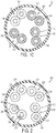
FIGS. 1A - 1C are each a cross sectional view of a cable according to a general disclosure; -
FIG. 2 is a cross sectional view of a cable according to a general disclosure; -
FIG. 3 is a cross sectional view of a cable according to an exemplary embodiment of the present invention; -
FIG. 4 is a cross sectional view of a cable according to another exemplary embodiment of the present invention; and -
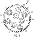
FIG. 5 is a cross sectional view of a cable according to a general disclosure. - Referring to
FIGS. 1A, 1B ,1C , and2-5 , the present disclosure relates to a cable construction that combines (1) one or more conductors that are insulated with a material that is zero halogen and also flame retardant with (2) one or more conductors that are insulated with a zero halogen material that is not flame retardant. The conductors may be twisted into pairs (e.g.FIG. 1A ) or may be individual conductors (FIG. 5 ). Such a cable construction is both halogen free and meets industry standards for flame suppression, particularly for riser (floor-to-floor) cables. Although this zero halogen concept would make a CMR rated riser cable more expensive, it has the benefit of an entirely zero halogen construction while still meeting industry burn test requirements. That is, by adding additional flame suppressants to the insulation material of the core cable construction by use of a highly flame retardant or viscosity-modified zero halogen pair or pairs, the likelihood of meeting UL's flame spread requirements (UL 1666) is increased. Moreover, the addition of flame suppressing material to the inner core of the cable allows use of a more, cost effective, flexible, zero halogen outer jacket to protect the cable. The cable of the present invention is designed to be used primarily as a transmission cable (solid or stranded); however, it may be used as any cable required to meet CMR UL1666 (NEC NFPA 70) flame test or CMR test requirements for cable safety ratings. - Referring to
FIG. 1A , acable 100 according to the general disclosure includes a plurality of pairs of conductors twisted together, for example, first, second, third and fourth pairs, 120, 122, 124, and 126, to form an inner core that is surrounded by ajacket 130. The conductors of eachpair insulation insulation pair FIG. 1A , the material of theinsulation 140 of at least onepair 120 may also be flame retardant. For example, theinsulation 140 may be a flame retardant polyolefin. Flame retardant polyolefins may include for example, polyethylene, polypropylene, ethylenepropylene copolymer, ethylene-vinyl acetate, ethylene-ethyl acrylate, ethylene-methyl acrylate, copolymers containing ethylene monomeric units and terpolymers containing ethylene monomeric units. Also, non-porous micro oxide particles, such as silicone dioxide particles (described in commonly assignedUS. application serial no. 13/044,974, filed March 10, 2011 , entitled Insulation With Micro Oxide Particles), may be added to a standard zero halogen material to provide the flame retardancy. Alternatively, the insulation may be a mixture of highly flame retardant or viscosity-modified zero halogen material and standard zero halogen material, such as polyolefin. The mixture may be, for example, 20% of the zero halogen flame retardant material and 80% of a standard non-flame retardant material like polyolefin. - The
insulation pairs jacket 130 also be formed of a zero halogen insulating material. The jacket material may be a standard (non-flame retardant) zero halogen material, a flame retardant zero halogen material, or a mixture of both. -
FIGS. 1B and1C illustrate other examples of the above combination.FIG. 1B shows that theinsulation pairs insulation pairs FIG. 1C shows that theinsulation pairs insulation 146 of the remainingpair 126 is a non-flame retardant zero halogen material. Although not illustrated, the cable construction of the general disclosure may be applied to any pair count of the cable core, e.g. two pair [1x1], three pair [2x1 or 1x2], four pair [3x1, 2x2, 1x3], six pair, etc. - Referring to
FIG. 2 , acable 200 according to the general disclosure is similar to the above disclosure except that only a portion of the conductor insulation is a zero halogen that is flame retardant material. Preferably, the portion of insulation is a highly flame retardant material, such as flame, viscosity modified group consisting of polyethylene, polypropylene, ethylene-propylene copolymer, ethylene-vinyl acetate, ethylene-ethyl acrylate, ethylene-methyl acrylate, copolymers containing ethylene monomeric units, terpolymers containing ethylene monomeric unit, or the like. Like the cable of the above disclosure thecable 200 has four conductor pairs 220, 222, 224, and 226 that form a core surrounded by ajacket 230. The conductors of eachpair insulation insulation 240 of at least oneconductor pair 220 has a portion that is a flame retardant zero halogen material. For example, that portion may be alongitudinal strip 250, as seen inFIG. 2 . The remaining material of theinsulation 240 may be a standard non-flame retardant zero halogen material. The portion orstrip 250 may be added to any of theinsulation strip 250 of flame retardant material to one or more pairs of thecable 200, thecable 200 remains halogen free while also providing flame suppression to meet industry requirements. Like thejacket 130 of the above disclosure thejacket 230 is also preferably made of a zero halogen material that may be either flame retardant or not, or a mixture of both. - Referring to
FIG. 3 , acable 300 according to the present invention provides a dual layer of insulation for at least one conductor pair where the outer layer is a flame retardant material. In particular, the insulation 340 and 342 of the conductor pairs 320 and 322 has aninner layer 360 and anouter layer 370. Theinner layer 360 of the insulation is a standard zero halogen material that is not flame retardant. Theouter layer 370 surrounds theinner layer 360 and is a flame retardant zero halogen material, like the material described above with respect to the first embodiment. Theinsulation jacket 330 surrounding the conductor pairs is preferably formed of a zero halogen material that may be either flame retardant or not, or a mixture of both. Thejacket 330 may also have two or more layers. For example, an outer layer of the jacket could be formed of a highly flame retardant zero halogen material and/or outer layer silicon dioxide an inner layer may be a micro oxide particle modified insulation. - As seen in
FIG. 4 , theinner layer 360 may be foamed. Theouter layer 370 may also be foamed. Moreover, the insulation of the conductor pairs of any of the embodiments described herein may be entirely or partially foamed. - Referring to
FIG. 5 , acable 500 according to the general disclosure includesindividual conductors 510 instead of pairs of conductors. Eachconductor 510 is insulated with zero halogen material. And at least one of those conductors is insulated with a flame retardant zero halogen material in the same manner as described above with respect to the above disclosures. For example, the insulation for one ormore conductors 510 may be one of a solid zero halogen flame retardant material (insulation 520) similar to the first disclosure; may have only a portion or strip of flame retardant material (insulation 522) similar to the second disclosure; may be dual layers with at least the outer layer being flame retardant (insulation 524) similar to the invention; may have a portion or layer that is foamed (insulation 526) similar to the fourth disclosure; or may be entirely foamed (insulation 528). Any number of theconductors 510 may be insulated with a flame retardant zero halogen material as described above in any combination. As with the other disclosures, the insulation for the remainingconductors 510 is preferably standard zero halogen material that is not flame retardant. - Cable accessories (not shown), such as separators, crosswebs, shields, screens, foils, barriers and the like, may also be used with the cables of the present invention. Like the jackets of the above embodiments, the cable accessories are preferably made of a zero halogen material that is not flame retardant, flame retardant, or a mixture of both.
Claims (8)
- A cable, comprising:
a cable core including:a plurality of insulated pairs of twisted conductors, each of said plurality of insulated pairs of twisted conductors comprising insulation,wherein said insulation of one or more primary pairs of twisted conductors of said plurality of insulated pairs of twisted conductors comprise an inner layer and an outer layer, said outer layer being formed of a zero halogen material that is flame retardant, said inner layer being formed of a zero halogen material that is not flame retardant, andsaid insulation of one or more secondary pairs of twisted conductors of said plurality of insulated pairs of twisted conductors consists of a zero halogen material that is not flame retardant. - The cable according to claim 1, further comprising
a jacket surrounding said plurality of insulated pairs of twisted conductors, said jacket being formed of a zero halogen material. - The cable according to claim 2, wherein
said zero halogen material of said jacket is a mixture of flame retardant material and non-flame retardant material. - The cable according to claim 1, wherein
said outer layer is formed of a flame retardant polyolefin. - The-cable according to claim 1, further comprising
a separator disposed between said plurality of insulated pairs of twisted conductors, said separator being formed of a zero halogen material. - The cable according to claim 1, wherein the zero halogen material in said outer layer comprises non-porous micro oxide particles that are silicone dioxide particles.
- The cable according to claim 1, wherein
said insulation of said secondary pairs of twisted conductors of said insulated pairs of twisted conductors consists of a non-flame retardant polyethylene. - The cable according to claim 1, wherein
said plurality of insulated pairs of twisted conductors includes two primary pairs of twisted conductors and two secondary pairs of twisted conductors.
Applications Claiming Priority (3)
| Application Number | Priority Date | Filing Date | Title |
|---|---|---|---|
| US37000210P | 2010-08-02 | 2010-08-02 | |
| US13/184,964 US20120024570A1 (en) | 2010-08-02 | 2011-07-18 | Zero halogen cable |
| PCT/US2011/044529 WO2012018522A2 (en) | 2010-08-02 | 2011-07-19 | Zero halogen cable |
Publications (3)
| Publication Number | Publication Date |
|---|---|
| EP2601657A2 EP2601657A2 (en) | 2013-06-12 |
| EP2601657A4 EP2601657A4 (en) | 2015-04-29 |
| EP2601657B1 true EP2601657B1 (en) | 2020-06-17 |
Family
ID=45525548
Family Applications (1)
| Application Number | Title | Priority Date | Filing Date |
|---|---|---|---|
| EP11814997.0A Active EP2601657B1 (en) | 2010-08-02 | 2011-07-19 | Zero halogen cable |
Country Status (9)
| Country | Link |
|---|---|
| US (3) | US20120024570A1 (en) |
| EP (1) | EP2601657B1 (en) |
| KR (1) | KR20130095747A (en) |
| AR (1) | AR082445A1 (en) |
| BR (1) | BR112013002555B1 (en) |
| CA (1) | CA2806875C (en) |
| DK (1) | DK2601657T3 (en) |
| ES (1) | ES2814874T3 (en) |
| WO (1) | WO2012018522A2 (en) |
Families Citing this family (2)
| Publication number | Priority date | Publication date | Assignee | Title |
|---|---|---|---|---|
| CN104810099A (en) * | 2015-04-01 | 2015-07-29 | 兴乐电缆有限公司 | Novel high-flexibility fireproof cable and manufacturing method thereof |
| CN107248428A (en) * | 2017-06-22 | 2017-10-13 | 安徽电缆股份有限公司 | Environment-friendly type power cable |
Citations (1)
| Publication number | Priority date | Publication date | Assignee | Title |
|---|---|---|---|---|
| US20040163839A1 (en) * | 2003-02-20 | 2004-08-26 | Scott Dillon | Plenum communication cables comprising polyolefin insulation |
Family Cites Families (16)
| Publication number | Priority date | Publication date | Assignee | Title |
|---|---|---|---|---|
| US3826762A (en) * | 1969-07-23 | 1974-07-30 | M & T Chemicals Inc | Non-burning polyurethane foam containing a non-porous filler,a halogen source,and a phosphorus-containing compound |
| US3928210A (en) * | 1972-01-17 | 1975-12-23 | Dyna Therm Corp | Fire protective composition for use with electrical cables |
| US5162609A (en) * | 1991-07-31 | 1992-11-10 | At&T Bell Laboratories | Fire-resistant cable for transmitting high frequency signals |
| US5253317A (en) * | 1991-11-21 | 1993-10-12 | Cooper Industries, Inc. | Non-halogenated plenum cable |
| US5597981A (en) * | 1994-11-09 | 1997-01-28 | Hitachi Cable, Ltd. | Unshielded twisted pair cable |
| JPH08222039A (en) * | 1995-02-13 | 1996-08-30 | Yazaki Corp | Flame resistant heat resistant wire |
| US5689090A (en) * | 1995-10-13 | 1997-11-18 | Lucent Technologies Inc. | Fire resistant non-halogen riser cable |
| US5763823A (en) * | 1996-01-12 | 1998-06-09 | Belden Wire & Cable Company | Patch cable for high-speed LAN applications |
| JPH09259639A (en) * | 1996-03-26 | 1997-10-03 | Hitachi Cable Ltd | Unshielded paired cable |
| US6064008A (en) * | 1997-02-12 | 2000-05-16 | Commscope, Inc. Of North Carolina | Conductor insulated with foamed fluoropolymer using chemical blowing agent |
| GB9930509D0 (en) * | 1999-12-24 | 2000-02-16 | Plastic Insulated Cables Ltd | Communications cable |
| US6687437B1 (en) * | 2000-06-05 | 2004-02-03 | Essex Group, Inc. | Hybrid data communications cable |
| TW594799B (en) * | 2001-06-01 | 2004-06-21 | Furukawa Electric Co Ltd | Multilayer insulated wire and transformer using the same |
| KR100716381B1 (en) * | 2006-02-15 | 2007-05-11 | 엘에스전선 주식회사 | Composition for manufacturing insulation for electric wire coating and electric wire manufactured using the same |
| JP4270237B2 (en) * | 2006-07-31 | 2009-05-27 | 日立電線株式会社 | Non-halogen flame retardant thermoplastic elastomer composition, method for producing the same, and electric wire / cable using the same |
| BRPI0823007B1 (en) * | 2008-08-05 | 2019-03-06 | Prysmian S.P.A. | FLAME RETARDANT CABLE AND FLAME RETARDANT COMPOSITION |
-
2011
- 2011-07-18 US US13/184,964 patent/US20120024570A1/en not_active Abandoned
- 2011-07-19 WO PCT/US2011/044529 patent/WO2012018522A2/en not_active Ceased
- 2011-07-19 CA CA2806875A patent/CA2806875C/en active Active
- 2011-07-19 BR BR112013002555-7A patent/BR112013002555B1/en active IP Right Grant
- 2011-07-19 ES ES11814997T patent/ES2814874T3/en active Active
- 2011-07-19 KR KR1020137005392A patent/KR20130095747A/en not_active Ceased
- 2011-07-19 EP EP11814997.0A patent/EP2601657B1/en active Active
- 2011-07-19 DK DK11814997.0T patent/DK2601657T3/en active
- 2011-08-02 AR ARP110102784A patent/AR082445A1/en active IP Right Grant
-
2013
- 2013-06-21 US US13/924,020 patent/US20130284491A1/en not_active Abandoned
- 2013-06-21 US US13/924,124 patent/US20130292155A1/en not_active Abandoned
Patent Citations (1)
| Publication number | Priority date | Publication date | Assignee | Title |
|---|---|---|---|---|
| US20040163839A1 (en) * | 2003-02-20 | 2004-08-26 | Scott Dillon | Plenum communication cables comprising polyolefin insulation |
Also Published As
| Publication number | Publication date |
|---|---|
| KR20130095747A (en) | 2013-08-28 |
| EP2601657A2 (en) | 2013-06-12 |
| US20120024570A1 (en) | 2012-02-02 |
| DK2601657T3 (en) | 2020-09-07 |
| WO2012018522A2 (en) | 2012-02-09 |
| WO2012018522A3 (en) | 2012-04-12 |
| CA2806875A1 (en) | 2012-02-09 |
| EP2601657A4 (en) | 2015-04-29 |
| ES2814874T3 (en) | 2021-03-29 |
| US20130284491A1 (en) | 2013-10-31 |
| CA2806875C (en) | 2016-11-15 |
| US20130292155A1 (en) | 2013-11-07 |
| BR112013002555A2 (en) | 2016-05-31 |
| AR082445A1 (en) | 2012-12-05 |
| BR112013002555B1 (en) | 2023-10-31 |
Similar Documents
| Publication | Publication Date | Title |
|---|---|---|
| US6812408B2 (en) | Multi-pair data cable with configurable core filling and pair separation | |
| US5744757A (en) | Plenum cable | |
| US20130161058A1 (en) | Cable with non-flammable barrier layer | |
| US9202610B2 (en) | Cable component with non-flammable material | |
| US20040050578A1 (en) | Communications cable | |
| US20080073105A1 (en) | Telecommunications cable | |
| ES2912661T3 (en) | Fire resistant data communication cable | |
| EP3257056B1 (en) | Fire resistant cable | |
| CA2806875C (en) | Zero halogen cable | |
| US7084348B2 (en) | Plenum communication cables comprising polyolefin insulation | |
| US10714232B1 (en) | Twisted pair communication cables with foamed PVDF jackets | |
| CA3068491C (en) | Flame resistant data cables and related methods | |
| JP5556373B2 (en) | cable | |
| JP6717073B2 (en) | Insulated wire | |
| JPH04206113A (en) | Radioactive resistant cable | |
| CA2196485A1 (en) | Telecommunications cable | |
| US20160379733A1 (en) | Lan cable with foamed polysulfone insulation |
Legal Events
| Date | Code | Title | Description |
|---|---|---|---|
| PUAI | Public reference made under article 153(3) epc to a published international application that has entered the european phase |
Free format text: ORIGINAL CODE: 0009012 |
|
| 17P | Request for examination filed |
Effective date: 20130304 |
|
| AK | Designated contracting states |
Kind code of ref document: A2 Designated state(s): AL AT BE BG CH CY CZ DE DK EE ES FI FR GB GR HR HU IE IS IT LI LT LU LV MC MK MT NL NO PL PT RO RS SE SI SK SM TR |
|
| RIN1 | Information on inventor provided before grant (corrected) |
Inventor name: ALBRINCK, ALICE C. Inventor name: GOULD, ROB S. Inventor name: MCLINN, MATTHEW S. Inventor name: MILLER, SHAUN Inventor name: CHAMBERLAIN, RICHARD Inventor name: BROWN, SCOTT M. |
|
| DAX | Request for extension of the european patent (deleted) | ||
| A4 | Supplementary search report drawn up and despatched |
Effective date: 20150401 |
|
| RIC1 | Information provided on ipc code assigned before grant |
Ipc: H01B 7/29 20060101AFI20150326BHEP Ipc: H01B 11/02 20060101ALI20150326BHEP |
|
| STAA | Information on the status of an ep patent application or granted ep patent |
Free format text: STATUS: EXAMINATION IS IN PROGRESS |
|
| 17Q | First examination report despatched |
Effective date: 20171010 |
|
| GRAP | Despatch of communication of intention to grant a patent |
Free format text: ORIGINAL CODE: EPIDOSNIGR1 |
|
| STAA | Information on the status of an ep patent application or granted ep patent |
Free format text: STATUS: GRANT OF PATENT IS INTENDED |
|
| INTG | Intention to grant announced |
Effective date: 20200113 |
|
| GRAS | Grant fee paid |
Free format text: ORIGINAL CODE: EPIDOSNIGR3 |
|
| GRAA | (expected) grant |
Free format text: ORIGINAL CODE: 0009210 |
|
| STAA | Information on the status of an ep patent application or granted ep patent |
Free format text: STATUS: THE PATENT HAS BEEN GRANTED |
|
| AK | Designated contracting states |
Kind code of ref document: B1 Designated state(s): AL AT BE BG CH CY CZ DE DK EE ES FI FR GB GR HR HU IE IS IT LI LT LU LV MC MK MT NL NO PL PT RO RS SE SI SK SM TR |
|
| REG | Reference to a national code |
Ref country code: GB Ref legal event code: FG4D |
|
| REG | Reference to a national code |
Ref country code: CH Ref legal event code: EP |
|
| REG | Reference to a national code |
Ref country code: IE Ref legal event code: FG4D |
|
| REG | Reference to a national code |
Ref country code: DE Ref legal event code: R096 Ref document number: 602011067380 Country of ref document: DE |
|
| REG | Reference to a national code |
Ref country code: AT Ref legal event code: REF Ref document number: 1282327 Country of ref document: AT Kind code of ref document: T Effective date: 20200715 |
|
| REG | Reference to a national code |
Ref country code: DK Ref legal event code: T3 Effective date: 20200831 |
|
| REG | Reference to a national code |
Ref country code: NL Ref legal event code: FP |
|
| REG | Reference to a national code |
Ref country code: FI Ref legal event code: FGE |
|
| REG | Reference to a national code |
Ref country code: CH Ref legal event code: NV Representative=s name: FIAMMENGHI-FIAMMENGHI, CH |
|
| REG | Reference to a national code |
Ref country code: SE Ref legal event code: TRGR |
|
| PG25 | Lapsed in a contracting state [announced via postgrant information from national office to epo] |
Ref country code: NO Free format text: LAPSE BECAUSE OF FAILURE TO SUBMIT A TRANSLATION OF THE DESCRIPTION OR TO PAY THE FEE WITHIN THE PRESCRIBED TIME-LIMIT Effective date: 20200917 Ref country code: GR Free format text: LAPSE BECAUSE OF FAILURE TO SUBMIT A TRANSLATION OF THE DESCRIPTION OR TO PAY THE FEE WITHIN THE PRESCRIBED TIME-LIMIT Effective date: 20200918 Ref country code: LT Free format text: LAPSE BECAUSE OF FAILURE TO SUBMIT A TRANSLATION OF THE DESCRIPTION OR TO PAY THE FEE WITHIN THE PRESCRIBED TIME-LIMIT Effective date: 20200617 |
|
| REG | Reference to a national code |
Ref country code: LT Ref legal event code: MG4D |
|
| PG25 | Lapsed in a contracting state [announced via postgrant information from national office to epo] |
Ref country code: LV Free format text: LAPSE BECAUSE OF FAILURE TO SUBMIT A TRANSLATION OF THE DESCRIPTION OR TO PAY THE FEE WITHIN THE PRESCRIBED TIME-LIMIT Effective date: 20200617 Ref country code: HR Free format text: LAPSE BECAUSE OF FAILURE TO SUBMIT A TRANSLATION OF THE DESCRIPTION OR TO PAY THE FEE WITHIN THE PRESCRIBED TIME-LIMIT Effective date: 20200617 Ref country code: RS Free format text: LAPSE BECAUSE OF FAILURE TO SUBMIT A TRANSLATION OF THE DESCRIPTION OR TO PAY THE FEE WITHIN THE PRESCRIBED TIME-LIMIT Effective date: 20200617 Ref country code: BG Free format text: LAPSE BECAUSE OF FAILURE TO SUBMIT A TRANSLATION OF THE DESCRIPTION OR TO PAY THE FEE WITHIN THE PRESCRIBED TIME-LIMIT Effective date: 20200917 |
|
| PG25 | Lapsed in a contracting state [announced via postgrant information from national office to epo] |
Ref country code: AL Free format text: LAPSE BECAUSE OF FAILURE TO SUBMIT A TRANSLATION OF THE DESCRIPTION OR TO PAY THE FEE WITHIN THE PRESCRIBED TIME-LIMIT Effective date: 20200617 |
|
| PG25 | Lapsed in a contracting state [announced via postgrant information from national office to epo] |
Ref country code: CZ Free format text: LAPSE BECAUSE OF FAILURE TO SUBMIT A TRANSLATION OF THE DESCRIPTION OR TO PAY THE FEE WITHIN THE PRESCRIBED TIME-LIMIT Effective date: 20200617 Ref country code: RO Free format text: LAPSE BECAUSE OF FAILURE TO SUBMIT A TRANSLATION OF THE DESCRIPTION OR TO PAY THE FEE WITHIN THE PRESCRIBED TIME-LIMIT Effective date: 20200617 Ref country code: SM Free format text: LAPSE BECAUSE OF FAILURE TO SUBMIT A TRANSLATION OF THE DESCRIPTION OR TO PAY THE FEE WITHIN THE PRESCRIBED TIME-LIMIT Effective date: 20200617 Ref country code: EE Free format text: LAPSE BECAUSE OF FAILURE TO SUBMIT A TRANSLATION OF THE DESCRIPTION OR TO PAY THE FEE WITHIN THE PRESCRIBED TIME-LIMIT Effective date: 20200617 Ref country code: PT Free format text: LAPSE BECAUSE OF FAILURE TO SUBMIT A TRANSLATION OF THE DESCRIPTION OR TO PAY THE FEE WITHIN THE PRESCRIBED TIME-LIMIT Effective date: 20201019 |
|
| PG25 | Lapsed in a contracting state [announced via postgrant information from national office to epo] |
Ref country code: SK Free format text: LAPSE BECAUSE OF FAILURE TO SUBMIT A TRANSLATION OF THE DESCRIPTION OR TO PAY THE FEE WITHIN THE PRESCRIBED TIME-LIMIT Effective date: 20200617 Ref country code: PL Free format text: LAPSE BECAUSE OF FAILURE TO SUBMIT A TRANSLATION OF THE DESCRIPTION OR TO PAY THE FEE WITHIN THE PRESCRIBED TIME-LIMIT Effective date: 20200617 Ref country code: IS Free format text: LAPSE BECAUSE OF FAILURE TO SUBMIT A TRANSLATION OF THE DESCRIPTION OR TO PAY THE FEE WITHIN THE PRESCRIBED TIME-LIMIT Effective date: 20201017 |
|
| REG | Reference to a national code |
Ref country code: DE Ref legal event code: R097 Ref document number: 602011067380 Country of ref document: DE |
|
| REG | Reference to a national code |
Ref country code: ES Ref legal event code: FG2A Ref document number: 2814874 Country of ref document: ES Kind code of ref document: T3 Effective date: 20210329 |
|
| PG25 | Lapsed in a contracting state [announced via postgrant information from national office to epo] |
Ref country code: MC Free format text: LAPSE BECAUSE OF FAILURE TO SUBMIT A TRANSLATION OF THE DESCRIPTION OR TO PAY THE FEE WITHIN THE PRESCRIBED TIME-LIMIT Effective date: 20200617 |
|
| PLBE | No opposition filed within time limit |
Free format text: ORIGINAL CODE: 0009261 |
|
| STAA | Information on the status of an ep patent application or granted ep patent |
Free format text: STATUS: NO OPPOSITION FILED WITHIN TIME LIMIT |
|
| REG | Reference to a national code |
Ref country code: BE Ref legal event code: MM Effective date: 20200731 |
|
| PG25 | Lapsed in a contracting state [announced via postgrant information from national office to epo] |
Ref country code: LU Free format text: LAPSE BECAUSE OF NON-PAYMENT OF DUE FEES Effective date: 20200719 |
|
| 26N | No opposition filed |
Effective date: 20210318 |
|
| PG25 | Lapsed in a contracting state [announced via postgrant information from national office to epo] |
Ref country code: BE Free format text: LAPSE BECAUSE OF NON-PAYMENT OF DUE FEES Effective date: 20200731 Ref country code: SI Free format text: LAPSE BECAUSE OF FAILURE TO SUBMIT A TRANSLATION OF THE DESCRIPTION OR TO PAY THE FEE WITHIN THE PRESCRIBED TIME-LIMIT Effective date: 20200617 |
|
| PG25 | Lapsed in a contracting state [announced via postgrant information from national office to epo] |
Ref country code: IE Free format text: LAPSE BECAUSE OF NON-PAYMENT OF DUE FEES Effective date: 20200719 |
|
| PG25 | Lapsed in a contracting state [announced via postgrant information from national office to epo] |
Ref country code: TR Free format text: LAPSE BECAUSE OF FAILURE TO SUBMIT A TRANSLATION OF THE DESCRIPTION OR TO PAY THE FEE WITHIN THE PRESCRIBED TIME-LIMIT Effective date: 20200617 Ref country code: MT Free format text: LAPSE BECAUSE OF FAILURE TO SUBMIT A TRANSLATION OF THE DESCRIPTION OR TO PAY THE FEE WITHIN THE PRESCRIBED TIME-LIMIT Effective date: 20200617 Ref country code: CY Free format text: LAPSE BECAUSE OF FAILURE TO SUBMIT A TRANSLATION OF THE DESCRIPTION OR TO PAY THE FEE WITHIN THE PRESCRIBED TIME-LIMIT Effective date: 20200617 |
|
| PG25 | Lapsed in a contracting state [announced via postgrant information from national office to epo] |
Ref country code: MK Free format text: LAPSE BECAUSE OF FAILURE TO SUBMIT A TRANSLATION OF THE DESCRIPTION OR TO PAY THE FEE WITHIN THE PRESCRIBED TIME-LIMIT Effective date: 20200617 |
|
| REG | Reference to a national code |
Ref country code: AT Ref legal event code: UEP Ref document number: 1282327 Country of ref document: AT Kind code of ref document: T Effective date: 20200617 |
|
| PGFP | Annual fee paid to national office [announced via postgrant information from national office to epo] |
Ref country code: NL Payment date: 20250726 Year of fee payment: 15 |
|
| PGFP | Annual fee paid to national office [announced via postgrant information from national office to epo] |
Ref country code: ES Payment date: 20250801 Year of fee payment: 15 Ref country code: FI Payment date: 20250725 Year of fee payment: 15 |
|
| PGFP | Annual fee paid to national office [announced via postgrant information from national office to epo] |
Ref country code: DK Payment date: 20250725 Year of fee payment: 15 Ref country code: DE Payment date: 20250729 Year of fee payment: 15 |
|
| PGFP | Annual fee paid to national office [announced via postgrant information from national office to epo] |
Ref country code: IT Payment date: 20250721 Year of fee payment: 15 |
|
| PGFP | Annual fee paid to national office [announced via postgrant information from national office to epo] |
Ref country code: GB Payment date: 20250728 Year of fee payment: 15 |
|
| PGFP | Annual fee paid to national office [announced via postgrant information from national office to epo] |
Ref country code: AT Payment date: 20250702 Year of fee payment: 15 Ref country code: FR Payment date: 20250725 Year of fee payment: 15 |
|
| PGFP | Annual fee paid to national office [announced via postgrant information from national office to epo] |
Ref country code: SE Payment date: 20250727 Year of fee payment: 15 Ref country code: CH Payment date: 20250801 Year of fee payment: 15 |