EP2601508B1 - Device and method for applying a force to a planar surface and for testing its structural integrity - Google Patents
Device and method for applying a force to a planar surface and for testing its structural integrity Download PDFInfo
- Publication number
- EP2601508B1 EP2601508B1 EP10747131.0A EP10747131A EP2601508B1 EP 2601508 B1 EP2601508 B1 EP 2601508B1 EP 10747131 A EP10747131 A EP 10747131A EP 2601508 B1 EP2601508 B1 EP 2601508B1
- Authority
- EP
- European Patent Office
- Prior art keywords
- planar surface
- force
- membrane
- tub
- bottom wall
- Prior art date
- Legal status (The legal status is an assumption and is not a legal conclusion. Google has not performed a legal analysis and makes no representation as to the accuracy of the status listed.)
- Active
Links
Images



Classifications
-
- G—PHYSICS
- G01—MEASURING; TESTING
- G01N—INVESTIGATING OR ANALYSING MATERIALS BY DETERMINING THEIR CHEMICAL OR PHYSICAL PROPERTIES
- G01N3/00—Investigating strength properties of solid materials by application of mechanical stress
- G01N3/32—Investigating strength properties of solid materials by application of mechanical stress by applying repeated or pulsating forces
- G01N3/36—Investigating strength properties of solid materials by application of mechanical stress by applying repeated or pulsating forces generated by pneumatic or hydraulic means
-
- G—PHYSICS
- G01—MEASURING; TESTING
- G01N—INVESTIGATING OR ANALYSING MATERIALS BY DETERMINING THEIR CHEMICAL OR PHYSICAL PROPERTIES
- G01N2203/00—Investigating strength properties of solid materials by application of mechanical stress
- G01N2203/0014—Type of force applied
- G01N2203/0016—Tensile or compressive
-
- G—PHYSICS
- G01—MEASURING; TESTING
- G01N—INVESTIGATING OR ANALYSING MATERIALS BY DETERMINING THEIR CHEMICAL OR PHYSICAL PROPERTIES
- G01N2203/00—Investigating strength properties of solid materials by application of mechanical stress
- G01N2203/003—Generation of the force
- G01N2203/0042—Pneumatic or hydraulic means
-
- G—PHYSICS
- G01—MEASURING; TESTING
- G01N—INVESTIGATING OR ANALYSING MATERIALS BY DETERMINING THEIR CHEMICAL OR PHYSICAL PROPERTIES
- G01N2203/00—Investigating strength properties of solid materials by application of mechanical stress
- G01N2203/003—Generation of the force
- G01N2203/0042—Pneumatic or hydraulic means
- G01N2203/0044—Pneumatic means
-
- G—PHYSICS
- G01—MEASURING; TESTING
- G01N—INVESTIGATING OR ANALYSING MATERIALS BY DETERMINING THEIR CHEMICAL OR PHYSICAL PROPERTIES
- G01N2203/00—Investigating strength properties of solid materials by application of mechanical stress
- G01N2203/02—Details not specific for a particular testing method
- G01N2203/026—Specifications of the specimen
- G01N2203/0262—Shape of the specimen
- G01N2203/0278—Thin specimens
- G01N2203/0282—Two dimensional, e.g. tapes, webs, sheets, strips, disks or membranes
Definitions
- the present disclosure relates to load generating devices and methods and, more particularly, to load generating devices and methods for applying a force to planar surfaces for testing the structural integrity of the planar surfaces and/or planar articles carrying the planar surfaces.
- Photovoltaic modules (also referred to as "PV modules”), e.g., solar panels, are conventionally mounted in locations that are most prone to solar exposure. These locations include, for example, rooftops, open land, etc. Unfortunately, such locations are also exposed to snow, ice, wind, or other static and/or dynamic loads generated by the surrounding environment. A heavy snowfall or ice accumulation, or too strong a wind, can cause structural damage to the PV modules. Therefore, in an effort to ensure that commercially available PV modules can withstand the elements, manufacturers often test the designs in accordance with standardized testing procedures. In one known testing procedure, a number of sandbags are stacked onto the planar solar-exposed surface of a PV module for a specified period of time, for example. At the end of the specified period of time, the PV module is inspected for signs of physical damage.
- Array Structure Fatigue Tester that is a machine designed to determine fatigue life of an array structure as an assembled unit, the machine simulates wind loading in both sustained and fatigue modes by substituting static air pressure for the velocity pressure generated by wind.
- the array structure to be tested is placed within a frame, a fan supplies the required pressure, simulating wind speed (the dominant loading mechanism) and corresponding environmental conditions. Sealed chambers above and below the array structures hold the simulated wind load, the machine is controlled by computer logic. Solenoid valves alternately permit air to inflate and exhaust the chambers to satisfy the correct load conditions.
- the test device comprises a test frame to permit mounting of the test item, two pressure panels, each including stiffeners, air duct, a plate with air distribution holes, rubber diaphragm (inflatable air bags), a vent valve and a pressure gauge to apply a uniform normal pressure to the front and back surfaces of the test modules, the device further comprises pressure control and timing equipment which provides regulated air to the pressure panels, provides control signals to alternately fill and vent the pressure panels, and includes a cycle counter.
- the device includes a tub, a cavity, a membrane, and at least one opening.
- the tub has a bottom wall and at least one sidewall extending upward from a perimeter of the bottom wall.
- the cavity is defined between the bottom wall and the at least one sidewall of the tub.
- the membrane is disposed within the cavity at a location proximate to the bottom wall of the tub, and has a perimeter edge that is fixed to the tub.
- the opening is formed in the tub and adapted to receive a pressurized fluid to fill a portion of the cavity that is disposed between the membrane and the bottom wall to displace at least a portion of the membrane away from the bottom wall to apply a force to the planar surface during operation of the device.
- a bed of media is disposed within the cavity on top of the membrane such that displacement of the membrane away from the bottom wall results in displacement of at least a portion of the bed of media away from the bottom wall and into engagement with the planar surface during operation of the device.
- the bed of media can include a plurality of balls.
- the bed of media can include three million plastic balls, each plastic ball having a diameter of approximately six millimeters.
- the membrane can include an elastomeric material.
- the device further includes at least one force sensor adapted to sense the force applied to the planar surface during operation of the device.
- the device includes a u-shaped bracket attached to the tub and suspending the at least one force sensor opposite the planar surface from the membrane, e.g., above the planar surface.
- the device can further include at least one pressurized fluid source connected to the at least one opening in the tub for delivering pressurized fluid to the cavity.
- the device can further include an electronic control unit communicatively coupled to the at least one force sensor and the pressurized fluid source for controlling and monitoring operation of the device.
- the electronic control unit can include a user interface for receiving user input and/or displaying output.
- the device can further include at least one adjustment panel horizontally disposed through the at least one sidewall of the tub and adapted to be adjusted to extend between the at least one sidewall and approximately a perimeter of the planar surface during operation of the device.
- the present invention provides a method for testing the structural integrity of a planar surface as defined in claim 9 as appended hereto. The method includes positioning a planar surface above a membrane disposed within a cavity of a tub, wherein the cavity is defined between a bottom wall and at least one sidewall of the tub. The method further includes positioning a planar surface onto a bed of media disposed within the cavity and supported by the membrane.
- the method further includes introducing a pressurized fluid into a portion of the cavity that is disposed between the bottom wall of the tub and the membrane.
- the method further includes displacing at least a portion of the membrane and the bed of media away from the bottom wall of the tub and into engagement with the planar surface with the pressurized fluid.
- the method further includes applying a force to the planar surface, the force being transferred through the membrane.
- applying a force to the planar surface can include applying a force of a predetermined magnitude for a predetermined duration.
- applying a force to the planar surface can include applying a force of uniform magnitude across the planar surface.
- displacing at least a portion of the bed of media can include displacing a plurality of plastic balls into engagement with the planar surface.
- introducing a pressurized fluid into a portion of the cavity can include delivering a pressurized gas into a portion of the cavity.
- the method further comprises detecting a magnitude of the force being applied to the planar surface with at least one force sensor.
- the method can further comprise controlling a duration of the force being applied to the planar surface.
- the method can further comprise inputting one or more of the following parameters into a user interface prior to introducing the pressurized fluid into the cavity: (a) a magnitude of the force to be applied to the planar surface; (b) a duration for which the force is to be applied to the planar surface; (c) a total number of cycles through which the force is to be applied the planar surface; and (d) a duration of any pause between cycles through which the force is to be applied to the planar surface.
- the device and method described herein are for generating a substantially uniform load, e.g., force, in a direction transverse to a two-dimensional plane for testing the structural integrity of a planar surface or a planar article such as a photovoltaic module (hereinafter "PV module").
- PV module photovoltaic module
- Such tests are aimed at determining the ability of a PV module to withstand static and/or dynamic loads generated from wind, ice, snow, etc., and can be performed in accordance with various standardized testing protocols such as UL 1703 section 41, IEC 616215 section 10.16, and IEC 61646 section 10.16.
- the device and method disclosed herein are generally designed for testing PV modules, they can also be used to test the structural integrity of other devices, or for any other foreseeable testing operation, manufacturing operation, or other function where a generally uniform load across a two-dimensional plane may be desired.
- Figs. 1 and 2 include a pair of schematic cross-sectional representations of a device 10 constructed in accordance with the present disclosure.
- the device 10 is shown occupying a passive state, e.g., non-operating state.
- the device 10 is shown occupying an active state, e.g., operating state.
- one example of the device 10 can generally include a steel tub 12, a membrane 14, a bed of media 16, at least one overhead U-shaped bracket 18, and a plurality of force sensors 20.
- one embodiment of the device 10 can include a plurality of adjustable panels 22 (only two panels 22a, 22c, of which are visible in Figs. 1 and 2 ), at least one fluid opening 30, and a puller bar 40, each of which will be described in further detail below.
- the tub 12 can generally resemble a box with an open top, for example, including a bottom wall 24, at least one sidewall 26 extending upward around a perimeter of the bottom wall 24, and a cavity 28 defined between the bottom wall 24 and the at least one sidewall 26.
- the at least one sidewall 26 of the tub 12 includes four sidewalls 26a-26d, as shown more particularly in Fig. 3 , such that the tub 12 has a generally square or rectangular shape when viewed from the top or bottom.
- the tub 12 can have generally any shape when viewed from the top and/or bottom.
- the membrane 14 includes a sheet of material disposed in the cavity 28 of the tub 12 proximate to the bottom wall 24, and mounted to the tub 12 to provide a generally fluid tight seal therebetween.
- the membrane 14 can be mounted adjacent to its perimeter edge to the bottom wall 24 of the tub 12 with L-brackets or some other means, for example.
- the membrane 14 can be mounted adjacent to its perimeter edge to each of the sidewalls 26a-26d of the tub 12. So configured, the membrane 16 can be mounted at a height in the tub 12 so as not to contact the bottom wall 24 of the tub 12 when the device occupies the passive state, as shown in Fig. 1 , for example.
- the membrane 14 can be constructed of a substantially inelastic material, an elastic material, a flexible material, an elastomeric material, or generally any other type of material suitable for the intended purpose.
- the bed of media 16 can include a plurality of balls 32 disposed in the tub 12 on top of the membrane 14.
- the plurality of balls 32 can include 3 million spherical plastic balls, each ball being approximately 6 millimeters in diameter. This is merely an example and other embodiments can include generally number and/or size of balls 32 suitable for the intended purpose.
- the bed of media 16 can include generally any type of media capable of serving the intended purpose.
- the bed of media 16 can include a plurality of objects having generally any shape, the objects being the same or different in shape, size, density, etc., or the bed of media 16 can include a fluid such as a liquid or a gas, or even a gel or other type of deformable mass.
- the device 10 could further include a second membrane (not shown) disposed opposite the bed of media 16 from the membrane 14, e.g., on top of the bed of media 16, such that the bed of media 16 is sandwiched between two membranes.
- a second membrane (not shown) disposed opposite the bed of media 16 from the membrane 14, e.g., on top of the bed of media 16, such that the bed of media 16 is sandwiched between two membranes.
- Two membranes could be especially useful in an embodiment where the bed of media 16 includes a bed of fluid, for example, for retaining the fluid in the tub 12 both during operation and when the device 10 is non-operational.
- the at least one overhead U-shaped bracket 18, as illustrated, carries the plurality of force sensors 20 such that the force sensors 20 are suspended above the bed of media 16 and the membrane 14 at a location opposite the bed of media 16 from the membrane 14.
- a planar article 36 which constitutes a PV module 34 in this example, is shown positioned in the device 10.
- the PV module 34 includes a photovoltaic panel 36 (hereinafter "PV panel") mounted to a pair of roof brackets 38, only one of which is visible in Figs. 1 and 2 .
- PV panel photovoltaic panel
- Each of the roof brackets 38 includes a generally straight member mounted to the backside of the PV panel 36 parallel to the other roof bracket 38.
- the PV module 34 is disposed in the tub 12 on top of the bed of media 16, and beneath the force sensors 20.
- the roof brackets 38 face upward and are aligned with the force sensors 20, and a front planar surface 42a of the PV panel 36 faces downward and is in contact with the bed of media 16. So configured, the PV module 34 depicted in Figs. 1 and 2 can be described as occupying an "upside-down" orientation.
- the PV module 34 could be turned over relative to the "upside-down" orientation to occupy a "right-side up” orientation.
- the front planar surface 42a of the PV panel 36 faces upward toward the force sensors 20 and the roof brackets 38 face downward and are in contact with the bed of media 16.
- the roof brackets 38 sink into, e.g., penetrate, the top surface of the bed of media 16 such that the bed of media 16 is in direct uniform contact with a rear planar surface 42b of the PV panel 36.
- the roof brackets 38 would still be aligned with the force sensors 20, but the force sensors 20 would instead be engaged by the PV panel 36.
- the front planar surface 42a of the PV panel 36 would be supported directly on the second membrane.
- the roof brackets 38 would necessarily deform the second membrane to enable the brackets 38 to sink into the bed of media 16. Such deformation of the membrane in the vicinity of the roof brackets 38 would preferably not limit the extent to which the bed of media 16 is capable of contacting the rear planar surface 42b PV panel 36 in a uniform manner.
- the device 10 of the disclosed embodiment can be equipped with the plurality of adjustable panels 22.
- the plurality of panels 22 includes four adjustable panels 22a-22d, one slidably disposed through each of the four sidewalls 26a-26d. As shown in Figs. 1 and 2 , the panels 22 are positioned between the membrane 14 and the bed of media 16 in the vertical direction and between a perimeter of the PV module 34 and the sidewalls 26a-26d of the tub 12 in the horizontal direction. This configuration can limit the expansion and/or deflection of the membrane 14 during operation to the region located within the perimeter boundaries of the PV module 34.
- a pneumatic line (not shown in Figs. 1 and 2 ) is connected to the fluid opening 30 disposed in the bottom wall 24 of the tub 12 and a pressurized gas is introduced into a portion 28a of the cavity 28 that is disposed between the membrane 14 and the bottom wall 24.
- gas is introduced at a pressure in the range of approximately 20 mbar to approximately 200 mbar.
- the present embodiment of the tub 12 includes only a single opening 30, alternative embodiments can have a plurality of openings 30 spaced about the bottom wall 24, each being connected to its own pneumatic line. Such a configuration can increase the uniformity of the introduction of gas to the cavity.
- the pressurized gas causes at least the portion of the membrane 14 that is located between the adjustable panels 22a-22d to displace upwardly away from the bottom wall 24, as shown Fig. 2 .
- displacement of the membrane 14 can result in the membrane 14 resiliently deforming, for example, by stretching similar to a balloon under the pressure of the gas delivered to the portion 28a of the cavity 28 of the tub 12.
- displacement of the membrane 14 upward causes the membrane 14 to displace at least a portion of the bed of media 16 upwardly away from the bottom wall 24 and into forceful engagement with 42a the PV panel 36 of the PV module 34 and, in the depicted embodiment, the front planar surface 42a of the PV panel 36.
- This force displaces the PV module 34 upwardly away from the bottom wall 24 and into engagement with the force sensors 20 carried by the overhead U-shaped brackets 18.
- the force sensors 20 are adapted to detect the magnitude of the force being applied to the PV module 34.
- the bed of media 16 applies a generally uniform force across the PV panel 36 of the PV module 34, and in the depicted embodiment, across the front planar surface 42a of the PV panel 36.
- This uniform application of force is achieved because the bed of media 16 acts similar to a fluid in that in the disclosed embodiment, the three million plastic balls 32 move relative to each other to uniformly distribute the load applied by the membrane 14 through the balls 32 and onto the PV panel 36. Actual fluids and other types of media can operate similarly.
- Fig. 3 depicts a specific construction of some of the components of one embodiment of the load generating device 10 of the present disclosure.
- the steel tub 12 includes a frame 44 constructed of steel tubes and including legs 44a supporting the device on a floor, for example.
- the bottom wall 24 and the sidewalls 26a-26d are each constructed of a sheet metal material and can be welded or otherwise fixed to the frame 44.
- the membrane 14 is fixed into the tub 12, as shown generally in Figs. 1 and 2 , with a plurality of angle fixtures 46, which are shown in Fig. 3 .
- Each angle fixture 46 can include an elongate metal member having an L-shaped cross-section, and which can be secured to the frame 44 of the tub 12 or directly to the bottom wall 24 or sidewalls 26a-26d of the tub 12 with screws, welding, rivets, or any other means, for example.
- each of the overhead U-shaped brackets 18 can be mounted with screws 48 to the topmost steel tube 50 of the frame 44.
- the topmost tube 50 can include a plurality of different sets of holes for receiving the screws 48, such that the position of the overhead U-shaped brackets 18 can be adjusted to accommodate PV modules 34 having roof brackets 38 of different spacing.
- the device 10 can include adjustable panels 22 for focusing the deflection of the membrane 14 to the area disposed between the perimeter boundaries of the PV module 34.
- the adjustable panels 22 can be adjusted by sliding horizontally through elongated openings (not shown) in the sidewalls 26a-26d of the tub 12.
- the adjustable panels 22 include guide pins 56 disposed on opposing sides that are adapted to be slidably disposed in corresponding guide brackets 58 mounted on the outside of the tub 12, only some of which can be seen in Fig. 3 . This sliding arrangement enables the position of the panels 22 to be adjusted in and out of the tub 12, thereby being adjustable to accommodate PV modules 34 of different dimensions.
- a set screw (not shown) can be utilized to fix the position of each of the adjustment panels 22 prior to operating the device 12.
- one set screw can be threaded through each of the guide brackets 58 to frictionally engage the corresponding guide pin 56, thereby locking the guide pins 56 and panels 22 in position.
- the device 10 of the presently disclosed embodiment can include the puller bar 40.
- the puller bar 40 constitutes an elongated bar adapted to be slidably mounted in the tub 12 at a height that corresponds to a top surface of the bed of media 16, as shown in Figs. 1 and 2 . So configured, after a loading operation is completed and the PV module 34 is removed from the tub 12, a technician can slide the puller bar 40 across the tub 12 to level the bed of media 16 in preparation for the next loading operation.
- the device 10 can further be equipped with a vibrating mechanism such as a shaker table (not shown), for example, which can be activated when the PV module 34 is loaded right-side up, for example (i.e., when the roof brackets 38 are disposed in contact with the bed of media 16).
- a vibrating mechanism such as a shaker table (not shown), for example, which can be activated when the PV module 34 is loaded right-side up, for example (i.e., when the roof brackets 38 are disposed in contact with the bed of media 16).
- the vibrating mechanism can be activated to vibrate the bed of media 16 and/or the PV module 34 to obtain good displacement of the plastic balls 32 around the roof brackets 38 such that the balls 32 evenly distribute and uniformly contact the rear planar surface of the PV panel 36.
- the device 10 of the present disclosure is for testing the structural integrity of PV modules 34.
- the device 10 can be incorporated into a system 100, as depicted in Fig. 4 , for example.
- the system 100 of Fig. 4 includes the device 10, an electronic control unit 102, and a pressure control unit 104.
- the electronic control unit 102 can include a personal computer (hereinafter "PC") 106, an A/D unit 108, and a relay unit 110.
- the PC 106 can include a user interface 111 including, for example, an input device 112 such as a keyboard or touchscreen for enabling a user to input data into the PC 106, and an output device 114 such as a monitor, printer, speaker, or other device for conveying information to the user.
- an input device 112 such as a keyboard or touchscreen for enabling a user to input data into the PC 106
- an output device 114 such as a monitor, printer, speaker, or other device for conveying information to the user.
- the PC 106 can include a processor, a RAM memory, a ROM memory, and/or any other component typically associated with a conventional computing device.
- the pressure control unit 104 includes at least one pressurized gas source 130 and at least one pressure control valve 132, for example.
- the A/D unit 108 includes a conventional analog/digital converter.
- the relay unit 110 acts as a conventional switch for controlling the flow of power to the load generating device 10 and the pressure control unit 104 in response to appropriate direction received from the PC 106.
- the PC 106 is communicatively coupled to the A/D unit 108 and the relay unit 110 via communication lines 116, 118, respectively.
- the A/D unit 108 is communicatively coupled to the pressure control unit 104 via a communication line 120, and to the load generating device 10 via a communication line 122.
- the relay unit 110 can be communicatively coupled to the load generating device 10 via a power line 124.
- the relay unit 110 is communicatively coupled to the pressure control unit 104 via a power line 126.
- the pressure control unit 104 includes a pneumatic line 128 connected to the load generating device 10 and, more particularly, to the fluid opening 30 in the bottom wall 24 of the tub 12 of the device 10, as discussed above with reference to Figs. 1 and 2 .
- a user can enter data related to the forthcoming testing procedure into the PC 106 via the user interface 111.
- the data may include, for example, information indicative of the PV module 34 to be tested, information indicative of the test procedure to be performed, information indicative of the type and/or number of reports to be generated at the completion of the testing procedure, and/or any other foreseeable data.
- Information indicative of the PV module 34 can include the dimensions of the PV module 34, the weight of the PV module 34, the material or materials of which the PV module 34 is constructed, the manufacturer of the PV module 34, the model number and/or serial number of the PV module 34, etc.
- Information indicative of the test procedure can include, for example, a magnitude of a target force to be applied to the the PV module 34, a duration for which the target force is to be applied to the PV module 34, a total number of cycles through which the target force is to be applied to the PV module 34, a duration of any pause between cycles through which the target force is to be applied to the PV module 34, a pressure at which gas is delivered to the device 10 during operation, a velocity at which gas is delivered to the device 10 during operation, etc.
- the PV module 34 can be positioned upside-down into the tub 12 of the device 10 such that its front planar surface 42a is disposed in contact with the bed of media 16, as described above with reference to Fig. 1 .
- block 202 can include positioning the PV module 34 into the tub 12 right-side up such that the roof brackets 38 and the rear planar surface 42b of the PV module 34 are disposed in contact with the bed of media 16.
- block 202 can further include activating a vibrating mechanism, as discussed above, to evenly distribute the bed of media 16 around the roof brackets 38 and into contact with the rear planar surface of the PV panel 36.
- block 202 can include the PC 106 sending a signal to the relay unit 110 over communication line 118 instructing the relay unit 110 to activate the vibrating mechanism by energizing power line 124 for a specified duration. Additionally, block 202 can include any desired adjustment of the position of the adjustable panels 22a-22d discussed above.
- the PC 106 can initiate the testing procedure at block 204.
- the PC 106 sends a digital signal to the A/D unit 108 over communication line 116 indicative of the initial force to be applied to the PV module 34, and sends a separate digital signal to the relay unit 110 over communication line 118 instructing the relay unit 110 to switch open the supply of power to the pressure control unit 104.
- the A/D unit 108 converts the signal received from the PC 106 to an analog signal and transmits the analog signal to the pressure control unit 104 over communication line 120.
- the energized pressure control unit 110 opens the control valve 132 to an extent that is based on the analog signal received from the A/D unit 108.
- pressurized gas flows from the pressurized gas source 130, through the pneumatic line 128, and into the portion 28a of the cavity 28 of the tub 12, as indicated at block 210 and described above with reference to Figs. 1 and 2 .
- the pressurized gas causes the membrane 14 to displace upwardly away from the bottom wall 24 of the tub 12.
- the displacement of the membrane 14, causes at least a portion of the bed of media 16 to displace upwardly away from the bottom wall 24 of the tub 12, as indicated at block 214, and apply a force to the PV module 34, as indicated at block 216.
- the force applied to the PV module 34 is uniform across its two-dimensional surface and it displaces the PV module 34 into engagement with the force sensors 20 carried by the upper U-shaped brackets 18.
- the brackets 18 detect the magnitude of the force being applied to the PV module 34, as indicated at block 218.
- each of the force sensors 20 transmit the detected forces to the A/D unit 108, or alternatively, the A/D unit 108 extracts the detected forces from each of the force sensors 20.
- the A/D unit 108 converts the detected forces to one or more digital signals and transmits the signal(s) to the PC 106.
- the PC 106 determines whether the detected forces match the target force for the particular test procedure being conducted. If the forces do not match the target force, the PC 106 sends an adjusted digital signal to the A/D unit 108 at block 226, which then sends an adjusted analog signal to the pressure control unit 104 to adjust the opening of the control valve 132, which in turn, adjusts the amount of pressure being supplied to the tub 12 via pneumatic line 128. The process then returns to block 218.
- the PC 106 waits for a specified duration, as indicated at block 228.
- the specified duration corresponds to a duration dictated by the particular testing procedure being conducted, for example, or by the data input to the PC 106 at block 200 discussed above.
- the PC 106 sends a digital signal to the A/D unit 108 indicative of a close command, in response to which, the A/D unit 108 sends an analog signal to the pressure control unit 104 to close the pressure control valve 132 and stop supplying pressurized gas to the tub 12, as indicated at block 230.
- any pressure built up in the tub 12 can be automatically vented through an exhaust valve (not shown) connected to the tub 12, for example, or through an exhaust valve associated with the pressure control valve 132 itself.
- an exhaust valve not shown
- the membrane 14 and bed of media 16 return to their passive state, shown in Fig. 1 .
- the testing procedure is complete, as indicated at block 234, and the PV module 34 can be removed from the device 10.
- the bed of media 16 Prior to loading a subsequent PV module 34 for testing, the bed of media 16 can be leveled, as indicated at block 236, through operation of the puller bar 40 discussed above.
- the load generating device 10 includes a vibrating mechanism
- the vibrating mechanism could also be used to level the bed of media 16 between testing operations.
- the PC 106 could send a signal to the relay unit 110 over communication line 118 instructing the relay unit 110 to activate the vibrating mechanism by energizing power line 124 for a specified duration to level the bed of media 16.
- the PC 106 waits for a designated pause duration, as indicated at block 238, prior to returning to block 206 to repeat the previously described process.
- subsequent loading cycles may apply a force to the PV module 34 that is the same as or different from the magnitude previously applied.
- subsequent loading cycles may apply a force to the PV module 34 for a duration that is the same as or different from the previous duration.
- the magnitude and duration of the force applied to the PV module 34 during each cycle of any testing procedure can be dictated and controlled by the electronic control unit 102 such that any give testing process is accurate and repeatable.
- the electronic control unit 102 of the present disclosure is advantageously capable of generating any number and/or style of reports related to the testing process including data, graphs, and analysis related to the magnitude and duration of the forces applied to the PV modules 34.
- reports could be generated on the display device 114 of the user interface 111 of the PC 106, saved to a memory, or printed in hard copy, for example.
- the load generating device 10 of the present invention includes a bed of media 16 disposed on top of the membrane 14, at least one alternative embodiment of the device 10, which is not part of the present invention, can be constructed without the bed of media 16.
- one alternative load generating device 10 can include all of the features of the device 10 described above with reference to Figs. 1-3 , but for the bed of media 16.
- the introduction of pressurized gas into the portion 28a of the cavity 28 disposed below the membrane 14 causes the membrane 14 to displace or deflect upward and into direct engagement with a planar surface of a planar article being tested, which in Fig. 6 constitutes a front planar surface 42a of a PV panel 36 of a PV module 34.
- the displacement of the membrane 14 forcefully engages the PV module 34 and forces the PV module 34 into engagement with the force sensors 20 in a manner generally similar to that described above with reference to Figs. 1-5 .
- the device depicted in Fig. 6 could easily by used in the system described with reference to Fig. 4 .
- the method described above with reference to Fig. 5 could easily be adapted to be performed using the device 10 depicted in Fig. 6 .
- loading the PV module 34 into the device 10 of Fig. 6 simply includes positioning the PV module 34 directly on the membrane 14, and any force applied to the membrane 14 by the pressurized gas introduced through the opening 30 in the tub 12, would be transferred directly to the PV module 34 without distribution through the bed of media 16.
- the present disclosure advantageously provides among other advantages (a) a device capable of generating a uniform force across a two-dimensional planar surface; (b) a device that has the ability to generate detailed test results such as the magnitude of the force applied to the PV module, the duration of the test, the force carried by the roof brackets at the specific locations of the force sensors, etc.; and (c) the device and method enable a very quick, efficient, automated, and repeatable test procedure.
Landscapes
- Physics & Mathematics (AREA)
- Health & Medical Sciences (AREA)
- Life Sciences & Earth Sciences (AREA)
- Chemical & Material Sciences (AREA)
- Analytical Chemistry (AREA)
- Biochemistry (AREA)
- General Health & Medical Sciences (AREA)
- General Physics & Mathematics (AREA)
- Immunology (AREA)
- Pathology (AREA)
- Force Measurement Appropriate To Specific Purposes (AREA)
- Investigating Strength Of Materials By Application Of Mechanical Stress (AREA)
- Vibration Prevention Devices (AREA)
- Lining Or Joining Of Plastics Or The Like (AREA)
Description
- The present disclosure relates to load generating devices and methods and, more particularly, to load generating devices and methods for applying a force to planar surfaces for testing the structural integrity of the planar surfaces and/or planar articles carrying the planar surfaces.
- Photovoltaic modules (also referred to as "PV modules"), e.g., solar panels, are conventionally mounted in locations that are most prone to solar exposure. These locations include, for example, rooftops, open land, etc. Unfortunately, such locations are also exposed to snow, ice, wind, or other static and/or dynamic loads generated by the surrounding environment. A heavy snowfall or ice accumulation, or too strong a wind, can cause structural damage to the PV modules. Therefore, in an effort to ensure that commercially available PV modules can withstand the elements, manufacturers often test the designs in accordance with standardized testing procedures. In one known testing procedure, a number of sandbags are stacked onto the planar solar-exposed surface of a PV module for a specified period of time, for example. At the end of the specified period of time, the PV module is inspected for signs of physical damage.
- S. C. Fairbanks and R.C. Cull in "THE ARRAY STRUCTURE FATIGUE TESTER: A METHOD OF FATIGUE TESTING STRUCTURAL UNITS", IEE Photovoltaic specialists conference, Las Vegas Nevada 21-25 October 1985 discloses an Array Structure Fatigue Tester, that is a machine designed to determine fatigue life of an array structure as an assembled unit, the machine simulates wind loading in both sustained and fatigue modes by substituting static air pressure for the velocity pressure generated by wind. The array structure to be tested is placed within a frame, a fan supplies the required pressure, simulating wind speed (the dominant loading mechanism) and corresponding environmental conditions. Sealed chambers above and below the array structures hold the simulated wind load, the machine is controlled by computer logic. Solenoid valves alternately permit air to inflate and exhaust the chambers to satisfy the correct load conditions.
- G. Nuss and R. De Blasio in "PERFORMANCE CRITERIA FOR PHOTOVOLTAIC ENERGY SYSTEMS" Volume II, pages 70-79 by Solar Energy Research Institute/ U.S. Department of Energy, July 1982, discloses a cyclic pressure load test device to determine the ability of a photovoltaic module design to withstand mechanical fatigue by cyclically applying specific levels of positive and negative pressure loads that reflect the normal wind, snow, and ice loading. The test device comprises a test frame to permit mounting of the test item, two pressure panels, each including stiffeners, air duct, a plate with air distribution holes, rubber diaphragm (inflatable air bags), a vent valve and a pressure gauge to apply a uniform normal pressure to the front and back surfaces of the test modules, the device further comprises pressure control and timing equipment which provides regulated air to the pressure panels, provides control signals to alternately fill and vent the pressure panels, and includes a cycle counter.
- One aspect of the present invention provides a device for testing the structural integrity of a planar surface as defined in claim 1 as appended hereto. The device includes a tub, a cavity, a membrane, and at least one opening. The tub has a bottom wall and at least one sidewall extending upward from a perimeter of the bottom wall. The cavity is defined between the bottom wall and the at least one sidewall of the tub. The membrane is disposed within the cavity at a location proximate to the bottom wall of the tub, and has a perimeter edge that is fixed to the tub. The opening is formed in the tub and adapted to receive a pressurized fluid to fill a portion of the cavity that is disposed between the membrane and the bottom wall to displace at least a portion of the membrane away from the bottom wall to apply a force to the planar surface during operation of the device.
- A bed of media is disposed within the cavity on top of the membrane such that displacement of the membrane away from the bottom wall results in displacement of at least a portion of the bed of media away from the bottom wall and into engagement with the planar surface during operation of the device.
- In one aspect, the bed of media can include a plurality of balls.
- In one aspect, the bed of media can include three million plastic balls, each plastic ball having a diameter of approximately six millimeters.
- In one aspect, the membrane can include an elastomeric material.
- The device further includes at least one force sensor adapted to sense the force applied to the planar surface during operation of the device.
- The device includes a u-shaped bracket attached to the tub and suspending the at least one force sensor opposite the planar surface from the membrane, e.g., above the planar surface.
- In one aspect, the device can further include at least one pressurized fluid source connected to the at least one opening in the tub for delivering pressurized fluid to the cavity.
- In one aspect, the device can further include an electronic control unit communicatively coupled to the at least one force sensor and the pressurized fluid source for controlling and monitoring operation of the device.
- In one aspect, the electronic control unit can include a user interface for receiving user input and/or displaying output.
- In one aspect, the device can further include at least one adjustment panel horizontally disposed through the at least one sidewall of the tub and adapted to be adjusted to extend between the at least one sidewall and approximately a perimeter of the planar surface during operation of the device. In another aspect, the present invention provides a method for testing the structural integrity of a planar surface as defined in claim 9 as appended hereto. The method includes positioning a planar surface above a membrane disposed within a cavity of a tub, wherein the cavity is defined between a bottom wall and at least one sidewall of the tub. The method further includes positioning a planar surface onto a bed of media disposed within the cavity and supported by the membrane. The method further includes introducing a pressurized fluid into a portion of the cavity that is disposed between the bottom wall of the tub and the membrane. The method further includes displacing at least a portion of the membrane and the bed of media away from the bottom wall of the tub and into engagement with the planar surface with the pressurized fluid. The method further includes applying a force to the planar surface, the force being transferred through the membrane..
- In some aspects, applying a force to the planar surface can include applying a force of a predetermined magnitude for a predetermined duration.
- In some aspects, applying a force to the planar surface can include applying a force of uniform magnitude across the planar surface.
- In some aspects, displacing at least a portion of the bed of media can include displacing a plurality of plastic balls into engagement with the planar surface.
- In some aspects, introducing a pressurized fluid into a portion of the cavity can include delivering a pressurized gas into a portion of the cavity.
- The method further comprises detecting a magnitude of the force being applied to the planar surface with at least one force sensor.
- In some aspects, the method can further comprise controlling a duration of the force being applied to the planar surface.
- In some aspects, the method can further comprise inputting one or more of the following parameters into a user interface prior to introducing the pressurized fluid into the cavity: (a) a magnitude of the force to be applied to the planar surface; (b) a duration for which the force is to be applied to the planar surface; (c) a total number of cycles through which the force is to be applied the planar surface; and (d) a duration of any pause between cycles through which the force is to be applied to the planar surface.
-
-
Fig. 1 is a schematic cross-sectional representation of one embodiment of a device for generating a load constructed in accordance with the present disclosure and shown occupying a passive state, e.g., non-operating state; -
Fig. 2 is a schematic cross-sectional representation of the device ofFig. 1 shown occupying an active state, e.g., operating state; -
Fig. 3 is an exploded perspective view of some of the components of the device ofFigs. 1 and 2 ; -
Fig. 4 is a block diagram of a system including the device ofFigs. 1-3 for applying a force to a planar surface; -
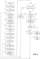
Fig. 5 is a flowchart of one method of the present disclosure for testing the structural integrity of a planar surface using the system ofFig. 4 ; and -
Fig. 6 is a cross-sectional representation of an alternative embodiment of a device for generating a load, which is not part of the present invention. - Although the following text sets forth a detailed description of one or more embodiments of the invention, it should be understood that the legal scope of the invention is defined by the words of the claims set forth at the end of this patent. The detailed description is to be construed as exemplary only and does not describe every possible embodiment of the invention since describing every possible embodiment would be impractical, if not impossible. Numerous alternative embodiments could be implemented, which would still fall within the scope of the claims defining the invention.
- It should also be understood that, unless a term is expressly defined in this patent using the sentence "As used herein, the term '_____' is hereby defined to mean..." or a similar sentence, there is no intent to limit the meaning of that term, either expressly or by implication, beyond its plain or ordinary meaning, and such term should not be interpreted to be limited in scope based on any statement made in any section of this patent (other than the language of the claims).
- In general, the device and method described herein are for generating a substantially uniform load, e.g., force, in a direction transverse to a two-dimensional plane for testing the structural integrity of a planar surface or a planar article such as a photovoltaic module (hereinafter "PV module"). Such tests are aimed at determining the ability of a PV module to withstand static and/or dynamic loads generated from wind, ice, snow, etc., and can be performed in accordance with various standardized testing protocols such as UL 1703 section 41, IEC 616215 section 10.16, and IEC 61646 section 10.16. While the device and method disclosed herein are generally designed for testing PV modules, they can also be used to test the structural integrity of other devices, or for any other foreseeable testing operation, manufacturing operation, or other function where a generally uniform load across a two-dimensional plane may be desired.
-
Figs. 1 and 2 include a pair of schematic cross-sectional representations of adevice 10 constructed in accordance with the present disclosure. InFig. 1 , thedevice 10 is shown occupying a passive state, e.g., non-operating state. InFig. 2 , thedevice 10 is shown occupying an active state, e.g., operating state. As illustrated inFigs. 1 and 2 , one example of thedevice 10 can generally include asteel tub 12, amembrane 14, a bed of media 16, at least one overheadU-shaped bracket 18, and a plurality offorce sensors 20. Additionally, as shown, one embodiment of thedevice 10 can include a plurality of adjustable panels 22 (only twopanels Figs. 1 and 2 ), at least onefluid opening 30, and apuller bar 40, each of which will be described in further detail below. - The
tub 12 can generally resemble a box with an open top, for example, including abottom wall 24, at least onesidewall 26 extending upward around a perimeter of thebottom wall 24, and acavity 28 defined between thebottom wall 24 and the at least onesidewall 26. In the disclosed embodiment, the at least onesidewall 26 of thetub 12 includes foursidewalls 26a-26d, as shown more particularly inFig. 3 , such that thetub 12 has a generally square or rectangular shape when viewed from the top or bottom. In other embodiments, thetub 12 can have generally any shape when viewed from the top and/or bottom. - The
membrane 14 includes a sheet of material disposed in thecavity 28 of thetub 12 proximate to thebottom wall 24, and mounted to thetub 12 to provide a generally fluid tight seal therebetween. In some embodiments, themembrane 14 can be mounted adjacent to its perimeter edge to thebottom wall 24 of thetub 12 with L-brackets or some other means, for example. In some other embodiments, themembrane 14 can be mounted adjacent to its perimeter edge to each of thesidewalls 26a-26d of thetub 12. So configured, the membrane 16 can be mounted at a height in thetub 12 so as not to contact thebottom wall 24 of thetub 12 when the device occupies the passive state, as shown inFig. 1 , for example. However, a certain amount of contact resulting from themembrane 12 sagging under the weight of the bed of media 16 can be acceptable. In one embodiment, themembrane 14 can be constructed of a substantially inelastic material, an elastic material, a flexible material, an elastomeric material, or generally any other type of material suitable for the intended purpose. - The bed of media 16 can include a plurality of balls 32 disposed in the
tub 12 on top of themembrane 14. In one example, the plurality of balls 32 can include 3 million spherical plastic balls, each ball being approximately 6 millimeters in diameter. This is merely an example and other embodiments can include generally number and/or size of balls 32 suitable for the intended purpose. In other embodiments, the bed of media 16 can include generally any type of media capable of serving the intended purpose. For example, the bed of media 16 can include a plurality of objects having generally any shape, the objects being the same or different in shape, size, density, etc., or the bed of media 16 can include a fluid such as a liquid or a gas, or even a gel or other type of deformable mass. In one alternative embodiment, thedevice 10 could further include a second membrane (not shown) disposed opposite the bed of media 16 from themembrane 14, e.g., on top of the bed of media 16, such that the bed of media 16 is sandwiched between two membranes. Two membranes could be especially useful in an embodiment where the bed of media 16 includes a bed of fluid, for example, for retaining the fluid in thetub 12 both during operation and when thedevice 10 is non-operational. - The at least one overhead
U-shaped bracket 18, as illustrated, carries the plurality offorce sensors 20 such that theforce sensors 20 are suspended above the bed of media 16 and themembrane 14 at a location opposite the bed of media 16 from themembrane 14. - Still referring to
Figs. 1 and 2 , aplanar article 36, which constitutes aPV module 34 in this example, is shown positioned in thedevice 10. In the disclosed embodiment, thePV module 34 includes a photovoltaic panel 36 (hereinafter "PV panel") mounted to a pair ofroof brackets 38, only one of which is visible inFigs. 1 and 2 . Each of theroof brackets 38 includes a generally straight member mounted to the backside of thePV panel 36 parallel to theother roof bracket 38. - As shown, the
PV module 34 is disposed in thetub 12 on top of the bed of media 16, and beneath theforce sensors 20. InFigs. 1 and 2 , theroof brackets 38 face upward and are aligned with theforce sensors 20, and a frontplanar surface 42a of thePV panel 36 faces downward and is in contact with the bed of media 16. So configured, thePV module 34 depicted inFigs. 1 and 2 can be described as occupying an "upside-down" orientation. - Depending on the specific testing process being conducted, however, the
PV module 34 could be turned over relative to the "upside-down" orientation to occupy a "right-side up" orientation. When disposed "right-side up," the frontplanar surface 42a of thePV panel 36 faces upward toward theforce sensors 20 and theroof brackets 38 face downward and are in contact with the bed of media 16. So configured, theroof brackets 38 sink into, e.g., penetrate, the top surface of the bed of media 16 such that the bed of media 16 is in direct uniform contact with a rearplanar surface 42b of thePV panel 36. In this "right-side up" orientation, theroof brackets 38 would still be aligned with theforce sensors 20, but theforce sensors 20 would instead be engaged by thePV panel 36. - In embodiments where the
device 10 includes a second membrane on top of the bed of media 16 and wherein thePV module 34 is loaded "upside-down" (as shown inFigs. 1 and 2 ), the frontplanar surface 42a of thePV panel 36 would be supported directly on the second membrane. In embodiments with a second membrane and where thePV module 34 is loaded "right-side up," theroof brackets 38 would necessarily deform the second membrane to enable thebrackets 38 to sink into the bed of media 16. Such deformation of the membrane in the vicinity of theroof brackets 38 would preferably not limit the extent to which the bed of media 16 is capable of contacting the rearplanar surface 42b PV panel 36 in a uniform manner. - Moreover, as mentioned above, the
device 10 of the disclosed embodiment can be equipped with the plurality of adjustable panels 22. The plurality of panels 22 includes fouradjustable panels 22a-22d, one slidably disposed through each of the foursidewalls 26a-26d. As shown inFigs. 1 and 2 , the panels 22 are positioned between themembrane 14 and the bed of media 16 in the vertical direction and between a perimeter of thePV module 34 and thesidewalls 26a-26d of thetub 12 in the horizontal direction. This configuration can limit the expansion and/or deflection of themembrane 14 during operation to the region located within the perimeter boundaries of thePV module 34. - For example, during operation of the
device 10, a pneumatic line (not shown inFigs. 1 and 2 ) is connected to thefluid opening 30 disposed in thebottom wall 24 of thetub 12 and a pressurized gas is introduced into aportion 28a of thecavity 28 that is disposed between themembrane 14 and thebottom wall 24. In some embodiments, gas is introduced at a pressure in the range of approximately 20 mbar to approximately 200 mbar. While the present embodiment of thetub 12 includes only asingle opening 30, alternative embodiments can have a plurality ofopenings 30 spaced about thebottom wall 24, each being connected to its own pneumatic line. Such a configuration can increase the uniformity of the introduction of gas to the cavity. In any event, the pressurized gas causes at least the portion of themembrane 14 that is located between theadjustable panels 22a-22d to displace upwardly away from thebottom wall 24, as shownFig. 2 . - In some embodiments, displacement of the
membrane 14 can result in themembrane 14 resiliently deforming, for example, by stretching similar to a balloon under the pressure of the gas delivered to theportion 28a of thecavity 28 of thetub 12. Regardless, displacement of themembrane 14 upward, in turn, causes themembrane 14 to displace at least a portion of the bed of media 16 upwardly away from thebottom wall 24 and into forceful engagement with 42a thePV panel 36 of thePV module 34 and, in the depicted embodiment, the frontplanar surface 42a of thePV panel 36. This force, in turn, displaces thePV module 34 upwardly away from thebottom wall 24 and into engagement with theforce sensors 20 carried by the overheadU-shaped brackets 18. Theforce sensors 20 are adapted to detect the magnitude of the force being applied to thePV module 34. As mentioned, the bed of media 16 applies a generally uniform force across thePV panel 36 of thePV module 34, and in the depicted embodiment, across the frontplanar surface 42a of thePV panel 36. This uniform application of force is achieved because the bed of media 16 acts similar to a fluid in that in the disclosed embodiment, the three million plastic balls 32 move relative to each other to uniformly distribute the load applied by themembrane 14 through the balls 32 and onto thePV panel 36. Actual fluids and other types of media can operate similarly. -
Fig. 3 depicts a specific construction of some of the components of one embodiment of theload generating device 10 of the present disclosure. For example, as shown inFig. 3 , in one embodiment, thesteel tub 12 includes aframe 44 constructed of steel tubes and includinglegs 44a supporting the device on a floor, for example. Thebottom wall 24 and thesidewalls 26a-26d are each constructed of a sheet metal material and can be welded or otherwise fixed to theframe 44. Themembrane 14 is fixed into thetub 12, as shown generally inFigs. 1 and 2 , with a plurality ofangle fixtures 46, which are shown inFig. 3 . Eachangle fixture 46 can include an elongate metal member having an L-shaped cross-section, and which can be secured to theframe 44 of thetub 12 or directly to thebottom wall 24 orsidewalls 26a-26d of thetub 12 with screws, welding, rivets, or any other means, for example. - As shown in
Fig. 3 , each of the overheadU-shaped brackets 18 can be mounted withscrews 48 to thetopmost steel tube 50 of theframe 44. Preferably, thetopmost tube 50 can include a plurality of different sets of holes for receiving thescrews 48, such that the position of the overheadU-shaped brackets 18 can be adjusted to accommodatePV modules 34 havingroof brackets 38 of different spacing. - As discussed above, the
device 10 can include adjustable panels 22 for focusing the deflection of themembrane 14 to the area disposed between the perimeter boundaries of thePV module 34. The adjustable panels 22 can be adjusted by sliding horizontally through elongated openings (not shown) in thesidewalls 26a-26d of thetub 12. As depicted, the adjustable panels 22 include guide pins 56 disposed on opposing sides that are adapted to be slidably disposed incorresponding guide brackets 58 mounted on the outside of thetub 12, only some of which can be seen inFig. 3 . This sliding arrangement enables the position of the panels 22 to be adjusted in and out of thetub 12, thereby being adjustable to accommodatePV modules 34 of different dimensions. Preferably, a set screw (not shown) can be utilized to fix the position of each of the adjustment panels 22 prior to operating thedevice 12. In one embodiment, one set screw can be threaded through each of theguide brackets 58 to frictionally engage thecorresponding guide pin 56, thereby locking the guide pins 56 and panels 22 in position. - Finally, as mentioned above with reference to
Figs. 1 and 2 , thedevice 10 of the presently disclosed embodiment can include thepuller bar 40. As shown inFig. 3 , thepuller bar 40 constitutes an elongated bar adapted to be slidably mounted in thetub 12 at a height that corresponds to a top surface of the bed of media 16, as shown inFigs. 1 and 2 . So configured, after a loading operation is completed and thePV module 34 is removed from thetub 12, a technician can slide thepuller bar 40 across thetub 12 to level the bed of media 16 in preparation for the next loading operation. Moreover, thedevice 10 can further be equipped with a vibrating mechanism such as a shaker table (not shown), for example, which can be activated when thePV module 34 is loaded right-side up, for example (i.e., when theroof brackets 38 are disposed in contact with the bed of media 16). With this orientation of thePV module 34, the vibrating mechanism can be activated to vibrate the bed of media 16 and/or thePV module 34 to obtain good displacement of the plastic balls 32 around theroof brackets 38 such that the balls 32 evenly distribute and uniformly contact the rear planar surface of thePV panel 36.. - As mentioned above, one application for the
device 10 of the present disclosure is for testing the structural integrity ofPV modules 34. To facilitate such tests, thedevice 10 can be incorporated into asystem 100, as depicted inFig. 4 , for example. Thesystem 100 ofFig. 4 includes thedevice 10, anelectronic control unit 102, and apressure control unit 104. - In the disclosed embodiment, the
electronic control unit 102 can include a personal computer (hereinafter "PC") 106, an A/D unit 108, and arelay unit 110. ThePC 106 can include auser interface 111 including, for example, aninput device 112 such as a keyboard or touchscreen for enabling a user to input data into thePC 106, and anoutput device 114 such as a monitor, printer, speaker, or other device for conveying information to the user. Additionally, although not illustrated inFig. 4 , it should be appreciated that thePC 106 can include a processor, a RAM memory, a ROM memory, and/or any other component typically associated with a conventional computing device. Thepressure control unit 104 includes at least onepressurized gas source 130 and at least onepressure control valve 132, for example. The A/D unit 108 includes a conventional analog/digital converter. Therelay unit 110 acts as a conventional switch for controlling the flow of power to theload generating device 10 and thepressure control unit 104 in response to appropriate direction received from thePC 106. - As illustrated in
Fig. 4 , thePC 106 is communicatively coupled to the A/D unit 108 and therelay unit 110 viacommunication lines D unit 108 is communicatively coupled to thepressure control unit 104 via acommunication line 120, and to theload generating device 10 via acommunication line 122. In an embodiment, wherein theload generating device 10 includes a vibrating mechanism for evenly distributing the plastic balls 32 of the bed of media 16 around theroof brackets 38 of thePV module 34, as discussed above,, therelay unit 110 can be communicatively coupled to theload generating device 10 via apower line 124. Additionally, therelay unit 110 is communicatively coupled to thepressure control unit 104 via apower line 126. Finally, thepressure control unit 104 includes apneumatic line 128 connected to theload generating device 10 and, more particularly, to thefluid opening 30 in thebottom wall 24 of thetub 12 of thedevice 10, as discussed above with reference toFigs. 1 and 2 . - With reference now to the flowchart depicted in
Fig. 5 , a method of testing aPV module 34 will be described using theload generating device 10 andsystem 100 ofFigs. 1-4 . First, atblock 200, a user can enter data related to the forthcoming testing procedure into thePC 106 via theuser interface 111. The data may include, for example, information indicative of thePV module 34 to be tested, information indicative of the test procedure to be performed, information indicative of the type and/or number of reports to be generated at the completion of the testing procedure, and/or any other foreseeable data. - Information indicative of the
PV module 34 can include the dimensions of thePV module 34, the weight of thePV module 34, the material or materials of which thePV module 34 is constructed, the manufacturer of thePV module 34, the model number and/or serial number of thePV module 34, etc. Information indicative of the test procedure can include, for example, a magnitude of a target force to be applied to the thePV module 34, a duration for which the target force is to be applied to thePV module 34, a total number of cycles through which the target force is to be applied to thePV module 34, a duration of any pause between cycles through which the target force is to be applied to thePV module 34, a pressure at which gas is delivered to thedevice 10 during operation, a velocity at which gas is delivered to thedevice 10 during operation, etc. - At
block 202 ofFig. 5 , thePV module 34 can be positioned upside-down into thetub 12 of thedevice 10 such that its frontplanar surface 42a is disposed in contact with the bed of media 16, as described above with reference toFig. 1 . Alternatively, block 202 can include positioning thePV module 34 into thetub 12 right-side up such that theroof brackets 38 and the rearplanar surface 42b of thePV module 34 are disposed in contact with the bed of media 16. When thePV module 34 is positioned right-side up, block 202 can further include activating a vibrating mechanism, as discussed above, to evenly distribute the bed of media 16 around theroof brackets 38 and into contact with the rear planar surface of thePV panel 36. Specifically, block 202 can include thePC 106 sending a signal to therelay unit 110 overcommunication line 118 instructing therelay unit 110 to activate the vibrating mechanism by energizingpower line 124 for a specified duration. Additionally, block 202 can include any desired adjustment of the position of theadjustable panels 22a-22d discussed above. - With the
PV module 34 loaded into thetub 12, thePC 106 can initiate the testing procedure atblock 204. Atblock 206, thePC 106 sends a digital signal to the A/D unit 108 overcommunication line 116 indicative of the initial force to be applied to thePV module 34, and sends a separate digital signal to therelay unit 110 overcommunication line 118 instructing therelay unit 110 to switch open the supply of power to thepressure control unit 104. Atblock 208, the A/D unit 108 converts the signal received from thePC 106 to an analog signal and transmits the analog signal to thepressure control unit 104 overcommunication line 120. Atblock 209, the energizedpressure control unit 110 opens thecontrol valve 132 to an extent that is based on the analog signal received from the A/D unit 108. - With the
control valve 132 opened, pressurized gas flows from the pressurizedgas source 130, through thepneumatic line 128, and into theportion 28a of thecavity 28 of thetub 12, as indicated atblock 210 and described above with reference toFigs. 1 and 2 . As indicated atblock 212, the pressurized gas causes themembrane 14 to displace upwardly away from thebottom wall 24 of thetub 12. The displacement of themembrane 14, in turn, causes at least a portion of the bed of media 16 to displace upwardly away from thebottom wall 24 of thetub 12, as indicated atblock 214, and apply a force to thePV module 34, as indicated atblock 216. The force applied to thePV module 34 is uniform across its two-dimensional surface and it displaces thePV module 34 into engagement with theforce sensors 20 carried by the upperU-shaped brackets 18. Thebrackets 18 detect the magnitude of the force being applied to thePV module 34, as indicated atblock 218. Atblock 220, each of theforce sensors 20 transmit the detected forces to the A/D unit 108, or alternatively, the A/D unit 108 extracts the detected forces from each of theforce sensors 20. At block 222, the A/D unit 108 converts the detected forces to one or more digital signals and transmits the signal(s) to thePC 106. - At
block 224, thePC 106 determines whether the detected forces match the target force for the particular test procedure being conducted. If the forces do not match the target force, thePC 106 sends an adjusted digital signal to the A/D unit 108 at block 226, which then sends an adjusted analog signal to thepressure control unit 104 to adjust the opening of thecontrol valve 132, which in turn, adjusts the amount of pressure being supplied to thetub 12 viapneumatic line 128. The process then returns to block 218. - In contrast, if the forces detected by the
force sensors 20 match the target force, thePC 106 waits for a specified duration, as indicated atblock 228. The specified duration corresponds to a duration dictated by the particular testing procedure being conducted, for example, or by the data input to thePC 106 atblock 200 discussed above. At the end of the specified duration, thePC 106 sends a digital signal to the A/D unit 108 indicative of a close command, in response to which, the A/D unit 108 sends an analog signal to thepressure control unit 104 to close thepressure control valve 132 and stop supplying pressurized gas to thetub 12, as indicated atblock 230. Simultaneously, any pressure built up in thetub 12 can be automatically vented through an exhaust valve (not shown) connected to thetub 12, for example, or through an exhaust valve associated with thepressure control valve 132 itself. At this point, themembrane 14 and bed of media 16 return to their passive state, shown inFig. 1 . - At
block 232, it is determined if additional loading cycles are dictated by the particular testing procedure being conducted. If no additional loading cycles are desired, the testing procedure is complete, as indicated atblock 234, and thePV module 34 can be removed from thedevice 10. Prior to loading asubsequent PV module 34 for testing, the bed of media 16 can be leveled, as indicated atblock 236, through operation of thepuller bar 40 discussed above. Alternatively, in embodiments wherein theload generating device 10 includes a vibrating mechanism, the vibrating mechanism could also be used to level the bed of media 16 between testing operations. In such a process, thePC 106 could send a signal to therelay unit 110 overcommunication line 118 instructing therelay unit 110 to activate the vibrating mechanism by energizingpower line 124 for a specified duration to level the bed of media 16. - Alternatively, if additional loading cycles are desired or required to complete the testing procedure, the
PC 106 waits for a designated pause duration, as indicated atblock 238, prior to returning to block 206 to repeat the previously described process. Depending on the particular test being conducted, subsequent loading cycles may apply a force to thePV module 34 that is the same as or different from the magnitude previously applied. Moreover, subsequent loading cycles may apply a force to thePV module 34 for a duration that is the same as or different from the previous duration. The magnitude and duration of the force applied to thePV module 34 during each cycle of any testing procedure can be dictated and controlled by theelectronic control unit 102 such that any give testing process is accurate and repeatable. Moreover, as mentioned, at the conclusion of any given testing process, theelectronic control unit 102 of the present disclosure is advantageously capable of generating any number and/or style of reports related to the testing process including data, graphs, and analysis related to the magnitude and duration of the forces applied to thePV modules 34. Such reports could be generated on thedisplay device 114 of theuser interface 111 of thePC 106, saved to a memory, or printed in hard copy, for example. - While the
load generating device 10 of the present invention includes a bed of media 16 disposed on top of themembrane 14, at least one alternative embodiment of thedevice 10, which is not part of the present invention, can be constructed without the bed of media 16. For example, as illustrated inFig. 6 , one alternativeload generating device 10 can include all of the features of thedevice 10 described above with reference toFigs. 1-3 , but for the bed of media 16. With this embodiment of thedevice 10, the introduction of pressurized gas into theportion 28a of thecavity 28 disposed below themembrane 14 causes themembrane 14 to displace or deflect upward and into direct engagement with a planar surface of a planar article being tested, which inFig. 6 constitutes a frontplanar surface 42a of aPV panel 36 of aPV module 34. The displacement of themembrane 14 forcefully engages thePV module 34 and forces thePV module 34 into engagement with theforce sensors 20 in a manner generally similar to that described above with reference toFigs. 1-5 . The device depicted inFig. 6 could easily by used in the system described with reference toFig. 4 . Moreover, the method described above with reference toFig. 5 could easily be adapted to be performed using thedevice 10 depicted inFig. 6 . The difference is that loading thePV module 34 into thedevice 10 ofFig. 6 simply includes positioning thePV module 34 directly on themembrane 14, and any force applied to themembrane 14 by the pressurized gas introduced through theopening 30 in thetub 12, would be transferred directly to thePV module 34 without distribution through the bed of media 16. - In view of the foregoing, it should be appreciated that the present disclosure advantageously provides among other advantages (a) a device capable of generating a uniform force across a two-dimensional planar surface; (b) a device that has the ability to generate detailed test results such as the magnitude of the force applied to the PV module, the duration of the test, the force carried by the roof brackets at the specific locations of the force sensors, etc.; and (c) the device and method enable a very quick, efficient, automated, and repeatable test procedure.
- While the foregoing has described various embodiments, features, and components of a device and method for generating a load on a planar surface, the invention is not intended to be limited to the specifics described, but rather is defined by the appended claims.
Claims (13)
- A device (10) for testing the structural integrity of a planar surface (36), the device (10) comprising:a tub (12) having a bottom wall (24) and at least one sidewall (26) extending upward from a perimeter of the bottom wall (24);a cavity (28) defined between the bottom wall (24) and the at least one sidewall (26) of the tub (12);a membrane (14) disposed within the cavity (28) at a location proximate to the bottom wall (24) of the tub (12), the membrane (14) having a perimeter edge that is fixed to the tub (12), such that the planar surface (36) can be disposed above the membrane (14);an opening (30) formed in the tub (12), the opening (30) adapted to receive a pressurized fluid to fill a portion of the cavity (28) that is disposed between the membrane (14) and the bottom wall (24) to displace at least a portion of the membrane (14) away from the bottom wall (24) to apply a force to the planar surface (36) during operation of the device (10);a bed of media (16) disposed within the cavity (28) on top of the membrane (14) such that displacement of the membrane (14) away from the bottom wall (24) results in displacement of at least a portion of the bed of media (16) away from the bottom wall (24) and into engagement with the planar surface (36) during operation of the device (10); andat least one force sensor (20) adapted to sense the force applied to the planar surface during operation of the devicethe device (10) further comprising a u-shaped bracket (18) attached to the tub (12) and suspending the at least one force sensor (20) opposite the planar surface (36) from the membrane (14),wherein during the operation of the device, the planar surface is displaced upwardly away from the bottom wall (24) and into engagement with the at least one force sensor (20).
- The device (10) of claim 1, wherein the bed of media (16) comprises a plurality of balls (32).
- The device of claim 2, wherein the plurality of plastic balls each have a diameter of approximately six millimeters.
- The device (10) of any one of the preceding claims, wherein the membrane (14) comprises an elastomeric material.
- The device (10) of claim 1, further comprising an electronic control unit (102) communicatively coupled to the at least one force sensor (20) and a pressurized fluid source connected to the opening (30) in the tub (12) for controlling and monitoring operation of the device (10).
- The device (10) of claim 5, wherein the electronic control unit (102) comprises a user interface (111) for receiving user input and/or displaying output.
- The device (10) of any one of the preceding claims, further comprising at least one adjustment panel (22a-22d) horizontally disposed through the at least one sidewall (26) of the tub (12) and adapted to be adjusted to extend between the at least one sidewall (26) and approximately a perimeter of the planar surface (36) during operation of the device (10).
- A method for testing the structural integrity of a planar surface (36), the method comprising:positioning a planar surface (36) above a membrane (14) disposed in a cavity (28) of a tub (12), the cavity (28) defined between a bottom wall (24) and at least one sidewall (26) of the tub (12);attaching a u-shaped bracket (18) to the tub (12) and suspending at least once force sensor (20) opposite the planar surface from the membrane (14),positioning the planar surface (36) onto a bed of media (16) disposed within the cavity (28) and supported by the membrane (14);introducing a pressurized fluid into a portion of the cavity (28) that is disposed between the bottom wall (24) of the tub (12) and the membrane (14);displacing at least a portion of the membrane (14) and the bed of media (16) away from the bottom wall (24) of the tub (12) and into engagement with the planar surface (36) with the pressurized fluid;displacing the planar surface (36) upwardly away from the bottom wall (24) and into engagement with the at least one force sensor (20), in such a way to applying a force to the planar surface (36), the force being transferred through the membrane (14); anddetecting, via the at least one force sensor (20), a magnitude of the force being applied to the planar surface (36).
- The method of claim 8, wherein applying a force to the planar surface (36) comprises applying a force of a predetermined magnitude for a predetermined duration.
- The method of claim 8 or claim 9, wherein applying a force to the planar surface comprises applying a force of uniform magnitude across the planar surface (36) for a predetermined duration.
- The method of any one of claims 8 to 10, wherein displacing at least a portion of the bed of media (16) comprises displacing a plurality of plastic balls (32) into engagement with the planar surface (36).
- The method of any one of claims 8 to 11, further comprising controlling a duration of the force being applied to the planar surface (36).
- The method of any one of claims 8 to 12, further comprising inputting one or more of the following parameters into a user interface (111) prior to introducing the pressurized fluid into the cavity (28): (a) a magnitude of the force to be applied to the planar surface (36); (b) a duration for which the force is to be applied to the planar surface (36); (c) a total number of cycles through which the force is to be applied the planar surface (36); and (d) a duration of any pause between cycles through which the force is to be applied to the planar surface (36).
Applications Claiming Priority (2)
| Application Number | Priority Date | Filing Date | Title |
|---|---|---|---|
| US12/849,425 US8333122B2 (en) | 2010-08-03 | 2010-08-03 | Device and method for applying a force to a planar surface |
| PCT/US2010/045977 WO2012018355A1 (en) | 2010-08-03 | 2010-08-19 | Device and method for applying a force to a planar surface and for testing its structural integrity |
Publications (2)
| Publication Number | Publication Date |
|---|---|
| EP2601508A1 EP2601508A1 (en) | 2013-06-12 |
| EP2601508B1 true EP2601508B1 (en) | 2024-10-09 |
Family
ID=43806778
Family Applications (1)
| Application Number | Title | Priority Date | Filing Date |
|---|---|---|---|
| EP10747131.0A Active EP2601508B1 (en) | 2010-08-03 | 2010-08-19 | Device and method for applying a force to a planar surface and for testing its structural integrity |
Country Status (4)
| Country | Link |
|---|---|
| US (1) | US8333122B2 (en) |
| EP (1) | EP2601508B1 (en) |
| TW (1) | TWI464399B (en) |
| WO (1) | WO2012018355A1 (en) |
Families Citing this family (11)
| Publication number | Priority date | Publication date | Assignee | Title |
|---|---|---|---|---|
| DE102011080177A1 (en) * | 2011-08-01 | 2013-02-07 | Schott Solar Ag | Device for performing mechanical load testing of solar module, has base opening whose size and shape correspond to size and shape of surface of test body, so that surface is pressurized with pressure during filling of vessel with fluid |
| CN102879277A (en) * | 2012-10-15 | 2013-01-16 | 协和机电(无锡)有限公司 | Load test device for solar photovoltaic panel |
| CN103616291B (en) * | 2013-11-26 | 2015-09-30 | 中国科学院电工研究所 | Load pressure simulation device for photovoltaic component |
| CN104330309A (en) * | 2014-11-25 | 2015-02-04 | 中国建材检验认证集团股份有限公司 | Mechanical load testing machine for photovoltaic module |
| US20170268972A1 (en) * | 2016-03-18 | 2017-09-21 | Intel Corporation | Lateral Expansion Apparatus for Mechanical Testing of Stretchable Electronics |
| CN108534919A (en) * | 2018-02-28 | 2018-09-14 | 南京元感微电子有限公司 | A kind of spring force Sensors & Application |
| CN109323926B (en) * | 2018-11-08 | 2024-06-28 | 无锡市检验检测认证研究院 | Photovoltaic module non-uniform load test device |
| CN114624132B (en) * | 2021-11-09 | 2025-05-30 | 中广核研究院有限公司 | Pipe radial fatigue performance testing device |
| CN114459909B (en) * | 2022-02-10 | 2024-10-25 | 安徽致达包装有限公司 | Tear resistance detection device for degradable polyethylene heat-shrinkable film |
| CN114216787B (en) * | 2022-02-22 | 2022-05-03 | 江苏汇联活动地板股份有限公司 | Testing equipment and testing method for anti-static steel floor deformation |
| CN115060587B (en) * | 2022-07-27 | 2022-11-11 | 江苏沐阳智骅能源科技有限公司 | Compressive strength test equipment for manufacturing polycrystalline silicon solar cell |
Citations (1)
| Publication number | Priority date | Publication date | Assignee | Title |
|---|---|---|---|---|
| US3423994A (en) * | 1966-04-18 | 1969-01-28 | California Inst Res Found | Testing apparatus |
Family Cites Families (7)
| Publication number | Priority date | Publication date | Assignee | Title |
|---|---|---|---|---|
| US3423995A (en) | 1966-04-18 | 1969-01-28 | California Inst Res Found | Testing container |
| DD115951A1 (en) | 1974-11-04 | 1975-10-20 | ||
| US6536258B1 (en) | 1998-11-04 | 2003-03-25 | The University Of Toledo | Blast load simulation system |
| US6691580B1 (en) | 2001-09-25 | 2004-02-17 | Gougeon Brothers | High pressure deflection testing system and methods of making the system |
| KR101210166B1 (en) | 2004-07-30 | 2012-12-07 | 로드테스트, 인크. | Method and apparatus for automatic load testing using bi-directional testing |
| US7779863B2 (en) * | 2007-06-29 | 2010-08-24 | Raytheon Sarcos, Llc | Pressure control valve having an asymmetric valving structure |
| DE102008024406A1 (en) | 2008-05-20 | 2009-11-26 | Gütegemeinschaft Solarenergieanlagen e.V. | Test system for testing mechanical loading capacity of photovoltaic module of solar energy system, has carriages arranged to form rows, where lowest carriage in rows is provided against lower section of frame for abrasion of sloping output |
-
2010
- 2010-08-03 US US12/849,425 patent/US8333122B2/en active Active
- 2010-08-19 EP EP10747131.0A patent/EP2601508B1/en active Active
- 2010-08-19 WO PCT/US2010/045977 patent/WO2012018355A1/en not_active Ceased
-
2011
- 2011-03-17 TW TW100109170A patent/TWI464399B/en active
Patent Citations (1)
| Publication number | Priority date | Publication date | Assignee | Title |
|---|---|---|---|---|
| US3423994A (en) * | 1966-04-18 | 1969-01-28 | California Inst Res Found | Testing apparatus |
Non-Patent Citations (3)
| Title |
|---|
| "performance criteria for photovoltaic energy system, volume II", 1 July 1982, SOLAR ENERGY RESEARCH INSTTUTE, Golden, Colorado (USA), article NUSS GARY ET AL: "performance criteria for photovoltaic energy system, volume II", pages: 1 - 3000, XP055825653 * |
| ASTM: "Standard Test Methods for Determining Mechanical Integrity of Photovoltaic Modules", TEST METHODS FOR DETERMINING MECHANICAL INTEGRITY OF PHOTOVOLTAIC MODULES, 25 May 2009 (2009-05-25), West Conshohocken, PA, XP055353291, Retrieved from the Internet <URL:http://www.astm.org/cgi-bin/resolver.cgi?E1830-09> [retrieved on 20170309], DOI: 10.1520/E1830-09 * |
| FAIRBANKS S C ET AL: "THE ARRAY STRUCTURE FATIGUE TESTER: A METHOD OF FATIGUE TESTING STRUCTURAL UNITS", PHOTOVOLTAIC SPECIALISTS CONFERENCE. LAS VEGAS, OCT. 21 - 25, 1985; [PHOTOVOLTAIC SPECIALISTS CONFERENCE], NEW YORK, IEEE, US, vol. CONF. 18, 21 October 1985 (1985-10-21), pages 1175 - 1178, XP000132106 * |
Also Published As
| Publication number | Publication date |
|---|---|
| TW201207388A (en) | 2012-02-16 |
| EP2601508A1 (en) | 2013-06-12 |
| TWI464399B (en) | 2014-12-11 |
| US8333122B2 (en) | 2012-12-18 |
| US20120031172A1 (en) | 2012-02-09 |
| WO2012018355A1 (en) | 2012-02-09 |
Similar Documents
| Publication | Publication Date | Title |
|---|---|---|
| US8333122B2 (en) | Device and method for applying a force to a planar surface | |
| KR101173240B1 (en) | Apparatus for testing leakage performance of a door using pressure control system | |
| US9880066B2 (en) | Transducer calibration apparatus | |
| US10195809B2 (en) | Press-fit device | |
| CN102680238A (en) | Non-contact engine thrust testing method and device | |
| CN110361145B (en) | Skew measuring method gas tightness check out test set | |
| TWI350434B (en) | Method and apparatus for controlling lift of a structural object | |
| CN206387567U (en) | A kind of gasbag-type mechanical load of photovoltaic module test device | |
| CN107764387B (en) | On-orbit quality measuring instrument ground calibration device and calibration method | |
| CN203688933U (en) | Display panel detecting device and detecting equipment | |
| US20250100504A1 (en) | Seat belt reminder inspection device | |
| JPH11142296A (en) | Inspection device for damping member of moving blade | |
| CN107290097A (en) | Pad module for assessing comfortableness | |
| CN110632424B (en) | Portable detection equipment for solenoid valve and solenoid valve coil | |
| CN208780373U (en) | Detection device | |
| CN216081929U (en) | Leak detection device and assembly line | |
| CN223355915U (en) | An air flotation degravity device | |
| CN119827087A (en) | Hydraulic earthquake simulation vibrating table | |
| CN119190428A (en) | Thermal flow simulation device, system and use method for thermal experiment under normal pressure | |
| CN108489726B (en) | Durability detection device for gas pressure regulator membrane | |
| US10656054B2 (en) | Tire testing apparatus | |
| CN205642607U (en) | Automotive electronics fan vibration testing device | |
| KR20230159048A (en) | A device for drop test comprising a collision limiting device | |
| CN109406086A (en) | One kind being arranged symmetrically formula building structure synchronous gas bullet-survey is pressed-and surveys Air Force device | |
| CN210221448U (en) | Measuring device for hail impact load of membrane structure |
Legal Events
| Date | Code | Title | Description |
|---|---|---|---|
| PUAI | Public reference made under article 153(3) epc to a published international application that has entered the european phase |
Free format text: ORIGINAL CODE: 0009012 |
|
| 17P | Request for examination filed |
Effective date: 20130208 |
|
| AK | Designated contracting states |
Kind code of ref document: A1 Designated state(s): AL AT BE BG CH CY CZ DE DK EE ES FI FR GB GR HR HU IE IS IT LI LT LU LV MC MK MT NL NO PL PT RO SE SI SK SM TR |
|
| DAX | Request for extension of the european patent (deleted) | ||
| RAP1 | Party data changed (applicant data changed or rights of an application transferred) |
Owner name: UL LLC |
|
| STAA | Information on the status of an ep patent application or granted ep patent |
Free format text: STATUS: EXAMINATION IS IN PROGRESS |
|
| 17Q | First examination report despatched |
Effective date: 20170317 |
|
| GRAP | Despatch of communication of intention to grant a patent |
Free format text: ORIGINAL CODE: EPIDOSNIGR1 |
|
| STAA | Information on the status of an ep patent application or granted ep patent |
Free format text: STATUS: GRANT OF PATENT IS INTENDED |
|
| INTG | Intention to grant announced |
Effective date: 20240429 |
|
| GRAS | Grant fee paid |
Free format text: ORIGINAL CODE: EPIDOSNIGR3 |
|
| GRAA | (expected) grant |
Free format text: ORIGINAL CODE: 0009210 |
|
| STAA | Information on the status of an ep patent application or granted ep patent |
Free format text: STATUS: THE PATENT HAS BEEN GRANTED |
|
| AK | Designated contracting states |
Kind code of ref document: B1 Designated state(s): AL AT BE BG CH CY CZ DE DK EE ES FI FR GB GR HR HU IE IS IT LI LT LU LV MC MK MT NL NO PL PT RO SE SI SK SM TR |
|
| REG | Reference to a national code |
Ref country code: GB Ref legal event code: FG4D |
|
| REG | Reference to a national code |
Ref country code: CH Ref legal event code: EP |
|
| REG | Reference to a national code |
Ref country code: DE Ref legal event code: R096 Ref document number: 602010069533 Country of ref document: DE |
|
| REG | Reference to a national code |
Ref country code: IE Ref legal event code: FG4D |
|
| REG | Reference to a national code |
Ref country code: LT Ref legal event code: MG9D |
|
| REG | Reference to a national code |
Ref country code: NL Ref legal event code: MP Effective date: 20241009 |
|
| REG | Reference to a national code |
Ref country code: AT Ref legal event code: MK05 Ref document number: 1731057 Country of ref document: AT Kind code of ref document: T Effective date: 20241009 |
|
| PG25 | Lapsed in a contracting state [announced via postgrant information from national office to epo] |
Ref country code: NL Free format text: LAPSE BECAUSE OF FAILURE TO SUBMIT A TRANSLATION OF THE DESCRIPTION OR TO PAY THE FEE WITHIN THE PRESCRIBED TIME-LIMIT Effective date: 20241009 |
|
| PG25 | Lapsed in a contracting state [announced via postgrant information from national office to epo] |
Ref country code: NL Free format text: LAPSE BECAUSE OF FAILURE TO SUBMIT A TRANSLATION OF THE DESCRIPTION OR TO PAY THE FEE WITHIN THE PRESCRIBED TIME-LIMIT Effective date: 20241009 |
|
| PG25 | Lapsed in a contracting state [announced via postgrant information from national office to epo] |
Ref country code: PT Free format text: LAPSE BECAUSE OF FAILURE TO SUBMIT A TRANSLATION OF THE DESCRIPTION OR TO PAY THE FEE WITHIN THE PRESCRIBED TIME-LIMIT Effective date: 20250210 Ref country code: IS Free format text: LAPSE BECAUSE OF FAILURE TO SUBMIT A TRANSLATION OF THE DESCRIPTION OR TO PAY THE FEE WITHIN THE PRESCRIBED TIME-LIMIT Effective date: 20250209 Ref country code: HR Free format text: LAPSE BECAUSE OF FAILURE TO SUBMIT A TRANSLATION OF THE DESCRIPTION OR TO PAY THE FEE WITHIN THE PRESCRIBED TIME-LIMIT Effective date: 20241009 |
|
| PG25 | Lapsed in a contracting state [announced via postgrant information from national office to epo] |
Ref country code: FI Free format text: LAPSE BECAUSE OF FAILURE TO SUBMIT A TRANSLATION OF THE DESCRIPTION OR TO PAY THE FEE WITHIN THE PRESCRIBED TIME-LIMIT Effective date: 20241009 |
|
| PG25 | Lapsed in a contracting state [announced via postgrant information from national office to epo] |
Ref country code: BG Free format text: LAPSE BECAUSE OF FAILURE TO SUBMIT A TRANSLATION OF THE DESCRIPTION OR TO PAY THE FEE WITHIN THE PRESCRIBED TIME-LIMIT Effective date: 20241009 |
|
| PG25 | Lapsed in a contracting state [announced via postgrant information from national office to epo] |
Ref country code: ES Free format text: LAPSE BECAUSE OF FAILURE TO SUBMIT A TRANSLATION OF THE DESCRIPTION OR TO PAY THE FEE WITHIN THE PRESCRIBED TIME-LIMIT Effective date: 20241009 |
|
| PG25 | Lapsed in a contracting state [announced via postgrant information from national office to epo] |
Ref country code: NO Free format text: LAPSE BECAUSE OF FAILURE TO SUBMIT A TRANSLATION OF THE DESCRIPTION OR TO PAY THE FEE WITHIN THE PRESCRIBED TIME-LIMIT Effective date: 20250109 |
|
| PG25 | Lapsed in a contracting state [announced via postgrant information from national office to epo] |
Ref country code: LV Free format text: LAPSE BECAUSE OF FAILURE TO SUBMIT A TRANSLATION OF THE DESCRIPTION OR TO PAY THE FEE WITHIN THE PRESCRIBED TIME-LIMIT Effective date: 20241009 Ref country code: GR Free format text: LAPSE BECAUSE OF FAILURE TO SUBMIT A TRANSLATION OF THE DESCRIPTION OR TO PAY THE FEE WITHIN THE PRESCRIBED TIME-LIMIT Effective date: 20250110 Ref country code: AT Free format text: LAPSE BECAUSE OF FAILURE TO SUBMIT A TRANSLATION OF THE DESCRIPTION OR TO PAY THE FEE WITHIN THE PRESCRIBED TIME-LIMIT Effective date: 20241009 |
|
| PG25 | Lapsed in a contracting state [announced via postgrant information from national office to epo] |
Ref country code: PL Free format text: LAPSE BECAUSE OF FAILURE TO SUBMIT A TRANSLATION OF THE DESCRIPTION OR TO PAY THE FEE WITHIN THE PRESCRIBED TIME-LIMIT Effective date: 20241009 |
|
| PG25 | Lapsed in a contracting state [announced via postgrant information from national office to epo] |
Ref country code: SM Free format text: LAPSE BECAUSE OF FAILURE TO SUBMIT A TRANSLATION OF THE DESCRIPTION OR TO PAY THE FEE WITHIN THE PRESCRIBED TIME-LIMIT Effective date: 20241009 |
|
| PG25 | Lapsed in a contracting state [announced via postgrant information from national office to epo] |
Ref country code: DK Free format text: LAPSE BECAUSE OF FAILURE TO SUBMIT A TRANSLATION OF THE DESCRIPTION OR TO PAY THE FEE WITHIN THE PRESCRIBED TIME-LIMIT Effective date: 20241009 |
|
| REG | Reference to a national code |
Ref country code: DE Ref legal event code: R097 Ref document number: 602010069533 Country of ref document: DE |
|
| PG25 | Lapsed in a contracting state [announced via postgrant information from national office to epo] |
Ref country code: EE Free format text: LAPSE BECAUSE OF FAILURE TO SUBMIT A TRANSLATION OF THE DESCRIPTION OR TO PAY THE FEE WITHIN THE PRESCRIBED TIME-LIMIT Effective date: 20241009 |
|
| PG25 | Lapsed in a contracting state [announced via postgrant information from national office to epo] |
Ref country code: RO Free format text: LAPSE BECAUSE OF FAILURE TO SUBMIT A TRANSLATION OF THE DESCRIPTION OR TO PAY THE FEE WITHIN THE PRESCRIBED TIME-LIMIT Effective date: 20241009 |
|
| PG25 | Lapsed in a contracting state [announced via postgrant information from national office to epo] |
Ref country code: SK Free format text: LAPSE BECAUSE OF FAILURE TO SUBMIT A TRANSLATION OF THE DESCRIPTION OR TO PAY THE FEE WITHIN THE PRESCRIBED TIME-LIMIT Effective date: 20241009 |
|
| PG25 | Lapsed in a contracting state [announced via postgrant information from national office to epo] |
Ref country code: CZ Free format text: LAPSE BECAUSE OF FAILURE TO SUBMIT A TRANSLATION OF THE DESCRIPTION OR TO PAY THE FEE WITHIN THE PRESCRIBED TIME-LIMIT Effective date: 20241009 |
|
| PG25 | Lapsed in a contracting state [announced via postgrant information from national office to epo] |
Ref country code: IT Free format text: LAPSE BECAUSE OF FAILURE TO SUBMIT A TRANSLATION OF THE DESCRIPTION OR TO PAY THE FEE WITHIN THE PRESCRIBED TIME-LIMIT Effective date: 20241009 |
|
| PLBE | No opposition filed within time limit |
Free format text: ORIGINAL CODE: 0009261 |
|
| STAA | Information on the status of an ep patent application or granted ep patent |
Free format text: STATUS: NO OPPOSITION FILED WITHIN TIME LIMIT |
|
| PG25 | Lapsed in a contracting state [announced via postgrant information from national office to epo] |
Ref country code: SE Free format text: LAPSE BECAUSE OF FAILURE TO SUBMIT A TRANSLATION OF THE DESCRIPTION OR TO PAY THE FEE WITHIN THE PRESCRIBED TIME-LIMIT Effective date: 20241009 |
|
| 26N | No opposition filed |
Effective date: 20250710 |
|
| PGFP | Annual fee paid to national office [announced via postgrant information from national office to epo] |
Ref country code: DE Payment date: 20250820 Year of fee payment: 16 |
|
| REG | Reference to a national code |
Ref country code: CH Ref legal event code: H13 Free format text: ST27 STATUS EVENT CODE: U-0-0-H10-H13 (AS PROVIDED BY THE NATIONAL OFFICE) Effective date: 20260324 |
|
| PG25 | Lapsed in a contracting state [announced via postgrant information from national office to epo] |
Ref country code: MC Free format text: LAPSE BECAUSE OF FAILURE TO SUBMIT A TRANSLATION OF THE DESCRIPTION OR TO PAY THE FEE WITHIN THE PRESCRIBED TIME-LIMIT Effective date: 20241009 |
|
| PG25 | Lapsed in a contracting state [announced via postgrant information from national office to epo] |
Ref country code: LU Free format text: LAPSE BECAUSE OF NON-PAYMENT OF DUE FEES Effective date: 20250819 |
|
| PG25 | Lapsed in a contracting state [announced via postgrant information from national office to epo] |
Ref country code: CH Free format text: LAPSE BECAUSE OF NON-PAYMENT OF DUE FEES Effective date: 20250831 |
|
| GBPC | Gb: european patent ceased through non-payment of renewal fee |
Effective date: 20250819 |
|
| REG | Reference to a national code |
Ref country code: BE Ref legal event code: MM Effective date: 20250831 |
|
| PG25 | Lapsed in a contracting state [announced via postgrant information from national office to epo] |
Ref country code: LT Free format text: LAPSE BECAUSE OF FAILURE TO SUBMIT A TRANSLATION OF THE DESCRIPTION OR TO PAY THE FEE WITHIN THE PRESCRIBED TIME-LIMIT Effective date: 20241009 |
|
| PG25 | Lapsed in a contracting state [announced via postgrant information from national office to epo] |
Ref country code: GB Free format text: LAPSE BECAUSE OF NON-PAYMENT OF DUE FEES Effective date: 20250819 |
|
| PG25 | Lapsed in a contracting state [announced via postgrant information from national office to epo] |
Ref country code: IE Free format text: LAPSE BECAUSE OF NON-PAYMENT OF DUE FEES Effective date: 20250819 Ref country code: BE Free format text: LAPSE BECAUSE OF NON-PAYMENT OF DUE FEES Effective date: 20250831 |
|
| PG25 | Lapsed in a contracting state [announced via postgrant information from national office to epo] |
Ref country code: FR Free format text: LAPSE BECAUSE OF NON-PAYMENT OF DUE FEES Effective date: 20250831 |