EP2601374B1 - Clamp - Google Patents
Clamp Download PDFInfo
- Publication number
- EP2601374B1 EP2601374B1 EP11739094.8A EP11739094A EP2601374B1 EP 2601374 B1 EP2601374 B1 EP 2601374B1 EP 11739094 A EP11739094 A EP 11739094A EP 2601374 B1 EP2601374 B1 EP 2601374B1
- Authority
- EP
- European Patent Office
- Prior art keywords
- clamp
- locking
- main body
- locking arm
- extends
- Prior art date
- Legal status (The legal status is an assumption and is not a legal conclusion. Google has not performed a legal analysis and makes no representation as to the accuracy of the status listed.)
- Not-in-force
Links
- 238000004519 manufacturing process Methods 0.000 claims description 6
- 239000004215 Carbon black (E152) Substances 0.000 claims description 5
- 229930195733 hydrocarbon Natural products 0.000 claims description 5
- 150000002430 hydrocarbons Chemical class 0.000 claims description 5
- 238000005452 bending Methods 0.000 claims description 3
- 238000003466 welding Methods 0.000 description 3
- 238000009826 distribution Methods 0.000 description 2
- 238000000034 method Methods 0.000 description 2
- 238000009434 installation Methods 0.000 description 1
- 238000005259 measurement Methods 0.000 description 1
Images




Classifications
-
- F—MECHANICAL ENGINEERING; LIGHTING; HEATING; WEAPONS; BLASTING
- F16—ENGINEERING ELEMENTS AND UNITS; GENERAL MEASURES FOR PRODUCING AND MAINTAINING EFFECTIVE FUNCTIONING OF MACHINES OR INSTALLATIONS; THERMAL INSULATION IN GENERAL
- F16M—FRAMES, CASINGS OR BEDS OF ENGINES, MACHINES OR APPARATUS, NOT SPECIFIC TO ENGINES, MACHINES OR APPARATUS PROVIDED FOR ELSEWHERE; STANDS; SUPPORTS
- F16M13/00—Other supports for positioning apparatus or articles; Means for steadying hand-held apparatus or articles
- F16M13/02—Other supports for positioning apparatus or articles; Means for steadying hand-held apparatus or articles for supporting on, or attaching to, an object, e.g. tree, gate, window-frame, cycle
-
- E—FIXED CONSTRUCTIONS
- E21—EARTH OR ROCK DRILLING; MINING
- E21B—EARTH OR ROCK DRILLING; OBTAINING OIL, GAS, WATER, SOLUBLE OR MELTABLE MATERIALS OR A SLURRY OF MINERALS FROM WELLS
- E21B17/00—Drilling rods or pipes; Flexible drill strings; Kellies; Drill collars; Sucker rods; Cables; Casings; Tubings
- E21B17/10—Wear protectors; Centralising devices, e.g. stabilisers
- E21B17/1014—Flexible or expansible centering means, e.g. with pistons pressing against the wall of the well
- E21B17/1021—Flexible or expansible centering means, e.g. with pistons pressing against the wall of the well with articulated arms or arcuate springs
- E21B17/1028—Flexible or expansible centering means, e.g. with pistons pressing against the wall of the well with articulated arms or arcuate springs with arcuate springs only, e.g. baskets with outwardly bowed strips for cementing operations
-
- E—FIXED CONSTRUCTIONS
- E21—EARTH OR ROCK DRILLING; MINING
- E21B—EARTH OR ROCK DRILLING; OBTAINING OIL, GAS, WATER, SOLUBLE OR MELTABLE MATERIALS OR A SLURRY OF MINERALS FROM WELLS
- E21B17/00—Drilling rods or pipes; Flexible drill strings; Kellies; Drill collars; Sucker rods; Cables; Casings; Tubings
- E21B17/10—Wear protectors; Centralising devices, e.g. stabilisers
- E21B17/1035—Wear protectors; Centralising devices, e.g. stabilisers for plural rods, pipes or lines, e.g. for control lines
-
- E—FIXED CONSTRUCTIONS
- E21—EARTH OR ROCK DRILLING; MINING
- E21B—EARTH OR ROCK DRILLING; OBTAINING OIL, GAS, WATER, SOLUBLE OR MELTABLE MATERIALS OR A SLURRY OF MINERALS FROM WELLS
- E21B47/00—Survey of boreholes or wells
- E21B47/01—Devices for supporting measuring instruments on drill bits, pipes, rods or wirelines; Protecting measuring instruments in boreholes against heat, shock, pressure or the like
-
- F—MECHANICAL ENGINEERING; LIGHTING; HEATING; WEAPONS; BLASTING
- F16—ENGINEERING ELEMENTS AND UNITS; GENERAL MEASURES FOR PRODUCING AND MAINTAINING EFFECTIVE FUNCTIONING OF MACHINES OR INSTALLATIONS; THERMAL INSULATION IN GENERAL
- F16B—DEVICES FOR FASTENING OR SECURING CONSTRUCTIONAL ELEMENTS OR MACHINE PARTS TOGETHER, e.g. NAILS, BOLTS, CIRCLIPS, CLAMPS, CLIPS OR WEDGES; JOINTS OR JOINTING
- F16B2/00—Friction-grip releasable fastenings
- F16B2/02—Clamps, i.e. with gripping action effected by positive means other than the inherent resistance to deformation of the material of the fastening
- F16B2/06—Clamps, i.e. with gripping action effected by positive means other than the inherent resistance to deformation of the material of the fastening external, i.e. with contracting action
-
- F—MECHANICAL ENGINEERING; LIGHTING; HEATING; WEAPONS; BLASTING
- F16—ENGINEERING ELEMENTS AND UNITS; GENERAL MEASURES FOR PRODUCING AND MAINTAINING EFFECTIVE FUNCTIONING OF MACHINES OR INSTALLATIONS; THERMAL INSULATION IN GENERAL
- F16L—PIPES; JOINTS OR FITTINGS FOR PIPES; SUPPORTS FOR PIPES, CABLES OR PROTECTIVE TUBING; MEANS FOR THERMAL INSULATION IN GENERAL
- F16L3/00—Supports for pipes, cables or protective tubing, e.g. hangers, holders, clamps, cleats, clips, brackets
- F16L3/08—Supports for pipes, cables or protective tubing, e.g. hangers, holders, clamps, cleats, clips, brackets substantially surrounding the pipe, cable or protective tubing
Definitions
- the present invention relates to a clamp for securing various equipment to ring shaped structures or bores, especially to pipes used in the field of hydrocarbon wells, see for example GB 763 694 .
- the clamping according to the invention is particularly suitable for securing downhole gauges to a pipe string, such as a production tubing.
- pressure and temperature gauges are secured to the end of or a part of a production pipe string which is inserted into the well to bring the gauges to the point of measurement.
- One method of securing the equipment to the pipe is to fasten ring-shaped clamps to the external diameter of the pipe, and connect the equipment in question to the clamps, for instance by welding. Connecting the clamps should be fast and reliable. To avoid costly retrieving operations or loosing equipment, one should be certain that neither the clamps nor the secured equipment is lost in the well.
- an advantageous clamp exhibits small radial dimensions since it in a downhole application will be used in a limited space.
- a space is typically the annulus between the casing of a well and the production bore extending through it.
- the present invention provides a clamp that complies with these requirements.
- the present invention provides a clamp comprising a main body which is adapted to encircle an inner element, such as a pipe, to which the clamp can releasably connect.
- An axially extending opening extends through the main body.
- the clamp comprises a locking arm which is connected to the main body at a base end, and which can bend elastically to move its oppositely positioned free end in a substantially radial direction.
- the locking arm comprises a locking pad at a distance from the base end, which in a locking position of the locking arm extends radially beyond an inner or outer diameter, respectively, of the main body.
- the locking pad is adapted to engage with a recess in said inner or outer element.
- the locking arm can extend substantially along the curvature of the main body, along a part of the circumference of the main body
- the clamp has at least two locking arms, wherein at least one locking arm extends in a clockwise direction from its base end and at least one extends in an anti-clockwise direction.
- Such an embodiment of the clamp contributes in the ability to adsorb large torques in both directions.
- the clamp comprises a plurality of locking pads which are distributed at substantially equal mutual distances along said inner or outer diameter.
- the locking arm or arms comprise a manipulation interface, such as a threaded hole, for engagement when bending it in said substantially radial direction.
- a manipulation interface can for instance be adapted for engagement with a tool that can bend the locking arm between a locking position and an unlocked position.
- the clamp comprises a plurality of locking arms, such as four or even more, such a tool can make a connection and disconnection process more feasible than performing the operations manually.
- the clamp with its main body, locking arm(s), and the locking pad(s) is preferably in one piece. That is, the components are for instance manufactured from the same piece or joined together to be non-detachable, such as by welding.
- the advantage is that no loose parts that can fall off from the clamp into a down hole completion. Thus, such a clamp is without bolts or other detachable components.
- the locking arm is arranged between two slits, one arranged on each longitudinal side of the locking arm.
- the slits are advantageously arranged between the locking arm and the main body.
- the clamp can comprise an axially extending guiding groove arranged on the opposite radial side of the main body with respect to the locking pad
- a clamp according to the present invention With a clamp according to the present invention, one obtains a clamp with a small radial extension. This is particularly advantageous when used in the restricted spaces in hydrocarbon wells. Also, as mentioned above, without any loose or detachable parts, one does not risk that a part of the clamp is lost into the well. In addition one obtains a clamp which is easily attachable and detachable.
- the clamp When used in a hydrocarbon well, as is regarded as the main purpose of the clamp according to the invention, the clamp shall both fix various equipment in correct position and protect the equipment from impact and applied loads during the whole lifetime.
- Fig. 1 shows a clamp 1 according to the invention.
- the shown clamp 1 has a ring-shaped main body 3, to which four locking arms 5 are connected.
- the locking arms 5 substantially follow the same curvature as the ring shape of the main body 3.
- the locking arms 5 are fastened to the main body at their base end 7.
- Their opposite free end 9 can be moved in a radial direction by bending of the locking arm 5.
- the locking arms 5 exhibit some flexibility along the radial plane.
- the locking arms 5 have such an extension in the axial direction A that they exhibit stiffness in the axial direction.
- the locking arms 5 On the radially inwardly facing side of the locking arm 5, in the region of the free end 9, the locking arms 5 exhibit a locking pad 13.
- the locking pad 13 extends further radially inward than an inner diameter 4 of the main body 3. It is adapted to engage with a facing recess 113 (see Fig. 3 ) arranged in the outer face of a ring-shaped member 101 ( Fig. 3 ) to which the clamp 1 connects. This will be described further below.
- the locking arm 5 On the radially outwardly facing side of the locking arm 5, in the region of the free end 9, the locking arm 5 has a manipulation interface 15 in the form of a threaded hole.
- an operator can advantageously connect to the threaded hole with a simple screw or with a suitable tool (not shown).
- locking arms 5 are arranged within the main body 3. In such an embodiment, however, only one slit 11 would contribute to maintaining the axial position.
- locking arms 5 on both axial sides of the main body 3.
- the locking arm(s) 5 would not abut against the main body 3 if an axially directed force was exerted onto the clamp 1. A torque force would then arise at the base end 7 of the locking arm 5.
- a plurality of locking arms 5, as shown in Fig. 1 contributes to advantageous distribution of both axial forces and torques.
- the locking arms 5 could extend in the tangential direction, substantially along the curvature of the main body 3 (as shown in Fig. 1 ), one could imagine an embodiment where the locking arms would extend in the axial direction.
- the locking arms could then be arranged between slits between the locking arms and the main body, or they could extend in an axial direction beyond the structure of the main body.
- Fig. 2 shows a cross section view of the clamp 1 in Fig. 1 .
- the locking pads 13 are preferably symmetrically distributed along the inner diameter of the main body 3, in order to obtain an even distribution of forces between the clamp 1 and the inner ring shaped element 101 ( Fig. 3 ).
- the four locking arms 5 shown in Fig. 1 and Fig. 2 two extend clockwise from their base ends 7, whereas the other two extend anti-clockwise. This feature contributes in withstanding torques in both directions.
- An additional advantageous feature is to design the locking arms 5 with different resonance frequencies in order to overcome resonance problems due to vibration.
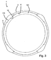
- Fig. 3 shows another cross section view of the clamp 1, however secured on the outside of an inner ring-shaped element 101.
- the ring-shaped element 101 exhibits recesses 113 for receiving and for engagement with the locking pads 13 of the locking arms 5.
- Fig. 4 is an enlarged cross section view of the engagement region of a locking pad 13 and the recess 113.
- Fig. 5 shows the inner ring shaped element 101 in a perspective view without the clamp 1 attached. In this figure, two of the recesses 113 can be seen.
- Fig. 6 shows the same inner ring shaped element 101 as Fig. 5 , with a clamp 1 connected to it.
- Fig. 7 shows a cut through a clamp 1 and the inner ring shaped element 101, illustrating how the pads 13 extend into the recess 113 in the inner element 101.
- Fig. 8 illustrates a practical use of the clamp 1 according to the invention.
- the inner ring shaped element 101 is a piece of pipe adapted to constitute a part of a string of production tubing (not shown).
- it can advantageously have threads in each end which mates with the threads of the elements of the production tubing.
- a pressure and temperature gauge 201 is arranged between two clamps 1 by welding to at least one of the clamps 1.
- a transformer coil is also welded to the same clamp.
- a third clamp is used to protect it and keep the transformer coil in position.
- Fig. 9 shows an alternative embodiment of a clamp 1 according to the present invention.
- This clamp 1 includes grooves 17 for passing electrical and hydraulic control lines (not shown) for various downhole equipment.
- the purpose of the clamp 1 is to guide and protect the cables during installation and operation.
- Fig. 10 illustrates yet an alternative embodiment, not forming part of the invention of the clamp 1.
- This clamp 1' is adapted to lock inside an outer circular element 101', such as a bore.
- the clamp 1' has a main body 3', a locking arm 5' with a locking pad 13' which is adapted to protrude into a recess 113' in the outer element 101'.
- a manipulation interface 15' is arranged in the locking arm 5'.
- the locking pads 13' protrudes radially beyond an outer diameter 4' of the main body 3, when in the non-bent or non-moved position.
- the groove 17 shown in Fig. 9 could also be provided for an embodiment as shown in Fig. 10 .
- the groove would then exist between two protrusions which would extend radially inwards.
Landscapes
- Engineering & Computer Science (AREA)
- Mining & Mineral Resources (AREA)
- Life Sciences & Earth Sciences (AREA)
- Geology (AREA)
- General Engineering & Computer Science (AREA)
- Mechanical Engineering (AREA)
- Physics & Mathematics (AREA)
- General Life Sciences & Earth Sciences (AREA)
- Fluid Mechanics (AREA)
- Geochemistry & Mineralogy (AREA)
- Environmental & Geological Engineering (AREA)
- Geophysics (AREA)
- Clamps And Clips (AREA)
- Supports For Pipes And Cables (AREA)
- Earth Drilling (AREA)
- Percussive Tools And Related Accessories (AREA)
- Pharmaceuticals Containing Other Organic And Inorganic Compounds (AREA)
Description
- The present invention relates to a clamp for securing various equipment to ring shaped structures or bores, especially to pipes used in the field of hydrocarbon wells, see for example
GB 763 694 - In the field of hydrocarbon wells, it is known to insert various types of measuring equipment into the well to measure downhole conditions. For instance pressure and temperature gauges are secured to the end of or a part of a production pipe string which is inserted into the well to bring the gauges to the point of measurement.
- One method of securing the equipment to the pipe is to fasten ring-shaped clamps to the external diameter of the pipe, and connect the equipment in question to the clamps, for instance by welding. Connecting the clamps should be fast and reliable. To avoid costly retrieving operations or loosing equipment, one should be certain that neither the clamps nor the secured equipment is lost in the well.
- In addition, an advantageous clamp exhibits small radial dimensions since it in a downhole application will be used in a limited space. Such a space is typically the annulus between the casing of a well and the production bore extending through it.
- The present invention provides a clamp that complies with these requirements.
- The present invention provides a clamp comprising a main body which is adapted to encircle an inner element, such as a pipe, to which the clamp can releasably connect. An axially extending opening extends through the main body. According to the present invention, the clamp comprises a locking arm which is connected to the main body at a base end, and which can bend elastically to move its oppositely positioned free end in a substantially radial direction. The locking arm comprises a locking pad at a distance from the base end, which in a locking position of the locking arm extends radially beyond an inner or outer diameter, respectively, of the main body. The locking pad is adapted to engage with a recess in said inner or outer element.
- The locking arm can extend substantially along the curvature of the main body, along a part of the circumference of the main body
- According to a preferred embodiment of the invention, the clamp has at least two locking arms, wherein at least one locking arm extends in a clockwise direction from its base end and at least one extends in an anti-clockwise direction. Such an embodiment of the clamp contributes in the ability to adsorb large torques in both directions.
- Preferably, the clamp comprises a plurality of locking pads which are distributed at substantially equal mutual distances along said inner or outer diameter.
- In yet another advantageous embodiment, the locking arm or arms comprise a manipulation interface, such as a threaded hole, for engagement when bending it in said substantially radial direction. Such a manipulation interface can for instance be adapted for engagement with a tool that can bend the locking arm between a locking position and an unlocked position. Particularly when the clamp comprises a plurality of locking arms, such as four or even more, such a tool can make a connection and disconnection process more feasible than performing the operations manually.
- The clamp, with its main body, locking arm(s), and the locking pad(s) is preferably in one piece. That is, the components are for instance manufactured from the same piece or joined together to be non-detachable, such as by welding. The advantage is that no loose parts that can fall off from the clamp into a down hole completion. Thus, such a clamp is without bolts or other detachable components.
- Yet another preferred technical feature of the clamp according to the invention is that the locking arm is arranged between two slits, one arranged on each longitudinal side of the locking arm. The slits are advantageously arranged between the locking arm and the main body.
- The clamp can comprise an axially extending guiding groove arranged on the opposite radial side of the main body with respect to the locking pad
- With a clamp according to the present invention, one obtains a clamp with a small radial extension. This is particularly advantageous when used in the restricted spaces in hydrocarbon wells. Also, as mentioned above, without any loose or detachable parts, one does not risk that a part of the clamp is lost into the well. In addition one obtains a clamp which is easily attachable and detachable.
- When used in a hydrocarbon well, as is regarded as the main purpose of the clamp according to the invention, the clamp shall both fix various equipment in correct position and protect the equipment from impact and applied loads during the whole lifetime.
- Having described the clamp according to the invention in general terms, a more specific example of preferred embodiment will now be presented with reference to the drawings, in which
- Fig. 1
- is a perspective view of a clamp according to the present invention;
- Fig. 2
- is a cross section view of the clamp in
Fig. 1 ; - Fig. 3
- is a cross section view of the clamp and an inner ring-shaped element;
- Fig. 4
- is an enlarged cross section view of an engagement region;
- Fig. 5
- is a perspective part view of an inner element to which the clamp secures;
- Fig. 6
- is the perspective view of
Fig. 5 , with the clamp attached; - Fig. 7
- is a perspective view of an axial cut through the clamp and a pipe to which it is connected;
- Fig. 8
- is a view of an advantageous application of the clamp;
- Fig. 9
- is a perspective view of another embodiment of a clamp according to the invention; and
- Fig. 10
- is an enlarged cross section view of yet an alternative embodiment not forming part of the invention of the clamp.
-
Fig. 1 shows aclamp 1 according to the invention. The shownclamp 1 has a ring-shapedmain body 3, to which four lockingarms 5 are connected. The lockingarms 5 substantially follow the same curvature as the ring shape of themain body 3. Furthermore, the lockingarms 5 are fastened to the main body at theirbase end 7. Their oppositefree end 9 can be moved in a radial direction by bending of thelocking arm 5. Thus, the lockingarms 5 exhibit some flexibility along the radial plane. Advantageously, the lockingarms 5 have such an extension in the axial direction A that they exhibit stiffness in the axial direction. In addition, due to the narrowness ofslits 11 on each axially facing side of the lockingarms 5, between the lockingarms 5 and themain body 3, any movement of the lockingarms 5 in the axial direction A would be halted by abutment of the lockingarms 5 against themain body 3. - On the radially inwardly facing side of the
locking arm 5, in the region of thefree end 9, the lockingarms 5 exhibit alocking pad 13. Thelocking pad 13 extends further radially inward than aninner diameter 4 of themain body 3. It is adapted to engage with a facing recess 113 (seeFig. 3 ) arranged in the outer face of a ring-shaped member 101 (Fig. 3 ) to which theclamp 1 connects. This will be described further below. - On the radially outwardly facing side of the
locking arm 5, in the region of thefree end 9, the lockingarm 5 has amanipulation interface 15 in the form of a threaded hole. In order to move thelocking pad 13 out of engagement with therecess 113, an operator can advantageously connect to the threaded hole with a simple screw or with a suitable tool (not shown). - Instead of having the locking
arms 5 arranged within themain body 3, one could also imagine them to be arranged on an axial end of themain body 3. In such an embodiment, however, only oneslit 11 would contribute to maintaining the axial position. One could also imagine having lockingarms 5 on both axial sides of themain body 3. - One could even imagine that instead of the
slits 11, there could be voids (not shown). In such an embodiment, the locking arm(s) 5 would not abut against themain body 3 if an axially directed force was exerted onto theclamp 1. A torque force would then arise at thebase end 7 of thelocking arm 5. - In addition, one could also imagine having only one
locking arm 3. However, a plurality of lockingarms 5, as shown inFig. 1 , contributes to advantageous distribution of both axial forces and torques. - Furthermore, in stead of having the locking
arms 5 extending in the tangential direction, substantially along the curvature of the main body 3 (as shown inFig. 1 ), one could imagine an embodiment where the locking arms would extend in the axial direction. The locking arms could then be arranged between slits between the locking arms and the main body, or they could extend in an axial direction beyond the structure of the main body. -
Fig. 2 shows a cross section view of theclamp 1 inFig. 1 . As shown inFig. 2 , thelocking pads 13 are preferably symmetrically distributed along the inner diameter of themain body 3, in order to obtain an even distribution of forces between theclamp 1 and the inner ring shaped element 101 (Fig. 3 ). Also, of the four lockingarms 5 shown inFig. 1 andFig. 2 , two extend clockwise from their base ends 7, whereas the other two extend anti-clockwise. This feature contributes in withstanding torques in both directions. - An additional advantageous feature is to design the locking
arms 5 with different resonance frequencies in order to overcome resonance problems due to vibration. -
Fig. 3 shows another cross section view of theclamp 1, however secured on the outside of an inner ring-shapedelement 101. As mentioned above, the ring-shapedelement 101exhibits recesses 113 for receiving and for engagement with thelocking pads 13 of the lockingarms 5.Fig. 4 is an enlarged cross section view of the engagement region of alocking pad 13 and therecess 113. -
Fig. 5 shows the inner ring shapedelement 101 in a perspective view without theclamp 1 attached. In this figure, two of therecesses 113 can be seen.Fig. 6 shows the same inner ring shapedelement 101 asFig. 5 , with aclamp 1 connected to it. -
Fig. 7 shows a cut through aclamp 1 and the inner ring shapedelement 101, illustrating how thepads 13 extend into therecess 113 in theinner element 101. -
Fig. 8 illustrates a practical use of theclamp 1 according to the invention. In this embodiment, the inner ring shapedelement 101 is a piece of pipe adapted to constitute a part of a string of production tubing (not shown). Thus it can advantageously have threads in each end which mates with the threads of the elements of the production tubing. - In this example, a pressure and
temperature gauge 201 is arranged between twoclamps 1 by welding to at least one of theclamps 1. A transformer coil is also welded to the same clamp. A third clamp is used to protect it and keep the transformer coil in position. -
Fig. 9 shows an alternative embodiment of aclamp 1 according to the present invention. Thisclamp 1 includesgrooves 17 for passing electrical and hydraulic control lines (not shown) for various downhole equipment. The purpose of theclamp 1 is to guide and protect the cables during installation and operation. -
Fig. 10 illustrates yet an alternative embodiment, not forming part of the invention of theclamp 1. This clamp 1' is adapted to lock inside an outer circular element 101', such as a bore. As the embodiments described above, the clamp 1' has a main body 3', a locking arm 5' with a locking pad 13' which is adapted to protrude into a recess 113' in the outer element 101'. In order to bend the locking arm 5' radially inwards to release the locking pad 13' from engagement with the recess 113', a manipulation interface 15' is arranged in the locking arm 5'. In this embodiment of the clamp 1' according to the invention, the locking pads 13' protrudes radially beyond an outer diameter 4' of themain body 3, when in the non-bent or non-moved position. - The
groove 17 shown inFig. 9 could also be provided for an embodiment as shown inFig. 10 . The groove would then exist between two protrusions which would extend radially inwards.
Claims (9)
- Clamp (1) comprising a main body (3) which is adapted to encircle an inner element (101), such as a pipe, to which the clamp (1) can releasably connect, and wherein an axially extending opening extends through the main body (3) wherein the clamp- comprises a locking arm (5) which is connected to said main body (3) at a base end (7), and which can bend elastically to move its oppositely positioned free end (9) in a substantially radial direction; and- the locking arm (5) comprises a locking pad (13) at a distance from the base end (7), which in a locking position of the locking arm (5) extends radially beyond an inner (4) diameter of the main body (3);
characterized in that said locking pad (13) is adapted to engage with a recess (113) in said inner (101) element. - Clamp (1) according to claim 1, characterized in that the locking arm (5) substantially extends along the curvature of the main body (3), along a part of the circumference of the main body (3).
- Clamp (1) according to claim 2, characterized in that it comprises at least two locking arms (5), wherein at least one locking arm (5) extends in a clockwise direction from its base end (7) and at least one extends in an anti-clockwise direction.
- Clamp (1) according to claim 1, 2 or 3, characterized in that it comprises a plurality of locking pads (13) which are distributed at substantially equal mutual distances along said inner or outer diameter.
- Clamp (1) according to one of the preceding claims, characterized in that the locking arm(s) (5) comprise a manipulation interface (15), such as a threaded hole, for engagement when bending it in said substantially radial direction.
- Clamp (1) according to one of the preceding claims, characterized in that the main body (3), locking arm(s) (5) and the locking pad(s) (13) are in one piece.
- Clamp (1) according to any one of the preceding claims, characterized in that the locking arm(s) (5) is arranged between two slits (11), one arranged on each longitudinal side of the locking arm (5), which slits (11) are arranged between the locking arm (5) and the main body (3).
- Clamp (1) according to any one of the preceding claims, characterized in that it comprises an axially extending guiding groove (17) arranged on the opposite radial side of the main body (3) with respect to the locking pad (13).
- Clamp (1) according to any one of the preceding claims, characterized in that it is attached to a production tubing extending into a hydrocarbon well.
Applications Claiming Priority (2)
| Application Number | Priority Date | Filing Date | Title |
|---|---|---|---|
| NO20101117A NO334036B1 (en) | 2010-08-06 | 2010-08-06 | Clamp |
| PCT/EP2011/063506 WO2012017065A2 (en) | 2010-08-06 | 2011-08-05 | Clamp |
Publications (2)
| Publication Number | Publication Date |
|---|---|
| EP2601374A2 EP2601374A2 (en) | 2013-06-12 |
| EP2601374B1 true EP2601374B1 (en) | 2014-07-09 |
Family
ID=44629597
Family Applications (1)
| Application Number | Title | Priority Date | Filing Date |
|---|---|---|---|
| EP11739094.8A Not-in-force EP2601374B1 (en) | 2010-08-06 | 2011-08-05 | Clamp |
Country Status (6)
| Country | Link |
|---|---|
| US (1) | US9404617B2 (en) |
| EP (1) | EP2601374B1 (en) |
| CN (1) | CN103097643B (en) |
| DK (1) | DK2601374T3 (en) |
| NO (1) | NO334036B1 (en) |
| WO (1) | WO2012017065A2 (en) |
Families Citing this family (4)
| Publication number | Priority date | Publication date | Assignee | Title |
|---|---|---|---|---|
| EP3550291A1 (en) * | 2018-04-05 | 2019-10-09 | Georg Fischer Rohrleitungssysteme AG | Fastening device for measuring devices on pipes |
| CN111824388A (en) * | 2019-04-18 | 2020-10-27 | 成都飞机工业(集团)有限责任公司 | Fixed wing unmanned aerial vehicle tail boom hangs |
| US11649692B2 (en) | 2020-07-14 | 2023-05-16 | Saudi Arabian Oil Company | System and method for cementing a wellbore |
| CA3130321A1 (en) * | 2020-09-10 | 2022-03-10 | Harrison Jet Guns II, L.P. | Oilfield perforating self-positioning systems and methods |
Family Cites Families (33)
| Publication number | Priority date | Publication date | Assignee | Title |
|---|---|---|---|---|
| US2628134A (en) | 1948-07-17 | 1953-02-10 | Ventura Tool Company | Protective collar for drill pipes |
| US2846016A (en) * | 1954-03-19 | 1958-08-05 | Huntsinger Associates | Stop collar for well casing |
| US3652138A (en) * | 1970-04-23 | 1972-03-28 | Charles H Collett | Self-locking snap-on collar for oil well operations |
| US3999811A (en) | 1975-08-25 | 1976-12-28 | Bryon Jackson, Inc. | Drill pipe protector |
| US4349048A (en) * | 1980-12-17 | 1982-09-14 | Superior Casing Crews, Inc. | Pipe thread protector |
| US4600063A (en) * | 1984-05-29 | 1986-07-15 | Dailey Petroleum Services Corp. | Double-taper slip-on drill string stabilizer |
| US5095981A (en) * | 1986-10-30 | 1992-03-17 | Mikolajczyk Raymond F | Casing centralizer |
| CN2182259Y (en) * | 1993-03-01 | 1994-11-09 | 张洪昌 | Hook wedging type pipe cable clamp holder |
| US5833019A (en) * | 1996-11-27 | 1998-11-10 | Pegasus International Inc. | Pipe protector |
| GB0001435D0 (en) * | 2000-01-22 | 2000-03-08 | Downhole Products Plc | Centraliser |
| CA2350002C (en) | 2000-06-08 | 2007-10-09 | Emery W. Davis | Wire guard device for wells |
| WO2001098621A2 (en) * | 2000-06-21 | 2001-12-27 | Derek Frederick Herrera | Centraliser |
| IT1319550B1 (en) * | 2000-12-15 | 2003-10-20 | Eni Spa | METHOD FOR CENTRALIZATION OF COLUMNS FOR LEANPROFILE APPLICATIONS |
| GB0115704D0 (en) * | 2001-06-27 | 2001-08-22 | Winapex Ltd | Centering device |
| US7140431B2 (en) * | 2001-07-06 | 2006-11-28 | Shell Oil Company | Centraliser for an expandable tubular element in a wellbore |
| BR0210969A (en) * | 2001-07-10 | 2004-06-08 | Shell Int Research | Stabilizer for a radially expandable tubular element |
| US6679325B2 (en) * | 2002-02-08 | 2004-01-20 | Frank's International, Inc. | Minimum clearance bow-spring centralizer |
| CA2378134A1 (en) * | 2002-03-11 | 2003-09-11 | Top-Co Industries Ltd. | Casing centralizer |
| US6880789B2 (en) * | 2003-09-04 | 2005-04-19 | Illinois Tool Works Inc. | Clip device |
| US7357434B2 (en) * | 2003-10-21 | 2008-04-15 | Frank's International, Inc. | Load ring for lifting by elevator, of casing having no upset |
| US7159619B2 (en) * | 2003-10-21 | 2007-01-09 | Frank's International, Inc. | Thread protector for use on pin end of oilfield tubulars |
| US7237607B2 (en) * | 2003-12-08 | 2007-07-03 | Tesco Corporation | Tubular stabbing protector and method |
| FR2878930B1 (en) * | 2004-12-07 | 2008-06-27 | Leroux & Lotz Technologies Sa | DEVICE, IN PARTICULAR FOR FIXING A FLOATING ELEMENT TO A CONDUIT |
| GB0513734D0 (en) * | 2005-07-05 | 2005-08-10 | Thornton Thomas J O | Improved centraliser |
| GB2444060B (en) * | 2006-11-21 | 2008-12-17 | Swelltec Ltd | Downhole apparatus and method |
| US7878241B2 (en) * | 2007-05-16 | 2011-02-01 | Frank's International, Inc. | Expandable centralizer for expandable pipe string |
| GB0723607D0 (en) * | 2007-12-03 | 2008-01-09 | Petrowell Ltd | Improved centraliser |
| WO2010006357A1 (en) * | 2008-07-15 | 2010-01-21 | Kwik-Zip Pty Ltd | Borehole casing centraliser |
| US8863834B2 (en) * | 2009-04-07 | 2014-10-21 | Antelope Oil Tool & Mfg. Co., Llc | Friction reducing wear band and method of coupling a wear band to a tubular |
| US8245779B2 (en) * | 2009-08-07 | 2012-08-21 | Geodaq, Inc. | Centralizer apparatus |
| US20120061076A1 (en) * | 2010-09-10 | 2012-03-15 | Frank's International, Inc. | Stop Collar for Tubulars |
| US8646519B2 (en) * | 2010-12-17 | 2014-02-11 | Sondex Wireline Limited | Low-profile suspension of logging sensor and method |
| US9234418B2 (en) * | 2011-05-31 | 2016-01-12 | Schlumberger Technology Corporation | Self-tightening clamps to secure tools along the exterior diameter of a tubing |
-
2010
- 2010-08-06 NO NO20101117A patent/NO334036B1/en not_active IP Right Cessation
-
2011
- 2011-08-05 WO PCT/EP2011/063506 patent/WO2012017065A2/en not_active Ceased
- 2011-08-05 US US13/813,283 patent/US9404617B2/en not_active Expired - Fee Related
- 2011-08-05 CN CN201180033903.4A patent/CN103097643B/en not_active Expired - Fee Related
- 2011-08-05 EP EP11739094.8A patent/EP2601374B1/en not_active Not-in-force
- 2011-08-05 DK DK11739094.8T patent/DK2601374T3/en active
Also Published As
| Publication number | Publication date |
|---|---|
| WO2012017065A2 (en) | 2012-02-09 |
| DK2601374T3 (en) | 2014-09-15 |
| NO334036B1 (en) | 2013-11-25 |
| EP2601374A2 (en) | 2013-06-12 |
| CN103097643A (en) | 2013-05-08 |
| US20130175417A1 (en) | 2013-07-11 |
| WO2012017065A3 (en) | 2012-08-16 |
| NO20101117A1 (en) | 2012-02-07 |
| CN103097643B (en) | 2015-08-26 |
| US9404617B2 (en) | 2016-08-02 |
Similar Documents
| Publication | Publication Date | Title |
|---|---|---|
| US9404617B2 (en) | Clamp | |
| EP2872725B1 (en) | Device arranged for attaching a mandrel on a tubular body | |
| NO346314B1 (en) | Alignment sub With deformable sleeve | |
| US10337260B2 (en) | Cable protecting device | |
| US11448343B2 (en) | Fastening means for fastening of a cable to a tubular body | |
| JP7375190B2 (en) | Equipment for steel pipes and steel pipes used in hydrocarbon well tubular columns and hydrocarbon well tubular columns | |
| KR20170042788A (en) | High torque polymer fittings | |
| US12129716B2 (en) | Securing system intended to secure a cable to a tube | |
| EP1412608A1 (en) | Downhole release joint | |
| US11939822B2 (en) | Control line protector assembly | |
| GB2591027A (en) | Control line clamp system | |
| US11761272B2 (en) | Method for attaching a control line clamp | |
| JP5645964B2 (en) | A set for achieving a threaded connection structure, a method for achieving a threaded connection structure, a connection structure achieved using the method, a double connection structure constituted by the connection structure, a method for disassembling the threaded connection structure, And use of the connection structure | |
| US10337259B2 (en) | Maintaining tension of a transmission line in a tubular | |
| US12560080B2 (en) | Umbilical protection and structural reinforcement joint for completion and workover riser | |
| CN111005911B (en) | A embracing ring quick detach structure for hydro-cylinder connector | |
| US20210231256A1 (en) | Slip-On Splice-Filter Cage | |
| WO2019234126A1 (en) | Attachment device | |
| CN116398058B (en) | Sucker rod connection structure and sucker rod string | |
| CN114658169A (en) | Steel bar connecting structure | |
| WO2017148497A1 (en) | Well tool device |
Legal Events
| Date | Code | Title | Description |
|---|---|---|---|
| PUAI | Public reference made under article 153(3) epc to a published international application that has entered the european phase |
Free format text: ORIGINAL CODE: 0009012 |
|
| 17P | Request for examination filed |
Effective date: 20130123 |
|
| AK | Designated contracting states |
Kind code of ref document: A2 Designated state(s): AL AT BE BG CH CY CZ DE DK EE ES FI FR GB GR HR HU IE IS IT LI LT LU LV MC MK MT NL NO PL PT RO RS SE SI SK SM TR |
|
| DAX | Request for extension of the european patent (deleted) | ||
| GRAP | Despatch of communication of intention to grant a patent |
Free format text: ORIGINAL CODE: EPIDOSNIGR1 |
|
| INTG | Intention to grant announced |
Effective date: 20140114 |
|
| GRAP | Despatch of communication of intention to grant a patent |
Free format text: ORIGINAL CODE: EPIDOSNIGR1 |
|
| INTG | Intention to grant announced |
Effective date: 20140311 |
|
| GRAS | Grant fee paid |
Free format text: ORIGINAL CODE: EPIDOSNIGR3 |
|
| GRAA | (expected) grant |
Free format text: ORIGINAL CODE: 0009210 |
|
| AK | Designated contracting states |
Kind code of ref document: B1 Designated state(s): AL AT BE BG CH CY CZ DE DK EE ES FI FR GB GR HR HU IE IS IT LI LT LU LV MC MK MT NL NO PL PT RO RS SE SI SK SM TR |
|
| REG | Reference to a national code |
Ref country code: GB Ref legal event code: FG4D |
|
| REG | Reference to a national code |
Ref country code: CH Ref legal event code: EP Ref country code: AT Ref legal event code: REF Ref document number: 676662 Country of ref document: AT Kind code of ref document: T Effective date: 20140715 |
|
| REG | Reference to a national code |
Ref country code: IE Ref legal event code: FG4D |
|
| REG | Reference to a national code |
Ref country code: DE Ref legal event code: R096 Ref document number: 602011008283 Country of ref document: DE Effective date: 20140821 |
|
| REG | Reference to a national code |
Ref country code: DK Ref legal event code: T3 Effective date: 20140908 |
|
| REG | Reference to a national code |
Ref country code: NL Ref legal event code: T3 |
|
| REG | Reference to a national code |
Ref country code: AT Ref legal event code: MK05 Ref document number: 676662 Country of ref document: AT Kind code of ref document: T Effective date: 20140709 |
|
| REG | Reference to a national code |
Ref country code: LT Ref legal event code: MG4D |
|
| PG25 | Lapsed in a contracting state [announced via postgrant information from national office to epo] |
Ref country code: GR Free format text: LAPSE BECAUSE OF FAILURE TO SUBMIT A TRANSLATION OF THE DESCRIPTION OR TO PAY THE FEE WITHIN THE PRESCRIBED TIME-LIMIT Effective date: 20141010 Ref country code: NO Free format text: LAPSE BECAUSE OF FAILURE TO SUBMIT A TRANSLATION OF THE DESCRIPTION OR TO PAY THE FEE WITHIN THE PRESCRIBED TIME-LIMIT Effective date: 20141009 Ref country code: BG Free format text: LAPSE BECAUSE OF FAILURE TO SUBMIT A TRANSLATION OF THE DESCRIPTION OR TO PAY THE FEE WITHIN THE PRESCRIBED TIME-LIMIT Effective date: 20141009 Ref country code: FI Free format text: LAPSE BECAUSE OF FAILURE TO SUBMIT A TRANSLATION OF THE DESCRIPTION OR TO PAY THE FEE WITHIN THE PRESCRIBED TIME-LIMIT Effective date: 20140709 Ref country code: SE Free format text: LAPSE BECAUSE OF FAILURE TO SUBMIT A TRANSLATION OF THE DESCRIPTION OR TO PAY THE FEE WITHIN THE PRESCRIBED TIME-LIMIT Effective date: 20140709 Ref country code: ES Free format text: LAPSE BECAUSE OF FAILURE TO SUBMIT A TRANSLATION OF THE DESCRIPTION OR TO PAY THE FEE WITHIN THE PRESCRIBED TIME-LIMIT Effective date: 20140709 Ref country code: LT Free format text: LAPSE BECAUSE OF FAILURE TO SUBMIT A TRANSLATION OF THE DESCRIPTION OR TO PAY THE FEE WITHIN THE PRESCRIBED TIME-LIMIT Effective date: 20140709 Ref country code: PT Free format text: LAPSE BECAUSE OF FAILURE TO SUBMIT A TRANSLATION OF THE DESCRIPTION OR TO PAY THE FEE WITHIN THE PRESCRIBED TIME-LIMIT Effective date: 20141110 |
|
| PG25 | Lapsed in a contracting state [announced via postgrant information from national office to epo] |
Ref country code: HR Free format text: LAPSE BECAUSE OF FAILURE TO SUBMIT A TRANSLATION OF THE DESCRIPTION OR TO PAY THE FEE WITHIN THE PRESCRIBED TIME-LIMIT Effective date: 20140709 Ref country code: PL Free format text: LAPSE BECAUSE OF FAILURE TO SUBMIT A TRANSLATION OF THE DESCRIPTION OR TO PAY THE FEE WITHIN THE PRESCRIBED TIME-LIMIT Effective date: 20140709 Ref country code: CY Free format text: LAPSE BECAUSE OF FAILURE TO SUBMIT A TRANSLATION OF THE DESCRIPTION OR TO PAY THE FEE WITHIN THE PRESCRIBED TIME-LIMIT Effective date: 20140709 Ref country code: AT Free format text: LAPSE BECAUSE OF FAILURE TO SUBMIT A TRANSLATION OF THE DESCRIPTION OR TO PAY THE FEE WITHIN THE PRESCRIBED TIME-LIMIT Effective date: 20140709 Ref country code: IS Free format text: LAPSE BECAUSE OF FAILURE TO SUBMIT A TRANSLATION OF THE DESCRIPTION OR TO PAY THE FEE WITHIN THE PRESCRIBED TIME-LIMIT Effective date: 20141109 Ref country code: LV Free format text: LAPSE BECAUSE OF FAILURE TO SUBMIT A TRANSLATION OF THE DESCRIPTION OR TO PAY THE FEE WITHIN THE PRESCRIBED TIME-LIMIT Effective date: 20140709 Ref country code: RS Free format text: LAPSE BECAUSE OF FAILURE TO SUBMIT A TRANSLATION OF THE DESCRIPTION OR TO PAY THE FEE WITHIN THE PRESCRIBED TIME-LIMIT Effective date: 20140709 |
|
| REG | Reference to a national code |
Ref country code: CH Ref legal event code: PL |
|
| REG | Reference to a national code |
Ref country code: DE Ref legal event code: R097 Ref document number: 602011008283 Country of ref document: DE |
|
| PG25 | Lapsed in a contracting state [announced via postgrant information from national office to epo] |
Ref country code: LI Free format text: LAPSE BECAUSE OF NON-PAYMENT OF DUE FEES Effective date: 20140831 Ref country code: SK Free format text: LAPSE BECAUSE OF FAILURE TO SUBMIT A TRANSLATION OF THE DESCRIPTION OR TO PAY THE FEE WITHIN THE PRESCRIBED TIME-LIMIT Effective date: 20140709 Ref country code: BE Free format text: LAPSE BECAUSE OF NON-PAYMENT OF DUE FEES Effective date: 20140831 Ref country code: CH Free format text: LAPSE BECAUSE OF NON-PAYMENT OF DUE FEES Effective date: 20140831 Ref country code: IT Free format text: LAPSE BECAUSE OF FAILURE TO SUBMIT A TRANSLATION OF THE DESCRIPTION OR TO PAY THE FEE WITHIN THE PRESCRIBED TIME-LIMIT Effective date: 20140709 Ref country code: MC Free format text: LAPSE BECAUSE OF FAILURE TO SUBMIT A TRANSLATION OF THE DESCRIPTION OR TO PAY THE FEE WITHIN THE PRESCRIBED TIME-LIMIT Effective date: 20140709 Ref country code: EE Free format text: LAPSE BECAUSE OF FAILURE TO SUBMIT A TRANSLATION OF THE DESCRIPTION OR TO PAY THE FEE WITHIN THE PRESCRIBED TIME-LIMIT Effective date: 20140709 Ref country code: CZ Free format text: LAPSE BECAUSE OF FAILURE TO SUBMIT A TRANSLATION OF THE DESCRIPTION OR TO PAY THE FEE WITHIN THE PRESCRIBED TIME-LIMIT Effective date: 20140709 |
|
| PLBE | No opposition filed within time limit |
Free format text: ORIGINAL CODE: 0009261 |
|
| STAA | Information on the status of an ep patent application or granted ep patent |
Free format text: STATUS: NO OPPOSITION FILED WITHIN TIME LIMIT |
|
| REG | Reference to a national code |
Ref country code: IE Ref legal event code: MM4A |
|
| 26N | No opposition filed |
Effective date: 20150410 |
|
| REG | Reference to a national code |
Ref country code: FR Ref legal event code: PLFP Year of fee payment: 5 |
|
| PG25 | Lapsed in a contracting state [announced via postgrant information from national office to epo] |
Ref country code: IE Free format text: LAPSE BECAUSE OF NON-PAYMENT OF DUE FEES Effective date: 20140805 |
|
| PG25 | Lapsed in a contracting state [announced via postgrant information from national office to epo] |
Ref country code: SI Free format text: LAPSE BECAUSE OF FAILURE TO SUBMIT A TRANSLATION OF THE DESCRIPTION OR TO PAY THE FEE WITHIN THE PRESCRIBED TIME-LIMIT Effective date: 20140709 |
|
| PG25 | Lapsed in a contracting state [announced via postgrant information from national office to epo] |
Ref country code: SM Free format text: LAPSE BECAUSE OF FAILURE TO SUBMIT A TRANSLATION OF THE DESCRIPTION OR TO PAY THE FEE WITHIN THE PRESCRIBED TIME-LIMIT Effective date: 20140709 |
|
| PG25 | Lapsed in a contracting state [announced via postgrant information from national office to epo] |
Ref country code: RO Free format text: LAPSE BECAUSE OF FAILURE TO SUBMIT A TRANSLATION OF THE DESCRIPTION OR TO PAY THE FEE WITHIN THE PRESCRIBED TIME-LIMIT Effective date: 20140709 |
|
| PG25 | Lapsed in a contracting state [announced via postgrant information from national office to epo] |
Ref country code: MT Free format text: LAPSE BECAUSE OF FAILURE TO SUBMIT A TRANSLATION OF THE DESCRIPTION OR TO PAY THE FEE WITHIN THE PRESCRIBED TIME-LIMIT Effective date: 20140709 |
|
| PG25 | Lapsed in a contracting state [announced via postgrant information from national office to epo] |
Ref country code: LU Free format text: LAPSE BECAUSE OF NON-PAYMENT OF DUE FEES Effective date: 20140805 Ref country code: TR Free format text: LAPSE BECAUSE OF FAILURE TO SUBMIT A TRANSLATION OF THE DESCRIPTION OR TO PAY THE FEE WITHIN THE PRESCRIBED TIME-LIMIT Effective date: 20140709 Ref country code: HU Free format text: LAPSE BECAUSE OF FAILURE TO SUBMIT A TRANSLATION OF THE DESCRIPTION OR TO PAY THE FEE WITHIN THE PRESCRIBED TIME-LIMIT; INVALID AB INITIO Effective date: 20110805 Ref country code: BE Free format text: LAPSE BECAUSE OF FAILURE TO SUBMIT A TRANSLATION OF THE DESCRIPTION OR TO PAY THE FEE WITHIN THE PRESCRIBED TIME-LIMIT Effective date: 20140709 |
|
| REG | Reference to a national code |
Ref country code: FR Ref legal event code: PLFP Year of fee payment: 6 |
|
| REG | Reference to a national code |
Ref country code: FR Ref legal event code: PLFP Year of fee payment: 7 |
|
| PG25 | Lapsed in a contracting state [announced via postgrant information from national office to epo] |
Ref country code: MK Free format text: LAPSE BECAUSE OF FAILURE TO SUBMIT A TRANSLATION OF THE DESCRIPTION OR TO PAY THE FEE WITHIN THE PRESCRIBED TIME-LIMIT Effective date: 20140709 |
|
| REG | Reference to a national code |
Ref country code: FR Ref legal event code: PLFP Year of fee payment: 8 |
|
| PG25 | Lapsed in a contracting state [announced via postgrant information from national office to epo] |
Ref country code: AL Free format text: LAPSE BECAUSE OF FAILURE TO SUBMIT A TRANSLATION OF THE DESCRIPTION OR TO PAY THE FEE WITHIN THE PRESCRIBED TIME-LIMIT Effective date: 20140709 |
|
| PGFP | Annual fee paid to national office [announced via postgrant information from national office to epo] |
Ref country code: FR Payment date: 20180827 Year of fee payment: 8 Ref country code: DE Payment date: 20180829 Year of fee payment: 8 Ref country code: NL Payment date: 20180826 Year of fee payment: 8 |
|
| PGFP | Annual fee paid to national office [announced via postgrant information from national office to epo] |
Ref country code: DK Payment date: 20180829 Year of fee payment: 8 Ref country code: GB Payment date: 20180828 Year of fee payment: 8 |
|
| REG | Reference to a national code |
Ref country code: DE Ref legal event code: R119 Ref document number: 602011008283 Country of ref document: DE |
|
| REG | Reference to a national code |
Ref country code: DK Ref legal event code: EBP Effective date: 20190831 |
|
| REG | Reference to a national code |
Ref country code: NL Ref legal event code: MM Effective date: 20190901 |
|
| GBPC | Gb: european patent ceased through non-payment of renewal fee |
Effective date: 20190805 |
|
| PG25 | Lapsed in a contracting state [announced via postgrant information from national office to epo] |
Ref country code: DK Free format text: LAPSE BECAUSE OF NON-PAYMENT OF DUE FEES Effective date: 20190831 Ref country code: NL Free format text: LAPSE BECAUSE OF NON-PAYMENT OF DUE FEES Effective date: 20190901 Ref country code: FR Free format text: LAPSE BECAUSE OF NON-PAYMENT OF DUE FEES Effective date: 20190831 Ref country code: DE Free format text: LAPSE BECAUSE OF NON-PAYMENT OF DUE FEES Effective date: 20200303 |
|
| PG25 | Lapsed in a contracting state [announced via postgrant information from national office to epo] |
Ref country code: GB Free format text: LAPSE BECAUSE OF NON-PAYMENT OF DUE FEES Effective date: 20190805 |