EP2601115B1 - Refrigeration transport container - Google Patents
Refrigeration transport container Download PDFInfo
- Publication number
- EP2601115B1 EP2601115B1 EP11814168.8A EP11814168A EP2601115B1 EP 2601115 B1 EP2601115 B1 EP 2601115B1 EP 11814168 A EP11814168 A EP 11814168A EP 2601115 B1 EP2601115 B1 EP 2601115B1
- Authority
- EP
- European Patent Office
- Prior art keywords
- container
- refrigeration
- air
- transport container
- floor
- Prior art date
- Legal status (The legal status is an assumption and is not a legal conclusion. Google has not performed a legal analysis and makes no representation as to the accuracy of the status listed.)
- Not-in-force
Links
Images

Classifications
-
- B—PERFORMING OPERATIONS; TRANSPORTING
- B65—CONVEYING; PACKING; STORING; HANDLING THIN OR FILAMENTARY MATERIAL
- B65D—CONTAINERS FOR STORAGE OR TRANSPORT OF ARTICLES OR MATERIALS, e.g. BAGS, BARRELS, BOTTLES, BOXES, CANS, CARTONS, CRATES, DRUMS, JARS, TANKS, HOPPERS, FORWARDING CONTAINERS; ACCESSORIES, CLOSURES, OR FITTINGS THEREFOR; PACKAGING ELEMENTS; PACKAGES
- B65D88/00—Large containers
- B65D88/74—Large containers having means for heating, cooling, aerating or other conditioning of contents
- B65D88/745—Large containers having means for heating, cooling, aerating or other conditioning of contents blowing or injecting heating, cooling or other conditioning fluid inside the container
-
- F—MECHANICAL ENGINEERING; LIGHTING; HEATING; WEAPONS; BLASTING
- F25—REFRIGERATION OR COOLING; COMBINED HEATING AND REFRIGERATION SYSTEMS; HEAT PUMP SYSTEMS; MANUFACTURE OR STORAGE OF ICE; LIQUEFACTION SOLIDIFICATION OF GASES
- F25D—REFRIGERATORS; COLD ROOMS; ICE-BOXES; COOLING OR FREEZING APPARATUS NOT OTHERWISE PROVIDED FOR
- F25D17/00—Arrangements for circulating cooling fluids; Arrangements for circulating gas, e.g. air, within refrigerated spaces
- F25D17/04—Arrangements for circulating cooling fluids; Arrangements for circulating gas, e.g. air, within refrigerated spaces for circulating air, e.g. by convection
- F25D17/06—Arrangements for circulating cooling fluids; Arrangements for circulating gas, e.g. air, within refrigerated spaces for circulating air, e.g. by convection by forced circulation
-
- F—MECHANICAL ENGINEERING; LIGHTING; HEATING; WEAPONS; BLASTING
- F25—REFRIGERATION OR COOLING; COMBINED HEATING AND REFRIGERATION SYSTEMS; HEAT PUMP SYSTEMS; MANUFACTURE OR STORAGE OF ICE; LIQUEFACTION SOLIDIFICATION OF GASES
- F25D—REFRIGERATORS; COLD ROOMS; ICE-BOXES; COOLING OR FREEZING APPARATUS NOT OTHERWISE PROVIDED FOR
- F25D2317/00—Details or arrangements for circulating cooling fluids; Details or arrangements for circulating gas, e.g. air, within refrigerated spaces, not provided for in other groups of this subclass
- F25D2317/06—Details or arrangements for circulating cooling fluids; Details or arrangements for circulating gas, e.g. air, within refrigerated spaces, not provided for in other groups of this subclass with forced air circulation
- F25D2317/065—Details or arrangements for circulating cooling fluids; Details or arrangements for circulating gas, e.g. air, within refrigerated spaces, not provided for in other groups of this subclass with forced air circulation characterised by the air return
- F25D2317/0655—Details or arrangements for circulating cooling fluids; Details or arrangements for circulating gas, e.g. air, within refrigerated spaces, not provided for in other groups of this subclass with forced air circulation characterised by the air return through the top
-
- F—MECHANICAL ENGINEERING; LIGHTING; HEATING; WEAPONS; BLASTING
- F25—REFRIGERATION OR COOLING; COMBINED HEATING AND REFRIGERATION SYSTEMS; HEAT PUMP SYSTEMS; MANUFACTURE OR STORAGE OF ICE; LIQUEFACTION SOLIDIFICATION OF GASES
- F25D—REFRIGERATORS; COLD ROOMS; ICE-BOXES; COOLING OR FREEZING APPARATUS NOT OTHERWISE PROVIDED FOR
- F25D2317/00—Details or arrangements for circulating cooling fluids; Details or arrangements for circulating gas, e.g. air, within refrigerated spaces, not provided for in other groups of this subclass
- F25D2317/06—Details or arrangements for circulating cooling fluids; Details or arrangements for circulating gas, e.g. air, within refrigerated spaces, not provided for in other groups of this subclass with forced air circulation
- F25D2317/066—Details or arrangements for circulating cooling fluids; Details or arrangements for circulating gas, e.g. air, within refrigerated spaces, not provided for in other groups of this subclass with forced air circulation characterised by the air supply
- F25D2317/0661—Details or arrangements for circulating cooling fluids; Details or arrangements for circulating gas, e.g. air, within refrigerated spaces, not provided for in other groups of this subclass with forced air circulation characterised by the air supply from the bottom
Definitions
- This invention relates to a refrigeration transport container.
- Refrigerated transport containers are widely used in industry to transport fresh produce.
- Fruit and vegetables need to be kept at reduced temperatures to maintain the freshness, and in so doing the shelf-life and marketability thereof.
- Rigid rules regulate the temperature at which, for example, the fruit or vegetables are transported at. If the required temperature is not maintained, the container of fresh produce may be rejected and thus discarded. This can lead to large losses for the supplier.
- Homogenous, controlled cooling of the contents of refrigerated containers is thus essential.
- Refrigeration containers typically have a standard configuration with a refrigeration unit located at one end of the container opposite the doors.
- the refrigeration unit is typically located behind a panel with openings provided at the top and bottom of the panel. Air from the interior of the container is drawn through the opening at the top of the panel into the refrigeration unit and cooled air blown into the container through the opening at the bottom.
- Standard refrigeration containers also have a floor formed by spaced apart T-sectioned extrusions which run the length of the container from the refrigeration unit to the doors. This is often referred to as a "T-bar floor".
- T-bar floor With the container loaded with produce, cooled air exiting the refrigeration unit is intended to flow between the extrusions along the length of the floor and then up through the produce before being drawn back into the refrigeration unit. In practice, however, the cooled air flows only very weakly near the door end of the floor as it tends to short-circuit from the outlet to the inlet through gaps between the produce and the sides of the container, and through gaps in the produce near to the outlet. This results in the produce not being homogenously cooled and particularly the produce adjacent the doors often being insufficiently cooled.
- South African patent number 2009/00716 proposes a refrigeration container in which short-circuiting of cooled air is avoided by covering the conventional T-bar floor with a sheet of metal which leaves an opening adjacent the doors, and through the use of baffles between the produce and the sides and roof of the container.
- the baffles take the form of inflatable bags or strips of a flexible plastics material. Cooled air thus travels from the refrigeration unit along the floor of the container and enters the container near the doors whereafter it is forced to flow through the produce before reaching the air inlet at the opposite end of the container.
- the container proposed in this patent appears to work effectively, it suffers the disadvantage that the baffles are cumbersome and inconvenient to install.
- the cooled air flowing along the floor of the container will tend to absorb heat from the floor and thus provide less efficient heat transfer with the produce once it enters the container. This in turn will require a higher volume of cooled air to be generated and circulated.
- refrigeration transport container shall have its widest meaning and include shipping containers and those forming part of road transport vehicles.
- WO 87/00808 discloses a heat insulated freezing box having a refrigeration system at its front and an intermediate ceiling that stretches from the front to the rear end of the box such that a channel is formed between the ceiling and intermediate ceiling of the box.
- WO 87/00808 does not teach the use of a barrier to prevent cargo from being stacked too close to the air outlet nor the use of a barrier to direct air flow upward and then horizontally into the cargo space.
- a refrigeration transport container having doors at one end with a refrigeration unit behind a panel at the opposite end, and wherein the refrigeration unit has a cold air outlet adjacent the bottom of the container and an air inlet adjacent the top thereof, characterised in that the air outlet is configured to discharge air into the container substantially above floor level and wherein the air inlet draws air through a passage which opens into the container near the doors.
- a barrier to extend upwardly from the floor across the width of the container adjacent the outlet and shaped to direct air upwardly and to prevent movement of pallets on the floor towards the outlet; for the height of the barrier to be substantially the height of a pallet; for elongate spaced apart stops to be provided on the panel extending generally upwardly; for the stops to extend partway between the air inlet and air outlet; and for a plate to extend across the upper end of the stops between the sides of the container.
- Still further features of the invention provide for the passage to extend along the top of the container from the air inlet to near the doors; and for the passage to extend the width of the container.
- a refrigeration transport container (1) in this embodiment a shipping container, is shown in Figures 1 to 3 and includes a refrigeration unit (3) located at one end (5) behind a panel (7) opposite the doors (9).
- the panel (7) extends parallel to the end (5) between the sides (11) of the container (1) and is spaced apart from the top (13) and bottom (15) thereof to provide elongate openings (17, 19) which act as an air inlet and an air outlet respectively.
- a T-bar floor (21) is provided on the bottom (15) of the container and extends from the doors (9) to adjacent the air outlet (19).
- the container described thus far is of conventional configuration.
- a barrier (25) is provided which extends between the sides (11) adjacent the air outlet (19).
- the barrier (25) extends from the bottom (15) of the container over the end of the T-bar floor (21) to the height of a standard pallet (27) (shown in broken lines in Figure 2 ) above the T-bar floor (21).
- a plate (30) having the same thickness as the tubes extends across the upper ends of the stops (29) between the sides (11) of the container.
- the barrier (25) and stops (29) extend the same distance into the container from the panel (7).
- a passage (40) is provided internally along the top (13) of the container by, in this embodiment, a metal sheet which extends between the sides (11) from the air inlet (17) to near the doors (9).
- the passage (40) covers the air inlet (17) so that air is drawn through the passage into the inlet.
- pallets (27) with produce (45) thereon are loaded into the container with the front of the first pallet abutting the barrier (25) and that of the produce abutting the stops (29).
- air in the container is drawn through the open end of the passage (40), cooled and forced into the container once more through the outlet (19).
- the barrier (25) prevents the cooled air from flowing either along the T-bar floor (21) or through the aligned openings of the pallets (27). Instead, the cooled air is directed by the barrier (25) upwardly between the stops (29).
- the plate (30) prevents continued upward flow of the cooled air and which is thus forced to flow through the produce (45) until it is able to escape and return through the passage (40).
- the configuration of the container is highly effective in that the cooled air is immediately used to cool the produce and does not have an opportunity to short-circuit along the floor, sides or top of the container. Furthermore, the approximately 6m 2 area of the panel (7) over which air is forced into the container is much smaller than the approximately 26m 2 area of the floor and the air velocity is consequently much higher, again providing more efficient heat transfer. Still further, as the air is forced through the produce there is little opportunity for dead spots to form and homogenous cooling is thus achieved.
- the container of the present invention does not require airflow along the floor or bottom of the container, and in fact prevents such flow, it is not necessary for the container to be provided with a T-bar floor.
- the T-bar floor could thus be eliminated, at least in part, and this can result in a saving of up to 750 kg in weight and an associated saving of the cost of materials and manufacturing.
- the plate across the top of the stops can be bent to extend downwards towards the floor to aid mixing of the air.
- any suitable stops can be used, including, for example, rubber extrusions.
- the inlet passage could have any suitable configuration and could, for example, include a number of tubes which could run between the inner and outer sides of the container.
Landscapes
- Engineering & Computer Science (AREA)
- Mechanical Engineering (AREA)
- Chemical & Material Sciences (AREA)
- Combustion & Propulsion (AREA)
- Physics & Mathematics (AREA)
- Thermal Sciences (AREA)
- General Engineering & Computer Science (AREA)
- Devices That Are Associated With Refrigeration Equipment (AREA)
- Cold Air Circulating Systems And Constructional Details In Refrigerators (AREA)
Description
- This invention relates to a refrigeration transport container.
- Refrigerated transport containers are widely used in industry to transport fresh produce. Fruit and vegetables need to be kept at reduced temperatures to maintain the freshness, and in so doing the shelf-life and marketability thereof. Rigid rules regulate the temperature at which, for example, the fruit or vegetables are transported at. If the required temperature is not maintained, the container of fresh produce may be rejected and thus discarded. This can lead to large losses for the supplier. Homogenous, controlled cooling of the contents of refrigerated containers is thus essential.
- Refrigeration containers typically have a standard configuration with a refrigeration unit located at one end of the container opposite the doors. The refrigeration unit is typically located behind a panel with openings provided at the top and bottom of the panel. Air from the interior of the container is drawn through the opening at the top of the panel into the refrigeration unit and cooled air blown into the container through the opening at the bottom.
- Standard refrigeration containers also have a floor formed by spaced apart T-sectioned extrusions which run the length of the container from the refrigeration unit to the doors. This is often referred to as a "T-bar floor". With the container loaded with produce, cooled air exiting the refrigeration unit is intended to flow between the extrusions along the length of the floor and then up through the produce before being drawn back into the refrigeration unit. In practice, however, the cooled air flows only very weakly near the door end of the floor as it tends to short-circuit from the outlet to the inlet through gaps between the produce and the sides of the container, and through gaps in the produce near to the outlet. This results in the produce not being homogenously cooled and particularly the produce adjacent the doors often being insufficiently cooled.
- South African patent number
2009/00716 - Although the containers described above are what are commonly referred to as "shipping containers", a virtually identical internal design is used for refrigerated containers which are built integrally with road transport vehicles, either as self-propelled vehicles or trailers. In this specification "refrigeration transport container" shall have its widest meaning and include shipping containers and those forming part of road transport vehicles.
-
WO 87/00808 WO 87/00808 - It is an object of this invention to provide a refrigeration transport container which will, at least partially, alleviate some of the above-mentioned problems.
- In accordance with this invention there is provided a refrigeration transport container having doors at one end with a refrigeration unit behind a panel at the opposite end, and wherein the refrigeration unit has a cold air outlet adjacent the bottom of the container and an air inlet adjacent the top thereof, characterised in that the air outlet is configured to discharge air into the container substantially above floor level and wherein the air inlet draws air through a passage which opens into the container near the doors.
- Further features of the invention provide for a barrier to extend upwardly from the floor across the width of the container adjacent the outlet and shaped to direct air upwardly and to prevent movement of pallets on the floor towards the outlet; for the height of the barrier to be substantially the height of a pallet; for elongate spaced apart stops to be provided on the panel extending generally upwardly; for the stops to extend partway between the air inlet and air outlet; and for a plate to extend across the upper end of the stops between the sides of the container.
- Still further features of the invention provide for the passage to extend along the top of the container from the air inlet to near the doors; and for the passage to extend the width of the container.
- One embodiment of the invention will be described, by way of example only, with reference to the drawings in which:
- Figure 1
- is part sectional perspective view of a refrigeration container;
- Figure 2
- is a sectional side elevation of the refrigeration container in
Figure 1 ; and, - Figure 3
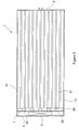
- is a sectional plain view of the refrigeration container in
Figure 1 . - A refrigeration transport container (1), in this embodiment a shipping container, is shown in
Figures 1 to 3 and includes a refrigeration unit (3) located at one end (5) behind a panel (7) opposite the doors (9). The panel (7) extends parallel to the end (5) between the sides (11) of the container (1) and is spaced apart from the top (13) and bottom (15) thereof to provide elongate openings (17, 19) which act as an air inlet and an air outlet respectively. A T-bar floor (21) is provided on the bottom (15) of the container and extends from the doors (9) to adjacent the air outlet (19). - The container described thus far is of conventional configuration.
- In accordance with the invention a barrier (25) is provided which extends between the sides (11) adjacent the air outlet (19). The barrier (25) extends from the bottom (15) of the container over the end of the T-bar floor (21) to the height of a standard pallet (27) (shown in broken lines in
Figure 2 ) above the T-bar floor (21). - A plurality of elongate stops (29), made in this embodiment from lengths of rectangular tubing, are secured to the panel (7) spaced apart from each other and extending generally upwardly. A plate (30) having the same thickness as the tubes extends across the upper ends of the stops (29) between the sides (11) of the container.
- The barrier (25) and stops (29) extend the same distance into the container from the panel (7).
- Furthermore, a passage (40) is provided internally along the top (13) of the container by, in this embodiment, a metal sheet which extends between the sides (11) from the air inlet (17) to near the doors (9). The passage (40) covers the air inlet (17) so that air is drawn through the passage into the inlet.
- In use, pallets (27) with produce (45) thereon are loaded into the container with the front of the first pallet abutting the barrier (25) and that of the produce abutting the stops (29). With the refrigeration unit (3) operational, air in the container is drawn through the open end of the passage (40), cooled and forced into the container once more through the outlet (19). The barrier (25) prevents the cooled air from flowing either along the T-bar floor (21) or through the aligned openings of the pallets (27). Instead, the cooled air is directed by the barrier (25) upwardly between the stops (29). The plate (30) prevents continued upward flow of the cooled air and which is thus forced to flow through the produce (45) until it is able to escape and return through the passage (40).
- The configuration of the container is highly effective in that the cooled air is immediately used to cool the produce and does not have an opportunity to short-circuit along the floor, sides or top of the container. Furthermore, the approximately 6m2 area of the panel (7) over which air is forced into the container is much smaller than the approximately 26m2 area of the floor and the air velocity is consequently much higher, again providing more efficient heat transfer. Still further, as the air is forced through the produce there is little opportunity for dead spots to form and homogenous cooling is thus achieved.
- It is calculated that the high degree of homogenous cooling achieved by the configuration of the container of the invention will result in a smaller temperature differential across the refrigeration unit as compared to conventional refrigerated containers and this has the result that the refrigeration unit will operate more effectively and thus use less energy.
- It is further envisaged that the elimination of hotspots and the reduction of the temperature differential across the refrigeration unit will result in an improved relative humidity of close to 95%. This in turn will enhance the quality of the produce and discourage deterioration thereof.
- As the container of the present invention does not require airflow along the floor or bottom of the container, and in fact prevents such flow, it is not necessary for the container to be provided with a T-bar floor. The T-bar floor could thus be eliminated, at least in part, and this can result in a saving of up to 750 kg in weight and an associated saving of the cost of materials and manufacturing.
- Existing refrigerated containers can easily be modified to incorporate the features of the invention, or refrigerated containers can be built to incorporate these features.
- It will be appreciated that many other embodiments of a refrigerated container exist which fall within the scope of the invention particularly as regards the configuration thereof. For example, the plate across the top of the stops can be bent to extend downwards towards the floor to aid mixing of the air. Also, any suitable stops can be used, including, for example, rubber extrusions. Furthermore, the inlet passage could have any suitable configuration and could, for example, include a number of tubes which could run between the inner and outer sides of the container.
Claims (7)
- A refrigeration transport container (1) having doors (9) at one end with a refrigeration unit (3) behind a panel (7) at the opposite end, and wherein the refrigeration (3) unit has a cold air outlet (19) adjacent the bottom (15) of the container (1) and an air inlet (17) adjacent the top (13) thereof, and wherein a barrier (25) extends upwardly from a floor (21) of the container provided on the bottom (15) thereof across the width of the container (1) adjacent the outlet (19) and is shaped to direct air from the outlet (19) upwardly such that air is discharged into the container (1) substantially above floor level, and the barrier further shaped to prevent movement of pallets on the floor (21) towards the outlet (19) and wherein the air inlet (17) draws air through a passage (40) which opens into the container (1) near the doors (9).
- A refrigeration transport container (1) as claimed in claim 1 wherein elongate spaced apart stops (29) are provided on the panel (7) extending in a generally upward direction.
- A refrigeration transport container (1) as claimed in claim 1 or 2 wherein the height of the barrier (25) is substantially the height of a pallet.
- A refrigeration transport container (1) as claimed in claim 2 wherein the stops (29) extend partway between the air inlet (17) and air outlet (19).
- A refrigeration transport container (1) as claimed in claim 4 wherein a plate (30) extends across the upper end of the stops (29) between the sides of the container (1).
- A refrigeration transport container (1) as claimed in any one of the preceding claims wherein the passage (40) extends along the top of the container (1) from the air inlet (17) to near the doors (9).
- A refrigeration transport container (1) as claimed in any one of the preceding claims wherein the passage (40) extends the width of the container (1).
Applications Claiming Priority (2)
| Application Number | Priority Date | Filing Date | Title |
|---|---|---|---|
| ZA201005552 | 2010-08-04 | ||
| PCT/IB2011/001811 WO2012017301A1 (en) | 2010-08-04 | 2011-08-04 | Refrigeration transport container |
Publications (3)
| Publication Number | Publication Date |
|---|---|
| EP2601115A1 EP2601115A1 (en) | 2013-06-12 |
| EP2601115A4 EP2601115A4 (en) | 2015-07-08 |
| EP2601115B1 true EP2601115B1 (en) | 2016-11-23 |
Family
ID=45558987
Family Applications (1)
| Application Number | Title | Priority Date | Filing Date |
|---|---|---|---|
| EP11814168.8A Not-in-force EP2601115B1 (en) | 2010-08-04 | 2011-08-04 | Refrigeration transport container |
Country Status (3)
| Country | Link |
|---|---|
| EP (1) | EP2601115B1 (en) |
| WO (1) | WO2012017301A1 (en) |
| ZA (1) | ZA201300411B (en) |
Cited By (1)
| Publication number | Priority date | Publication date | Assignee | Title |
|---|---|---|---|---|
| CN107246754A (en) * | 2017-06-22 | 2017-10-13 | 海信容声(广东)冷柜有限公司 | A kind of air-cooled horizontal refrigerator |
Families Citing this family (5)
| Publication number | Priority date | Publication date | Assignee | Title |
|---|---|---|---|---|
| CN208720605U (en) * | 2015-10-09 | 2019-04-09 | Ite株式会社 | System for maintaining refrigerated temperature in cold storage equipment |
| CN109230000A (en) * | 2018-09-04 | 2019-01-18 | 常州金坛鑫田农业科技有限公司 | A kind of fruits and vegetables dry fog fresh-preserving container |
| CN112274990B (en) * | 2020-11-02 | 2021-08-03 | 温岭市兴风食品有限公司 | A kind of fresh cold chain logistics preservation and transportation method |
| CN113803933A (en) * | 2021-09-30 | 2021-12-17 | 珠海格力电器股份有限公司 | refrigeration unit |
| CN118953905B (en) * | 2024-10-18 | 2024-12-17 | 坛墨质检科技股份有限公司 | Storage container for acetaldehyde solution standard substance |
Family Cites Families (8)
| Publication number | Priority date | Publication date | Assignee | Title |
|---|---|---|---|---|
| FR1490951A (en) * | 1966-08-30 | 1967-08-04 | Air conditioning process in a container for transporting cargo by road and sea | |
| DK362285D0 (en) | 1985-08-09 | 1985-08-09 | Kaj Plagborg | PROCEDURE FOR FREEZING OF GOODS PROVIDED TO A REGIONAL FREEZER STOCK AND PLANT FOR USE BY THE PROCEDURE |
| US5319941A (en) * | 1992-09-22 | 1994-06-14 | Trans-Pak, Inc. | System and method for storing perishable products in a refrigerated cargo bay |
| SE504556C2 (en) * | 1995-12-29 | 1997-03-03 | Frigotainer Ab | Cooling units for refrigeration containers |
| DE29720349U1 (en) * | 1997-11-17 | 1998-06-10 | Contrail GmbH, 21684 Stade | Containers for the transport of goods in a refrigerated cargo hold |
| US7578534B2 (en) * | 2005-11-03 | 2009-08-25 | Martin Marietta Materials, Inc. | Structural panel for a refrigerated trailer comprising an integrated bulkhead structure for promoting air flow |
| WO2007129280A1 (en) * | 2006-05-09 | 2007-11-15 | Perishable Products Export Control Board | Refrigerated container |
| CN102308165B (en) * | 2009-02-09 | 2014-06-18 | 开利公司 | Temperature distribution improvement in refrigerated container |
-
2011
- 2011-08-04 EP EP11814168.8A patent/EP2601115B1/en not_active Not-in-force
- 2011-08-04 WO PCT/IB2011/001811 patent/WO2012017301A1/en not_active Ceased
-
2013
- 2013-01-16 ZA ZA2013/00411A patent/ZA201300411B/en unknown
Cited By (1)
| Publication number | Priority date | Publication date | Assignee | Title |
|---|---|---|---|---|
| CN107246754A (en) * | 2017-06-22 | 2017-10-13 | 海信容声(广东)冷柜有限公司 | A kind of air-cooled horizontal refrigerator |
Also Published As
| Publication number | Publication date |
|---|---|
| EP2601115A4 (en) | 2015-07-08 |
| WO2012017301A1 (en) | 2012-02-09 |
| EP2601115A1 (en) | 2013-06-12 |
| ZA201300411B (en) | 2013-10-30 |
Similar Documents
| Publication | Publication Date | Title |
|---|---|---|
| WO2012017301A1 (en) | Refrigeration transport container | |
| US5946933A (en) | Refrigerated container with controlled air distribution | |
| US4879877A (en) | Air conditioning method and apparatus for refrigerated vehicles | |
| DE69533667T2 (en) | PALLET BASED COOLED TRANSPORT SYSTEM | |
| KR102319521B1 (en) | Refrigerated storage unit | |
| US5101643A (en) | Air conditioning method and apparatus for refrigerated vehicles | |
| HUT68606A (en) | Refrigerated container | |
| US4399737A (en) | Corrugated air return bulkhead | |
| WO2007129280A1 (en) | Refrigerated container | |
| CN1213352A (en) | Freezing container apparatus | |
| CN102548872A (en) | Temperature-controlled cargo container with air distribution | |
| US20070257040A1 (en) | Packaging for perishable goods | |
| US6543827B2 (en) | Climate controlled beverage truck | |
| CN105247303A (en) | Increased cargospace in a container | |
| US4351230A (en) | Self-venting cargo container | |
| US20120324912A1 (en) | Method for blast freezing a product | |
| US12576893B2 (en) | Refrigerated boxcar ducted floor | |
| US4936104A (en) | Air conditioning method and apparatus for refrigerated vehicles | |
| EP3094933B1 (en) | Apparatus and method for chilling or freezing | |
| CN103765135B (en) | Rapid freezing system and refrigeration appliance using the system | |
| CN102470981B (en) | Refrigerated container and method for integrating cargo box with refrigeration unit | |
| CN101889182A (en) | Container with air guide | |
| US6151908A (en) | Large-volume refrigerated shipping container | |
| US5533275A (en) | Method and apparatus for controlling the temperature of cargo within a container | |
| US20170191730A1 (en) | Adjustable height return air bulkhead |
Legal Events
| Date | Code | Title | Description |
|---|---|---|---|
| PUAI | Public reference made under article 153(3) epc to a published international application that has entered the european phase |
Free format text: ORIGINAL CODE: 0009012 |
|
| 17P | Request for examination filed |
Effective date: 20130204 |
|
| AK | Designated contracting states |
Kind code of ref document: A1 Designated state(s): AL AT BE BG CH CY CZ DE DK EE ES FI FR GB GR HR HU IE IS IT LI LT LU LV MC MK MT NL NO PL PT RO RS SE SI SK SM TR |
|
| DAX | Request for extension of the european patent (deleted) | ||
| REG | Reference to a national code |
Ref country code: DE Ref legal event code: R079 Ref document number: 602011032772 Country of ref document: DE Free format text: PREVIOUS MAIN CLASS: B65D0088000000 Ipc: B65D0088740000 |
|
| RA4 | Supplementary search report drawn up and despatched (corrected) |
Effective date: 20150608 |
|
| RIC1 | Information provided on ipc code assigned before grant |
Ipc: B65D 88/74 20060101AFI20150601BHEP Ipc: F25D 17/06 20060101ALI20150601BHEP |
|
| GRAP | Despatch of communication of intention to grant a patent |
Free format text: ORIGINAL CODE: EPIDOSNIGR1 |
|
| INTG | Intention to grant announced |
Effective date: 20160613 |
|
| GRAS | Grant fee paid |
Free format text: ORIGINAL CODE: EPIDOSNIGR3 |
|
| GRAA | (expected) grant |
Free format text: ORIGINAL CODE: 0009210 |
|
| AK | Designated contracting states |
Kind code of ref document: B1 Designated state(s): AL AT BE BG CH CY CZ DE DK EE ES FI FR GB GR HR HU IE IS IT LI LT LU LV MC MK MT NL NO PL PT RO RS SE SI SK SM TR |
|
| REG | Reference to a national code |
Ref country code: GB Ref legal event code: FG4D |
|
| REG | Reference to a national code |
Ref country code: CH Ref legal event code: EP |
|
| REG | Reference to a national code |
Ref country code: IE Ref legal event code: FG4D |
|
| REG | Reference to a national code |
Ref country code: AT Ref legal event code: REF Ref document number: 847675 Country of ref document: AT Kind code of ref document: T Effective date: 20161215 |
|
| REG | Reference to a national code |
Ref country code: DE Ref legal event code: R096 Ref document number: 602011032772 Country of ref document: DE |
|
| REG | Reference to a national code |
Ref country code: NL Ref legal event code: FP |
|
| PG25 | Lapsed in a contracting state [announced via postgrant information from national office to epo] |
Ref country code: LV Free format text: LAPSE BECAUSE OF FAILURE TO SUBMIT A TRANSLATION OF THE DESCRIPTION OR TO PAY THE FEE WITHIN THE PRESCRIBED TIME-LIMIT Effective date: 20161123 |
|
| REG | Reference to a national code |
Ref country code: LT Ref legal event code: MG4D |
|
| REG | Reference to a national code |
Ref country code: AT Ref legal event code: MK05 Ref document number: 847675 Country of ref document: AT Kind code of ref document: T Effective date: 20161123 |
|
| PG25 | Lapsed in a contracting state [announced via postgrant information from national office to epo] |
Ref country code: GR Free format text: LAPSE BECAUSE OF FAILURE TO SUBMIT A TRANSLATION OF THE DESCRIPTION OR TO PAY THE FEE WITHIN THE PRESCRIBED TIME-LIMIT Effective date: 20170224 Ref country code: LT Free format text: LAPSE BECAUSE OF FAILURE TO SUBMIT A TRANSLATION OF THE DESCRIPTION OR TO PAY THE FEE WITHIN THE PRESCRIBED TIME-LIMIT Effective date: 20161123 Ref country code: NO Free format text: LAPSE BECAUSE OF FAILURE TO SUBMIT A TRANSLATION OF THE DESCRIPTION OR TO PAY THE FEE WITHIN THE PRESCRIBED TIME-LIMIT Effective date: 20170223 Ref country code: SE Free format text: LAPSE BECAUSE OF FAILURE TO SUBMIT A TRANSLATION OF THE DESCRIPTION OR TO PAY THE FEE WITHIN THE PRESCRIBED TIME-LIMIT Effective date: 20161123 |
|
| PG25 | Lapsed in a contracting state [announced via postgrant information from national office to epo] |
Ref country code: AT Free format text: LAPSE BECAUSE OF FAILURE TO SUBMIT A TRANSLATION OF THE DESCRIPTION OR TO PAY THE FEE WITHIN THE PRESCRIBED TIME-LIMIT Effective date: 20161123 Ref country code: FI Free format text: LAPSE BECAUSE OF FAILURE TO SUBMIT A TRANSLATION OF THE DESCRIPTION OR TO PAY THE FEE WITHIN THE PRESCRIBED TIME-LIMIT Effective date: 20161123 Ref country code: PL Free format text: LAPSE BECAUSE OF FAILURE TO SUBMIT A TRANSLATION OF THE DESCRIPTION OR TO PAY THE FEE WITHIN THE PRESCRIBED TIME-LIMIT Effective date: 20161123 Ref country code: ES Free format text: LAPSE BECAUSE OF FAILURE TO SUBMIT A TRANSLATION OF THE DESCRIPTION OR TO PAY THE FEE WITHIN THE PRESCRIBED TIME-LIMIT Effective date: 20161123 Ref country code: HR Free format text: LAPSE BECAUSE OF FAILURE TO SUBMIT A TRANSLATION OF THE DESCRIPTION OR TO PAY THE FEE WITHIN THE PRESCRIBED TIME-LIMIT Effective date: 20161123 Ref country code: PT Free format text: LAPSE BECAUSE OF FAILURE TO SUBMIT A TRANSLATION OF THE DESCRIPTION OR TO PAY THE FEE WITHIN THE PRESCRIBED TIME-LIMIT Effective date: 20170323 Ref country code: RS Free format text: LAPSE BECAUSE OF FAILURE TO SUBMIT A TRANSLATION OF THE DESCRIPTION OR TO PAY THE FEE WITHIN THE PRESCRIBED TIME-LIMIT Effective date: 20161123 |
|
| PG25 | Lapsed in a contracting state [announced via postgrant information from national office to epo] |
Ref country code: RO Free format text: LAPSE BECAUSE OF FAILURE TO SUBMIT A TRANSLATION OF THE DESCRIPTION OR TO PAY THE FEE WITHIN THE PRESCRIBED TIME-LIMIT Effective date: 20161123 Ref country code: DK Free format text: LAPSE BECAUSE OF FAILURE TO SUBMIT A TRANSLATION OF THE DESCRIPTION OR TO PAY THE FEE WITHIN THE PRESCRIBED TIME-LIMIT Effective date: 20161123 Ref country code: EE Free format text: LAPSE BECAUSE OF FAILURE TO SUBMIT A TRANSLATION OF THE DESCRIPTION OR TO PAY THE FEE WITHIN THE PRESCRIBED TIME-LIMIT Effective date: 20161123 Ref country code: CZ Free format text: LAPSE BECAUSE OF FAILURE TO SUBMIT A TRANSLATION OF THE DESCRIPTION OR TO PAY THE FEE WITHIN THE PRESCRIBED TIME-LIMIT Effective date: 20161123 Ref country code: SK Free format text: LAPSE BECAUSE OF FAILURE TO SUBMIT A TRANSLATION OF THE DESCRIPTION OR TO PAY THE FEE WITHIN THE PRESCRIBED TIME-LIMIT Effective date: 20161123 |
|
| REG | Reference to a national code |
Ref country code: FR Ref legal event code: PLFP Year of fee payment: 7 |
|
| REG | Reference to a national code |
Ref country code: DE Ref legal event code: R097 Ref document number: 602011032772 Country of ref document: DE |
|
| PG25 | Lapsed in a contracting state [announced via postgrant information from national office to epo] |
Ref country code: BE Free format text: LAPSE BECAUSE OF FAILURE TO SUBMIT A TRANSLATION OF THE DESCRIPTION OR TO PAY THE FEE WITHIN THE PRESCRIBED TIME-LIMIT Effective date: 20161123 Ref country code: IT Free format text: LAPSE BECAUSE OF FAILURE TO SUBMIT A TRANSLATION OF THE DESCRIPTION OR TO PAY THE FEE WITHIN THE PRESCRIBED TIME-LIMIT Effective date: 20161123 Ref country code: SM Free format text: LAPSE BECAUSE OF FAILURE TO SUBMIT A TRANSLATION OF THE DESCRIPTION OR TO PAY THE FEE WITHIN THE PRESCRIBED TIME-LIMIT Effective date: 20161123 Ref country code: BG Free format text: LAPSE BECAUSE OF FAILURE TO SUBMIT A TRANSLATION OF THE DESCRIPTION OR TO PAY THE FEE WITHIN THE PRESCRIBED TIME-LIMIT Effective date: 20170223 |
|
| PLBE | No opposition filed within time limit |
Free format text: ORIGINAL CODE: 0009261 |
|
| STAA | Information on the status of an ep patent application or granted ep patent |
Free format text: STATUS: NO OPPOSITION FILED WITHIN TIME LIMIT |
|
| 26N | No opposition filed |
Effective date: 20170824 |
|
| PG25 | Lapsed in a contracting state [announced via postgrant information from national office to epo] |
Ref country code: SI Free format text: LAPSE BECAUSE OF FAILURE TO SUBMIT A TRANSLATION OF THE DESCRIPTION OR TO PAY THE FEE WITHIN THE PRESCRIBED TIME-LIMIT Effective date: 20161123 |
|
| REG | Reference to a national code |
Ref country code: CH Ref legal event code: PL |
|
| PG25 | Lapsed in a contracting state [announced via postgrant information from national office to epo] |
Ref country code: MC Free format text: LAPSE BECAUSE OF FAILURE TO SUBMIT A TRANSLATION OF THE DESCRIPTION OR TO PAY THE FEE WITHIN THE PRESCRIBED TIME-LIMIT Effective date: 20161123 |
|
| GBPC | Gb: european patent ceased through non-payment of renewal fee |
Effective date: 20170804 |
|
| PG25 | Lapsed in a contracting state [announced via postgrant information from national office to epo] |
Ref country code: CH Free format text: LAPSE BECAUSE OF NON-PAYMENT OF DUE FEES Effective date: 20170831 Ref country code: LI Free format text: LAPSE BECAUSE OF NON-PAYMENT OF DUE FEES Effective date: 20170831 |
|
| REG | Reference to a national code |
Ref country code: IE Ref legal event code: MM4A |
|
| PG25 | Lapsed in a contracting state [announced via postgrant information from national office to epo] |
Ref country code: LU Free format text: LAPSE BECAUSE OF NON-PAYMENT OF DUE FEES Effective date: 20170804 |
|
| PG25 | Lapsed in a contracting state [announced via postgrant information from national office to epo] |
Ref country code: GB Free format text: LAPSE BECAUSE OF NON-PAYMENT OF DUE FEES Effective date: 20170804 Ref country code: IE Free format text: LAPSE BECAUSE OF NON-PAYMENT OF DUE FEES Effective date: 20170804 |
|
| REG | Reference to a national code |
Ref country code: FR Ref legal event code: PLFP Year of fee payment: 8 |
|
| PG25 | Lapsed in a contracting state [announced via postgrant information from national office to epo] |
Ref country code: MT Free format text: LAPSE BECAUSE OF NON-PAYMENT OF DUE FEES Effective date: 20170804 |
|
| PG25 | Lapsed in a contracting state [announced via postgrant information from national office to epo] |
Ref country code: HU Free format text: LAPSE BECAUSE OF FAILURE TO SUBMIT A TRANSLATION OF THE DESCRIPTION OR TO PAY THE FEE WITHIN THE PRESCRIBED TIME-LIMIT; INVALID AB INITIO Effective date: 20110804 |
|
| PG25 | Lapsed in a contracting state [announced via postgrant information from national office to epo] |
Ref country code: CY Free format text: LAPSE BECAUSE OF NON-PAYMENT OF DUE FEES Effective date: 20161123 |
|
| PG25 | Lapsed in a contracting state [announced via postgrant information from national office to epo] |
Ref country code: MK Free format text: LAPSE BECAUSE OF FAILURE TO SUBMIT A TRANSLATION OF THE DESCRIPTION OR TO PAY THE FEE WITHIN THE PRESCRIBED TIME-LIMIT Effective date: 20161123 |
|
| PG25 | Lapsed in a contracting state [announced via postgrant information from national office to epo] |
Ref country code: TR Free format text: LAPSE BECAUSE OF FAILURE TO SUBMIT A TRANSLATION OF THE DESCRIPTION OR TO PAY THE FEE WITHIN THE PRESCRIBED TIME-LIMIT Effective date: 20161123 |
|
| PG25 | Lapsed in a contracting state [announced via postgrant information from national office to epo] |
Ref country code: AL Free format text: LAPSE BECAUSE OF FAILURE TO SUBMIT A TRANSLATION OF THE DESCRIPTION OR TO PAY THE FEE WITHIN THE PRESCRIBED TIME-LIMIT Effective date: 20161123 Ref country code: IS Free format text: LAPSE BECAUSE OF FAILURE TO SUBMIT A TRANSLATION OF THE DESCRIPTION OR TO PAY THE FEE WITHIN THE PRESCRIBED TIME-LIMIT Effective date: 20170323 |
|
| PGFP | Annual fee paid to national office [announced via postgrant information from national office to epo] |
Ref country code: NL Payment date: 20200820 Year of fee payment: 10 |
|
| PGFP | Annual fee paid to national office [announced via postgrant information from national office to epo] |
Ref country code: DE Payment date: 20200819 Year of fee payment: 10 Ref country code: FR Payment date: 20200819 Year of fee payment: 10 |
|
| REG | Reference to a national code |
Ref country code: DE Ref legal event code: R119 Ref document number: 602011032772 Country of ref document: DE |
|
| REG | Reference to a national code |
Ref country code: NL Ref legal event code: MM Effective date: 20210901 |
|
| PG25 | Lapsed in a contracting state [announced via postgrant information from national office to epo] |
Ref country code: NL Free format text: LAPSE BECAUSE OF NON-PAYMENT OF DUE FEES Effective date: 20210901 |
|
| PG25 | Lapsed in a contracting state [announced via postgrant information from national office to epo] |
Ref country code: FR Free format text: LAPSE BECAUSE OF NON-PAYMENT OF DUE FEES Effective date: 20210831 Ref country code: DE Free format text: LAPSE BECAUSE OF NON-PAYMENT OF DUE FEES Effective date: 20220301 |