EP2601080B1 - Bumper assembly - Google Patents
Bumper assembly Download PDFInfo
- Publication number
- EP2601080B1 EP2601080B1 EP11767906.8A EP11767906A EP2601080B1 EP 2601080 B1 EP2601080 B1 EP 2601080B1 EP 11767906 A EP11767906 A EP 11767906A EP 2601080 B1 EP2601080 B1 EP 2601080B1
- Authority
- EP
- European Patent Office
- Prior art keywords
- box
- shell
- crash
- beam portion
- crash box
- Prior art date
- Legal status (The legal status is an assumption and is not a legal conclusion. Google has not performed a legal analysis and makes no representation as to the accuracy of the status listed.)
- Not-in-force
Links
- 238000000034 method Methods 0.000 claims description 29
- 229910052751 metal Inorganic materials 0.000 claims description 27
- 239000002184 metal Substances 0.000 claims description 27
- 230000008569 process Effects 0.000 claims description 14
- 238000001816 cooling Methods 0.000 claims description 11
- 238000010438 heat treatment Methods 0.000 claims description 7
- 229910000734 martensite Inorganic materials 0.000 claims description 7
- 238000004519 manufacturing process Methods 0.000 claims description 5
- 230000008878 coupling Effects 0.000 claims description 4
- 238000010168 coupling process Methods 0.000 claims description 4
- 238000005859 coupling reaction Methods 0.000 claims description 4
- 238000005304 joining Methods 0.000 claims description 4
- 238000004026 adhesive bonding Methods 0.000 claims description 3
- 239000000463 material Substances 0.000 description 6
- 238000003466 welding Methods 0.000 description 6
- 229910000831 Steel Inorganic materials 0.000 description 4
- 238000010586 diagram Methods 0.000 description 4
- 239000010959 steel Substances 0.000 description 4
- 238000007493 shaping process Methods 0.000 description 3
- 229910000712 Boron steel Inorganic materials 0.000 description 2
- 239000011324 bead Substances 0.000 description 2
- 239000006260 foam Substances 0.000 description 2
- 239000011261 inert gas Substances 0.000 description 2
- 238000003825 pressing Methods 0.000 description 2
- 238000005496 tempering Methods 0.000 description 2
- 230000007704 transition Effects 0.000 description 2
- 229910052782 aluminium Inorganic materials 0.000 description 1
- XAGFODPZIPBFFR-UHFFFAOYSA-N aluminium Chemical compound [Al] XAGFODPZIPBFFR-UHFFFAOYSA-N 0.000 description 1
- 230000008859 change Effects 0.000 description 1
- 230000001419 dependent effect Effects 0.000 description 1
- 230000001939 inductive effect Effects 0.000 description 1
- 239000007769 metal material Substances 0.000 description 1
- 230000004048 modification Effects 0.000 description 1
- 238000012986 modification Methods 0.000 description 1
- 230000002093 peripheral effect Effects 0.000 description 1
- 230000008439 repair process Effects 0.000 description 1
Images


Classifications
-
- B—PERFORMING OPERATIONS; TRANSPORTING
- B60—VEHICLES IN GENERAL
- B60R—VEHICLES, VEHICLE FITTINGS, OR VEHICLE PARTS, NOT OTHERWISE PROVIDED FOR
- B60R19/00—Wheel guards; Radiator guards, e.g. grilles; Obstruction removers; Fittings damping bouncing force in collisions
- B60R19/02—Bumpers, i.e. impact receiving or absorbing members for protecting vehicles or fending off blows from other vehicles or objects
- B60R19/24—Arrangements for mounting bumpers on vehicles
- B60R19/26—Arrangements for mounting bumpers on vehicles comprising yieldable mounting means
- B60R19/34—Arrangements for mounting bumpers on vehicles comprising yieldable mounting means destroyed upon impact, e.g. one-shot type
-
- B—PERFORMING OPERATIONS; TRANSPORTING
- B21—MECHANICAL METAL-WORKING WITHOUT ESSENTIALLY REMOVING MATERIAL; PUNCHING METAL
- B21D—WORKING OR PROCESSING OF SHEET METAL OR METAL TUBES, RODS OR PROFILES WITHOUT ESSENTIALLY REMOVING MATERIAL; PUNCHING METAL
- B21D53/00—Making other particular articles
- B21D53/88—Making other particular articles other parts for vehicles, e.g. cowlings, mudguards
-
- B—PERFORMING OPERATIONS; TRANSPORTING
- B60—VEHICLES IN GENERAL
- B60R—VEHICLES, VEHICLE FITTINGS, OR VEHICLE PARTS, NOT OTHERWISE PROVIDED FOR
- B60R19/00—Wheel guards; Radiator guards, e.g. grilles; Obstruction removers; Fittings damping bouncing force in collisions
- B60R19/02—Bumpers, i.e. impact receiving or absorbing members for protecting vehicles or fending off blows from other vehicles or objects
- B60R19/03—Bumpers, i.e. impact receiving or absorbing members for protecting vehicles or fending off blows from other vehicles or objects characterised by material, e.g. composite
-
- B—PERFORMING OPERATIONS; TRANSPORTING
- B60—VEHICLES IN GENERAL
- B60R—VEHICLES, VEHICLE FITTINGS, OR VEHICLE PARTS, NOT OTHERWISE PROVIDED FOR
- B60R19/00—Wheel guards; Radiator guards, e.g. grilles; Obstruction removers; Fittings damping bouncing force in collisions
- B60R19/02—Bumpers, i.e. impact receiving or absorbing members for protecting vehicles or fending off blows from other vehicles or objects
- B60R19/18—Bumpers, i.e. impact receiving or absorbing members for protecting vehicles or fending off blows from other vehicles or objects characterised by the cross-section; Means within the bumper to absorb impact
-
- B—PERFORMING OPERATIONS; TRANSPORTING
- B62—LAND VEHICLES FOR TRAVELLING OTHERWISE THAN ON RAILS
- B62D—MOTOR VEHICLES; TRAILERS
- B62D21/00—Understructures, i.e. chassis frame on which a vehicle body may be mounted
- B62D21/15—Understructures, i.e. chassis frame on which a vehicle body may be mounted having impact absorbing means, e.g. a frame designed to permanently or temporarily change shape or dimension upon impact with another body
-
- B—PERFORMING OPERATIONS; TRANSPORTING
- B21—MECHANICAL METAL-WORKING WITHOUT ESSENTIALLY REMOVING MATERIAL; PUNCHING METAL
- B21D—WORKING OR PROCESSING OF SHEET METAL OR METAL TUBES, RODS OR PROFILES WITHOUT ESSENTIALLY REMOVING MATERIAL; PUNCHING METAL
- B21D22/00—Shaping without cutting, by stamping, spinning, or deep-drawing
- B21D22/02—Stamping using rigid devices or tools
- B21D22/022—Stamping using rigid devices or tools by heating the blank or stamping associated with heat treatment
-
- B—PERFORMING OPERATIONS; TRANSPORTING
- B21—MECHANICAL METAL-WORKING WITHOUT ESSENTIALLY REMOVING MATERIAL; PUNCHING METAL
- B21D—WORKING OR PROCESSING OF SHEET METAL OR METAL TUBES, RODS OR PROFILES WITHOUT ESSENTIALLY REMOVING MATERIAL; PUNCHING METAL
- B21D37/00—Tools as parts of machines covered by this subclass
- B21D37/16—Heating or cooling
-
- B—PERFORMING OPERATIONS; TRANSPORTING
- B60—VEHICLES IN GENERAL
- B60R—VEHICLES, VEHICLE FITTINGS, OR VEHICLE PARTS, NOT OTHERWISE PROVIDED FOR
- B60R19/00—Wheel guards; Radiator guards, e.g. grilles; Obstruction removers; Fittings damping bouncing force in collisions
- B60R19/02—Bumpers, i.e. impact receiving or absorbing members for protecting vehicles or fending off blows from other vehicles or objects
- B60R19/24—Arrangements for mounting bumpers on vehicles
- B60R19/26—Arrangements for mounting bumpers on vehicles comprising yieldable mounting means
-
- B—PERFORMING OPERATIONS; TRANSPORTING
- B60—VEHICLES IN GENERAL
- B60R—VEHICLES, VEHICLE FITTINGS, OR VEHICLE PARTS, NOT OTHERWISE PROVIDED FOR
- B60R19/00—Wheel guards; Radiator guards, e.g. grilles; Obstruction removers; Fittings damping bouncing force in collisions
- B60R19/02—Bumpers, i.e. impact receiving or absorbing members for protecting vehicles or fending off blows from other vehicles or objects
- B60R19/18—Bumpers, i.e. impact receiving or absorbing members for protecting vehicles or fending off blows from other vehicles or objects characterised by the cross-section; Means within the bumper to absorb impact
- B60R2019/1806—Structural beams therefor, e.g. shock-absorbing
- B60R2019/1813—Structural beams therefor, e.g. shock-absorbing made of metal
- B60R2019/182—Structural beams therefor, e.g. shock-absorbing made of metal of light metal, e.g. extruded
-
- B—PERFORMING OPERATIONS; TRANSPORTING
- B60—VEHICLES IN GENERAL
- B60R—VEHICLES, VEHICLE FITTINGS, OR VEHICLE PARTS, NOT OTHERWISE PROVIDED FOR
- B60R19/00—Wheel guards; Radiator guards, e.g. grilles; Obstruction removers; Fittings damping bouncing force in collisions
- B60R19/02—Bumpers, i.e. impact receiving or absorbing members for protecting vehicles or fending off blows from other vehicles or objects
- B60R19/18—Bumpers, i.e. impact receiving or absorbing members for protecting vehicles or fending off blows from other vehicles or objects characterised by the cross-section; Means within the bumper to absorb impact
- B60R2019/1806—Structural beams therefor, e.g. shock-absorbing
- B60R2019/1813—Structural beams therefor, e.g. shock-absorbing made of metal
- B60R2019/1826—Structural beams therefor, e.g. shock-absorbing made of metal of high-tension steel
-
- C—CHEMISTRY; METALLURGY
- C21—METALLURGY OF IRON
- C21D—MODIFYING THE PHYSICAL STRUCTURE OF FERROUS METALS; GENERAL DEVICES FOR HEAT TREATMENT OF FERROUS OR NON-FERROUS METALS OR ALLOYS; MAKING METAL MALLEABLE, e.g. BY DECARBURISATION OR TEMPERING
- C21D1/00—General methods or devices for heat treatment, e.g. annealing, hardening, quenching or tempering
- C21D1/62—Quenching devices
- C21D1/673—Quenching devices for die quenching
-
- C—CHEMISTRY; METALLURGY
- C21—METALLURGY OF IRON
- C21D—MODIFYING THE PHYSICAL STRUCTURE OF FERROUS METALS; GENERAL DEVICES FOR HEAT TREATMENT OF FERROUS OR NON-FERROUS METALS OR ALLOYS; MAKING METAL MALLEABLE, e.g. BY DECARBURISATION OR TEMPERING
- C21D8/00—Modifying the physical properties by deformation combined with, or followed by, heat treatment
- C21D8/02—Modifying the physical properties by deformation combined with, or followed by, heat treatment during manufacturing of plates or strips
- C21D8/0221—Modifying the physical properties by deformation combined with, or followed by, heat treatment during manufacturing of plates or strips characterised by the working steps
-
- C—CHEMISTRY; METALLURGY
- C21—METALLURGY OF IRON
- C21D—MODIFYING THE PHYSICAL STRUCTURE OF FERROUS METALS; GENERAL DEVICES FOR HEAT TREATMENT OF FERROUS OR NON-FERROUS METALS OR ALLOYS; MAKING METAL MALLEABLE, e.g. BY DECARBURISATION OR TEMPERING
- C21D8/00—Modifying the physical properties by deformation combined with, or followed by, heat treatment
- C21D8/02—Modifying the physical properties by deformation combined with, or followed by, heat treatment during manufacturing of plates or strips
- C21D8/0294—Modifying the physical properties by deformation combined with, or followed by, heat treatment during manufacturing of plates or strips involving a localised treatment
-
- C—CHEMISTRY; METALLURGY
- C21—METALLURGY OF IRON
- C21D—MODIFYING THE PHYSICAL STRUCTURE OF FERROUS METALS; GENERAL DEVICES FOR HEAT TREATMENT OF FERROUS OR NON-FERROUS METALS OR ALLOYS; MAKING METAL MALLEABLE, e.g. BY DECARBURISATION OR TEMPERING
- C21D9/00—Heat treatment, e.g. annealing, hardening, quenching or tempering, adapted for particular articles; Furnaces therefor
- C21D9/46—Heat treatment, e.g. annealing, hardening, quenching or tempering, adapted for particular articles; Furnaces therefor for sheet metals
-
- Y—GENERAL TAGGING OF NEW TECHNOLOGICAL DEVELOPMENTS; GENERAL TAGGING OF CROSS-SECTIONAL TECHNOLOGIES SPANNING OVER SEVERAL SECTIONS OF THE IPC; TECHNICAL SUBJECTS COVERED BY FORMER USPC CROSS-REFERENCE ART COLLECTIONS [XRACs] AND DIGESTS
- Y10—TECHNICAL SUBJECTS COVERED BY FORMER USPC
- Y10T—TECHNICAL SUBJECTS COVERED BY FORMER US CLASSIFICATION
- Y10T29/00—Metal working
- Y10T29/49—Method of mechanical manufacture
- Y10T29/49616—Structural member making
- Y10T29/49622—Vehicular structural member making
-
- Y—GENERAL TAGGING OF NEW TECHNOLOGICAL DEVELOPMENTS; GENERAL TAGGING OF CROSS-SECTIONAL TECHNOLOGIES SPANNING OVER SEVERAL SECTIONS OF THE IPC; TECHNICAL SUBJECTS COVERED BY FORMER USPC CROSS-REFERENCE ART COLLECTIONS [XRACs] AND DIGESTS
- Y10—TECHNICAL SUBJECTS COVERED BY FORMER USPC
- Y10T—TECHNICAL SUBJECTS COVERED BY FORMER US CLASSIFICATION
- Y10T29/00—Metal working
- Y10T29/49—Method of mechanical manufacture
- Y10T29/49826—Assembling or joining
Definitions
- the present invention relates to a method of making a beam-box crash management system according to the preamble of claim 1. Further a beam-box crash management system according to the preamble of claim 6 is provided.
- a generic method is known from EP 2025560 A1 . Said document discloses different methods for hardening a beam portion of a beam-box crash management system, wherein the yield strengths of crash box portions integrally formed with the beam portion is reduced.
- the beam-box crash management system of EP 2025560 A1 has a U-formed geometry wherein one open face faces the frame way of a rail of a vehicle.
- Automobiles are equipped with bumpers, which are attached to either end thereof to absorb impact in a collision and limit as far as possible any damage to parts of the vehicle.
- bumpers In order to minimize damage to vehicles during low speed impacts, such as for instance less than about 15-16 km/h, car manufacturers provide "sacrificial elements" known as crash boxes, which in the event of impact cushions most of the impact energy, being deformed but preventing deformation of the vehicle chassis. In fact, any deformation of the vehicle chassis results in high repair costs, leading to unacceptably high insurance premiums, etc.
- a bumper assembly with a sacrificial element comprises a pair of crash boxes, a cross member, a cushioning element such as foam or the like, and a bumper shield.
- the two crash boxes are fixed to the ends of two respective longitudinal members of the vehicle chassis via two respective plates.
- the cross member is joined to the opposite side of the crash boxes and extends continuously from one crash box to the other.
- the cushioning element made of foam or the like, typically, is constrained to the outside of the cross member.
- a bumper shield having primarily aesthetic and aerodynamic functions, covers the bumper assembly.
- both the crash boxes and the cross member are made of metallic materials, such as for instance steel or aluminum.
- the prior art solution, with metal crash boxes, cross members and plates for fixing the crash boxes to the vehicle, are considered to be somewhat awkward to assemble, heavy, costly and not easily adaptable to new vehicle models.
- a further beam-box crash management system is also known from EP 0730908 A2 .
- a method of making a beam-box crash management system comprising: forming a first shell from a first sheet metal blank by a hot forming process, the first shell having a high tensile strength beam portion and integrally formed therewith a first low yield strength crash box portion proximate a first end of the beam portion and a second low yield strength crash box portion proximate a second end of the beam portion, the first shell having an open face extending continuously along the beam portion and each of the first and second crash box portions; forming a closing element from a second sheet metal blank; and, fixedly securing the closing element adjacent to the open face of the first shell.
- amethod of making a beam-box crash management system comprising: heating a first sheet metal blank to at least an austenitizing temperature of the metal; hot forming the austenitic blank in a pair of cooled tools to form a first one piece beam-box component having a generally three-sided channel structure with one open side; during the hot forming process, cooling a beam portion of the formed component at a first rate that is sufficiently rapid to harden the beam portion into an essentially martensitic structure with a tensile strength of between about 1300 N/mm 2 and about 1600 N/mm 2 , and cooling crash box portions of the formed component at a second rate that is slower than the first rate, such that the crash box portions achieve a yield strength of between approximately 200 N/mm 2 and 450 N/mm 2 ; forming a closing element from a second sheet metal blank; and, fixedly securing the closing element along the open side of the first one piece beam-box component.
- a beam-box crash management system comprising: a first one piece shell having a high tensile strength beam portion and integrally formed therewith a first low yield strength crash box portion proximate a first end of the beam portion and a second low yield strength crash box portion proximate a second end of the beam portion, the first one piece shell having an open face extending continuously along the beam portion and each of the first and second crash box portions; and, a closing element fixedly secured adjacent to the open face of the first one piece shell.
- abeam-box crash management system comprising: a first beam-box shell, fabricated from a first sheet metal blank, having a high tensile strength beam portion and integrally formed therewith a first low yield strength crash box portion proximate a first end of the beam portion and a second low yield crash box portion proximate a second end of the beam portion, the first end being opposite the second end, and the first beam-box shell having one open side defining a first rim; a second beam-box shell, fabricated from a second sheet metal blank, having a high tensile strength beam portion and integrally formed therewith a first low yield strength crash box structure proximate a first end of the beam portion and a second low strength crash box structure proximate the second end of the beam portion, the first end being opposite the second end, and the second beam-box shell having one open side defining a second rim; wherein the first beam-box shell is fixedly secured to the second beam-box shell such
- the crash management system comprises a first shell 100a and a second shell 100b.
- the first shell 100a is formed from a first sheet metal blank and the second shell 100b is formed separately from a second sheet metal blank.
- the first and second sheet metal blanks each comprise 22MnB5 boron steel. More particularly, the first shell 100a and the second shell 100b are formed using a tailored tempering hot forming process, as is described in greater detail in the following sections.
- the first shell 100a comprises a high tensile strength beam portion 102a. Integrally formed with the beam portion 102a is a first low yield strength crash box portion 104a proximate a first end of the beam portion and a second low yield strength crash box portion 106a proximate a second end of the beam portion, the second end being opposite the first end. Similarly, the second shell 100b comprises a high tensile strength beam portion 102b. Integrally formed with the beam portion 102b is a first low yield strength crash box portion 104b proximate a first end of the beam portion and a second low yield strength crash box portion 106b proximate a second end of the beam portion, the second end being opposite the first end.
- a typical value of the tensile strength of the beam portions 102a and 102b is between about 1300 N/mm 2 and about 1600 N/mm 2 .
- a typical value of the yield strength of the first and second crash box portions 104a/b and 106a/b, respectively, is between about 200 N/mm 2 and about 450 N/mm 2 .
- the yield strength of the crash box portions is adjustable during the hot forming process, to achieve desired values depending upon performance requirements. Due to the nature of the hot forming process that is used to form the first shell 100a and the second shell 100b, a transition zone exists between the high tensile strength material of the beam portion 102a/b and the low yield strength material of the first and second crash box portions 104a/b and 106a/b.
- the first shell 100a is a unitary component having a generally three-sided channel structure with one open side.
- a top surface 200a of the first shell 100a extends into two opposite sidewalls 202a and 204b.
- the edges of the two opposite sidewalls along the open side of the first shell define a first rim 108a.
- the second shell 100b is also a unitary component having a generally three-sided channel structure with one open side.
- a bottom surface 200b of the second shell 100b extends into two opposite sidewalls 202b and 204b.
- the edges of the two opposite sidewalls 202b and 204b along the open side of the first shell define a second rim 108b.
- the second rim 108b is shaped to nest inside the first rim 108a when the first shell 100a is fixedly secured to the second shell 100b.
- the generally three-sided channel structures extend the length of the beam portions 102a and 102b, and through the first and second crash box portions 104a/b and 106a/b, respectively.
- top and “bottom” as used herein are defined in the context of FIG. 2 , and that they are not intended to imply any required orientation of the crash management system when in an installed condition.
- first and second crash box portions 104a/b and 106a/b are formed with "beads" (not shown) to optimize folding behavior during an impact.
- a method of making the crash management system of FIG. 1 includes heating the first blank of flat sheet steel in a furnace to austenitic state, moving the first blank into a cooled pair of shaping tools, and then pressing the hot first blank into the shape of the first shell 100a.
- the shaped first shell 100a is maintained in the tools until the beam portion 102a has hardened into an essentially martensitic structure with a tensile strength of between about 1300 N/mm 2 and about 1600 N/mm 2 .
- first and second crash box portions 104a and 106a are maintained at such a temperature that the first and second crash box portions 104a and 106a, respectively, are prevented from rapid cooling and will reach only a yield strength of between about 200 N/mm 2 and about 450 N/mm 2 .
- heat is added (e.g., using cartridge heaters) to the portion of each tool adjacent the first and second crash box portions 104a and 106a, respectively, and/or the portion of each tool adjacent the first and second crash box portions 104a and 106a, respectively, is insulated such that the rate of heat loss from said crash box portions is reduced relative to the rate of heat loss of non-insulated portions.
- the second blank of flat sheet steel is heated in a furnace to austenitic state, is moved into a cooled pair of shaping tools, and is pressed while still hot first into the shape of the second shell 100b.
- the shaped second shell 100b is maintained in the tools until the beam portion 102b has hardened into an essentially martensitic structure with a tensile strength of between about 1300 N/mm 2 and about 1600 N/mm 2 .
- each tool adjacent the first and second crash box portions 104b and 106b, respectively is maintained at such a temperature that the first and second crash box portions 104b and 106b, respectively, are prevented from rapid cooling and will reach only a yield strength of between about 200 N/mm 2 and about 450 N/mm 2 .
- heat is added (e.g., using cartridge heaters) to the portion of each tool adjacent the first and second crash box portions 104b and 106b, respectively, and/or the portion of each tool adjacent the first and second crash box portions 104b and 106b, respectively, is insulated such that the rate of heat loss from said crash box portions is reduced relative to the rate of heat loss of non-insulated portions.
- first shell 100a and second shell 100b are aligned one with the other and then fixedly secured together.
- Some non-limiting techniques for fixedly securing the first shell 100a to the second shell 100b include: thermal joining (such as for instance spot welding, metal inert gas (MIG) welding, laser welding, etc.); adhesive bonding; and, mechanical coupling (such as for instance clinching or riveting).
- the second shell 100b is a closing element that is fixedly secured to the first shell 100a.
- the crash management system comprises a one-piece shell 300 that is formed from a first sheet metal blank, and a not illustrated closing element.
- the first sheet metal blanks comprises 22MnB5 boron steel.
- the one-piece shell 300 is formed using a tailored tempering hot forming process, as is described in greater detail in the following sections.
- the one-piece shell 300 comprises a high tensile strength beam portion 302. Integrally formed with the beam portion 302 is a first low yield strength crash box portion 304 proximate a first end of the beam portion and a second low yield strength crash box portion 306 proximate a second end of the beam portion, the second end being opposite the first end.
- a typical value of the tensile strength of the beam portion 302 is between about 1300 N/mm 2 and about 1600 N/mm 2 .
- a typical value of the yield strength of the first and second crash box portions 304 and 306, respectively, is between about 200 N/mm 2 and about 450 N/mm 2 .
- the yield strength of the crash box portions is adjustable during the hot forming process, to achieve desired values depending upon performance requirements. Due to the nature of the hot forming process that is used to form the one-piece shell 300, a transition zone exists between the high tensile strength material of the beam portion 300 and the low yield strength material of the first and second crash box portions 304 and 306.
- FIG. 4a shown is a rear perspective view of the crash management system of FIG. 3 . Also shown in FIG. 4a is the closing element 400.
- the one-piece shell 300 is a unitary component having a generally three-sided channel structure with one open side.
- a top surface 402 of the one-piece shell 300 extends into two opposite sidewalls 404 and 406.
- the edges of the two opposite sidewalls along the open side of the first shell define a rim 408.
- the generally three-sided channel structure extends the length of the beam portion 302, and through the first and second crash box portions 304 and 306.
- the closing element 400 has a peripheral flange 410 for use in fixedly securing the closing element 400 to the rim 408 of the one-piece shell 300.
- top as used herein is defined in the context of FIG. 4 , and that it is not intended to imply any required orientation of the crash management system when in an installed condition.
- FIG. 4c shown is an enlarged detail view of a portion of FIG. 4a lying within the other dashed-line circle.
- FIG. 4c shows that the corner between the crash boxes and the beam portion may optionally be notched out (notch 412), for formability reasons.
- first and second crash box portions 304 and 306 are formed with "beads" (not shown) to optimize folding behavior during an impact.
- a method of making the crash management system of FIG. 3 includes heating the first blank of flat sheet steel in a furnace to austenitic state, moving the first blank into a cooled pair of shaping tools, and then pressing the hot first blank into the shape of the one-piece shell 300.
- the shaped one-piece shell 300 is maintained in the tools until the beam portion 302 has hardened into an essentially martensitic structure with a tensile strength of between about 1300 N/mm 2 and about 1600 N/mm 2 .
- a portion of each tool adjacent the first and second crash box portions 304 and 306, respectively is maintained at such a temperature that the first and second crash box portions 304 and 306, respectively, are prevented from rapid cooling and will reach only a yield strength of between about 200 N/mm 2 and about 450 N/mm 2 .
- heat is added (e.g., using cartridge heaters) to the portion of each tool adjacent the first and second crash box portions 304 and 306, respectively, and/or the portion of each tool adjacent the first and second crash box portions 304 and 306, respectively, is insulated such that the rate of heat loss from said crash box portions is reduced relative to the rate of heat loss of non-insulated portions.
- the closing element 400 is separately shaped.
- the flange 410 of the closing element 400 is then aligned with the rim 408 along the open side of the one-piece shell 300, and the closing element 400 is fixedly secured to the one-piece shell 300.
- Some non-limiting techniques for fixedly securing the one-piece shell 300 to the closing element include: thermal joining (such as for instance spot welding, metal inert gas (MIG) welding, laser welding, etc.); adhesive bonding; and, mechanical coupling (such as for instance clinching or riveting).
- a first shell is formed from a first sheet metal blank by a hot forming process, the first shell having a high tensile strength beam portion and integrally formed therewith a first low yield strength crash box portion proximate a first end of the beam portion and a second low yield strength crash box portion proximate a second end of the beam portion, the first shell having an open face extending continuously along the beam portion and each of the first and second crash box portions.
- a closing element is formed from a second sheet metal blank.
- the closing element is fixedly secured adjacent to the open face of the first shell.
- a first sheet metal blank is heated to at least an austenitizing temperature of the metal.
- the austenitic blank is hot formed in a pair of cooled tools to form a first one-piece beam-box component having a generally three-sided channel structure with one open side.
- a beam portion of the formed component is cooled at a first rate that is sufficiently rapid to harden the beam portion into an essentially martensitic structure with a tensile strength of between about 1300 N/mm 2 and about 1600 N/mm 2 , and crash box portions of the formed component are cooled at a second rate that is slower than the first rate, such that the crash box portions achieve a yield strength of between approximately 200 N/mm 2 and 450 N/mm 2 .
- a closing element is formed from a second sheet metal blank. At 608 the closing element is fixedly secured along the open side of the first one-piece beam-box component.
- a blank is heated uniformly to austenitic state and selected portions are cooled at a rate during forming, which results in lower strength in said selected portions relative to other portions.
- selected portions are either shielded from heating or kept in a lower temperature environment (e.g., external to a furnace or within a cooler furnace portion) such that the austenitizirig temperature of the material in said selected portions is not exceeded.
- the blank is formed and selected portions are heated subsequently (e.g., by inductive heating) to austenitic state and then rapidly cooled to achieve high strength in said selected portions.
- the entire component is formed with rapid cooling, and subsequently selected portions are heated to a temperature that is sufficiently high to induce a phase change in said selected portions, followed by controlled cooling at a rate that results in a softening of the material in said selected portions relative to the non-heated portions.
- yield strengths of the first and second crash box portions may be outside of the range of approximately 200 N/mm 2 and 450 N/mm 2 . This range currently is understood to provide acceptable performance, but should not be regarded as a strict requirement for achieving acceptable performance of the beam-box crash management component.
Landscapes
- Engineering & Computer Science (AREA)
- Mechanical Engineering (AREA)
- Chemical & Material Sciences (AREA)
- Combustion & Propulsion (AREA)
- Transportation (AREA)
- Heat Treatment Of Articles (AREA)
- Vibration Dampers (AREA)
- Body Structure For Vehicles (AREA)
- Blow-Moulding Or Thermoforming Of Plastics Or The Like (AREA)
- Rod-Shaped Construction Members (AREA)
Description
- The present invention relates to a method of making a beam-box crash management system according to the preamble of claim 1. Further a beam-box crash management system according to the preamble of claim 6 is provided.
A generic method is known fromEP 2025560 A1 . Said document discloses different methods for hardening a beam portion of a beam-box crash management system, wherein the yield strengths of crash box portions integrally formed with the beam portion is reduced. The beam-box crash management system ofEP 2025560 A1 has a U-formed geometry wherein one open face faces the frame way of a rail of a vehicle. - Automobiles are equipped with bumpers, which are attached to either end thereof to absorb impact in a collision and limit as far as possible any damage to parts of the vehicle. In order to minimize damage to vehicles during low speed impacts, such as for instance less than about 15-16 km/h, car manufacturers provide "sacrificial elements" known as crash boxes, which in the event of impact cushions most of the impact energy, being deformed but preventing deformation of the vehicle chassis. In fact, any deformation of the vehicle chassis results in high repair costs, leading to unacceptably high insurance premiums, etc.
- Typically, a bumper assembly with a sacrificial element comprises a pair of crash boxes, a cross member, a cushioning element such as foam or the like, and a bumper shield. In a prior art bumper assembly, the two crash boxes are fixed to the ends of two respective longitudinal members of the vehicle chassis via two respective plates. The cross member is joined to the opposite side of the crash boxes and extends continuously from one crash box to the other. The cushioning element made of foam or the like, typically, is constrained to the outside of the cross member. A bumper shield, having primarily aesthetic and aerodynamic functions, covers the bumper assembly.
- Conventionally, both the crash boxes and the cross member are made of metallic materials, such as for instance steel or aluminum. The prior art solution, with metal crash boxes, cross members and plates for fixing the crash boxes to the vehicle, are considered to be somewhat awkward to assemble, heavy, costly and not easily adaptable to new vehicle models. A further beam-box crash management system is also known from
EP 0730908 A2 . - Accordingly, it would be advantageous to provide a crash management system that overcomes at least some of the above-mentioned limitations. In view of the crash box management system of
EP 2 025 560 A1 it is an object of the present invention to improve the deformation abilities of a beam-box management system in particular during low speed impacts. - The aforesaid object is solved with a method defined in claim 1 and a beam-box crash management system according to claim 6. Further preferred embodiments are defined in the dependent claims.
In accordance with an aspect of the invention there is provided a method of making a beam-box crash management system, comprising: forming a first shell from a first sheet metal blank by a hot forming process, the first shell having a high tensile strength beam portion and integrally formed therewith a first low yield strength crash box portion proximate a first end of the beam portion and a second low yield strength crash box portion proximate a second end of the beam portion, the first shell having an open face extending continuously along the beam portion and each of the first and second crash box portions; forming a closing element from a second sheet metal blank; and, fixedly securing the closing element adjacent to the open face of the first shell. - In accordance with an aspect of the invention there is provided amethod of making a beam-box crash management system, comprising: heating a first sheet metal blank to at least an austenitizing temperature of the metal; hot forming the austenitic blank in a pair of cooled tools to form a first one piece beam-box component having a generally three-sided channel structure with one open side; during the hot forming process, cooling a beam portion of the formed component at a first rate that is sufficiently rapid to harden the beam portion into an essentially martensitic structure with a tensile strength of between about 1300 N/mm2 and about 1600 N/mm2, and cooling crash box portions of the formed component at a second rate that is slower than the first rate, such that the crash box portions achieve a yield strength of between approximately 200 N/mm2 and 450 N/mm2; forming a closing element from a second sheet metal blank; and, fixedly securing the closing element along the open side of the first one piece beam-box component.
- In accordance with an aspect of the invention there is provided a beam-box crash management system, comprising: a first one piece shell having a high tensile strength beam portion and integrally formed therewith a first low yield strength crash box
portion proximate a first end of the beam portion and a second low yield strength crash box portion proximate a second end of the beam portion, the first one piece shell having an open face extending continuously along the beam portion and each of the first and second crash box portions; and, a closing element fixedly secured adjacent to the open face of the first one piece shell. - In accordance with an aspect of the invention there is provided abeam-box crash management system, comprising: a first beam-box shell, fabricated from a first sheet metal blank, having a high tensile strength beam portion and integrally formed therewith a first low yield strength crash box portion proximate a first end of the beam portion and a second low yield crash box portion proximate a second end of the beam portion, the first end being opposite the second end, and the first beam-box shell having one open side defining a first rim; a second beam-box shell, fabricated from a second sheet metal blank, having a high tensile strength beam portion and integrally formed therewith a first low yield strength crash box structure proximate a first end of the beam portion and a second low strength crash box structure proximate the second end of the beam portion, the first end being opposite the second end, and the second beam-box shell having one open side defining a second rim; wherein the first beam-box shell is fixedly secured to the second beam-box shell such that the first rim abuts the second rim, and such that the beam portion of the first beam-box shell is aligned with the beam portion of the second beam-box shell and the first and second crash box structures of the first beam-box shell are aligned with a respective one of the first and second crash box structures of the second beam-box shell.
- Exemplary embodiments of the invention will now be described in conjunction with the following drawings, in which:
-
FIG. 1 is a rear perspective view of a crash management system according to a first embodiment of the instant invention; -
FIG. 2 is an enlarged cross-sectional view taken in the Plane A ofFIG. 1 ; -
FIG. 3 is a front perspective view of a crash management system according to a second embodiment of the instant invention; -
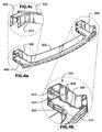
FIG. 4a is a rear perspective view of the crash management system ofFIG. 3 ; -
FIG. 4b is an enlarged detail view of a portion ofFIG. 4a lying within one of the dashed-line circles; -
FIG. 4c is an enlarged detail view of a portion ofFIG. 4a lying within the other one of the dashed-line circles; -
FIG. 5 is a simplified flow diagram of a method according to an embodiment of the instant invention; and, -
FIG. 6 is a simplified flow diagram of a method according to an embodiment of the instant invention. - The following description is presented to enable a person skilled in the art to make and use the invention, and is provided in the context of a particular application and its requirements. Various modifications to the disclosed embodiments will be readily apparent to those skilled in the art, and the general principles defined herein may be applied to other embodiments and applications without departing from the scope of the invention. Thus, the present invention is not intended to be limited to the embodiments disclosed, but is to be accorded the widest scope consistent with the principles and features disclosed herein.
- Referring to
FIG. 1 , shown is a rear perspective view of a crash management system according to a first embodiment of the instant invention. The crash management system comprises afirst shell 100a and asecond shell 100b. Thefirst shell 100a is formed from a first sheet metal blank and thesecond shell 100b is formed separately from a second sheet metal blank. By way of a specific and non-limiting example, the first and second sheet metal blanks each comprise 22MnB5 boron steel. More particularly, thefirst shell 100a and thesecond shell 100b are formed using a tailored tempering hot forming process, as is described in greater detail in the following sections. - The
first shell 100a comprises a high tensilestrength beam portion 102a. Integrally formed with thebeam portion 102a is a first low yield strengthcrash box portion 104a proximate a first end of the beam portion and a second low yield strengthcrash box portion 106a proximate a second end of the beam portion, the second end being opposite the first end. Similarly, thesecond shell 100b comprises a high tensilestrength beam portion 102b. Integrally formed with thebeam portion 102b is a first low yield strengthcrash box portion 104b proximate a first end of the beam portion and a second low yield strengthcrash box portion 106b proximate a second end of the beam portion, the second end being opposite the first end. - A typical value of the tensile strength of the
beam portions crash box portions 104a/b and 106a/b, respectively, is between about 200 N/mm2 and about 450 N/mm2. The yield strength of the crash box portions is adjustable during the hot forming process, to achieve desired values depending upon performance requirements. Due to the nature of the hot forming process that is used to form thefirst shell 100a and thesecond shell 100b, a transition zone exists between the high tensile strength material of thebeam portion 102a/b and the low yield strength material of the first and secondcrash box portions 104a/b and 106a/b. - Referring also to
FIG. 2 , shown is an enlarged cross-sectional view taken in the Plane A ofFIG. 1 . Thefirst shell 100a is a unitary component having a generally three-sided channel structure with one open side. Atop surface 200a of thefirst shell 100a extends into twoopposite sidewalls first rim 108a. Similarly, thesecond shell 100b is also a unitary component having a generally three-sided channel structure with one open side. Abottom surface 200b of thesecond shell 100b extends into twoopposite sidewalls opposite sidewalls second rim 108b. Thesecond rim 108b is shaped to nest inside thefirst rim 108a when thefirst shell 100a is fixedly secured to thesecond shell 100b. The generally three-sided channel structures extend the length of thebeam portions crash box portions 104a/b and 106a/b, respectively. Of course, it is to be understood that the terms "top" and "bottom" as used herein are defined in the context ofFIG. 2 , and that they are not intended to imply any required orientation of the crash management system when in an installed condition. - Optionally, the first and second
crash box portions 104a/b and 106a/b are formed with "beads" (not shown) to optimize folding behavior during an impact. - A method of making the crash management system of
FIG. 1 includes heating the first blank of flat sheet steel in a furnace to austenitic state, moving the first blank into a cooled pair of shaping tools, and then pressing the hot first blank into the shape of thefirst shell 100a. The shapedfirst shell 100a is maintained in the tools until thebeam portion 102a has hardened into an essentially martensitic structure with a tensile strength of between about 1300 N/mm2 and about 1600 N/mm2. During the time thefirst shell 100a is maintained in the tools, a portion of each tool adjacent the first and secondcrash box portions crash box portions crash box portions crash box portions - Similarly, the second blank of flat sheet steel is heated in a furnace to austenitic state, is moved into a cooled pair of shaping tools, and is pressed while still hot first into the shape of the
second shell 100b. The shapedsecond shell 100b is maintained in the tools until thebeam portion 102b has hardened into an essentially martensitic structure with a tensile strength of between about 1300 N/mm2 and about 1600 N/mm2. During the time thesecond shell 100b is maintained in the tools, a portion of each tool adjacent the first and secondcrash box portions crash box portions crash box portions crash box portions - The separately formed
first shell 100a andsecond shell 100b are aligned one with the other and then fixedly secured together. Some non-limiting techniques for fixedly securing thefirst shell 100a to thesecond shell 100b include: thermal joining (such as for instance spot welding, metal inert gas (MIG) welding, laser welding, etc.); adhesive bonding; and, mechanical coupling (such as for instance clinching or riveting). According to the first embodiment, thesecond shell 100b is a closing element that is fixedly secured to thefirst shell 100a. - Referring now to
FIG. 3 , shown is a front perspective view of a crash management system according to a second embodiment of the instant invention. The crash management system comprises a one-piece shell 300 that is formed from a first sheet metal blank, and a not illustrated closing element. By way of a specific and non-limiting example, the first sheet metal blanks comprises 22MnB5 boron steel. More particularly, the one-piece shell 300 is formed using a tailored tempering hot forming process, as is described in greater detail in the following sections. - The one-
piece shell 300 comprises a high tensilestrength beam portion 302. Integrally formed with thebeam portion 302 is a first low yield strengthcrash box portion 304 proximate a first end of the beam portion and a second low yield strengthcrash box portion 306 proximate a second end of the beam portion, the second end being opposite the first end. A typical value of the tensile strength of thebeam portion 302 is between about 1300 N/mm2 and about 1600 N/mm2. A typical value of the yield strength of the first and secondcrash box portions piece shell 300, a transition zone exists between the high tensile strength material of thebeam portion 300 and the low yield strength material of the first and secondcrash box portions - Referring now to
FIG. 4a , shown is a rear perspective view of the crash management system ofFIG. 3 . Also shown inFIG. 4a is theclosing element 400. - Referring also to
FIG. 4b , shown is an enlarged detail view of the portion ofFIG. 4a lying within the dashed-line circle. The one-piece shell 300 is a unitary component having a generally three-sided channel structure with one open side. Atop surface 402 of the one-piece shell 300 extends into twoopposite sidewalls rim 408. The generally three-sided channel structure extends the length of thebeam portion 302, and through the first and secondcrash box portions FIG. 4b , theclosing element 400 has aperipheral flange 410 for use in fixedly securing theclosing element 400 to therim 408 of the one-piece shell 300. Of course, it is to be understood that the term "top" as used herein is defined in the context ofFIG. 4 , and that it is not intended to imply any required orientation of the crash management system when in an installed condition. - Referring also to
FIG. 4c , shown is an enlarged detail view of a portion ofFIG. 4a lying within the other dashed-line circle.FIG. 4c shows that the corner between the crash boxes and the beam portion may optionally be notched out (notch 412), for formability reasons. - Optionally, the first and second
crash box portions - A method of making the crash management system of
FIG. 3 includes heating the first blank of flat sheet steel in a furnace to austenitic state, moving the first blank into a cooled pair of shaping tools, and then pressing the hot first blank into the shape of the one-piece shell 300. The shaped one-piece shell 300 is maintained in the tools until thebeam portion 302 has hardened into an essentially martensitic structure with a tensile strength of between about 1300 N/mm2 and about 1600 N/mm2. During the time the one-piece shell 300 is maintained in the tools, a portion of each tool adjacent the first and secondcrash box portions crash box portions crash box portions crash box portions - The
closing element 400 is separately shaped. Theflange 410 of theclosing element 400 is then aligned with therim 408 along the open side of the one-piece shell 300, and theclosing element 400 is fixedly secured to the one-piece shell 300. Some non-limiting techniques for fixedly securing the one-piece shell 300 to the closing element include: thermal joining (such as for instance spot welding, metal inert gas (MIG) welding, laser welding, etc.); adhesive bonding; and, mechanical coupling (such as for instance clinching or riveting). - Referring to
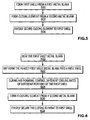
FIG. 5 , shown is a simplified flow diagram of a method according to an embodiment of the instant invention. At 500 a first shell is formed from a first sheet metal blank by a hot forming process, the first shell having a high tensile strength beam portion and integrally formed therewith a first low yield strength crash box portion proximate a first end of the beam portion and a second low yield strength crash box portion proximate a second end of the beam portion, the first shell having an open face extending continuously along the beam portion and each of the first and second crash box portions. At 502 a closing element is formed from a second sheet metal blank. At 504 the closing element is fixedly secured adjacent to the open face of the first shell. - Referring to
FIG. 6 , shown is a simplified flow diagram of a method according to an embodiment of the instant invention. At 600 a first sheet metal blank is heated to at least an austenitizing temperature of the metal. At 602 the austenitic blank is hot formed in a pair of cooled tools to form a first one-piece beam-box component having a generally three-sided channel structure with one open side. At 604, during the hot forming process, a beam portion of the formed component is cooled at a first rate that is sufficiently rapid to harden the beam portion into an essentially martensitic structure with a tensile strength of between about 1300 N/mm2 and about 1600 N/mm2, and crash box portions of the formed component are cooled at a second rate that is slower than the first rate, such that the crash box portions achieve a yield strength of between approximately 200 N/mm2 and 450 N/mm2. At 606 a closing element is formed from a second sheet metal blank. At 608 the closing element is fixedly secured along the open side of the first one-piece beam-box component. - The descriptions of the crash management systems according to the various embodiments of the instant invention have omitted any mention of routine mounting structures, such as through-holes etc., which are used for securing said crash management system to the longitudinal members of a vehicle chassis, or for securing a cushioning element or bumper cover to said crash management system. Nevertheless, a person having ordinary skill in the art will understand the requirements for such mounting structures, based on the various views that are presented in the appended drawings.
- In addition, the method of imparting tailored strength properties to the final components has been described only in terms of one specific and non-limiting method, in which a blank is heated uniformly to austenitic state and selected portions are cooled at a rate during forming, which results in lower strength in said selected portions relative to other portions. Optionally, only some portions of the blank are heated initially to austenitic state, and selected portions are either shielded from heating or kept in a lower temperature environment (e.g., external to a furnace or within a cooler furnace portion) such that the austenitizirig temperature of the material in said selected portions is not exceeded. Further optionally, the blank is formed and selected portions are heated subsequently (e.g., by inductive heating) to austenitic state and then rapidly cooled to achieve high strength in said selected portions. Still further optionally, the entire component is formed with rapid cooling, and subsequently selected portions are heated to a temperature that is sufficiently high to induce a phase change in said selected portions, followed by controlled cooling at a rate that results in a softening of the material in said selected portions relative to the non-heated portions.
- Depending on performance requirements, yield strengths of the first and second crash box portions may be outside of the range of approximately 200 N/mm2 and 450 N/mm2. This range currently is understood to provide acceptable performance, but should not be regarded as a strict requirement for achieving acceptable performance of the beam-box crash management component.
Claims (11)
- A method of making a beam-box crash management system, comprising:forming a first shell (100a, 300) from a first sheet metal blank by a hot forming process, the first shell (100a, 300) having a high tensile strength beam portion (102a, 302) and integrally formed therewith a first low yield strength crash box portion (104a, 304) proximate a first end of the beam portion (102a, 302) and a second low yield strength crash box portion (106a, 306) proximate a second end of the beam portion (102a, 302), the first shell (100a, 300) having an open face extending continuously along the beam portion (102a, 302) and each of the first and second crash box portions (104a, 304, 106a, 306),characterized byforming the closing element (100b, 400) comprises forming a second shell (100b) by a hot forming process, the second shell having a high tensile strength beam portion (102b) and integrally formed therewith a first low yield strength crash box portion (104b) proximate a first end of the beam portion (102b) and a second low yield strength crash box portion (106b) proximate a second end of the beam portion (102b), the second shell having an open face extending continuously along the beam portion (102b) and each of the first and second crash box portions (104b, 106b).
- A method according to claim 1, wherein the tensile strength of the beam portion (102a, 302) is between approximately 1300 N/mm2 and approximately 1600 N/mm2, wherein the yield strength of the first and second crash box portions (104a, 304, 106a, 306) is preferably between approximately 200 N/mm2 and 450 N/mm2.
- A method according to any one of claims 1 to 2, further comprising fixedly securing the closing element (100b, 400) adjacent to the open face of the first shell (100a, 300) comprises one of thermally joining, adhesively bonding and mechanically coupling the closing element (100b, 400) to the first shell (100a, 300).
- A method of one of the preceding claims, further comprising:heating the first sheet metal blank to at least an austenitizing temperature of the metal;hot forming the austenitic blank in a pair of cooled tools to form a first one piece beam-box component having a generally three-sided channel structure with one open side;during the hot forming process, cooling the beam portion (102a, 302) of the formed component at a first rate that is sufficiently rapid to harden the beam portion into an essentially martensitic structure with a tensile strength of between about 1300 N/mm2 and about 1600 N/mm2, and cooling crash box portions (104a, 304, 106a, 306) of the formed component at a second rate that is slower than the first rate, such that the crash box portions achieve a yield strength of between approximately 200 N/mm2 and 450 N/mm2.
- A method according claim 4, wherein forming the closing element further comprises:heating the second sheet metal blank to at least an austenitizing temperature of the metal;hot forming the austenitic blank in a pair of cooled tools to form a second one piece beam-box component having a generally three-sided channel structure with one open side;during the hot forming process, cooling a beam portion (102b) of the formed component at a first rate that is sufficiently rapid to harden the beam portion (102b) into an essentially martensitic structure with a tensile strength of between about 1300 N/mm2 and about 1600 N/mm2, and cooling crash box portions (104b, 106b) of the formed component at a second rate that is slower than the first rate, such that the crash box portions achieve a yield strength of between approximately 200 N/mm2 and 450 N/mm2.
- A beam-box crash management system, comprising:a first one piece shell (100a, 300) having a high tensile strength beam portion (102a, 302) and integrally formed therewith a first low yield strength crash box portion (104a, 304) proximate a first end of the beam portion (102a, 302) and a second low yield strength crash box portion (106a, 306) proximate a second end of the beam portion (102a, 302), the first one piece shell (100a, 300) having an open face extending continuously along the beam portion (102a, 302) and each of the first and second crash box portions (104a, 304, 106a, 306),characterized bya closing element (100b), which is a second one piece shell having a high tensile strength beam portion (102b) and integrally formed therewith a first low yield strength crash box portion (104b) proximate a first end of the beam portion (102b) and a second low yield strength crash box portion (106b) proximate a second end of the beam portion (102b), the second one piece shell having an open face extending continuously along the beam portion (102b) and each of the first and second crash box portions (104b, 106b).
- A beam-box crash management system according to claim 6, wherein the tensile strength of the beam portion (102a, 302) is between approximately 1300 N/mm2 and about 1600 N/mm2, wherein the yield strength of the first and second crash box portions (104a, 304, 106a, 306) is preferably between approximately
200 N/mm2 and 450 N/mm2. - A beam-box crash management system according to any one of claims 6 or 7, wherein the closing element (100b, 400) is fixedly secured adjacent to the open face of the first one piece shell by one of thermal joining, adhesive bonding and mechanical coupling of the closing element to the first one piece shell.
- A beam-box crash management system according to claim 6, wherein:the first one piece shell is a first beam-box shell (100a) fabricated from a first sheet metal blank, and the first beam-box shell (100a) has one open side defining a first rim (108a);the second one piece shell is a second beam-box shell (100b), fabricated from a second sheet metal blank, and the second beam-box shell (100b) has one open side defining a second rim (108b);wherein the first beam-box shell (100a) is fixedly secured to the second beam-box shell (100b) such that the first rim (108a) abuts the second rim (108b), and such that the beam portion (102a) of the first beam-box shell (100a) is aligned with the beam portion (102b) of the second beam-box shell (100b), and the first and second crash box structures (104a, 106a) of the first beam-box shell (100a) are aligned with a respective one of the first and second crash box structures (104b, 106b) of the second beam-box shell (100b).
- A beam-box crash management system according to claim 9, wherein the second rim (108b) is received within the first rim (108a) in a nesting arrangement when the first beam-box shell (100a) is fixedly secured to the second beam-box shell (100b).
- A beam-box crash management system according to claim 9 or 10, wherein the tensile strength of the beam portion (102a, 102b) is between approximately 1300 N/mm2 and approximately
1600 N/mm2, and wherein the yield strength of each of the first and second crash box portions (104a, 104b, 106a, 106b) is between approximately 200 N/mm2 and 450 N/mm2.
Applications Claiming Priority (2)
| Application Number | Priority Date | Filing Date | Title |
|---|---|---|---|
| US37014210P | 2010-08-03 | 2010-08-03 | |
| PCT/EP2011/003893 WO2012016692A1 (en) | 2010-08-03 | 2011-08-03 | Bumper assembly |
Publications (2)
| Publication Number | Publication Date |
|---|---|
| EP2601080A1 EP2601080A1 (en) | 2013-06-12 |
| EP2601080B1 true EP2601080B1 (en) | 2016-09-21 |
Family
ID=44789395
Family Applications (1)
| Application Number | Title | Priority Date | Filing Date |
|---|---|---|---|
| EP11767906.8A Not-in-force EP2601080B1 (en) | 2010-08-03 | 2011-08-03 | Bumper assembly |
Country Status (10)
| Country | Link |
|---|---|
| US (2) | US8770639B2 (en) |
| EP (1) | EP2601080B1 (en) |
| JP (1) | JP6092772B2 (en) |
| KR (1) | KR20130139847A (en) |
| CN (1) | CN103068635B (en) |
| BR (1) | BR112013002488A2 (en) |
| CA (1) | CA2804819A1 (en) |
| MX (1) | MX337841B (en) |
| RU (1) | RU2573117C2 (en) |
| WO (1) | WO2012016692A1 (en) |
Families Citing this family (17)
| Publication number | Priority date | Publication date | Assignee | Title |
|---|---|---|---|---|
| WO2012016692A1 (en) * | 2010-08-03 | 2012-02-09 | Cosma Engineering Europe Ag | Bumper assembly |
| DE102010052510A1 (en) * | 2010-11-26 | 2012-05-31 | Daimler Ag | Front end module arrangement for a body of a passenger car |
| CN104149722A (en) * | 2013-05-14 | 2014-11-19 | 北汽福田汽车股份有限公司 | Energy absorption and anticollision device on front portion of vehicle and vehicle body containing energy absorption and anticollision device |
| JP6187393B2 (en) | 2014-06-13 | 2017-08-30 | トヨタ自動車株式会社 | Bumper for vehicle |
| WO2016046582A1 (en) | 2014-09-22 | 2016-03-31 | Arcelormittal | Bumper-reinforcing system for motor vehicle |
| DE102014226542A1 (en) | 2014-12-19 | 2016-06-23 | Bayerische Motoren Werke Aktiengesellschaft | Press-hardened sheet-metal component with at least one predetermined breaking point, as well as component composite and motor vehicle body with such sheet metal component |
| JP2017035921A (en) * | 2015-08-07 | 2017-02-16 | 豊田鉄工株式会社 | Bumper reinforcement |
| DE102015117700A1 (en) * | 2015-10-16 | 2017-04-20 | Magna International Inc. | Cross member and method for producing a cross member |
| DE102016000515A1 (en) * | 2016-01-19 | 2017-07-20 | GM Global Technology Operations LLC (n. d. Ges. d. Staates Delaware) | bumper module |
| DE102016007371A1 (en) * | 2016-06-16 | 2017-12-21 | GM Global Technology Operations LLC (n. d. Ges. d. Staates Delaware) | Shock absorber for a vehicle |
| CN106494340A (en) * | 2016-10-25 | 2017-03-15 | 延锋彼欧汽车外饰系统有限公司 | A kind of bumper holder |
| US10633037B2 (en) | 2017-06-16 | 2020-04-28 | Ford Global Technologies, Llc | Vehicle underbody assembly with thermally treated rear rail |
| US11141769B2 (en) | 2017-06-16 | 2021-10-12 | Ford Global Technologies, Llc | Method and apparatus for forming varied strength zones of a vehicle component |
| US10556624B2 (en) | 2017-06-16 | 2020-02-11 | Ford Global Technologies, Llc | Vehicle underbody component protection assembly |
| US10399519B2 (en) | 2017-06-16 | 2019-09-03 | Ford Global Technologies, Llc | Vehicle bumper beam with varied strength zones |
| US10507776B2 (en) * | 2017-10-12 | 2019-12-17 | GM Global Technology Operations LLC | Fiber-reinforced composite bumper beam and crush members |
| DE102024101410A1 (en) * | 2024-01-18 | 2025-07-24 | ACPS Automotive GmbH | cross member |
Family Cites Families (26)
| Publication number | Priority date | Publication date | Assignee | Title |
|---|---|---|---|---|
| US3972744A (en) * | 1974-02-11 | 1976-08-03 | Houdaille Industries, Inc. | Method of and means for making lightweight, low cost impact resistant bumpers |
| DE2429496A1 (en) * | 1974-06-20 | 1976-01-08 | Volkswagenwerk Ag | CARRIERS, IN PARTICULAR LONGITUDINAL CARRIERS FOR VEHICLES |
| JPS61134457U (en) * | 1985-02-13 | 1986-08-21 | ||
| SE503450C2 (en) * | 1994-01-26 | 1996-06-17 | Plannja Hardtech Ab | Bumper beam |
| DE19511868A1 (en) * | 1995-03-31 | 1996-10-02 | Daimler Benz Ag | bumper |
| US5972134A (en) * | 1997-10-02 | 1999-10-26 | Benteler Ag | Manufacture of a metallic molded structural part |
| US6598923B2 (en) * | 2000-11-22 | 2003-07-29 | Alcoa Inc. | Joint structure and method for making a joint structure |
| US8123263B2 (en) * | 2001-09-27 | 2012-02-28 | Shape Corp. | Energy management beam |
| EP1457576B9 (en) * | 2001-11-27 | 2007-12-26 | Kikuchi Co., Ltd. | Press molding and its high frequency quenching method and its high frequency quenching system |
| RU2212469C1 (en) * | 2002-02-01 | 2003-09-20 | Акционерное общество закрытого типа "Радонеж" | Low-alloy steel and article made from this steel |
| DE10305725B3 (en) * | 2003-02-12 | 2004-04-08 | Benteler Automobiltechnik Gmbh | Production of a coated molded component made from hardened steel used in vehicles comprises cutting a mold plate from a coated coil material, cold forming the plate, and hot forming and/or partially hardening in the coating-free regions |
| US6971691B1 (en) * | 2004-06-25 | 2005-12-06 | Shape Corporation | Vehicle bumper beam |
| US6986536B1 (en) * | 2004-06-25 | 2006-01-17 | Shape Corporation | Vehicle bumper beam |
| NO20043579D0 (en) * | 2004-08-27 | 2004-08-27 | Norsk Hydro As | Shine, as well as method of making shine |
| US7703820B2 (en) * | 2005-04-29 | 2010-04-27 | Autotech Engineering, A.I.E. | Bumper reinforcing cross-member |
| DE102005021661B4 (en) * | 2005-05-06 | 2007-10-04 | Benteler Automobiltechnik Gmbh | crash box |
| JP5137322B2 (en) * | 2006-04-26 | 2013-02-06 | 新日鐵住金株式会社 | Bumper reinforcement |
| DE102006025854A1 (en) * | 2006-06-02 | 2007-12-06 | GM Global Technology Operations, Inc., Detroit | Motor vehicle body for a motor vehicle |
| US7461874B2 (en) * | 2006-08-30 | 2008-12-09 | Shape Corporation | Selectively annealed bumper beam |
| DE102007018459B4 (en) * | 2007-04-19 | 2011-11-24 | Audi Ag | Body component for a motor vehicle |
| DE102007024797A1 (en) * | 2007-05-26 | 2008-11-27 | Linde + Wiemann Gmbh Kg | Method for producing a profile component, profile component and use of a profile component |
| DE102007063629B4 (en) * | 2007-08-14 | 2016-07-07 | Benteler Automobiltechnik Gmbh | Method for producing a bumper arrangement of a motor vehicle |
| DE102009013322A1 (en) * | 2009-03-18 | 2010-09-30 | Benteler Automobiltechnik Gmbh | bumper assembly |
| US8967687B2 (en) * | 2010-04-09 | 2015-03-03 | Toyota Jidosha Kabushiki Kaisha | Bumper reinforcement structure |
| WO2012016692A1 (en) * | 2010-08-03 | 2012-02-09 | Cosma Engineering Europe Ag | Bumper assembly |
| JP6014430B2 (en) * | 2012-09-12 | 2016-10-25 | 株式会社アステア | bumper |
-
2011
- 2011-08-03 WO PCT/EP2011/003893 patent/WO2012016692A1/en not_active Ceased
- 2011-08-03 KR KR1020137002753A patent/KR20130139847A/en not_active Withdrawn
- 2011-08-03 CN CN201180037561.3A patent/CN103068635B/en not_active Expired - Fee Related
- 2011-08-03 RU RU2013102916/11A patent/RU2573117C2/en not_active IP Right Cessation
- 2011-08-03 BR BR112013002488A patent/BR112013002488A2/en not_active IP Right Cessation
- 2011-08-03 MX MX2013001318A patent/MX337841B/en active IP Right Grant
- 2011-08-03 JP JP2013522133A patent/JP6092772B2/en not_active Expired - Fee Related
- 2011-08-03 CA CA2804819A patent/CA2804819A1/en not_active Abandoned
- 2011-08-03 EP EP11767906.8A patent/EP2601080B1/en not_active Not-in-force
- 2011-08-03 US US13/810,784 patent/US8770639B2/en not_active Expired - Fee Related
-
2014
- 2014-06-15 US US14/304,952 patent/US9283908B2/en not_active Expired - Fee Related
Also Published As
| Publication number | Publication date |
|---|---|
| EP2601080A1 (en) | 2013-06-12 |
| JP2013535369A (en) | 2013-09-12 |
| RU2013102916A (en) | 2014-09-10 |
| US20130119683A1 (en) | 2013-05-16 |
| CN103068635A (en) | 2013-04-24 |
| US20140292008A1 (en) | 2014-10-02 |
| BR112013002488A2 (en) | 2016-05-31 |
| US9283908B2 (en) | 2016-03-15 |
| MX2013001318A (en) | 2013-03-18 |
| CN103068635B (en) | 2015-11-25 |
| CA2804819A1 (en) | 2012-02-09 |
| US8770639B2 (en) | 2014-07-08 |
| JP6092772B2 (en) | 2017-03-08 |
| RU2573117C2 (en) | 2016-01-20 |
| MX337841B (en) | 2016-03-22 |
| KR20130139847A (en) | 2013-12-23 |
| WO2012016692A1 (en) | 2012-02-09 |
Similar Documents
| Publication | Publication Date | Title |
|---|---|---|
| EP2601080B1 (en) | Bumper assembly | |
| US20240425119A1 (en) | Body side structural frame of a vehicle | |
| JP7206342B2 (en) | Vehicle rear structure and manufacturing method thereof | |
| CN103328312B (en) | The front side chassis structure of automobile | |
| US20140070552A1 (en) | Bumper | |
| US10479429B2 (en) | Process for manufacturing bumper reinforcement | |
| EP3006131B1 (en) | Method for manufacturing a rear frame side member for a motor vehicle, rear frame side member manufactured according to such a method, and motor vehicle provided with such a rear frame side member | |
| US20130127189A1 (en) | Bumper system for a vehicle | |
| KR100929528B1 (en) | Front side member assembly | |
| US20260001118A1 (en) | A unitary bumper beam assembly for a vehicle | |
| KR20130001427A (en) | Front side member for automobile |
Legal Events
| Date | Code | Title | Description |
|---|---|---|---|
| PUAI | Public reference made under article 153(3) epc to a published international application that has entered the european phase |
Free format text: ORIGINAL CODE: 0009012 |
|
| 17P | Request for examination filed |
Effective date: 20130131 |
|
| AK | Designated contracting states |
Kind code of ref document: A1 Designated state(s): AL AT BE BG CH CY CZ DE DK EE ES FI FR GB GR HR HU IE IS IT LI LT LU LV MC MK MT NL NO PL PT RO RS SE SI SK SM TR |
|
| DAX | Request for extension of the european patent (deleted) | ||
| 17Q | First examination report despatched |
Effective date: 20140312 |
|
| GRAP | Despatch of communication of intention to grant a patent |
Free format text: ORIGINAL CODE: EPIDOSNIGR1 |
|
| INTG | Intention to grant announced |
Effective date: 20160226 |
|
| GRAS | Grant fee paid |
Free format text: ORIGINAL CODE: EPIDOSNIGR3 |
|
| GRAA | (expected) grant |
Free format text: ORIGINAL CODE: 0009210 |
|
| AK | Designated contracting states |
Kind code of ref document: B1 Designated state(s): AL AT BE BG CH CY CZ DE DK EE ES FI FR GB GR HR HU IE IS IT LI LT LU LV MC MK MT NL NO PL PT RO RS SE SI SK SM TR |
|
| REG | Reference to a national code |
Ref country code: GB Ref legal event code: FG4D |
|
| REG | Reference to a national code |
Ref country code: CH Ref legal event code: EP |
|
| REG | Reference to a national code |
Ref country code: AT Ref legal event code: REF Ref document number: 830752 Country of ref document: AT Kind code of ref document: T Effective date: 20161015 |
|
| REG | Reference to a national code |
Ref country code: IE Ref legal event code: FG4D |
|
| REG | Reference to a national code |
Ref country code: DE Ref legal event code: R096 Ref document number: 602011030586 Country of ref document: DE |
|
| REG | Reference to a national code |
Ref country code: LT Ref legal event code: MG4D Ref country code: NL Ref legal event code: MP Effective date: 20160921 |
|
| PG25 | Lapsed in a contracting state [announced via postgrant information from national office to epo] |
Ref country code: FI Free format text: LAPSE BECAUSE OF FAILURE TO SUBMIT A TRANSLATION OF THE DESCRIPTION OR TO PAY THE FEE WITHIN THE PRESCRIBED TIME-LIMIT Effective date: 20160921 Ref country code: LT Free format text: LAPSE BECAUSE OF FAILURE TO SUBMIT A TRANSLATION OF THE DESCRIPTION OR TO PAY THE FEE WITHIN THE PRESCRIBED TIME-LIMIT Effective date: 20160921 Ref country code: NO Free format text: LAPSE BECAUSE OF FAILURE TO SUBMIT A TRANSLATION OF THE DESCRIPTION OR TO PAY THE FEE WITHIN THE PRESCRIBED TIME-LIMIT Effective date: 20161221 Ref country code: RS Free format text: LAPSE BECAUSE OF FAILURE TO SUBMIT A TRANSLATION OF THE DESCRIPTION OR TO PAY THE FEE WITHIN THE PRESCRIBED TIME-LIMIT Effective date: 20160921 |
|
| REG | Reference to a national code |
Ref country code: AT Ref legal event code: MK05 Ref document number: 830752 Country of ref document: AT Kind code of ref document: T Effective date: 20160921 |
|
| PG25 | Lapsed in a contracting state [announced via postgrant information from national office to epo] |
Ref country code: NL Free format text: LAPSE BECAUSE OF FAILURE TO SUBMIT A TRANSLATION OF THE DESCRIPTION OR TO PAY THE FEE WITHIN THE PRESCRIBED TIME-LIMIT Effective date: 20160921 Ref country code: SE Free format text: LAPSE BECAUSE OF FAILURE TO SUBMIT A TRANSLATION OF THE DESCRIPTION OR TO PAY THE FEE WITHIN THE PRESCRIBED TIME-LIMIT Effective date: 20160921 Ref country code: GR Free format text: LAPSE BECAUSE OF FAILURE TO SUBMIT A TRANSLATION OF THE DESCRIPTION OR TO PAY THE FEE WITHIN THE PRESCRIBED TIME-LIMIT Effective date: 20161222 Ref country code: LV Free format text: LAPSE BECAUSE OF FAILURE TO SUBMIT A TRANSLATION OF THE DESCRIPTION OR TO PAY THE FEE WITHIN THE PRESCRIBED TIME-LIMIT Effective date: 20160921 |
|
| PG25 | Lapsed in a contracting state [announced via postgrant information from national office to epo] |
Ref country code: EE Free format text: LAPSE BECAUSE OF FAILURE TO SUBMIT A TRANSLATION OF THE DESCRIPTION OR TO PAY THE FEE WITHIN THE PRESCRIBED TIME-LIMIT Effective date: 20160921 Ref country code: RO Free format text: LAPSE BECAUSE OF FAILURE TO SUBMIT A TRANSLATION OF THE DESCRIPTION OR TO PAY THE FEE WITHIN THE PRESCRIBED TIME-LIMIT Effective date: 20160921 |
|
| PG25 | Lapsed in a contracting state [announced via postgrant information from national office to epo] |
Ref country code: SK Free format text: LAPSE BECAUSE OF FAILURE TO SUBMIT A TRANSLATION OF THE DESCRIPTION OR TO PAY THE FEE WITHIN THE PRESCRIBED TIME-LIMIT Effective date: 20160921 Ref country code: PT Free format text: LAPSE BECAUSE OF FAILURE TO SUBMIT A TRANSLATION OF THE DESCRIPTION OR TO PAY THE FEE WITHIN THE PRESCRIBED TIME-LIMIT Effective date: 20170123 Ref country code: CZ Free format text: LAPSE BECAUSE OF FAILURE TO SUBMIT A TRANSLATION OF THE DESCRIPTION OR TO PAY THE FEE WITHIN THE PRESCRIBED TIME-LIMIT Effective date: 20160921 Ref country code: PL Free format text: LAPSE BECAUSE OF FAILURE TO SUBMIT A TRANSLATION OF THE DESCRIPTION OR TO PAY THE FEE WITHIN THE PRESCRIBED TIME-LIMIT Effective date: 20160921 Ref country code: ES Free format text: LAPSE BECAUSE OF FAILURE TO SUBMIT A TRANSLATION OF THE DESCRIPTION OR TO PAY THE FEE WITHIN THE PRESCRIBED TIME-LIMIT Effective date: 20160921 Ref country code: BG Free format text: LAPSE BECAUSE OF FAILURE TO SUBMIT A TRANSLATION OF THE DESCRIPTION OR TO PAY THE FEE WITHIN THE PRESCRIBED TIME-LIMIT Effective date: 20161221 Ref country code: BE Free format text: LAPSE BECAUSE OF FAILURE TO SUBMIT A TRANSLATION OF THE DESCRIPTION OR TO PAY THE FEE WITHIN THE PRESCRIBED TIME-LIMIT Effective date: 20160921 Ref country code: AT Free format text: LAPSE BECAUSE OF FAILURE TO SUBMIT A TRANSLATION OF THE DESCRIPTION OR TO PAY THE FEE WITHIN THE PRESCRIBED TIME-LIMIT Effective date: 20160921 Ref country code: IS Free format text: LAPSE BECAUSE OF FAILURE TO SUBMIT A TRANSLATION OF THE DESCRIPTION OR TO PAY THE FEE WITHIN THE PRESCRIBED TIME-LIMIT Effective date: 20170121 Ref country code: SM Free format text: LAPSE BECAUSE OF FAILURE TO SUBMIT A TRANSLATION OF THE DESCRIPTION OR TO PAY THE FEE WITHIN THE PRESCRIBED TIME-LIMIT Effective date: 20160921 |
|
| REG | Reference to a national code |
Ref country code: DE Ref legal event code: R097 Ref document number: 602011030586 Country of ref document: DE |
|
| PG25 | Lapsed in a contracting state [announced via postgrant information from national office to epo] |
Ref country code: IT Free format text: LAPSE BECAUSE OF FAILURE TO SUBMIT A TRANSLATION OF THE DESCRIPTION OR TO PAY THE FEE WITHIN THE PRESCRIBED TIME-LIMIT Effective date: 20160921 |
|
| PLBE | No opposition filed within time limit |
Free format text: ORIGINAL CODE: 0009261 |
|
| STAA | Information on the status of an ep patent application or granted ep patent |
Free format text: STATUS: NO OPPOSITION FILED WITHIN TIME LIMIT |
|
| PG25 | Lapsed in a contracting state [announced via postgrant information from national office to epo] |
Ref country code: DK Free format text: LAPSE BECAUSE OF FAILURE TO SUBMIT A TRANSLATION OF THE DESCRIPTION OR TO PAY THE FEE WITHIN THE PRESCRIBED TIME-LIMIT Effective date: 20160921 |
|
| 26N | No opposition filed |
Effective date: 20170622 |
|
| PGFP | Annual fee paid to national office [announced via postgrant information from national office to epo] |
Ref country code: DE Payment date: 20170725 Year of fee payment: 7 |
|
| PG25 | Lapsed in a contracting state [announced via postgrant information from national office to epo] |
Ref country code: SI Free format text: LAPSE BECAUSE OF FAILURE TO SUBMIT A TRANSLATION OF THE DESCRIPTION OR TO PAY THE FEE WITHIN THE PRESCRIBED TIME-LIMIT Effective date: 20160921 |
|
| REG | Reference to a national code |
Ref country code: CH Ref legal event code: PL |
|
| PG25 | Lapsed in a contracting state [announced via postgrant information from national office to epo] |
Ref country code: MC Free format text: LAPSE BECAUSE OF FAILURE TO SUBMIT A TRANSLATION OF THE DESCRIPTION OR TO PAY THE FEE WITHIN THE PRESCRIBED TIME-LIMIT Effective date: 20160921 |
|
| GBPC | Gb: european patent ceased through non-payment of renewal fee |
Effective date: 20170803 |
|
| PG25 | Lapsed in a contracting state [announced via postgrant information from national office to epo] |
Ref country code: CH Free format text: LAPSE BECAUSE OF NON-PAYMENT OF DUE FEES Effective date: 20170831 Ref country code: LI Free format text: LAPSE BECAUSE OF NON-PAYMENT OF DUE FEES Effective date: 20170831 |
|
| REG | Reference to a national code |
Ref country code: FR Ref legal event code: ST Effective date: 20180430 |
|
| REG | Reference to a national code |
Ref country code: IE Ref legal event code: MM4A |
|
| PG25 | Lapsed in a contracting state [announced via postgrant information from national office to epo] |
Ref country code: LU Free format text: LAPSE BECAUSE OF NON-PAYMENT OF DUE FEES Effective date: 20170803 |
|
| PG25 | Lapsed in a contracting state [announced via postgrant information from national office to epo] |
Ref country code: IE Free format text: LAPSE BECAUSE OF NON-PAYMENT OF DUE FEES Effective date: 20170803 Ref country code: GB Free format text: LAPSE BECAUSE OF NON-PAYMENT OF DUE FEES Effective date: 20170803 |
|
| PG25 | Lapsed in a contracting state [announced via postgrant information from national office to epo] |
Ref country code: FR Free format text: LAPSE BECAUSE OF NON-PAYMENT OF DUE FEES Effective date: 20170831 |
|
| PG25 | Lapsed in a contracting state [announced via postgrant information from national office to epo] |
Ref country code: MT Free format text: LAPSE BECAUSE OF NON-PAYMENT OF DUE FEES Effective date: 20170803 |
|
| PG25 | Lapsed in a contracting state [announced via postgrant information from national office to epo] |
Ref country code: AL Free format text: LAPSE BECAUSE OF FAILURE TO SUBMIT A TRANSLATION OF THE DESCRIPTION OR TO PAY THE FEE WITHIN THE PRESCRIBED TIME-LIMIT Effective date: 20160921 |
|
| REG | Reference to a national code |
Ref country code: DE Ref legal event code: R119 Ref document number: 602011030586 Country of ref document: DE |
|
| PG25 | Lapsed in a contracting state [announced via postgrant information from national office to epo] |
Ref country code: HU Free format text: LAPSE BECAUSE OF FAILURE TO SUBMIT A TRANSLATION OF THE DESCRIPTION OR TO PAY THE FEE WITHIN THE PRESCRIBED TIME-LIMIT; INVALID AB INITIO Effective date: 20110803 |
|
| PG25 | Lapsed in a contracting state [announced via postgrant information from national office to epo] |
Ref country code: DE Free format text: LAPSE BECAUSE OF NON-PAYMENT OF DUE FEES Effective date: 20190301 |
|
| PG25 | Lapsed in a contracting state [announced via postgrant information from national office to epo] |
Ref country code: CY Free format text: LAPSE BECAUSE OF NON-PAYMENT OF DUE FEES Effective date: 20160921 |
|
| PG25 | Lapsed in a contracting state [announced via postgrant information from national office to epo] |
Ref country code: MK Free format text: LAPSE BECAUSE OF FAILURE TO SUBMIT A TRANSLATION OF THE DESCRIPTION OR TO PAY THE FEE WITHIN THE PRESCRIBED TIME-LIMIT Effective date: 20160921 |
|
| PG25 | Lapsed in a contracting state [announced via postgrant information from national office to epo] |
Ref country code: TR Free format text: LAPSE BECAUSE OF FAILURE TO SUBMIT A TRANSLATION OF THE DESCRIPTION OR TO PAY THE FEE WITHIN THE PRESCRIBED TIME-LIMIT Effective date: 20160921 |
|
| PG25 | Lapsed in a contracting state [announced via postgrant information from national office to epo] |
Ref country code: HR Free format text: LAPSE BECAUSE OF FAILURE TO SUBMIT A TRANSLATION OF THE DESCRIPTION OR TO PAY THE FEE WITHIN THE PRESCRIBED TIME-LIMIT Effective date: 20160921 |