EP2600553A1 - Method and system for traffic management and resource allocation on a shared access network - Google Patents
Method and system for traffic management and resource allocation on a shared access network Download PDFInfo
- Publication number
- EP2600553A1 EP2600553A1 EP12194700.6A EP12194700A EP2600553A1 EP 2600553 A1 EP2600553 A1 EP 2600553A1 EP 12194700 A EP12194700 A EP 12194700A EP 2600553 A1 EP2600553 A1 EP 2600553A1
- Authority
- EP
- European Patent Office
- Prior art keywords
- traffic
- rate
- gateway
- priority
- queue
- Prior art date
- Legal status (The legal status is an assumption and is not a legal conclusion. Google has not performed a legal analysis and makes no representation as to the accuracy of the status listed.)
- Granted
Links
Images


Classifications
-
- H—ELECTRICITY
- H04—ELECTRIC COMMUNICATION TECHNIQUE
- H04W—WIRELESS COMMUNICATION NETWORKS
- H04W72/00—Local resource management
- H04W72/50—Allocation or scheduling criteria for wireless resources
- H04W72/56—Allocation or scheduling criteria for wireless resources based on priority criteria
-
- H—ELECTRICITY
- H04—ELECTRIC COMMUNICATION TECHNIQUE
- H04B—TRANSMISSION
- H04B7/00—Radio transmission systems, i.e. using radiation field
- H04B7/14—Relay systems
- H04B7/15—Active relay systems
- H04B7/185—Space-based or airborne stations; Stations for satellite systems
- H04B7/18578—Satellite systems for providing broadband data service to individual earth stations
- H04B7/18582—Arrangements for data linking, i.e. for data framing, for error recovery, for multiple access
-
- H—ELECTRICITY
- H04—ELECTRIC COMMUNICATION TECHNIQUE
- H04L—TRANSMISSION OF DIGITAL INFORMATION, e.g. TELEGRAPHIC COMMUNICATION
- H04L1/00—Arrangements for detecting or preventing errors in the information received
- H04L1/0001—Systems modifying transmission characteristics according to link quality, e.g. power backoff
- H04L1/0002—Systems modifying transmission characteristics according to link quality, e.g. power backoff by adapting the transmission rate
- H04L1/0003—Systems modifying transmission characteristics according to link quality, e.g. power backoff by adapting the transmission rate by switching between different modulation schemes
-
- H—ELECTRICITY
- H04—ELECTRIC COMMUNICATION TECHNIQUE
- H04L—TRANSMISSION OF DIGITAL INFORMATION, e.g. TELEGRAPHIC COMMUNICATION
- H04L1/00—Arrangements for detecting or preventing errors in the information received
- H04L1/0001—Systems modifying transmission characteristics according to link quality, e.g. power backoff
- H04L1/0009—Systems modifying transmission characteristics according to link quality, e.g. power backoff by adapting the channel coding
-
- H—ELECTRICITY
- H04—ELECTRIC COMMUNICATION TECHNIQUE
- H04L—TRANSMISSION OF DIGITAL INFORMATION, e.g. TELEGRAPHIC COMMUNICATION
- H04L41/00—Arrangements for maintenance, administration or management of data switching networks, e.g. of packet switching networks
- H04L41/50—Network service management, e.g. ensuring proper service fulfilment according to agreements
- H04L41/5003—Managing SLA; Interaction between SLA and QoS
- H04L41/5019—Ensuring fulfilment of SLA
- H04L41/5022—Ensuring fulfilment of SLA by giving priorities, e.g. assigning classes of service
-
- H—ELECTRICITY
- H04—ELECTRIC COMMUNICATION TECHNIQUE
- H04L—TRANSMISSION OF DIGITAL INFORMATION, e.g. TELEGRAPHIC COMMUNICATION
- H04L47/00—Traffic control in data switching networks
- H04L47/70—Admission control; Resource allocation
- H04L47/82—Miscellaneous aspects
- H04L47/821—Prioritising resource allocation or reservation requests
-
- H—ELECTRICITY
- H04—ELECTRIC COMMUNICATION TECHNIQUE
- H04W—WIRELESS COMMUNICATION NETWORKS
- H04W24/00—Supervisory, monitoring or testing arrangements
- H04W24/08—Testing, supervising or monitoring using real traffic
-
- H—ELECTRICITY
- H04—ELECTRIC COMMUNICATION TECHNIQUE
- H04L—TRANSMISSION OF DIGITAL INFORMATION, e.g. TELEGRAPHIC COMMUNICATION
- H04L1/00—Arrangements for detecting or preventing errors in the information received
- H04L1/004—Arrangements for detecting or preventing errors in the information received by using forward error control
- H04L1/0056—Systems characterized by the type of code used
- H04L1/0057—Block codes
-
- H—ELECTRICITY
- H04—ELECTRIC COMMUNICATION TECHNIQUE
- H04L—TRANSMISSION OF DIGITAL INFORMATION, e.g. TELEGRAPHIC COMMUNICATION
- H04L47/00—Traffic control in data switching networks
- H04L47/50—Queue scheduling
- H04L47/62—Queue scheduling characterised by scheduling criteria
- H04L47/625—Queue scheduling characterised by scheduling criteria for service slots or service orders
- H04L47/627—Queue scheduling characterised by scheduling criteria for service slots or service orders policing
-
- H—ELECTRICITY
- H04—ELECTRIC COMMUNICATION TECHNIQUE
- H04L—TRANSMISSION OF DIGITAL INFORMATION, e.g. TELEGRAPHIC COMMUNICATION
- H04L47/00—Traffic control in data switching networks
- H04L47/50—Queue scheduling
- H04L47/62—Queue scheduling characterised by scheduling criteria
- H04L47/625—Queue scheduling characterised by scheduling criteria for service slots or service orders
- H04L47/6275—Queue scheduling characterised by scheduling criteria for service slots or service orders based on priority
-
- Y—GENERAL TAGGING OF NEW TECHNOLOGICAL DEVELOPMENTS; GENERAL TAGGING OF CROSS-SECTIONAL TECHNOLOGIES SPANNING OVER SEVERAL SECTIONS OF THE IPC; TECHNICAL SUBJECTS COVERED BY FORMER USPC CROSS-REFERENCE ART COLLECTIONS [XRACs] AND DIGESTS
- Y02—TECHNOLOGIES OR APPLICATIONS FOR MITIGATION OR ADAPTATION AGAINST CLIMATE CHANGE
- Y02D—CLIMATE CHANGE MITIGATION TECHNOLOGIES IN INFORMATION AND COMMUNICATION TECHNOLOGIES [ICT], I.E. INFORMATION AND COMMUNICATION TECHNOLOGIES AIMING AT THE REDUCTION OF THEIR OWN ENERGY USE
- Y02D30/00—Reducing energy consumption in communication networks
- Y02D30/50—Reducing energy consumption in communication networks in wire-line communication networks, e.g. low power modes or reduced link rate
Definitions
- traffic may be admitted, shaped, or shed, and backpressure may be provided to ingress traffic as a function of either a static estimate of the available bandwidth based on the mean and standard deviation of typical conditions, a semi-static estimate of the available bandwidth based on historical analysis of the conditions, or a slow moving tracking of the long term changes of the conditions.
- QoS quality of service
- the traffic from numerous sources may be multiplexed into a data stream that may be transmitted over an air interface. Due to various QoS requirements and customer classification criteria, the incoming traffic data may first be grouped into multiple IP layer and acceleration gateways before multiplexing into a link layer gateway, where the data stream to be sent over the air interface is formed.
- IPGW IP gateway
- SGW satellite gateway
- the data stream may be broadcast to remote network nodes, such as Very Small Aperture Terminals (VSATs).
- VSATs Very Small Aperture Terminals
- Network resource management and traffic flow control may be used to efficiently utilize the available bandwidth and at the same time provide satisfactory QoS to different traffic classes.
- a method for traffic management and resource allocation on a shared access network includes estimating a bandwidth capacity of a gateway, determining a demand rate of an IP gateway, allocating bandwidth to the IP gateway based on the demand rate, traffic priority, or traffic weighting, allocating bandwidth to the IP gateway in advance of demand when excess bandwidth is available, scheduling traffic at the IP gateway based on traffic priority, service plan of a VSAT, or physical layer properties of the VSAT, performing priority queue servicing of traffic at a gateway using a real time traffic priority queue, a non-real time traffic priority queue, two or more modulation and coding queue groups, and a code block queue.
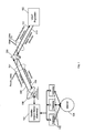
- FIG. 1 depicts an exemplary satellite communications system
- FIG. 2 depicts an exemplary traffic management architecture implemented in a gateway and IP gateways
- FIG. 3 depicts an exemplary procedure for capacity estimation
- FIG. 4 depicts an exemplary procedure for non-realtime demand determination
- FIG. 5 depicts an exemplary procedure for resource allocation
- FIG. 6 depicts an exemplary procedure for multi-class scheduling
- Fig. 7 depicts an exemplary queuing architecture.
- FIG. 1 depicts an exemplary satellite communications system.
- the satellite communications system may include a satellite ground station, or gateway, 101, a Very Small Aperture Terminal (VSAT) population 102, a satellite 103, the Internet 104, IP gateways 105, and a RF terminal 106.
- VSAT Very Small Aperture Terminal
- the satellite communications system may be one type of shared access network.
- Other types of shared access networks may include wireless networks such as 4G LTE and WiMAX networks, which may include terminals other than VSATs, such as cellular and WiFi equipped devices.
- the gateway 101 may be connected to the VSATs in the VSAT population 102 through the satellite 103.
- Feeder links 107 may carry data between the gateway 101 and the satellite 103, and may include a forward uplink 108 for transmitting data from the gateway 101 to the satellite 103, and the return downlink 109 for transmitting data from the satellite 103 to the gateway 101.
- User links 110 may carry data between the satellite 103 and the VSAT population 102, and may include the return uplink 111 for transmitting data from a VSAT to the satellite 103, and a forward downlink 112 for transmitting data from the satellite 103 to a VSAT.
- the forward uplink 108 and the forward downlink 112 may form an outroute, and the return uplink 111 and the return downlink 109 may form an inroute.
- the gateway 101 may be high capacity, large antenna earth stations with connectivity to ground telecommunications infrastructure.
- the gateway 101 may be connected to the RF Terminal (RFT) 106.
- the RFT 106 may include an antenna, electronics and connectivity to allow for communications access to the satellite 103.
- the RFT 106 may be the physical equipment responsible for the sending and receiving of signals to and from the satellite 103, and may provide an air interface for the gateway 101.
- the VSAT population 102 may include a number of VSATs or Mobile Satellite Terminals, which may be used by end users to access the satellite communications system.
- a VSAT may include a remote satellite dish for receiving RF signals from and transmitting RF signals to the satellite 103, a satellite modem and other equipment for managing the sending and receiving of data, and one or more remote hosts, which may be computer systems or other electronic devices capable of network communications at a site remote the gateway 101.
- a VSAT may be used at a residence or place of business to provide access to the Internet 104.
- the satellite 103 may be any suitable communications satellite for connecting the hub 101 to the remote hosts 116.
- the satellite 103 may be a simple bent-pipe design geostationary satellite, which can accommodate innovations and variations in transmission parameters, operating in the Ka-band.
- the satellite 103 may use spot beams and frequency and polarization reuse to maximize the total capacity of the system.
- Signals passing through the satellite 103 in the forward direction, towards the VSATs, may be based on the DVB S.2 standard (ETSI EN 302 307) using signal constellations up to and including at least 16-APSK.
- the signals intended to pass through the satellite 103 in the return direction, toward the hubs may be based on the IPoS standard (ETSI TS 102 354).
- Other suitable signal types may also be used in either direction, including, for example higher data rate variations of DVB S.2.
- the gateway 101 may include the IP gateways 105.
- the IP gateways 105 may be the ingress portion of the local network at the gateway 101. Data from outside the gateway 101 may enter the gateway 101 through the IP gateways 105.
- the IP gateways 105 may include a spoofer, which may acknowledge IP traffic, including TCP traffic, sent to the gateway 101.
- the gateway 101 may be connected to the Internet 104 through the IP gateways 105. IP traffic, including TCP traffic, from the Internet 104 may enter the gateway 101 through the IP gateways 105.
- Remote terminals connected to VSATs in the VSAT population 102 may connect to the Internet 104 through the satellite 103 and the gateway 101.
- IP gateways 105 may be connected to one gateway 101, sharing the bandwidth of the RFT 106.
- real-time (RT) and non-realtime (NRT) traffic flows may be classified into different priorities. These traffic flows may be processed and multiplexed before being forwarded to priority queues at the gateway 101. RT traffic may go directly to the gateway 101 RT priority queue, while NRT traffic flows may be serviced based on the respective priority and volume. The data may be further packed into DVB-S2 code blocks and stored in a code block buffer before transmission.
- Data from the Internet 104 intended for a VSAT in the VSAT population 102 may be in the form of IP packets, including TCP packets and UDP packets, or any other suitable IP packets, and may enter the gateway 101 at one of the IP gateways 105, where the spoofer may send acknowledgement back to the sender of the IP packets.
- the IP packets may be processed and multiplexed by the gateway 101 along with IP packets from the other IP gateways 105, where the IP gateways 105 may or may not have the same service capabilities and relative priorities.
- the IP packets may then be transmitted to the satellite 103 on the forward uplink 108 using the air interface provided by the RFT 106.
- the satellite 103 may then transmit the IP packets to the VSAT using the forward downlink 112.
- IP packets may enter the ingress at a VSAT in the VSAT population 102, be processed by the VSAT 102, and transmitted to the satellite 103 via the VSAT's air interface on the return uplink 111.
- the satellite 103 may then send the IP packets to the gateway 101 using the return downlink 109. This may be the inroute.
- FIG. 2 depicts an exemplary traffic management architecture implemented in a gateway and IP gateways.
- the IP gateways 105 may receive non-RT traffic 201 and RT traffic 202 destined for a VSAT in the VSAT population 102, from, for example, the Internet 104.
- the non-RT traffic 201 may be, for example, data packets belonging to interactive, multicast, streaming, and bulk traffic.
- the RT traffic 202 may be, for example, data packets belonging to Voice-over-IP traffic.
- the gateway 101 and the IP gateways 105 may use a number of algorithms to manage traffic flow and resource allocation. The various algorithms may interact with each other, both within and between the gateway 101 and the IP gateways 105, and may allow for improved spectrum utilization, fairness, latency, and throughput performance of the shared access network.
- These algorithms may be implemented as a capacity estimation module 205, an NRT demand determination module 206, a resource allocation module 207, a multi-class scheduling module 208, and a priority queue servicing module 209.
- the algorithms may be used to ensure that the gateway 101 priority queues are sent the NRT traffic 201 at a rate that does to not let the queues be empty but also not allow them to overflow or incur unnecessary latency.
- the capacity estimation module 205 may be any suitable combination of hardware and software in the gateway 101 for estimating the available data capacity of the gateway 101 based on the distribution of traffic and how the traffic can be transmitted on the physical layer interface, such as the RFT 106, for example, by using different modulation and coding per remote network node.
- FIG. 3 depicts an exemplary procedure for capacity estimation.
- the capacity estimation module 205 may use an algorithm to estimate the available bandwidth for the RT traffic 202 and NRT traffic 201 of a given DVB-S2 carrier stream, and may operate at a per code rate organizer (CRO) basis.
- the dynamic change in available bandwidth tracked by the capacity estimation module 205 may be a function of the mix of traffic, the capabilities of the VSATs receiving the traffic, current weather and interference conditions at the VSATs, and current weather and interference conditions at the gateway 101.
- the output from the capacity estimation module 205 may be used by the resource allocation module 207 as the bandwidth pool upon which dynamic rate allocations are granted.
- the capacity estimation module 205 may collect code block statistics when code blocks are delivered from modulation and coding (MODCOD) queues to a code block buffer 204. Code blocks may include data from incoming data packets that will be encoded and modulated.
- MODCOD modulation and coding
- the code blocks may be sampled.
- the capacity estimation module 205 may sample the code blocks passing through the gateway 101.
- ⁇ T may be the IP gateway-gateway flow control update period, and may have a default value of 100 ms.
- ⁇ t may be the sampling interval of code blocks from a MODCOD queue group. With two separate MODCOD groups, the code blocks for RT traffic 202 and NRT traffic 201, the groups may be sampled separately.
- the capacity estimation module may also handle more than two MODCOD groups. There may be N types of code blocks, and thus N different MODCOD queues per MODCOD group.
- a total symbol rate may be calculated.
- M i may be the number of effective bits per symbol of type i, which may be a function of a modulation and coding rate for MODCOD type i.
- the total number of bits in one code block may be b CB , which may be, for example, 64800 bits or 16200 bits.
- a ratio of total symbols may be calculated.
- R may be the number of symbols per time ⁇ T, which may be found given the DVB-S2 carrier stream symbol rate for the gateway 101.
- the total number of information bits may be calculated.
- the calculated total number of information bits may be filtered.
- X(t) may be the overall estimated information rate at time t, in bits per second.
- real time usage may be calculated.
- the number of the code blocks of type i, K i may include code blocks from both the RT traffic 202 and the NRT traffic 201.
- the exact information bit rate may be used.
- K i may be the number of code blocks
- B i may be information bits per code block of type i.
- X RT (t) may be the estimated information rate at time t.
- Y RT (t) X RT (t).
- the estimated capacity available for non real time traffic may be calculated.
- a real time portion may be calculated.
- the gateway 101 may have a threshold for the RT traffic 202 ⁇ * , which may be an RT threshold.
- the RT portion may be dynamically updated and transparent to all of the IP gateways 105.
- the NRT demand determination module 206 may be any suitable combination of hardware and software in the IP gateways 105 for estimating bandwidth demand for non real time traffic, such as the NRT traffic 201, in the next resource allocation period.
- the NRT demand determination module 206 may provide to the gateway 101, on a per CRO basis, the demand profile of the IP gateway 105, facilitating the decision making for resource allocation in the gateway 101.
- Demand determination may be based on the current usage of network resource plus a margin that may take into account the short term traffic fluctuation.
- each of the IP gateways 105 may send a request of demand to the gateway 101 on a per CRO basis, and may receive granted rates for scheduling multiple traffic classes.
- FIG. 4 depicts an exemplary procedure for NRT demand determination.
- the total arriving traffic volume for interactive traffic may be calculated.
- the NRT demand determination module 206 may use measurements of the mean and standard deviation of arriving interactive traffic combined with a lower, or minimum, and an upper, or maximum, limit.
- ⁇ T which may be, for example, 100 ms
- M 5
- x j i may be obtained by counting the instant amount of packets at j-th frame and multiplying that by the packet size in bytes or bits.
- a mean and standard deviation of total arriving traffic volume for interactive traffic may be calculated.
- a moving average for total arriving traffic volume for interactive traffic may be calculated.
- ⁇ may be a weighing factor, 0 ⁇ ⁇ ⁇ 1.
- the default value for ⁇ may be 0.35.
- an upper demand estimation may be calculated for interactive traffic.
- Interactive traffic may be subject to a strict delay requirement, so a margin may be provided to accommodate the traffic fluctuation.
- d ⁇ ( Y k ) std may be referred to as the demand margin for all the flows of interactive traffic class in the IP gateway 105 being serviced by a particular DVB-S2 carrier stream.
- a demand rate for interactive traffic may be calculated. It may be desirable to impose a lower and an upper bound for the predicted bandwidth usage, Y k+1 , for (k+1)-th update cycle.
- the lower and upper bound may be denoted as Y min and Y max , respectively.
- Y min may be the lowest that the measurement is allowed to go, and Y max may the largest value the demand rate may be allowed to have.
- Y min may allow a quick start-up.
- the upper and lower bounds may be applied at all times, including to the initial status.
- L i (k) may be the recent updated queue size of a VSAT i
- N may be the number of VSATs, counting the existing queue size from last update.
- Streaming traffic may have a variable rate and may be mostly continuous in transmission.
- the multiplexed flows of streaming traffic may be self-similar in time scale.
- the demand rate for streaming traffic may be calculated according to the procedure in FIG. 4 for calculating the demand rate for interactive traffic class is to be used for streaming traffic.
- Calculating the demand rate for background traffic may require taking the measurement of an individual connection's queue size as well as the amount of traffic scheduled during a certain amount of period to estimate the input rate for that connection. With the measured instant queue size and predicted input rate for the incoming cycle, the demand rate may be determined. This may reflect the demand of best effort (BE) traffic and thus reduces the delay for incoming traffic by one cycle (100ms).
- BE best effort
- a queue size may be calculated.
- ⁇ i (k) may be the input traffic rate and ⁇ i (k) may be the service rate at cycle time k for connection i being serviced by a particular DVB-S2 carrier stream.
- L i (k) may be the queue size.
- ⁇ T may be the IP gateway-gateway flow control update time interval.
- the input rate of traffic may be calculated by measuring the scheduled traffic volume and the queue size.
- k may the flow control updating period, and
- ⁇ T may be the flow control update time interval.
- ⁇ i k A i k + L i k - L i ⁇ k - 1 ⁇ T
- jitter may be removed from the calculation of the input rate of traffic.
- ⁇ i (k) ⁇ i (k).
- ⁇ may be a weighing factor, 0 ⁇ ⁇ ⁇ 1.
- the default value for ⁇ may be 0.35.
- r i (k) may be the total traffic rate for time k.
- an absolute demand rate for background traffic may be calculated.
- the total demand rate for background traffic an IP gateway may be calculated.
- the resource allocation module 207 may be any suitable combination of hardware and software in the gateway 101 for performing dynamic bandwidth allocation.
- Each of the IP gateways 105 may report estimated traffic loads to the gateway 101.
- the gateway 101 may dynamically allocate bandwidth to the IP gateways 105 according to traffic priority and weights.
- DVBS-2 carrier stream capacity for the NRT traffic 201 may be allocated by the gateway 101 based on priority demand across the IP gateways 105 served by the same CRO.
- An overall rate allocation for each priority class from gateway 101 to IP gateways 105 may be estimated.
- a detailed rate assignment for each priority of an individual IP gateway 105 may then be based on the demand request from each IP gateway 105.
- FIG. 5 depicts an exemplary procedure for resource allocation.
- a packet delay measurement may be calculated.
- Packet delay of priority queue may be the latency between the moment that a data packet arrives at the queue and the moment that the data packet is put in the MODCOD queue.
- N t may be the number of data packets put into the MODCOD queues during the period of t - ⁇ t to t.
- the delay of a data packet in a priority queue may be calculated from the time when the data packet arrives to the moment when the data packet is put in the MODCOD queue.
- d exp (t) d avg (t)
- the default value for smoothing factor ⁇ may be 0.25.
- d exp (t) may be calculated for each priority associated with a given DVB-S2 carrier stream.
- an overall rate allocation may be calculated. It may be possible to use the estimated bandwidth, as in FIG. 4 , for resource allocation purposes, but directly applying estimated bandwidth may not be the most appropriate approach for obtaining the offered capacity of the gateway 101.
- the capacity of the gateway 101 may be underutilized due to the oscillation in the code block buffer 204, and there may be errors in the bandwidth estimation. Providing a limited buffer cushion when calculating the offered capacity of the gateway 101 may make the chance of emptying the gateway 101 priority queues very low.
- an analytical formula for traffic rate may first be derived.
- there may be a targeted queue size for each gateway 101/CRO priority queue, which may be denoted L i tar , as i 1,..., N.
- the initial queue length for a certain time t may be L i 0 .
- ⁇ ( t ) may be the assigned rate for all M IP gateways 105 at time t, or the global IP gateway rate.
- ⁇ ( t ) may be the instantaneous CRO code block buffer (CB) offered NRT service rate at time t, and ⁇ ( t ) may be the estimated bandwidth for the NRT traffic 201 of the DVB-S2 carrier stream associated with the CRO.
- There may also be a proposed weight, ⁇ i,j , associated with IP gateway 105 j , i 1,..., M , for traffic sent to priority queue i of the gateway 101/CRO.
- the gateway-IP gateway flow control may have an updating period, ⁇ T , which may have a default value of 100 ms.
- ⁇ T There may be a cushion in the priority queue such that there is sufficient data to feed the code block buffer 204 at any time.
- the cushion may be D tar (ms) amount of data, which may correspond to a total queue size of L tar .
- L tar may be considered an overall buffer cushion.
- ⁇ ( t ) may be expressed.
- ⁇ D D tar - D 0
- D tar may be the cushion buffer time
- D 0 may be evaluated using the most recent delay measurement, as in block 501.
- ⁇ ( t ) may be obtained from the bandwidth estimation, as in FIG. 3 .
- the configured value of D tar may be set to 20 ms.
- Each priority class may have a delay requirement D i tar .
- ⁇ may be a configurable parameter, 0 ⁇ ⁇ ⁇ 1.
- the packet delay may be measured either for each individual priority queue or averaged over the priority queues.
- the weights w i of the priority queues may not reflect the practical traffic mix, but may be used for QoS provisioning.
- the weight of priority 1 traffic may be 0.8, but priority 1 traffic may usually be less than 30% of all of the NRT traffic 201, so such a bandwidth allocation may provide more bandwidth than is needed to high priority traffic.
- the unused bandwidth may be assigned to lower priority traffic by a cross-priority scheduling algorithm run by, for example, the multi-class scheduling module 208.
- bandwidth allocations for individual IP gateways may be calculated.
- the default value for N may be 4.
- the demand rate R may be determined by NRT demand determination module 206, as discussed in FIG. 4 .
- the rate assignment may go through each priority queue and assign rate proportionally until the total bandwidth.
- the default value for ⁇ may be 30%.
- the rates assigned to the IP gateways 105 may be balanced.
- Z + ⁇ i ⁇ Z i > 0 Z i , may represent a residual rate.
- w i may be the weight of priority queue i at the gateway 101.
- Assignment of the residual rate to the unfilled set may be based on a weighted round robin, until all of the residual rate has been assigned.
- ⁇ i may be a re-configured weight for the round-robin.
- a simple round-robin may also be used for assigning the residual rate.
- ⁇ Z i + may be the assigned portion of the residual rate Z + for priority queue i.
- the rate assignment may be demand-based and proportional for priority classes 1 to 3, and service plan based for priority class 4.
- the default value for ⁇ may be 30%.
- bandwidth allocation may be done as if the demand rate was not greater than total assigned rate.
- r h max may be the maximum rate of plan h, r h max > r h + 1 max .
- the value u hj may be reported by the IP gateway 105.
- the service plan may be known constant to the gateway 101.
- the granted rate for each of the IP gateways 105 may be based on the number of users weighted by the maximum plan rate.
- the multi-class scheduling module 208 may be any suitable combination of hardware and software in the IP gateways 105 for scheduling data traffic within the IP gateway 105.
- the IP gateway 105 may schedule the data traffic based on the traffic priority, service plan and physical layer properties of the remote node, or VSAT.
- the IP gateway 105 may send the demand request, as calculated by the NRT demand determination module 206, to the gateway 101, and may receive the assigned rate from the gateway 101, as determined by the resource allocation module 207. Because there may be pre-defined weights associated with each priority queue for the gateway 101, the assigned rate for each of the IP gateways 105 may also consist of a pre-calculated rate for each class of data traffic.
- the assigned rate for a high priority class may be more than the class actually needs.
- the residual rate can then be used by data traffic from lower priority classes. If the demand for high priority traffic is greater than the assigned rate, the scheduler may not schedule more than the assigned rate.
- Each traffic class may consist of spoofed and non-spoofed TCP, as well as UDP flows.
- the scheduled traffic may be aggregated in a Performance Enhancing Proxy Backbone Protocol (PBP) queue conceptually local to the LAN connected to the gateway 101. Packets in PBPs may then be forwarded to the gateway 101 priority queues.
- PBP Performance Enhancing Proxy Backbone Protocol
- the flow control interval between each of the IP gateways 105 and the gateway 101 may be 100 ms or more, and the scheduling epoch, or period, may not necessarily follow this period.
- the time slot for scheduling may be relatively small so that the delay difference, or jitter, introduced by the scheduler is mitigated.
- a scheduling period of 20 ms may be appropriate for the tradeoff of delay and complexity.
- ⁇ T may be the flow control updating period, and may be 100 ms
- ⁇ t may be the scheduling period, and may be 20 ms.
- 20 ms of data based on the offered rate may be transmitted at the class level.
- a VSAT connection may be allowed to transmit 20 ms of data at an assigned rate.
- Different traffic classes may have different scheduling policies subject to the specific quality of service (QoS) requirements.
- QoS quality of service
- Each VSAT may have multiple flows in each class.
- the multi-class scheduling module 208 may manage traffic at the VSAT level.
- FIG. 6 depicts an exemplary procedure for multi-class scheduling.
- Interactive, Multicast (Broadcast), Streaming and Bulk traffic may be schedule at the IP gateways 105 based on the Proportional Fair scheduling scheme.
- the RT traffic 202 may be admitted explicitly and, thus, may not part of the multi-class scheduling, since it may be passed through once admitted directly without backpressure.
- the multi-class scheduling module 208 may take into account the VSATs' rate plan, channel conditions at the satellite link, and the maximum throughput limit. This may help a VSAT achieve an average throughput proportional to the VSATs rate plan and, if applicable, in favor of those VSATs with good channel conditions.
- the proportional fair scheduling scheme may aim to assign bandwidth to VSATs in a way such that the average throughput of a VSAT is proportional to the corresponding service rate plan across the all the VSATs.
- a modulation and coding (MODCOD) scheme may be used in bandwidth allocation so that the throughput provided to a terminal, such as a VSAT, may also be proportional to the efficiency of MODCOD at which the terminal is operating.
- a sorting ratio may be calculated.
- a i may be the service plan for the i-th user, and the base plan may be A 0 .
- the plan ratio may be A i /A 0 .
- the average throughput for i-th user may be S i and the instant assignment may be R i , in bytes per scheduling frame.
- the default value for a scheduling time frame may be 20 ms.
- ACM(j) may be the advanced modulation and coding scheme j
- ACM(0) may be the base MODCOD.
- the information rate of ACM(0) may be smallest among ACM(i)'s.
- Proportional Fair scheduling scheme may become Round Robin Equal Data; otherwise, it may become Round Robin Equal Time, since with the same air time, the VSAT with the better channel condition can transmit more data.
- the sorting list may be updated.
- the cost of sorting a large VSAT pool may be expensive.
- Sorting using proportional fair scheduling scheme may bring the throughput proportion to the desired target starting from the steepest step.
- the sort list may be updated every frame, since the throughput moving averaging could cover past 10 frames, the performance of the proportional fair scheduling scheme should not be diminished even if the sorting period is a few frames long.
- the sorting list There may be two ways to update the sorting list.
- the first may be periodic updating, for example, the multi-class scheduling module 208 may keep on using a sorting list for some time, given that the update duration is sufficiently longer than the sorting time.
- the second may be continuous updating, i.e., the updated sort list applies to scheduling immediately. For the purpose of efficiency, multiple frame updating may be used.
- the default updating period may be 2 to 5 frames.
- Sorting time may be much smaller than the updating period. However, during sorting, the VSATs' states may be locked, thus the change in active and idle VSATs may be recorded and conveyed to the new sorting list.
- t0 may be the starting time of the sorting, and T_sort may the lock period for sorting.
- the original scheduling sequence may be used. If there are new VSATS associated, or being admitted in, or existing VSATs become idle, the new VSATs may be added to the front of the current scheduling sequence. The idle VSATs may be moved out from the sorting list. If no VSATs move in or out, the scheduling link list may stay unchanged during the interval. When a new sort list comes into use, the sort list may be updated by adding newly arrived VSATs and removing the idled ones during the past T_sort time.
- bandwidth allocation may be based on the current sort list, allowing a VSAT on top of the sort list to aggressively use bandwidth until either a max rate limit is reached or all the packets in the VSAT's data queue are served. The remaining bandwidth may then be assigned to the next VSAT in the sort list.
- the same sort list may apply to each priority level of traffic, but there may be different end positions in each frame. This may be repeated in each priority level in Round Robin fashion until a new updated sort list comes into use.
- throughput limitations may be managed.
- the maximum throughput during a certain period of time may be capped for a VSAT based on the VSAT's service rate plan.
- the throughput limitation may be managed in every frame or every few frames. This may be achieved by a token bucket like scheme. To avoid unnecessary latency, the bucket size may be set shallow, for example, the period allowing a throughput burst from a VSAT may be small.
- R0 bits/sec
- T0 ms
- B0 the available bandwidth for scheduling
- the scheduler may assign R0*T0 amount of credit, or rate, to the bucket, while the multi-class scheduling module 208 may de-queue up to B0 amount of data from the particular data queues of one VSAT.
- the limiting period may be set to K frames (perceived as bucket size), where K may be a configurable parameter with default value of 1.
- a certain amount of bandwidth may be reserved for one priority, but at an individual VSAT, the VSAT's own high priority traffic may block access to bandwidth for the VSAT's lower priority traffic classes. Bucket splitting may be used to avoid this.
- the initial credit in the bucket may be B0(t).
- R max,1 (t)(R max,1 (t) ⁇ 0) may be the maximum amount of data that can be de-queued from the priority level 1 queue
- w j may be a pre-assigned weight for priority j class
- M may be the number of priorities
- q j (t) may be the amount of data in the corresponding j-th priority queue for the specific VSAT.
- bandwidth allocated for a certain priority level may be used for subsequent priority classes. If the bandwidth allocated for one frame is not used up, the bandwidth may be carried over to the next frame. However, leftover bandwidth may not be carried over across the boundary of a flow control period.
- the multi-class scheduling module 208 may need to go through a second pass to allow the higher priority classes to utilize the leftover bandwidth.
- the allocated bandwidth to each priority of one of the IP gateways 105 may reflect both the demand and weighting.
- the allocated bandwidth to low priority traffic may be mostly fulfilled, especially when there is no leftover bandwidth from high priority classes. Therefore, the probability that a high priority class (e.g., interactive) is underserved while a low priority class has leftover bandwidth may be very small, and a second pass may not be needed.
- the priority queue servicing module 209 may be any suitable combination of hardware and software at the gateway 101 to provide priority queue servicing for both the RT traffic 202 and certain classes of the NRT traffic 201.
- the DVB-S2 air interface may not specify a dedicated channel for the RT traffic 202.
- the priority queue servicing module 209 may run at the gateway 101 and may improve latency performance while maintaining high spectrum utilization.
- traffic data from multiple IP gateways 105 may be multiplexed at the gateway 101 before transmission via the DVB-S2 air interface, such as the RFT 106. Traffic classified into different priorities in the IP gateways 105 may be multiplexed into several priority queues in the gateway 101.
- the data packets at the gateway 101 may be further packed in DVB-S2 code blocks based on certain modulation and coding schemes before broadcasting. To efficiently use the wireless spectrum, data packets being sent to different remote locations may be organized by an enhanced code rate organizer (CRO) so that each code block includes data with the same modulation and coding scheme.
- CRO enhanced code rate organizer
- the enhanced CRO may include two groups of queues, with each queue associated with a certain modulation and coding scheme. Each queue may be referred to as MODCOD queue. One of the groups of queues may be for the RT traffic 202, and the other group of queues may be for the NRT traffic 201. The queues for the RT traffic 202 may also handle latency sensitive portions of the NRT traffic 201.
- a weighted fair queue algorithm may be used to feed the CRO with priority traffic classes coming from the IP gateways 105.
- the weighted fair queue algorithm may apply pre-assigned priority weights to prevent provisioning for high priority classes and starvation for low priority classes.
- Fig. 7 depicts an exemplary queuing architecture.
- Specially formatted IP packets may be passed from the IP gateway 105 to the gateway 101 and be processed through the gateway 101 IP stack and placed in an input LAN Driver Buffer Queue 704.
- the IP packets may be fragmented and may need to be reassembled.
- the gateway 101 Input Thread 701, including a Receiving Module 703, may be software on the gateway 101 that reads and reassembles incoming packets based upon the pre-assigned priority type, and moves the packets into the corresponding priority queue 705.
- a processing module 706 and a code rate organizer module 707 may operate in an Output Thread 702, and may handle queue servicing and final DVB-S2 code block formation.
- the queuing architecture may include a fast block queue 708, two sets of queues each referred to as a MODCOD group, MODCOD group #1 711 and MODCOD group #2 712, and a Code Block Queue 709, which may be used to feed the DVB-S2 code blocks to the SGM Modulator cards 710 for physical layer transmission on the outroute.
- the fast block queue 708 may be used for system traffic, may have the highest priority and may use the most robust MODCOD.
- the two MODCOD groups may each have a set of queues for each of the MODCODs supported in the system.
- the MODCOD group #1 711 may be used strictly for the RT traffic 202 and the highest priority traffic other than system traffic. All lower priority traffic, such as the NRT traffic 201, may be queued in the MODCOD group #2 712 queues.
- Packets in the priority queues 705 may be sorted via MODCOD queue operation and then further moved into the Code Block Queue 709 before being transmitted.
- One parameter of the queuing architecture may be the value representing the target amount of data, represented in time, which may be intended to be maintained within the Code Block Queue 709. For example, if this value is 15 ms, then the queue servicing software may attempt to keep nominally 15 ms of code block data in this Code Block Queue 709. This may serve as a driver for timing in the gateway 101 Output Thread 702.
- the Processing Module 706 may serve as a slave to the Code Rate Organizer (CRO) 707 by extracting packets from the priority queues 705 and if needed formatting and providing the packets to the CRO 707.
- CRO Code Rate Organizer
- the packets may be sorted into the correct MODCOD queue depending on the traffic and MODCOD type.
- the highest priority and RT packets may be processed and placed in the MODCOD queues associated with MODCOD group #1 711, while the remaining priority packets may be stored in MODCOD group #2 712.
- the Code Rate Organizer 707 of the gateway 101 Output Thread 702 may have the critical logic for servicing the queues within the MODCOD groups and satisfying delay and jitter requirements within the context of the gateway 101.
- Incoming traffic from IP gateways 105 to the gateway 101 may include both the NRT traffic 201 and the RT traffic 202.
- the RT packets may be stored within an RT priority queue, while NRT packets may be stored within NRT priority queues.
- Each packet may have a MODCOD indicator which may reflect the channel condition at the destination VSAT.
- the packets in the priority queues 705 may be packed into DVB-S2 code blocks in the code block buffer 204 for physical layer transmission. The transmission of code blocks in the code block buffer 204 may be driven by the symbol rate.
- the CRO 707 may organize the packets from the priority queues 705 into the code block buffer 204 for efficient transmission.
- the packets with the same MODCOD may be put into a single code block.
- the CRO 707 may also ensure that packets with stringent delay or jitter requirement are scheduled for transmission with a desired quality of service.
- the packets in the priority queues 705 may be organized before being put in to the code block buffer 204.
- the MODCOD queues may be used for this purpose. There may be two MODCOD groups, MODCOD group #1 711, for the RT traffic 202, the MODCOD group #2 712, for the NRT traffic 201, each with the same number of MODCOD queues. Each MODCOD queue may represent certain type of modulation and coding scheme. The number of MODCOD queues in each group may equal the number of MODCOD schemes that are applied, and the MODCOD queues in each group are identical.
- the MODCOD queues may store the pointers that refer to the packets in the priority queues 705. There may be no actual data transfer between the priority queues 705 and MODCOD queues.
- the operation of a MODCOD queue may be first-in-first-out (FIFO).
- a pointer to the packet may be packed into a corresponding MODCOD queue based on the packet's MODCOD indicator.
- fulfilling the MODCOD queue may be periodic or event triggered based on the code block buffer 204 status.
- B 0 there may be threshold, B 0 , which may represent the total amount of data stored in code block buffer 204. A larger B 0 may result in longer packet delays in the code block buffer 204, and a small B 0 may cause spectrum under-utilization. B 0 may be determined based on the equivalent average delay.
- the code block buffer 204 threshold may be set to 15 ms worth of data.
- the dequeuing from the RT priority queue to MODCOD group #1 711 may be continuous regardless of ⁇ B(t).
- the code block buffer 204 threshold B 0 may be, for example, 15 ms worth of data by default.
- ⁇ B(t) ⁇ no dequeuing of the NRT traffic 202 from lower priority queues to MODCOD group #2 712 queues may occur.
- ⁇ B(t) > there may be up to ⁇ B(t) worth of data from the priority queues 705 moved to MODCOD group #1 711 or MODOCD group #2 712 queues.
- the dequeuing of ⁇ B(t) worth of data from the NRT priority queues into MODCOD groups may be based on weighted queuing.
- Priority level 1 traffic such as interactive traffic, may be either moved to the MODCOD group #1 711, or to the MODCOD group #2 712. Interactive traffic may more often be dequeued to the MODCOD group #1 711, along with the RT traffic 202.
- Time t may be discrete, so a periodic closed loop, for example, every 5 ms, may be sufficient.
- the dequeuing of the priority queue 705 may not happen until ⁇ B(t) reaches a certain amount, such as, for example, 5ms worth of data.
- events may be generated to trigger the movement of data from MODCOD groups to the code block buffer 204.
- the events causing the formation of a code block may be the accumulations of a sufficient amount of data to form a code block and the expiration of timer.
- the code block formation event may signal that there is enough data in a MODCOD queue to form a DVB-S2 code block using one MODCOD scheme.
- There may be a timer associated with packets of each priority level. The timer of a MODCOD queue may be adjusted based on the first packet of a certain priority in the MODCOD queue.
- the timer of this MODCOD queue may be associated with this interactive packet.
- the data in the MODCOD queue together with some data that can be borrowed from other MODCOD queues, may be used to form a code block and be moved into the code block buffer 204.
- the timer may be set to, for example, 15 ms by default, for packets from the RT traffic 202 and interactive packets from the NRT traffic 201. For lower priority packets from the NRT traffic 201, the timer may be longer, for example, 50 ms up to 200 ms.
- the data from lower MODCOD level queues in the same and the other MODCOD group may be used. For example, if a code block of 3/4 QPSK is not fulfilled, data may be borrowed from a 4/5 QPSK MODCOD queue, but not a 1/2 QPSK queue. Between the two MODCOD groups, data should be borrowed from the MODCOD group #1 711 first, and the MODCOD group #2 712 second.
- a code block may be filled with dummy packets, or null data.
- the gateway 101 may poll the code block buffer at certain frequency, for example, every 5ms, or use an event trigger which is based on a threshold of current buffer size.
- the remaining buffer size may be compared with the code block buffer 204 capacity, buffer size B 0 , and the difference may be calculated as residual capacity.
- the residual capacity, ⁇ B(t), may be used to fetch the packets from the priority queues 705 into the MODCOD queue groups. Such queue serving may follow the same timing as the polling schedule.
- the queue servicing procedure may be accomplished in two ways.
- the RT traffic 202 may be dequeued from the priority queue 705 to the MODCOD group #1 711, regardless of the status of the code block buffer 204.
- X NRT ⁇ B(t).
- Data with a priority level of 1 may be dequeued into the MODCOD group #1 711, while the other priority queues 705 for the NRT traffic 201 may be sent to the MODCOD group #2 712.
- i 1,..., M
- X NRT,i w i ⁇ X NRT may be pre-calculated.
- q NRT,i ⁇ X NRT,i X NRT,i may be dequeued from the i-th queue to the MODCOD queues. Otherwise, q NRT,i may be dequeued from the i-th queue to the MODCOD queues.
- i 1,..., M
- the two ways of dequeuing data may become equivalent if the code block threshold for the RT traffic 202 is very large.
- a "computer” or “computer system” may be, for example and without limitation, either alone or in combination, a personal computer (PC), server-based computer, main frame, server, microcomputer, minicomputer, laptop, personal data assistant (PDA), cellular phone, pager, processor, including wireless and/or wire line varieties thereof, and/or any other computerized device capable of configuration for receiving, storing and/or processing data for standalone application and/or over a networked medium or media.
- Examples of communication media that can be employed include, without limitation, wireless data networks, wire line networks, and/or a variety of networked media.
- Computers and computer systems described herein may include operatively associated computer-readable media such as memory for storing software applications used in obtaining, processing, storing and/or communicating data. It can be appreciated that such memory can be internal, external, remote or local with respect to its operatively associated computer or computer system. Memory may also include any means for storing software or other instructions including, for example and without limitation, a hard disk, an optical disk, floppy disk, DVD, compact disc, memory stick, ROM (read only memory), RAM (random access memory), PROM (programmable ROM), EEPROM (extended erasable PROM), and/or other like computer-readable media.
- ROM read only memory
- RAM random access memory
- PROM programmable ROM
- EEPROM extended erasable PROM
- computer-readable media may include any medium capable of being a carrier for an electronic signal representative of data stored, communicated or processed in accordance with embodiments of the present invention.
- method steps described herein may be embodied or executed as instructions stored on a computer-readable medium or media.
- a single component may be replaced by multiple components, and multiple components may be replaced by a single component, to provide an element or structure or to perform a given function or functions. Except where such substitution would not be operative to practice certain embodiments of the present invention, such substitution is considered within the scope of the present invention.
Landscapes
- Engineering & Computer Science (AREA)
- Computer Networks & Wireless Communication (AREA)
- Signal Processing (AREA)
- Quality & Reliability (AREA)
- Physics & Mathematics (AREA)
- Astronomy & Astrophysics (AREA)
- Aviation & Aerospace Engineering (AREA)
- General Physics & Mathematics (AREA)
- Data Exchanges In Wide-Area Networks (AREA)
Abstract
Description
- In a network environment with shared access, such as the outroute of a DVB-S2 based satellite network, and fluctuating bandwidth availability due to, for example, physical layer characteristics, traffic may be admitted, shaped, or shed, and backpressure may be provided to ingress traffic as a function of either a static estimate of the available bandwidth based on the mean and standard deviation of typical conditions, a semi-static estimate of the available bandwidth based on historical analysis of the conditions, or a slow moving tracking of the long term changes of the conditions. These methods of managing traffic may not optimize the usage of the shared access and, thus, may not correctly schedule traffic in a manner that honors quality of service (QoS) requirements.
- On a shared access network where the available bandwidth can fluctuate, the traffic from numerous sources may be multiplexed into a data stream that may be transmitted over an air interface. Due to various QoS requirements and customer classification criteria, the incoming traffic data may first be grouped into multiple IP layer and acceleration gateways before multiplexing into a link layer gateway, where the data stream to be sent over the air interface is formed. In a DVB-S2 system, the IP layer and link gateway may be referred to as the IP gateway (IPGW) and the satellite gateway (SGW), or gateway, respectively. The data stream may be broadcast to remote network nodes, such as Very Small Aperture Terminals (VSATs).
- Network resource management and traffic flow control may be used to efficiently utilize the available bandwidth and at the same time provide satisfactory QoS to different traffic classes.
- It is an object of the present invention to provide a method and system for traffic management and resource allocation on a shared access network.
- In accordance with an aspect of the present invention, a method for traffic management and resource allocation on a shared access network includes estimating a bandwidth capacity of a gateway, determining a demand rate of an IP gateway, allocating bandwidth to the IP gateway based on the demand rate, traffic priority, or traffic weighting, allocating bandwidth to the IP gateway in advance of demand when excess bandwidth is available, scheduling traffic at the IP gateway based on traffic priority, service plan of a VSAT, or physical layer properties of the VSAT, performing priority queue servicing of traffic at a gateway using a real time traffic priority queue, a non-real time traffic priority queue, two or more modulation and coding queue groups, and a code block queue.
- Additional objects, advantages and novel features of the invention are set forth in part in the description which follows, and in part will become apparent to those skilled in the art upon examination of the following or may be learned by practice of the invention. The objects and advantages of the invention may be realized and attained by means of the instrumentalities and combinations particularly pointed out in the appended claims.
-
FIG. 1 depicts an exemplary satellite communications system; -
FIG. 2 depicts an exemplary traffic management architecture implemented in a gateway and IP gateways; -
FIG. 3 depicts an exemplary procedure for capacity estimation; -
FIG. 4 depicts an exemplary procedure for non-realtime demand determination; -
FIG. 5 depicts an exemplary procedure for resource allocation; -
FIG. 6 depicts an exemplary procedure for multi-class scheduling; and -
Fig. 7 depicts an exemplary queuing architecture. -
FIG. 1 depicts an exemplary satellite communications system. The satellite communications system may include a satellite ground station, or gateway, 101, a Very Small Aperture Terminal (VSAT)population 102, asatellite 103, the Internet 104,IP gateways 105, and aRF terminal 106. The satellite communications system may be one type of shared access network. Other types of shared access networks may include wireless networks such as 4G LTE and WiMAX networks, which may include terminals other than VSATs, such as cellular and WiFi equipped devices. - The
gateway 101 may be connected to the VSATs in the VSATpopulation 102 through thesatellite 103.Feeder links 107 may carry data between thegateway 101 and thesatellite 103, and may include aforward uplink 108 for transmitting data from thegateway 101 to thesatellite 103, and thereturn downlink 109 for transmitting data from thesatellite 103 to thegateway 101. User links 110 may carry data between thesatellite 103 and the VSATpopulation 102, and may include thereturn uplink 111 for transmitting data from a VSAT to thesatellite 103, and aforward downlink 112 for transmitting data from thesatellite 103 to a VSAT. Theforward uplink 108 and theforward downlink 112 may form an outroute, and thereturn uplink 111 and thereturn downlink 109 may form an inroute. Thegateway 101 may be high capacity, large antenna earth stations with connectivity to ground telecommunications infrastructure. Thegateway 101 may be connected to the RF Terminal (RFT) 106. The RFT 106 may include an antenna, electronics and connectivity to allow for communications access to thesatellite 103. The RFT 106 may be the physical equipment responsible for the sending and receiving of signals to and from thesatellite 103, and may provide an air interface for thegateway 101. - The VSAT
population 102 may include a number of VSATs or Mobile Satellite Terminals, which may be used by end users to access the satellite communications system. A VSAT may include a remote satellite dish for receiving RF signals from and transmitting RF signals to thesatellite 103, a satellite modem and other equipment for managing the sending and receiving of data, and one or more remote hosts, which may be computer systems or other electronic devices capable of network communications at a site remote thegateway 101. For example, a VSAT may be used at a residence or place of business to provide access to the Internet 104. - The
satellite 103 may be any suitable communications satellite for connecting thehub 101 to the remote hosts 116. For example, thesatellite 103 may be a simple bent-pipe design geostationary satellite, which can accommodate innovations and variations in transmission parameters, operating in the Ka-band. Thesatellite 103 may use spot beams and frequency and polarization reuse to maximize the total capacity of the system. Signals passing through thesatellite 103 in the forward direction, towards the VSATs, may be based on the DVB S.2 standard (ETSI EN 302 307) using signal constellations up to and including at least 16-APSK. The signals intended to pass through thesatellite 103 in the return direction, toward the hubs, may be based on the IPoS standard (ETSITS 102 354). Other suitable signal types may also be used in either direction, including, for example higher data rate variations of DVB S.2. - The
gateway 101 may include theIP gateways 105. TheIP gateways 105 may be the ingress portion of the local network at thegateway 101. Data from outside thegateway 101 may enter thegateway 101 through theIP gateways 105. TheIP gateways 105 may include a spoofer, which may acknowledge IP traffic, including TCP traffic, sent to thegateway 101. Thegateway 101 may be connected to the Internet 104 through theIP gateways 105. IP traffic, including TCP traffic, from the Internet 104 may enter thegateway 101 through theIP gateways 105. Remote terminals connected to VSATs in the VSATpopulation 102 may connect to the Internet 104 through thesatellite 103 and thegateway 101. -
Multiple IP gateways 105 may be connected to onegateway 101, sharing the bandwidth of the RFT 106. At eachIP gateway 105, real-time (RT) and non-realtime (NRT) traffic flows may be classified into different priorities. These traffic flows may be processed and multiplexed before being forwarded to priority queues at thegateway 101. RT traffic may go directly to thegateway 101 RT priority queue, while NRT traffic flows may be serviced based on the respective priority and volume. The data may be further packed into DVB-S2 code blocks and stored in a code block buffer before transmission. - Data from the Internet 104 intended for a VSAT in the
VSAT population 102 may be in the form of IP packets, including TCP packets and UDP packets, or any other suitable IP packets, and may enter thegateway 101 at one of theIP gateways 105, where the spoofer may send acknowledgement back to the sender of the IP packets. The IP packets may be processed and multiplexed by thegateway 101 along with IP packets from theother IP gateways 105, where theIP gateways 105 may or may not have the same service capabilities and relative priorities. The IP packets may then be transmitted to thesatellite 103 on theforward uplink 108 using the air interface provided by the RFT 106. Thesatellite 103 may then transmit the IP packets to the VSAT using theforward downlink 112. This may be the outroute. Similarly, IP packets may enter the ingress at a VSAT in theVSAT population 102, be processed by the VSAT 102, and transmitted to thesatellite 103 via the VSAT's air interface on thereturn uplink 111. Thesatellite 103 may then send the IP packets to thegateway 101 using thereturn downlink 109. This may be the inroute. -
FIG. 2 depicts an exemplary traffic management architecture implemented in a gateway and IP gateways. TheIP gateways 105 may receivenon-RT traffic 201 andRT traffic 202 destined for a VSAT in the VSATpopulation 102, from, for example, the Internet 104. Thenon-RT traffic 201 may be, for example, data packets belonging to interactive, multicast, streaming, and bulk traffic. TheRT traffic 202 may be, for example, data packets belonging to Voice-over-IP traffic. Thegateway 101 and theIP gateways 105 may use a number of algorithms to manage traffic flow and resource allocation. The various algorithms may interact with each other, both within and between thegateway 101 and theIP gateways 105, and may allow for improved spectrum utilization, fairness, latency, and throughput performance of the shared access network. These algorithms may be implemented as acapacity estimation module 205, an NRTdemand determination module 206, aresource allocation module 207, amulti-class scheduling module 208, and a priorityqueue servicing module 209. The algorithms may be used to ensure that thegateway 101 priority queues are sent theNRT traffic 201 at a rate that does to not let the queues be empty but also not allow them to overflow or incur unnecessary latency. - The
capacity estimation module 205 may be any suitable combination of hardware and software in thegateway 101 for estimating the available data capacity of thegateway 101 based on the distribution of traffic and how the traffic can be transmitted on the physical layer interface, such as theRFT 106, for example, by using different modulation and coding per remote network node.FIG. 3 depicts an exemplary procedure for capacity estimation. - The
capacity estimation module 205 may use an algorithm to estimate the available bandwidth for theRT traffic 202 andNRT traffic 201 of a given DVB-S2 carrier stream, and may operate at a per code rate organizer (CRO) basis. The dynamic change in available bandwidth tracked by thecapacity estimation module 205 may be a function of the mix of traffic, the capabilities of the VSATs receiving the traffic, current weather and interference conditions at the VSATs, and current weather and interference conditions at thegateway 101. The output from thecapacity estimation module 205 may be used by theresource allocation module 207 as the bandwidth pool upon which dynamic rate allocations are granted. Thecapacity estimation module 205 may collect code block statistics when code blocks are delivered from modulation and coding (MODCOD) queues to acode block buffer 204. Code blocks may include data from incoming data packets that will be encoded and modulated. - In
block 301, the code blocks may be sampled. Thecapacity estimation module 205 may sample the code blocks passing through thegateway 101. ΔT may be the IP gateway-gateway flow control update period, and may have a default value of 100 ms. Δt may be the sampling interval of code blocks from a MODCOD queue group. With two separate MODCOD groups, the code blocks forRT traffic 202 andNRT traffic 201, the groups may be sampled separately. The capacity estimation module may also handle more than two MODCOD groups. There may be N types of code blocks, and thus N different MODCOD queues per MODCOD group. The total number of code blocks of type (MODCOD) i, i = 1,..., N, may be Ki during the period of ΔT, as determined by summing up the samples of each Δt. If code blocks can be counted in ΔT, then Δt may be insignificant. - In
block 302, a total symbol rate may be calculated. Mi may be the number of effective bits per symbol of type i, which may be a function of a modulation and coding rate for MODCOD type i. The total number of bits in one code block may be bCB, which may be, for example, 64800 bits or 16200 bits. The total number of symbols, S, for all the code blocks in ΔT may be
- In
block 303, a ratio of total symbols may be calculated. R may be the number of symbols per time ΔT, which may be found given the DVB-S2 carrier stream symbol rate for thegateway 101. The ratio, η, may be calculated according to
- In
block 304, the total number of information bits may be calculated. The total number of information bits, X, during time interval ΔT may be expressed as
where γi may be the code rate for code block type i. - In
block 305, the calculated total number of information bits may be filtered. X(t) may be the overall estimated information rate at time t, in bits per second. The filtered measurement, Y(t) may be calculated according to
where α may be determined based on the pre-determined averaging periods. A default value for α may be 0.25 or 0.5. When t = 1, Y(t) = X(t). - In
block 306, real time usage may be calculated. When calculating the overall outroute capacity at thegateway 101, the number of the code blocks of type i, Ki, may include code blocks from both theRT traffic 202 and theNRT traffic 201. To calculate the bandwidth consumed by theRT traffic 202, the exact information bit rate may be used. Ki may be the number of code blocks, and Bi may be information bits per code block of type i. Instant capacity usage during time ΔT may be
- XRT(t) may be the estimated information rate at time t. The moving average for the bandwidth usage of the
RT traffic 202, YRT(t), may be calculated according to
where a default value for α may be 0.25 or 0.5. When t = 1, YRT(t)=XRT(t). - In
block 307, the estimated capacity available for non real time traffic may be calculated.
The estimated capacity available for theNRT traffic 201, YNRT(t), may be calculated according to
where ϕ may be the overhead percentage. - In
block 308, a real time portion may be calculated. Thegateway 101 may have a threshold for theRT traffic 202 θ*, which may be an RT threshold. TheRT traffic 202 portion, θ, of all traffic entering thegateway 101, may be calculated according to
- The RT traffic portion may be compared to the RT threshold, and if the RT traffic portion is greater than RT threshold,
additional RT traffic 202 may no longer be admitted at theIP gateways 105. For example, if θ* = 0.25, and if θ > θ*, there may be no new RT traffic admitted above 25%. The RT portion may be dynamically updated and transparent to all of theIP gateways 105. - The NRT
demand determination module 206 may be any suitable combination of hardware and software in theIP gateways 105 for estimating bandwidth demand for non real time traffic, such as theNRT traffic 201, in the next resource allocation period. The NRTdemand determination module 206 may provide to thegateway 101, on a per CRO basis, the demand profile of theIP gateway 105, facilitating the decision making for resource allocation in thegateway 101. Demand determination may be based on the current usage of network resource plus a margin that may take into account the short term traffic fluctuation. - There may be
multiple IP gateways 105 and multiple traffic classes, which may be translated to priority levels. Due to TCP spoofing, there may be a TCP Spoofing Queue (TSQ) queue for each TCP connection. For non-spoofed traffic, there may be an arriving queue for each traffic class for each VSAT in theVSAT population 102. All the incoming traffic for the traffic classes may be regulated by a scheduler at theIP gateways 105, such as themulti-class scheduling module 208, before the traffic is sent to thegateway 101 priority queues. To effectively and efficiently utilize the outroute bandwidth resources of thegateway 101, each of theIP gateways 105 may send a request of demand to thegateway 101 on a per CRO basis, and may receive granted rates for scheduling multiple traffic classes.FIG. 4 depicts an exemplary procedure for NRT demand determination. - In
block 401, the total arriving traffic volume for interactive traffic may be calculated. The NRTdemand determination module 206 may use measurements of the mean and standard deviation of arriving interactive traffic combined with a lower, or minimum, and an upper, or maximum, limit. For a predefined flow control update period ΔT, which may be, for example, 100 ms, with M measurement time frames, if the measurement frame length = 20 ms and ΔT = 100 ms, then M =5. There may be N active flows. The measured traffic volume, in bytes or bits, of flow i at the j-th frame may be


- In
block 402, a mean and standard deviation of total arriving traffic volume for interactive traffic may be calculated. During every update interval ΔT, the mean, Yk, and standard deviation, (Yk)std, of total arriving traffic volume may be calculated according to

where k = 1,2,... may be the index of update period ΔT. - In
block 403, a moving average for total arriving traffic volume for interactive traffic may be calculated. The moving average of both the mean and standard deviation for Yk may be calculated according to

When k =1,Y k = Y k , (Y k)std =0. β may be a weighing factor, 0 < β < 1. The default value for β may be 0.35. - In
block 404, an upper demand estimation may be calculated for interactive traffic. Interactive traffic may be subject to a strict delay requirement, so a margin may be provided to accommodate the traffic fluctuation. Conservative upper demand estimation,

where d may be pre-determined with default value of d =3. d·(Y k)std may be referred to as the demand margin for all the flows of interactive traffic class in theIP gateway 105 being serviced by a particular DVB-S2 carrier stream. - In
block 405, a demand rate for interactive traffic may be calculated. It may be desirable to impose a lower and an upper bound for the predicted bandwidth usage,Y k+1, for (k+1)-th update cycle. The lower and upper bound may be denoted as Ymin and Ymax, respectively. Ymin may be the lowest that the measurement is allowed to go, and Ymax may the largest value the demand rate may be allowed to have. In addition, Ymin may allow a quick start-up. The upper and lower bounds may be applied at all times, including to the initial status. Li(k) may be the recent updated queue size of a VSAT i, and N may be the number of VSATs, counting the existing queue size from last update. The demand rate for interactive traffic

- Streaming traffic may have a variable rate and may be mostly continuous in transmission. The multiplexed flows of streaming traffic may be self-similar in time scale. The demand rate for streaming traffic may be calculated according to the procedure in
FIG. 4 for calculating the demand rate for interactive traffic class is to be used for streaming traffic. The demand rate for streaming traffic for may be calculated according to
where
- Calculating the demand rate for background traffic may require taking the measurement of an individual connection's queue size as well as the amount of traffic scheduled during a certain amount of period to estimate the input rate for that connection. With the measured instant queue size and predicted input rate for the incoming cycle, the demand rate may be determined. This may reflect the demand of best effort (BE) traffic and thus reduces the delay for incoming traffic by one cycle (100ms).
- In
block 406, a queue size may be calculated. λi(k) may be the input traffic rate and µi(k) may be the service rate at cycle time k for connection i being serviced by a particular DVB-S2 carrier stream. Li(k) may be the queue size. ΔT may be the IP gateway-gateway flow control update time interval. If the input and service rates do not change during time k, Li(k) may be calculated as:
where Ai(k) may be the total scheduled amount of traffic at time k. - In
block 407, the input rate of traffic may be calculated by measuring the scheduled traffic volume and the queue size. k may the flow control updating period, and ΔT may be the flow control update time interval.
- In
block 408, jitter may be removed from the calculation of the input rate of traffic. To remove the jitter effect, a prediction function may be used:
- When k =1, λ̂i(k) = λi(k). α may be a weighing factor, 0 < α < 1. The default value for α may be 0.35. ri(k) may be the total traffic rate for time k.
- In
block 409, an absolute demand rate for background traffic may be calculated. The absolute demand rate for the incoming cycle, attime k+ 1, may be
- Thus the predicted demand rate may be

- In
block 410, the total demand rate for background traffic an IP gateway may be calculated. The total amount of BE (Background traffic class) demand rate of anIP gateway 105 for a particular DVB-S2 carrier stream may be
- The
resource allocation module 207 may be any suitable combination of hardware and software in thegateway 101 for performing dynamic bandwidth allocation. Each of theIP gateways 105 may report estimated traffic loads to thegateway 101. Thegateway 101 may dynamically allocate bandwidth to theIP gateways 105 according to traffic priority and weights. DVBS-2 carrier stream capacity for theNRT traffic 201 may be allocated by thegateway 101 based on priority demand across theIP gateways 105 served by the same CRO. An overall rate allocation for each priority class fromgateway 101 toIP gateways 105 may be estimated. A detailed rate assignment for each priority of anindividual IP gateway 105 may then be based on the demand request from eachIP gateway 105. -
FIG. 5 depicts an exemplary procedure for resource allocation. Inblock 501, a packet delay measurement may be calculated. Packet delay of priority queue may be the latency between the moment that a data packet arrives at the queue and the moment that the data packet is put in the MODCOD queue. Nt may be the number of data packets put into the MODCOD queues during the period of t - Δt to t. The average packet delay, davg(t), at time t may be calculated as
where di may be the priority queuing delay for packet i. Because the priority queue may not be first in, first out, the delay of a data packet in a priority queue may be calculated from the time when the data packet arrives to the moment when the data packet is put in the MODCOD queue.
After the average packet delay is calculated, an exponentially filtered delay measurement dexp(t) may be calculate according to
When t = 1, dexp(t) = davg(t) The default value for smoothing factor α may be 0.25. - dexp(t) may be calculated for each priority associated with a given DVB-S2 carrier stream.
- In
block 502, an overall rate allocation may be calculated. It may be possible to use the estimated bandwidth, as inFIG. 4 , for resource allocation purposes, but directly applying estimated bandwidth may not be the most appropriate approach for obtaining the offered capacity of thegateway 101. The capacity of thegateway 101 may be underutilized due to the oscillation in thecode block buffer 204, and there may be errors in the bandwidth estimation. Providing a limited buffer cushion when calculating the offered capacity of thegateway 101 may make the chance of emptying thegateway 101 priority queues very low. - To calculate an overall rate allocation, an analytical formula for traffic rate may first be derived. There may be
M IP gateways 105, and N priority queues for theNRT traffic 201 in thegateway 101 per CRO. Taking into account the buffer cushion, there may be a targeted queue size for eachgateway 101/CRO priority queue, which may be denoted

M IP gateways 105 at time t, or the global IP gateway rate. µ(t) may be the instantaneous CRO code block buffer (CB) offered NRT service rate at time t, and µ̂(t) may be the estimated bandwidth for theNRT traffic 201 of the DVB-S2 carrier stream associated with the CRO. There may be a weight wi for each priority queue in thegateway 101/CRO. There may also be a proposed weight, θ i,j , associated with IP gateway 105 j, i = 1,..., M, for traffic sent to priority queue i of thegateway 101/CRO. - As in
FIG. 3 andFIG. 4 , the gateway-IP gateway flow control may have an updating period, ΔT, which may have a default value of 100 ms. There may be a cushion in the priority queue such that there is sufficient data to feed thecode block buffer 204 at any time. The cushion may be Dtar (ms) amount of data, which may correspond to a total queue size of Ltar. Ltar may be considered an overall buffer cushion. Ltar may be calculated according to
where

- By rearranging equation (25), λ(t) may be expressed.


- ΔD = Dtar - D 0 , Dtar may be the cushion buffer time, and D 0 may be evaluated using the most recent delay measurement, as in
block 501. µ̂(t) may be obtained from the bandwidth estimation, as inFIG. 3 . Because the size of thecode block buffer 204 may be configured for, for example, 15 ms, in order to sufficiently feed thecode block buffer 204, the configured value of Dtar may be set to 20 ms. - λ i (t) may denote the assigned rate for priority queue i, i = 1,..., N. Each priority class may have a delay requirement
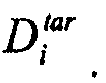

where


- k may be a flow control epoch, k = 1,2,... The overall assigned rate to all M of the
IP gateways 105 may be
- The assigned rate for the first N - 1 NRT priority queues may be

- For N-th priority queue, the assigned rate may be

- β may be a configurable parameter, 0 < β ≤ 1. When ΔD > 0 or ΔDi > 0, the default value of β may be 0.25 otherwise, β = 1.
- The packet delay may be measured either for each individual priority queue or averaged over the priority queues. The weights wi of the priority queues may not reflect the practical traffic mix, but may be used for QoS provisioning. For example, the weight of
priority 1 traffic may be 0.8, butpriority 1 traffic may usually be less than 30% of all of theNRT traffic 201, so such a bandwidth allocation may provide more bandwidth than is needed to high priority traffic. The unused bandwidth may be assigned to lower priority traffic by a cross-priority scheduling algorithm run by, for example, themulti-class scheduling module 208. - The resultant output of the calculation of the overall rate allocation may be λ = [λ1,...,λN], where

IP gateways 105, and [λ1,...,λN] may represent the assigned overall rate for each priority. - In
block 503, bandwidth allocations for individual IP gateways may be calculated. A matrix R = {Rij} may be the demand rate and G = {Gij} may be the grant rate, i = 1,..., N, and j = 1,..., M, where M and N may represent the number of theIP gateways 105 and the number of priorities, respectively, serviced by thegateway 101/CRO. The default value for N may be 4. The demand rate R may be determined by NRTdemand determination module 206, as discussed inFIG. 4 . - λ = [λ1,...,λN] may be the assigned rate for each priority queue, where

block 502. If the total assigned rate is larger or equal to the total amount of demand, for example,

then Gij = ηRij, i = 1,..., N, j = 1,..., M, so every grant is increased such that the excess rate is handed out proportionally to the demand. - If the total demand rate is larger than the total assigned rate, but not exceeded by a certain percentage, for example,

- For
priorities 1 to N,


- The rates assigned to the
IP gateways 105 may be balanced.
gateway 101. Assignment of the residual rate to the unfilled set may be based on a weighted round robin, until all of the residual rate has been assigned. The weighted round robin may work according to
where ϕ i may be a re-configured weight for the round-robin. Whenever a priority demand is fulfilled, the priority demand may be taken out from the weighted round-robin and ϕ i may be updated. Alternatively, a simple round-robin may also be used for assigning the residual rate. -

gateways 105 may be

individual IP gateway 105. - G = {Gij}, i = 1,..., N, j = 1,..., M, may be the derived assignment matrix with grant rate based on the demand matrix R = {Rij} and the
gateway 101/CRO rate vector λ = [λ1,...,λN]. The columns of G may be the priority based credit assignment to each of theIP gateways 105, and the summation of each column,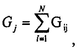
columns IP gateway 105. - If the total demand rate exceeds the total assigned rate by a certain percentage, for example,

priority classes 1 to 3, and service plan based for priority class 4. The default value for θ may be 30%. - For priorities queues with
priority levels 1 to 3, bandwidth allocation may be done as if the demand rate was not greater than total assigned rate. For priority queues with priority level 4, for example, priority queues handling bulk data, uhj may be the number of users in the j-th IP gateway 105, j = 1,..., M, with h-th service plan, h = 1,...,H, where H is the number of service plans.

IP gateway 105. The service plan may be known constant to thegateway 101. - Gi, i = 1,...,3, may be the granted rate for priority queues with
priority levels 1 to 3. The granted rate for priority queues with priority level 4 may be
- The granted rate for each of the
IP gateways 105 may be based on the number of users weighted by the maximum plan rate. Thus, for the IP gateway 105 j, j = 1,..., M,
- When the network is congested, the assignment matrix, G = {Gij}, i = 1,..., N, j = 1,..., M, may be derived based on the demand matrix R = {Rij}, the
gateway 101 rate vector λtotal = [λ1,...,λN] and the user service plan. If a VSAT is in throttled status, the throttled rate may be applied instead of the plan rate for the VSAT. - The
multi-class scheduling module 208 may be any suitable combination of hardware and software in theIP gateways 105 for scheduling data traffic within theIP gateway 105. Upon receiving the allocated bandwidth from thegateway 101, as inFIG. 5 , theIP gateway 105 may schedule the data traffic based on the traffic priority, service plan and physical layer properties of the remote node, or VSAT. At certain intervals, theIP gateway 105 may send the demand request, as calculated by the NRTdemand determination module 206, to thegateway 101, and may receive the assigned rate from thegateway 101, as determined by theresource allocation module 207. Because there may be pre-defined weights associated with each priority queue for thegateway 101, the assigned rate for each of theIP gateways 105 may also consist of a pre-calculated rate for each class of data traffic. Due to conservative allocation for high priority traffic classes at thegateway 101, the assigned rate for a high priority class may be more than the class actually needs. The residual rate can then be used by data traffic from lower priority classes. If the demand for high priority traffic is greater than the assigned rate, the scheduler may not schedule more than the assigned rate. - Each traffic class may consist of spoofed and non-spoofed TCP, as well as UDP flows. The scheduled traffic may be aggregated in a Performance Enhancing Proxy Backbone Protocol (PBP) queue conceptually local to the LAN connected to the
gateway 101. Packets in PBPs may then be forwarded to thegateway 101 priority queues. - In referring to the updating period of the
gateway 101 offered rate as the flow control, or updating period, the flow control interval between each of theIP gateways 105 and thegateway 101 may be 100 ms or more, and the scheduling epoch, or period, may not necessarily follow this period. The time slot for scheduling may be relatively small so that the delay difference, or jitter, introduced by the scheduler is mitigated. A scheduling period of 20 ms may be appropriate for the tradeoff of delay and complexity. ΔT may be the flow control updating period, and may be 100 ms, and Δt may be the scheduling period, and may be 20 ms. With a 20 ms time interval, 20 ms of data based on the offered rate may be transmitted at the class level. At the connection level, a VSAT connection may be allowed to transmit 20 ms of data at an assigned rate. - Different traffic classes may have different scheduling policies subject to the specific quality of service (QoS) requirements. For interactive traffic, which may be the highest priority of the
NRT traffic 201, the network may schedule as much traffic as possible that exists in the system. For background traffic, system throughput may be gained at the cost of extra queuing delay for some connections. Fairness in terms of rate allocation is imposed across the VSATs. Each VSAT may have multiple flows in each class. Themulti-class scheduling module 208 may manage traffic at the VSAT level. -
FIG. 6 depicts an exemplary procedure for multi-class scheduling. Interactive, Multicast (Broadcast), Streaming and Bulk traffic may be schedule at theIP gateways 105 based on the Proportional Fair scheduling scheme. TheRT traffic 202 may be admitted explicitly and, thus, may not part of the multi-class scheduling, since it may be passed through once admitted directly without backpressure. Themulti-class scheduling module 208 may take into account the VSATs' rate plan, channel conditions at the satellite link, and the maximum throughput limit. This may help a VSAT achieve an average throughput proportional to the VSATs rate plan and, if applicable, in favor of those VSATs with good channel conditions. - The proportional fair scheduling scheme may aim to assign bandwidth to VSATs in a way such that the average throughput of a VSAT is proportional to the corresponding service rate plan across the all the VSATs. In addition, a modulation and coding (MODCOD) scheme may be used in bandwidth allocation so that the throughput provided to a terminal, such as a VSAT, may also be proportional to the efficiency of MODCOD at which the terminal is operating.
- In
block 601, a sorting ratio may be calculated. Ai may be the service plan for the i-th user, and the base plan may be A0. The plan ratio may be Ai/A0. - The average throughput for i-th user may be Si and the instant assignment may be Ri, in bytes per scheduling frame. The default value for a scheduling time frame may be 20 ms. The exponential moving average (EMA) for the throughput at time t of VSAT i may be expressed as

where α may be the smoothing factor determining the filter equivalent time constant. If the scheduling period is T, then the time constant τ of EMA may equal
- The throughput vector may be S(t) = [S1(t), S2(t),...,SN(t)], and the allocation rate vector may be R(t) = [R1(t), R2(t),...,RN(t)], where N is the number of VSATs.
- The
multi-class scheduling module 208 may sort the ratio, ri(t) = Si(t)/Ai, at every frame or multiple frames in ascending order, and assign the bandwidth to the VSAT with the smallest ratio. If there are any resource left, the bandwidth may be assigned to the VSAT with second smallest ratio. Greedy filling may continue until the maximum throughput limit is achieved for a certain VSAT or the available bandwidth runs out. Once the bandwidth is assigned, themulti-class scheduling module 208 may update the above average throughputs formula. VSATs that are not scheduled at time t are given zero values. - When MODCOD is considered, the normalized value may be used in calculating the throughput ratio. ACM(j) may be the advanced modulation and coding scheme j, and ACM(0) may be the base MODCOD. The information rate of ACM(0) may be smallest among ACM(i)'s. The MODCOD coefficient may be


- If the MODCOD coefficient is forced to be 1, and the traffic of a VSAT is persistent, then Proportional Fair scheduling scheme may become Round Robin Equal Data; otherwise, it may become Round Robin Equal Time, since with the same air time, the VSAT with the better channel condition can transmit more data.
- In
block 602, the sorting list may be updated. The cost of sorting a large VSAT pool may be expensive. Sorting using proportional fair scheduling scheme may bring the throughput proportion to the desired target starting from the steepest step. The sort list may be updated every frame, since the throughput moving averaging could cover past 10 frames, the performance of the proportional fair scheduling scheme should not be diminished even if the sorting period is a few frames long. - There may be two ways to update the sorting list. The first may be periodic updating, for example, the
multi-class scheduling module 208 may keep on using a sorting list for some time, given that the update duration is sufficiently longer than the sorting time. The second may be continuous updating, i.e., the updated sort list applies to scheduling immediately. For the purpose of efficiency, multiple frame updating may be used. The default updating period may be 2 to 5 frames. - Sorting time may be much smaller than the updating period. However, during sorting, the VSATs' states may be locked, thus the change in active and idle VSATs may be recorded and conveyed to the new sorting list.
- t0 may be the starting time of the sorting, and T_sort may the lock period for sorting. During a sorting interval, the original scheduling sequence may be used. If there are new VSATS associated, or being admitted in, or existing VSATs become idle, the new VSATs may be added to the front of the current scheduling sequence. The idle VSATs may be moved out from the sorting list. If no VSATs move in or out, the scheduling link list may stay unchanged during the interval. When a new sort list comes into use, the sort list may be updated by adding newly arrived VSATs and removing the idled ones during the past T_sort time.
- At any time t, bandwidth allocation may be based on the current sort list, allowing a VSAT on top of the sort list to aggressively use bandwidth until either a max rate limit is reached or all the packets in the VSAT's data queue are served. The remaining bandwidth may then be assigned to the next VSAT in the sort list. The same sort list may apply to each priority level of traffic, but there may be different end positions in each frame. This may be repeated in each priority level in Round Robin fashion until a new updated sort list comes into use.
- In
block 603, throughput limitations may be managed. The maximum throughput during a certain period of time may be capped for a VSAT based on the VSAT's service rate plan. The throughput limitation may be managed in every frame or every few frames. This may be achieved by a token bucket like scheme. To avoid unnecessary latency, the bucket size may be set shallow, for example, the period allowing a throughput burst from a VSAT may be small. - R0 (bits/sec) may be the terminal plan rate, T0 (ms) may be the scheduling frame and B0 may be the available bandwidth for scheduling, or tokens in the bucket. The token bucket scheme may allow up to B0=(K+1)*R0*T0 amount of data burst to be scheduled at one time, where K may be the number of frames allowed for accumulating assigned rate.
- At each frame, the scheduler may assign R0*T0 amount of credit, or rate, to the bucket, while the
multi-class scheduling module 208 may de-queue up to B0 amount of data from the particular data queues of one VSAT. The limiting period may be set to K frames (perceived as bucket size), where K may be a configurable parameter with default value of 1. - At the system level, a certain amount of bandwidth may be reserved for one priority, but at an individual VSAT, the VSAT's own high priority traffic may block access to bandwidth for the VSAT's lower priority traffic classes. Bucket splitting may be used to avoid this.
- The initial credit in the bucket may be B0(t). For
priority level 1,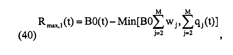
priority level 1 queue, wj may be a pre-assigned weight for priority j class, M may be the number of priorities, and qj(t) may be the amount of data in the corresponding j-th priority queue for the specific VSAT. - A generic formula for the throughput limit of priority i for a particular VSAT may be

where Rmax,i(t) ≥ 0, Aj(t) may be the actual scheduled traffic (allocated bandwidth) for j-th priority at t. - If the bandwidth allocated for a certain priority level is not used up, the bandwidth may be used for subsequent priority classes. If the bandwidth allocated for one frame is not used up, the bandwidth may be carried over to the next frame. However, leftover bandwidth may not be carried over across the boundary of a flow control period.
- For the very last frame of a flow control period, if there is leftover bandwidth from the lowest priority class, and if one or more higher priority classes have run out the allocated bandwidth during this frame, then the
multi-class scheduling module 208 may need to go through a second pass to allow the higher priority classes to utilize the leftover bandwidth. - Because demand from each priority is taken care in the bandwidth allocation from the
gateway 101, as determined by theresource allocation module 207, the allocated bandwidth to each priority of one of theIP gateways 105 may reflect both the demand and weighting. The allocated bandwidth to low priority traffic may be mostly fulfilled, especially when there is no leftover bandwidth from high priority classes. Therefore, the probability that a high priority class (e.g., interactive) is underserved while a low priority class has leftover bandwidth may be very small, and a second pass may not be needed. - The priority
queue servicing module 209 may be any suitable combination of hardware and software at thegateway 101 to provide priority queue servicing for both theRT traffic 202 and certain classes of theNRT traffic 201. The DVB-S2 air interface may not specify a dedicated channel for theRT traffic 202. To provide differentiated and satisfactory quality of service for theRT traffic 201, including traffic for VoIP and video conferencing, and for certain classes ofNRT traffic 201 with stringent latency requirement, the priorityqueue servicing module 209 may run at thegateway 101 and may improve latency performance while maintaining high spectrum utilization. - At the outroute of the satellite network, traffic data from
multiple IP gateways 105 may be multiplexed at thegateway 101 before transmission via the DVB-S2 air interface, such as theRFT 106. Traffic classified into different priorities in theIP gateways 105 may be multiplexed into several priority queues in thegateway 101. The data packets at thegateway 101 may be further packed in DVB-S2 code blocks based on certain modulation and coding schemes before broadcasting. To efficiently use the wireless spectrum, data packets being sent to different remote locations may be organized by an enhanced code rate organizer (CRO) so that each code block includes data with the same modulation and coding scheme. - The enhanced CRO may include two groups of queues, with each queue associated with a certain modulation and coding scheme. Each queue may be referred to as MODCOD queue. One of the groups of queues may be for the
RT traffic 202, and the other group of queues may be for theNRT traffic 201. The queues for theRT traffic 202 may also handle latency sensitive portions of theNRT traffic 201. - A weighted fair queue algorithm may be used to feed the CRO with priority traffic classes coming from the
IP gateways 105. The weighted fair queue algorithm may apply pre-assigned priority weights to prevent provisioning for high priority classes and starvation for low priority classes. -
Fig. 7 depicts an exemplary queuing architecture. Specially formatted IP packets may be passed from theIP gateway 105 to thegateway 101 and be processed through thegateway 101 IP stack and placed in an input LANDriver Buffer Queue 704. The IP packets may be fragmented and may need to be reassembled. Thegateway 101Input Thread 701, including aReceiving Module 703, may be software on thegateway 101 that reads and reassembles incoming packets based upon the pre-assigned priority type, and moves the packets into thecorresponding priority queue 705. - A
processing module 706 and a coderate organizer module 707 may operate in anOutput Thread 702, and may handle queue servicing and final DVB-S2 code block formation. In addition to thepriority queues 705, that hold the re-assembled packets, the queuing architecture may include afast block queue 708, two sets of queues each referred to as a MODCOD group,MODCOD group # 1 711 andMODCOD group # 2 712, and aCode Block Queue 709, which may be used to feed the DVB-S2 code blocks to theSGM Modulator cards 710 for physical layer transmission on the outroute. - The
fast block queue 708 may be used for system traffic, may have the highest priority and may use the most robust MODCOD. The two MODCOD groups may each have a set of queues for each of the MODCODs supported in the system. TheMODCOD group # 1 711 may be used strictly for theRT traffic 202 and the highest priority traffic other than system traffic. All lower priority traffic, such as theNRT traffic 201, may be queued in theMODCOD group # 2 712 queues. - Packets in the
priority queues 705 may be sorted via MODCOD queue operation and then further moved into theCode Block Queue 709 before being transmitted. One parameter of the queuing architecture may be the value representing the target amount of data, represented in time, which may be intended to be maintained within theCode Block Queue 709. For example, if this value is 15 ms, then the queue servicing software may attempt to keep nominally 15 ms of code block data in thisCode Block Queue 709. This may serve as a driver for timing in thegateway 101Output Thread 702. TheProcessing Module 706 may serve as a slave to the Code Rate Organizer (CRO) 707 by extracting packets from thepriority queues 705 and if needed formatting and providing the packets to theCRO 707. Alternatively, the packets may be sorted into the correct MODCOD queue depending on the traffic and MODCOD type. The highest priority and RT packets may be processed and placed in the MODCOD queues associated withMODCOD group # 1 711, while the remaining priority packets may be stored inMODCOD group # 2 712. - The
Code Rate Organizer 707 of thegateway 101Output Thread 702 may have the critical logic for servicing the queues within the MODCOD groups and satisfying delay and jitter requirements within the context of thegateway 101. Incoming traffic fromIP gateways 105 to thegateway 101 may include both theNRT traffic 201 and theRT traffic 202. The RT packets may be stored within an RT priority queue, while NRT packets may be stored within NRT priority queues. Each packet may have a MODCOD indicator which may reflect the channel condition at the destination VSAT. The packets in thepriority queues 705 may be packed into DVB-S2 code blocks in thecode block buffer 204 for physical layer transmission. The transmission of code blocks in thecode block buffer 204 may be driven by the symbol rate. - The
CRO 707 may organize the packets from thepriority queues 705 into thecode block buffer 204 for efficient transmission. The packets with the same MODCOD may be put into a single code block. In addition, theCRO 707 may also ensure that packets with stringent delay or jitter requirement are scheduled for transmission with a desired quality of service. - The packets in the
priority queues 705 may be organized before being put in to thecode block buffer 204. The MODCOD queues may be used for this purpose. There may be two MODCOD groups,MODCOD group # 1 711, for theRT traffic 202, theMODCOD group # 2 712, for theNRT traffic 201, each with the same number of MODCOD queues. Each MODCOD queue may represent certain type of modulation and coding scheme. The number of MODCOD queues in each group may equal the number of MODCOD schemes that are applied, and the MODCOD queues in each group are identical. The MODCOD queues may store the pointers that refer to the packets in thepriority queues 705. There may be no actual data transfer between thepriority queues 705 and MODCOD queues. The operation of a MODCOD queue may be first-in-first-out (FIFO). - To dequeue the
RT traffic 202 from thepriority queues 705 to the MODCOD queue whenever a packet arrives at the RT priority queue, a pointer to the packet may be packed into a corresponding MODCOD queue based on the packet's MODCOD indicator. To dequeue theNRT traffic 201, fulfilling the MODCOD queue may be periodic or event triggered based on thecode block buffer 204 status. In thecode block buffer 204, there may be threshold, B0, which may represent the total amount of data stored incode block buffer 204. A larger B0 may result in longer packet delays in thecode block buffer 204, and a small B0 may cause spectrum under-utilization. B0 may be determined based on the equivalent average delay. By default, thecode block buffer 204 threshold may be set to 15 ms worth of data. B(t) may be the amount of data in thecode block buffer 204 at time t, and ΔB(t) = B0 - B(t), or residual capacity. - For the
RT traffic 202, the dequeuing from the RT priority queue toMODCOD group # 1 711 may be continuous regardless of ΔB(t). For theNRT traffic 202, thecode block buffer 204 threshold B0 may be, for example, 15 ms worth of data by default. When ΔB(t) ≤ 0, no dequeuing of theNRT traffic 202 from lower priority queues toMODCOD group # 2 712 queues may occur. When ΔB(t) > 0, there may be up to ΔB(t) worth of data from thepriority queues 705 moved toMODCOD group # 1 711 orMODOCD group # 2 712 queues. - The dequeuing of ΔB(t) worth of data from the NRT priority queues into MODCOD groups may be based on weighted queuing.
Priority level 1 traffic, such as interactive traffic, may be either moved to theMODCOD group # 1 711, or to theMODCOD group # 2 712. Interactive traffic may more often be dequeued to theMODCOD group # 1 711, along with theRT traffic 202. Time t may be discrete, so a periodic closed loop, for example, every 5 ms, may be sufficient. For event triggers, the dequeuing of thepriority queue 705 may not happen until ΔB(t) reaches a certain amount, such as, for example, 5ms worth of data. - When the data, by way of pointers to the data, is packed into the MODCOD queues, events may be generated to trigger the movement of data from MODCOD groups to the
code block buffer 204. The events causing the formation of a code block may be the accumulations of a sufficient amount of data to form a code block and the expiration of timer. The code block formation event may signal that there is enough data in a MODCOD queue to form a DVB-S2 code block using one MODCOD scheme. There may be a timer associated with packets of each priority level. The timer of a MODCOD queue may be adjusted based on the first packet of a certain priority in the MODCOD queue. For example, if an interactive packet is placed in the front of MODCOD queue, the timer of this MODCOD queue may be associated with this interactive packet. When the timer expires, the data in the MODCOD queue, together with some data that can be borrowed from other MODCOD queues, may be used to form a code block and be moved into thecode block buffer 204. The timer may be set to, for example, 15 ms by default, for packets from theRT traffic 202 and interactive packets from theNRT traffic 201. For lower priority packets from theNRT traffic 201, the timer may be longer, for example, 50 ms up to 200 ms. - When a timer expires, there may not be enough data to form a code block. In this case, borrowing between MODCOD queues may occur. Borrowing can happen inside a MODCOD group or across the two MODCOD groups. Borrowing may first be applied across MODCOD queues with the same MODCOD scheme. For example, if an
MODCOD group # 1 711 queue's timer expires and there is insufficient data to form a code block, data in the same level MODCOD queue inMODOC group # 2 712 may be borrowed, and vice versa. - If there is not enough data to be borrowed in a MODCOD queue of the same level, the data from lower MODCOD level queues in the same and the other MODCOD group may be used. For example, if a code block of 3/4 QPSK is not fulfilled, data may be borrowed from a 4/5 QPSK MODCOD queue, but not a 1/2 QPSK queue. Between the two MODCOD groups, data should be borrowed from the
MODCOD group # 1 711 first, and theMODCOD group # 2 712 second. - If there is no qualifying data that can be borrowed, a code block may be filled with dummy packets, or null data.
- The
gateway 101 may poll the code block buffer at certain frequency, for example, every 5ms, or use an event trigger which is based on a threshold of current buffer size. The remaining buffer size may be compared with thecode block buffer 204 capacity, buffer size B0, and the difference may be calculated as residual capacity. - The residual capacity, ΔB(t), may be used to fetch the packets from the
priority queues 705 into the MODCOD queue groups. Such queue serving may follow the same timing as the polling schedule. There may be one RT and M NRT priority queues. The queue size for the RT queue may be qRT and the queue size for the NRT queues may be qNRT,i, i = 1,...M. W = {wi}, i = 1,..., M may be the weights associated with the NRT queues. The queue servicing procedure may be accomplished in two ways. - In the first way, the
RT traffic 202 may be dequeued from thepriority queue 705 to theMODCOD group # 1 711, regardless of the status of thecode block buffer 204. For the NRT priority queues, XNRT = ΔB(t). Data with a priority level of 1 may be dequeued into theMODCOD group # 1 711, while theother priority queues 705 for theNRT traffic 201 may be sent to theMODCOD group # 2 712. To dequeue the NRT queues to the MODCOD groups, for the i thlevel NRT queue, i = 1,..., M, XNRT,i = wi · XNRT may be pre-calculated. If qNRT,i ≥ XNRT,i, XNRT,i may be dequeued from the i-th queue to the MODCOD queues.
Otherwise, qNRT,i may be dequeued from the i-th queue to the MODCOD queues. The remaining capacity, wi · XNRT - qNRT,i, may be attributed to the (i+1)-th priority queue, for example, XNRT,i+1 = XNRT,i+1 + (wi · XNRT - qNRT,i). This may be repeated until all of the NRT queues have been served. - In the second way, dequeuing the
RT traffic 202 may be based on the availablecode block buffer 204 capacity, so X = ΔB(t). If X ≤ qRT, then X worth of data may be dequeued from the RT queue to theMODCOD group # 1 711, and no data may be dequeued from the NRT queues. Otherwise, qRT worth of data may be dequeued from the RT queue to theMODCOD group # 1 711, XNRT = X - qRT may be updated, and data may dequeued from the NRT queues to the MODCOD queues. For the i thlevel NRT queue, i = 1,..., M, XNRT,i = wi · XNRT may be pre-calculated, and, until all of the NRT queues are served, if qNRT,i ≥ XNRT,i, XNRT,i worth of data my be dequeued from the i-th queue to the MODCOD queues, otherwise qNRT,i worth of data may be dequeued from the i-th queue to the MODCOD queues and the remaining capacity wi · XNRT - qNRT,i may be attributed to (i+1)-th queue, XNRT,i+1 = XNRT,i+1 + (wi · XNRT - qNRT,i). - The two ways of dequeuing data may become equivalent if the code block threshold for the
RT traffic 202 is very large. - As used herein, a "computer" or "computer system" may be, for example and without limitation, either alone or in combination, a personal computer (PC), server-based computer, main frame, server, microcomputer, minicomputer, laptop, personal data assistant (PDA), cellular phone, pager, processor, including wireless and/or wire line varieties thereof, and/or any other computerized device capable of configuration for receiving, storing and/or processing data for standalone application and/or over a networked medium or media. Examples of communication media that can be employed include, without limitation, wireless data networks, wire line networks, and/or a variety of networked media.
- Computers and computer systems described herein may include operatively associated computer-readable media such as memory for storing software applications used in obtaining, processing, storing and/or communicating data. It can be appreciated that such memory can be internal, external, remote or local with respect to its operatively associated computer or computer system. Memory may also include any means for storing software or other instructions including, for example and without limitation, a hard disk, an optical disk, floppy disk, DVD, compact disc, memory stick, ROM (read only memory), RAM (random access memory), PROM (programmable ROM), EEPROM (extended erasable PROM), and/or other like computer-readable media.
- In general, computer-readable media may include any medium capable of being a carrier for an electronic signal representative of data stored, communicated or processed in accordance with embodiments of the present invention. Where applicable, method steps described herein may be embodied or executed as instructions stored on a computer-readable medium or media.
- It is to be understood that the figures and descriptions of the present invention have been simplified to illustrate elements that are relevant for a clear understanding of the present invention, while eliminating, for purposes of clarity, other elements. Those of ordinary skill in the art will recognize, however, that these and other elements may be desirable. However, because such elements are well known in the art, and because they do not facilitate a better understanding of the present invention, a discussion of such elements is not provided herein. It should be appreciated that the figures are presented for illustrative purposes and not as construction drawings. Omitted details and modifications or alternative embodiments are within the purview of persons of ordinary skill in the art.
- It can be appreciated that, in certain aspects of the present invention, a single component may be replaced by multiple components, and multiple components may be replaced by a single component, to provide an element or structure or to perform a given function or functions. Except where such substitution would not be operative to practice certain embodiments of the present invention, such substitution is considered within the scope of the present invention.
- The examples presented herein are intended to illustrate potential and specific implementations of the present invention. It can be appreciated that the examples are intended primarily for purposes of illustration of the invention for those skilled in the art. The diagrams depicted herein are provided by way of example. There may be variations to these diagrams or the operations described herein without departing from the spirit of the invention. For instance, in certain cases, method steps or operations may be performed or executed in differing order, or operations may be added, deleted or modified.
- Furthermore, whereas particular embodiments of the invention have been described herein for the purpose of illustrating the invention and not for the purpose of limiting the same, it will be appreciated by those of ordinary skill in the art that numerous variations of the details, materials and arrangement of elements, steps, structures, and/or parts may be made within the principle and scope of the invention without departing from the invention as described in the following claims.
Claims (14)
- A method for traffic management and resource allocation on a shared access network comprising:estimating a bandwidth capacity of a gateway;determining a demand rate of an IP gateway;allocating bandwidth to the IP gateway based on at least one of the demand rate, traffic priority, and traffic weighting;allocating bandwidth to the IP gateway in advance of demand when excess bandwidth is available;scheduling traffic at the IP gateway based on at least one of traffic priority, service plan of a VSAT, and physical layer properties of the VSAT; andperforming priority queue servicing of traffic at a gateway using a real time traffic priority queue, a non-real time traffic priority queue, at least two modulation and coding queue groups, and a code block queue.
- The method of claim 1, wherein estimating a bandwidth is done according to the equation:

where ΔT is the IP gateway-gateway flow control update period, Δt is the sampling interval of code blocks from a MODCOD queue group, N is the number of types of code blocks, Ki is the number of types of code blocks during the period of ΔT, Mi is the number of effective bits per symbol of type i, bCB is the total number of bits in one code block, S is the total number of symbols for all the code blocks in ΔT and is calculated as

- The method of claim 1, wherein determining a demand rate of an IP gateway is done according to the equations:


where ΔT is a predefined flow control update period with M measurement time frames, N is the number of active flows,
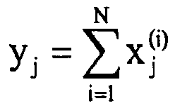


Y k+1 = β · Yk + (1-β).Y k is the moving average of the mean Yk, (Y k+1)std = β·(Yk)std + (1 - β)·(Y k)std is the moving average of the standard deviation (Yk)std, β is a weighing factor, 0 < β < 1,

Y k)std is a demand margin for all the flows of interactive traffic class in the IP gateway being serviced by a particular carrier stream,Y k+1 is a predicted bandwidth usage for (k+1)-th update cycle, Ymin is a lower bound on predicted bandwidth usage, Ymax is an upper bound on predicted bandwidth usage, Li(k) is a recent updated queue size of a VSAT i, Li(k)=Li(k-1)+λi(k)Δk-µi(k)Δk=Li(k-1)+λi(k)Δk-Ai(k),


- The method of claim 1, wherein allocating bandwidth to the IP gateway is done according to the equations:where Nt is the number of data packets put into MODCOD queues during the period of t-Δt to t, davg(t) is an average packet delay at time t,
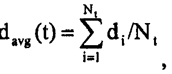


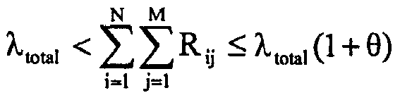

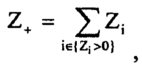


- The method of claim 1, wherein scheduling traffic at the IP gateway further comprises:calculating a sorting ratio according to the equation:


- The method of claim 5, further comprising:managing throughput limitations according with a token bucket scheme according to the equation:

where R0 (bits/sec) is a terminal plan rate, T0 is a scheduling frame, B0 is available bandwidth for scheduling where Rmax,1(t) is a maximum amount of data that can be de-queued from a priority level 1 queue, wj is a pre-assigned weight for priority j class, M is a number of priorities, qj(t) is an amount of data in the corresponding j-th priority queue for the specific VSAT, Aj(t) and is actual allocated bandwidth for a j-th priority at t. - A system for traffic management and resource allocation on a shared access network comprising:an IP gateway; anda gateway,wherein the gateway estimates a bandwidth capacity of the gateway, the IP gateway determines a demand rate of the IP gateway, determining a demand rate of an IP gateway, the gateway allocates bandwidth to the IP gateway based on the demand rate, traffic priority, and traffic weighting, the IP gateway schedules traffic based on traffic priority, a VSAT service plan, a physical layer properties of the VSAT, and the gateway performs priority queue servicing at the gateway,
- The system of claim 7, wherein the gateway comprises:a real time traffic priority queue, a non-real time traffic priority queue, at least two modulation and coding queue groups, and a code block queue.
- The method of claim 7, wherein the gateway estimates the bandwidth capacity according to the equation:

where ΔT is the IP gateway-gateway flow control update period, Δt is the sampling interval of code blocks from a MODCOD queue group, N is the number of types of code blocks, Ki is the number of types of code blocks during the period of ΔT, Mi is the number of effective bits per symbol of type i, bCB is the total number of bits in one code block, S is the total number of symbols for all the code blocks in ΔT and is calculated as
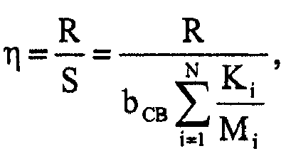
- The system of claim 7, wherein the IP gateway determines the demand according to the equations:


where ΔT is a predefined flow control update period with M measurement time frames, N is the number of active flows,


Y k+1 = β·Yk+(1-β)·Y k is the moving average of the mean Yk, (Y k+1)std = β·(Yk)std+(1-β)·(Y k)std is the moving average of the standard deviation (Yk)std, β is a weighing factor, 0 < β < 1,

Y k)std is a demand margin for all the flows of interactive traffic class in the IP gateway being serviced by a particular carrier stream,Y k+1 is a predicted bandwidth usage for (k+1)-th update cycle, Ymin is a lower bound on predicted bandwidth usage, Ymax is an upper bound on predicted bandwidth usage, Li(k) is a recent updated queue size of a VSAT i, Li(k)=Li(k-1)+λi(k)Δk-µi(k)Δk=Li(k-1)+λi(k)Δk-Ai(k),


- The system of claim 7, wherein the gateway allocated bandwidth to the IP gateway according to the equations:where Nt is the number of data packets put into MODCOD queues during the period of t - Δt to t, davg(t) is an average packet delay at time t,


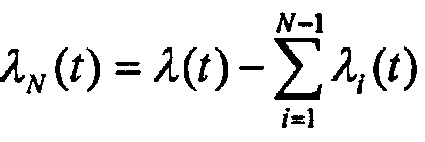





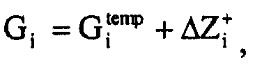


- The system of claim 7, wherein IP gateway schedules traffic by calculating a sorting ratio according to the equation:

Ai is a service plan for the i-th user, A0 is a base plan, Si is an average throughput for i-th user, Ri is an instant assignment in bytes per scheduling frame, an exponential moving average for the throughput at a time t of a V SAT i is Si(t) = α·Ri+(1-α)·Si(t-1), α is a smoothing factor determining a filter equivalent time constant, T is a scheduling period, τ is a time constant of the exponential moving average,

- The system of claim 12, wherein the IP gateway schedules traffic by managing throughput limitations according with a token bucket scheme according to the equation:

where R0 (bits/sec) is a terminal plan rate, T0 is a scheduling frame, B0 is available bandwidth for scheduling where Rmax,1(t) is a maximum amount of data that can be de-queued from a priority level 1 queue, wj is a pre-assigned weight for priority j class, M is a number of priorities, qj(t) is an amount of data in the corresponding j-th priority queue for the specific VSAT, Aj(t) and is actual allocated bandwidth for a j-th priority at t. - A method for traffic management and resource allocation on a shared access network comprising:estimating a bandwidth capacity of a gateway;determining a demand rate of an IP gateway;allocating bandwidth to the IP gateway based on at least one of the demand rate, traffic priority, and traffic weighting;allocating bandwidth to the IP gateway in advance of demand when excess bandwidth is available;scheduling traffic at the IP gateway based on at least one of traffic priority, service plan of a terminal, and physical layer properties of the terminal; andperforming priority queue servicing of traffic at a gateway using a real time traffic priority queue, a non-real time traffic priority queue, at least two modulation and coding queue groups, and a code block queue.
Applications Claiming Priority (1)
| Application Number | Priority Date | Filing Date | Title |
|---|---|---|---|
| US13/306,199 US8660006B2 (en) | 2011-11-29 | 2011-11-29 | Method and system for traffic management and resource allocation on a shared access network |
Publications (2)
| Publication Number | Publication Date |
|---|---|
| EP2600553A1 true EP2600553A1 (en) | 2013-06-05 |
| EP2600553B1 EP2600553B1 (en) | 2019-05-22 |
Family
ID=47355835
Family Applications (1)
| Application Number | Title | Priority Date | Filing Date |
|---|---|---|---|
| EP12194700.6A Active EP2600553B1 (en) | 2011-11-29 | 2012-11-28 | Method and system for traffic management and resource allocation on a shared access network |
Country Status (3)
| Country | Link |
|---|---|
| US (2) | US8660006B2 (en) |
| EP (1) | EP2600553B1 (en) |
| BR (1) | BR102012030343B1 (en) |
Cited By (5)
| Publication number | Priority date | Publication date | Assignee | Title |
|---|---|---|---|---|
| WO2015092074A1 (en) * | 2013-12-20 | 2015-06-25 | Avanti Broadband Limited | Internet access via satellite |
| CN105511311A (en) * | 2015-11-30 | 2016-04-20 | 上海卫星工程研究所 | High-efficiency remote-sensing satellite multi-system cooperation integration control method |
| WO2016193142A1 (en) * | 2015-05-29 | 2016-12-08 | Avanti Communications Group Plc | Satellite communication |
| WO2018067392A1 (en) * | 2016-10-06 | 2018-04-12 | Hughes Network Systems, Llc | Method and system in a satellite network for offering subscriber service levels based on signal fade by adaptive modulation and coding. |
| WO2025193473A1 (en) * | 2024-03-13 | 2025-09-18 | Kratos Integral Holdings Llc | Queue management for packet transmission in satellite communication system |
Families Citing this family (85)
| Publication number | Priority date | Publication date | Assignee | Title |
|---|---|---|---|---|
| US7675854B2 (en) | 2006-02-21 | 2010-03-09 | A10 Networks, Inc. | System and method for an adaptive TCP SYN cookie with time validation |
| US8966110B2 (en) * | 2009-09-14 | 2015-02-24 | International Business Machines Corporation | Dynamic bandwidth throttling |
| US9960967B2 (en) | 2009-10-21 | 2018-05-01 | A10 Networks, Inc. | Determining an application delivery server based on geo-location information |
| US9094364B2 (en) | 2011-12-23 | 2015-07-28 | A10 Networks, Inc. | Methods to manage services over a service gateway |
| US8782221B2 (en) | 2012-07-05 | 2014-07-15 | A10 Networks, Inc. | Method to allocate buffer for TCP proxy session based on dynamic network conditions |
| US20140153388A1 (en) * | 2012-11-30 | 2014-06-05 | Hewlett-Packard Development Company, L.P. | Rate limit managers to assign network traffic flows |
| US9531846B2 (en) | 2013-01-23 | 2016-12-27 | A10 Networks, Inc. | Reducing buffer usage for TCP proxy session based on delayed acknowledgement |
| US9060293B1 (en) * | 2013-01-25 | 2015-06-16 | Sprint Spectrum L.P. | Reducing wireless communication signaling overhead |
| US9391749B2 (en) * | 2013-03-14 | 2016-07-12 | Ashwin Amanna, III | System and method for distributed data management in wireless networks |
| US9197572B2 (en) * | 2013-03-15 | 2015-11-24 | The Regents Of The University Of California | Throughput enabled rate adaptation in wireless networks |
| US10027761B2 (en) | 2013-05-03 | 2018-07-17 | A10 Networks, Inc. | Facilitating a secure 3 party network session by a network device |
| US10230770B2 (en) | 2013-12-02 | 2019-03-12 | A10 Networks, Inc. | Network proxy layer for policy-based application proxies |
| US10020979B1 (en) * | 2014-03-25 | 2018-07-10 | A10 Networks, Inc. | Allocating resources in multi-core computing environments |
| US9806943B2 (en) | 2014-04-24 | 2017-10-31 | A10 Networks, Inc. | Enabling planned upgrade/downgrade of network devices without impacting network sessions |
| US9992229B2 (en) | 2014-06-03 | 2018-06-05 | A10 Networks, Inc. | Programming a data network device using user defined scripts with licenses |
| US10129122B2 (en) | 2014-06-03 | 2018-11-13 | A10 Networks, Inc. | User defined objects for network devices |
| US9986061B2 (en) | 2014-06-03 | 2018-05-29 | A10 Networks, Inc. | Programming a data network device using user defined scripts |
| CN104022966B (en) * | 2014-06-24 | 2017-04-19 | 河北工程大学 | ONU internal scheduling method for guaranteeing QoS in PON based on NC |
| US10110300B2 (en) * | 2014-09-08 | 2018-10-23 | Hughes Network Systems, Llc | Bandwidth management across logical groupings of access points in a shared access broadband network |
| US10700772B2 (en) | 2014-09-08 | 2020-06-30 | Hughes Network Systems, Llc | Dynamic bandwidth management with spectrum efficiency for logically grouped terminals in a broadband satellite network |
| US10020901B2 (en) * | 2014-09-29 | 2018-07-10 | Hughes Network Systems, Llc | Inter-gateway interference management and admission control for a CDMA satellite communications system |
| US9609543B1 (en) * | 2014-09-30 | 2017-03-28 | Sprint Spectrum L.P. | Determining a transmission order of data packets in a wireless communication system |
| US9628168B2 (en) * | 2015-02-26 | 2017-04-18 | Space Systems/Loral, Llc | Dynamic link adaption and/or dynamic allocation of communication resources of a communication system based on external interference information received from external interference information sources |
| US10581976B2 (en) | 2015-08-12 | 2020-03-03 | A10 Networks, Inc. | Transmission control of protocol state exchange for dynamic stateful service insertion |
| US10243791B2 (en) | 2015-08-13 | 2019-03-26 | A10 Networks, Inc. | Automated adjustment of subscriber policies |
| US20190008859A1 (en) | 2015-08-21 | 2019-01-10 | Acerta Pharma B.V. | Therapeutic Combinations of a MEK Inhibitor and a BTK Inhibitor |
| US10609616B2 (en) | 2015-12-22 | 2020-03-31 | Alfred Consulting LLC | System and method for using mobility information in heterogeneous networks |
| JP6514100B2 (en) * | 2015-12-28 | 2019-05-15 | 株式会社東芝 | Communication apparatus, communication system and network management method |
| US10318288B2 (en) | 2016-01-13 | 2019-06-11 | A10 Networks, Inc. | System and method to process a chain of network applications |
| EP3866415B1 (en) * | 2016-02-19 | 2022-11-02 | ViaSat Inc. | Methods and systems for multi-level network capacity allocation |
| US11072356B2 (en) | 2016-06-30 | 2021-07-27 | Transportation Ip Holdings, Llc | Vehicle control system |
| US10814893B2 (en) | 2016-03-21 | 2020-10-27 | Ge Global Sourcing Llc | Vehicle control system |
| US10921458B2 (en) | 2016-06-15 | 2021-02-16 | Hughes Network Systems, Llc | Apparatus and methods for interference mitigation by satellite networks |
| US10243801B2 (en) * | 2016-06-30 | 2019-03-26 | Hughes Networking Systems, LLC | Method and system for distributive flow control and bandwidth management in a network |
| CN106452555A (en) * | 2016-08-31 | 2017-02-22 | 华东师范大学 | Multi-path optimization algorithm planning method based on medium and low earth orbit satellite network |
| EP3520246B1 (en) | 2016-09-30 | 2024-05-22 | Hughes Network Systems, LLC | System and method for bandwidth profile based allocation and management of a time-varying topology network |
| CN106411607B (en) * | 2016-11-04 | 2019-08-20 | 锐捷网络股份有限公司 | Flow transmission control method and device based on VXLAN network |
| CN106507485A (en) * | 2016-12-09 | 2017-03-15 | 北京邮电大学 | A quality-of-service-oriented wireless layered multicast transmission resource allocation method |
| CN112184192B (en) | 2016-12-12 | 2024-08-30 | 创新先进技术有限公司 | Resource allocation method and device and electronic payment method |
| US10389835B2 (en) | 2017-01-10 | 2019-08-20 | A10 Networks, Inc. | Application aware systems and methods to process user loadable network applications |
| US10205804B2 (en) | 2017-02-01 | 2019-02-12 | Hughes Network Systems, Llc | Methods and systems for enhanced support of TCP options in a TCP spoofed system |
| US10681693B2 (en) | 2017-02-21 | 2020-06-09 | Hughes Network Systems, Llc | System and method for simultaneous FDMA-TDMA channel access |
| CN106921591B (en) * | 2017-03-27 | 2020-05-12 | 西安电子科技大学 | Method for processing critical service burst in airborne navigation electric network |
| US10701713B2 (en) * | 2017-04-11 | 2020-06-30 | Viasat, Inc. | Return link prioritization of selective events on a mobile platform |
| JP6780579B2 (en) * | 2017-05-12 | 2020-11-04 | トヨタ自動車株式会社 | Wireless terminal and communication control method |
| WO2019032747A1 (en) * | 2017-08-08 | 2019-02-14 | Aviat U.S., Inc. | Traffic management for variable bandwidth networks using rsvp |
| US10530394B2 (en) | 2017-10-13 | 2020-01-07 | Hughes Network Systems, Llc | System and method for optimizing forward error correction according to number of simultaneous users |
| US10587560B2 (en) | 2017-11-07 | 2020-03-10 | General Electric Company | Unified real-time and non-real-time data plane |
| CN108347734B (en) * | 2018-01-04 | 2021-11-23 | 西安电子科技大学 | Time-equalization-based resource allocation method in cognitive wireless communication system |
| CN110048964B (en) * | 2018-01-15 | 2023-09-12 | 深圳市中兴微电子技术有限公司 | A business queue shaping method, terminal and storage medium |
| US11063658B2 (en) * | 2018-06-28 | 2021-07-13 | Amazon Technologies, Inc. | Satellite antenna ground station service system |
| CN110830391A (en) * | 2018-08-10 | 2020-02-21 | 阿里巴巴集团控股有限公司 | Resource allocation method and device, cluster system |
| CN109120549B (en) * | 2018-09-07 | 2021-10-19 | 广东工业大学 | A priority-driven handoff optimization method under wireless SDN |
| WO2020056633A1 (en) * | 2018-09-19 | 2020-03-26 | 华为技术有限公司 | Method for estimating network rate and estimation device |
| CN111026519B (en) * | 2018-10-10 | 2023-11-10 | 上海宝信软件股份有限公司 | Distributed task priority scheduling method and system and storage medium |
| CN109639470B (en) * | 2018-11-30 | 2021-10-15 | 四川安迪科技实业有限公司 | VSAT satellite communication system bandwidth allocation method based on star networking |
| CN109617836B (en) * | 2018-12-29 | 2021-08-03 | 中国科学院遥感与数字地球研究所 | Intelligent bandwidth allocation method and allocation system for satellite data transmission |
| CN110535778B (en) * | 2019-08-29 | 2022-09-23 | 河南科技大学 | Transmission rate allocation method for TCP protocol in data center network |
| CN110636014B (en) * | 2019-10-09 | 2022-08-02 | 大连大学 | Satellite network queue scheduling algorithm based on traffic self-similarity characteristic |
| US11589315B2 (en) * | 2019-11-22 | 2023-02-21 | Hughes Network Systems, Llc | Dynamic resizing of a satellite link outroute or forward channel |
| US11108669B2 (en) * | 2019-12-31 | 2021-08-31 | Hughes Network Systems, Llc | Hierarchical multi-tier throughput assignment for a shared throughput satellite network |
| CN111555792A (en) * | 2020-04-08 | 2020-08-18 | 四川华能康定水电有限责任公司 | Emergency Communication System Based on SKYWAN VSAT Satellite Communication Network |
| CN113727389B (en) * | 2020-05-25 | 2025-09-12 | 华为技术有限公司 | Method, device and system for determining bandwidth of transmission service flow |
| CN111682892B (en) * | 2020-06-08 | 2022-07-29 | 凯睿星通信息科技(南京)股份有限公司 | Automatic link establishment method based on service perception of intelligent gateway in satellite communication |
| CN111988242B (en) * | 2020-07-23 | 2023-06-16 | 大连大学 | Hybrid queue scheduling method of heaven-earth integrated intelligent network |
| CN112615647A (en) * | 2020-11-24 | 2021-04-06 | 国网天津市电力公司 | Broadband power line carrier communication cross-layer resource allocation method for power internet of things concurrent mixed service |
| CN113014305B (en) * | 2021-02-23 | 2023-02-03 | 哈尔滨工业大学 | Power-Bandwidth Joint Resource Optimization Method Based on Priority Admission Control |
| CN113315720B (en) * | 2021-04-23 | 2023-02-28 | 深圳震有科技股份有限公司 | A data flow control method, system and device |
| CN113630635A (en) * | 2021-07-30 | 2021-11-09 | 泉州市晟彩光电科技有限公司 | Integrated management method, terminal and storage medium based on multi-region electronic screen |
| CN113890860B (en) * | 2021-11-18 | 2022-07-15 | 深圳大学 | Method, apparatus, and medium for supporting latency-constrained data exchange |
| EP4457954A1 (en) * | 2021-12-28 | 2024-11-06 | Hughes Network Systems, LLC | Satellite system optimization by differentiating application of adaptive coding and modulation |
| CN114499643B (en) * | 2022-01-27 | 2022-11-22 | 中国人民解放军32039部队 | Method and device for allocating equipment resources in satellite ground station and electronic equipment |
| CN114500991B (en) * | 2022-02-10 | 2026-03-10 | 游密科技(深圳)有限公司 | Audio communication feasibility test method and device based on video conference |
| US11936564B2 (en) * | 2022-05-18 | 2024-03-19 | Cisco Technology, Inc. | Dynamically enabling a transport control protocol proxy for satellite networks |
| US11632289B1 (en) | 2022-07-01 | 2023-04-18 | Frontier Communication Holdings, LLC | Optimal placement of aggregator equipment in telecommunication networks |
| CN115696615A (en) * | 2022-09-16 | 2023-02-03 | 中国船舶重工集团公司第七一九研究所 | An embedded LoRaWAN gateway based on just-in-time double buffer queue algorithm |
| CN115225577B (en) * | 2022-09-20 | 2022-12-27 | 深圳市明源云科技有限公司 | Data processing control method and device, electronic equipment and readable storage medium |
| CN115955443B (en) * | 2022-09-29 | 2024-05-17 | 中国联合网络通信集团有限公司 | Resource scheduling method, device and storage medium |
| CN115865833A (en) * | 2022-11-15 | 2023-03-28 | 国网宁夏电力有限公司信息通信公司 | Power service access system and access method based on terminal resource scheduling |
| CN115834724B (en) * | 2022-11-17 | 2024-08-23 | 航天科工空间工程网络技术发展(杭州)有限公司 | A data encapsulation method, computer-readable storage medium and gateway |
| CN118672767B (en) * | 2024-05-23 | 2025-05-16 | 深圳华泓智能有限公司 | Computing power scheduling method and system combining GPU virtualization and AI |
| CN119761752B (en) * | 2024-12-20 | 2026-03-13 | 湖南科技学院 | A heterogeneous data packet scheduling method and system based on time-varying characteristics and priorities |
| CN119421247B (en) * | 2025-01-06 | 2025-04-18 | 成都星联芯通科技有限公司 | Scheduling cycle updating method, earth master station and satellite communication system |
| CN120245010B (en) * | 2025-06-04 | 2025-08-29 | 杭州泛嘉科技有限公司 | Collaborative operation system and method of humanoid robot and robot dog |
| CN121365097B (en) * | 2025-12-22 | 2026-03-17 | 厦门绩牛智能科技有限公司 | Digital one-network financial marketing management method and system |
Citations (3)
| Publication number | Priority date | Publication date | Assignee | Title |
|---|---|---|---|---|
| DE102006025037B3 (en) * | 2006-05-26 | 2007-09-13 | Deutsches Zentrum für Luft- und Raumfahrt e.V. | A resource allocation method in an interactive satellite broadcast network multimedia system |
| US20080049659A1 (en) * | 2006-08-25 | 2008-02-28 | Gilat Satellite Networks Ltd. | Packing Data Over An Adaptive Rate Link |
| US20080298299A1 (en) * | 2006-10-03 | 2008-12-04 | Viasat, Inc. | Upstream resource optimization |
Family Cites Families (2)
| Publication number | Priority date | Publication date | Assignee | Title |
|---|---|---|---|---|
| US7023820B2 (en) * | 2000-12-28 | 2006-04-04 | Nokia, Inc. | Method and apparatus for communicating data in a GPRS network based on a plurality of traffic classes |
| US8526452B1 (en) * | 2009-07-13 | 2013-09-03 | Viasat, Inc. | Quality of service packet scheduler design |
-
2011
- 2011-11-29 US US13/306,199 patent/US8660006B2/en active Active
-
2012
- 2012-11-28 BR BR102012030343-4A patent/BR102012030343B1/en active IP Right Grant
- 2012-11-28 EP EP12194700.6A patent/EP2600553B1/en active Active
-
2014
- 2014-02-21 US US14/186,893 patent/US8929217B2/en active Active
Patent Citations (3)
| Publication number | Priority date | Publication date | Assignee | Title |
|---|---|---|---|---|
| DE102006025037B3 (en) * | 2006-05-26 | 2007-09-13 | Deutsches Zentrum für Luft- und Raumfahrt e.V. | A resource allocation method in an interactive satellite broadcast network multimedia system |
| US20080049659A1 (en) * | 2006-08-25 | 2008-02-28 | Gilat Satellite Networks Ltd. | Packing Data Over An Adaptive Rate Link |
| US20080298299A1 (en) * | 2006-10-03 | 2008-12-04 | Viasat, Inc. | Upstream resource optimization |
Non-Patent Citations (2)
| Title |
|---|
| "Digital Video Broadcasting (DVB); Generic Stream Encapsulation (GSE) implementation guidelines", TECHNICAL SPECIFICATION, EUROPEAN TELECOMMUNICATIONS STANDARDS INSTITUTE (ETSI), 650, ROUTE DES LUCIOLES ; F-06921 SOPHIA-ANTIPOLIS ; FRANCE, vol. BROADCAS, no. V1.2.1, 31 May 2011 (2011-05-31), XP014064621 * |
| COLLINI-NOCKER B ET AL: "Class based scheduling for DVB-S2", SATELLITE AND SPACE COMMUNICATIONS, 2009. IWSSC 2009. INTERNATIONAL WORKSHOP ON, IEEE, PISCATAWAY, NJ, USA, 9 September 2009 (2009-09-09), pages 240 - 243, XP031545947, ISBN: 978-1-4244-4384-0 * |
Cited By (8)
| Publication number | Priority date | Publication date | Assignee | Title |
|---|---|---|---|---|
| WO2015092074A1 (en) * | 2013-12-20 | 2015-06-25 | Avanti Broadband Limited | Internet access via satellite |
| US9831939B2 (en) | 2013-12-20 | 2017-11-28 | Avanti Broadband Limited | Internet access via satellite |
| WO2016193142A1 (en) * | 2015-05-29 | 2016-12-08 | Avanti Communications Group Plc | Satellite communication |
| CN105511311A (en) * | 2015-11-30 | 2016-04-20 | 上海卫星工程研究所 | High-efficiency remote-sensing satellite multi-system cooperation integration control method |
| CN105511311B (en) * | 2015-11-30 | 2018-05-18 | 上海卫星工程研究所 | Efficient remote sensing satellite multisystem coordination with the synthesis control method |
| WO2018067392A1 (en) * | 2016-10-06 | 2018-04-12 | Hughes Network Systems, Llc | Method and system in a satellite network for offering subscriber service levels based on signal fade by adaptive modulation and coding. |
| US10193764B2 (en) | 2016-10-06 | 2019-01-29 | Hughes Network Systems, Llc | Method and system for offering subscriber service plans by adaptive coding and modulation used |
| WO2025193473A1 (en) * | 2024-03-13 | 2025-09-18 | Kratos Integral Holdings Llc | Queue management for packet transmission in satellite communication system |
Also Published As
| Publication number | Publication date |
|---|---|
| US8660006B2 (en) | 2014-02-25 |
| EP2600553B1 (en) | 2019-05-22 |
| US20140169167A1 (en) | 2014-06-19 |
| BR102012030343A2 (en) | 2016-03-29 |
| BR102012030343B1 (en) | 2022-04-12 |
| US20130135996A1 (en) | 2013-05-30 |
| US8929217B2 (en) | 2015-01-06 |
Similar Documents
| Publication | Publication Date | Title |
|---|---|---|
| EP2600553B1 (en) | Method and system for traffic management and resource allocation on a shared access network | |
| EP2600538B1 (en) | Method and system for bandwidth allocation supporting multiple traffic priorities in a satellite network. | |
| US11664888B2 (en) | Dynamic bandwidth management with spectrum efficiency for logically grouped terminals in a broadband satellite network | |
| US10700771B2 (en) | Bandwidth management across logical groupings of access points in a shared access broadband network | |
| US11153786B2 (en) | System and method for bandwidth profile based allocation and management of a time-varying topology network | |
| US7027414B2 (en) | Method, apparatus, and system for identifying and efficiently treating classes of traffic | |
| EP2027681B1 (en) | Mapping services to radio bearers and allocating bandwidth to the radio bearers according to weight values | |
| US6865388B2 (en) | Dynamic queue depth management in a satellite terminal for bandwidth allocations in a broadband satellite communications system | |
| US20040264500A1 (en) | Method and apparatus for policy-based dynamic preemptive scheduling of data transmissions | |
| US20030031141A1 (en) | Scheduling and queue servicing in a satellite terminal for bandwidth allocations in a broadband satellite communications system | |
| EP2600575A1 (en) | Method and system for controlling tcp traffic with random early detection and window size adjustments | |
| US20230164092A1 (en) | Home network resource management | |
| US20110158182A1 (en) | Method and system of packet scheduling | |
| Park et al. | Two-step scheduling scheme to support fairness and QoS in DVB-S2 system. | |
| KR101988476B1 (en) | Effective bandwidth calculating system for assure the QoS of real-time voice in Geostationary Orbit Satellite and method of resource allocation thereof | |
| Xu et al. | Flow control and traffic management for a broadband satellite network | |
| Puttonen et al. | Radio resource management in DVB-RCS2 satellite systems | |
| Devi | Predictive traffic estimation for uplink resource allocation in satellite communications | |
| Narula‐Tam et al. | QOS considerations for future military satcom networks with link layer dynamic resource allocation | |
| Ibikunle | Enhancements of CFDAMA protocol for multi-service applications in a GEO broadband satellite network | |
| Narula-Tam et al. | Resource request strategies for dynamic resource allocation in a satellite network |
Legal Events
| Date | Code | Title | Description |
|---|---|---|---|
| PUAI | Public reference made under article 153(3) epc to a published international application that has entered the european phase |
Free format text: ORIGINAL CODE: 0009012 |
|
| 17P | Request for examination filed |
Effective date: 20121128 |
|
| AK | Designated contracting states |
Kind code of ref document: A1 Designated state(s): AL AT BE BG CH CY CZ DE DK EE ES FI FR GB GR HR HU IE IS IT LI LT LU LV MC MK MT NL NO PL PT RO RS SE SI SK SM TR |
|
| AX | Request for extension of the european patent |
Extension state: BA ME |
|
| RIN1 | Information on inventor provided before grant (corrected) |
Inventor name: STEVENS, PAT Inventor name: XU, JUN Inventor name: BORDER, JOHN Inventor name: TORRES, ROBERT |
|
| STAA | Information on the status of an ep patent application or granted ep patent |
Free format text: STATUS: EXAMINATION IS IN PROGRESS |
|
| 17Q | First examination report despatched |
Effective date: 20180208 |
|
| RIC1 | Information provided on ipc code assigned before grant |
Ipc: H04L 12/863 20130101ALI20181010BHEP Ipc: H04L 12/911 20130101ALI20181010BHEP Ipc: H04L 12/927 20130101ALI20181010BHEP Ipc: H04L 1/00 20060101AFI20181010BHEP Ipc: H04B 7/185 20060101ALI20181010BHEP Ipc: H04L 12/24 20060101ALI20181010BHEP Ipc: H04W 24/08 20090101ALI20181010BHEP Ipc: H04L 12/865 20130101ALI20181010BHEP Ipc: H04W 72/10 20090101ALI20181010BHEP |
|
| GRAP | Despatch of communication of intention to grant a patent |
Free format text: ORIGINAL CODE: EPIDOSNIGR1 |
|
| STAA | Information on the status of an ep patent application or granted ep patent |
Free format text: STATUS: GRANT OF PATENT IS INTENDED |
|
| INTG | Intention to grant announced |
Effective date: 20181203 |
|
| GRAS | Grant fee paid |
Free format text: ORIGINAL CODE: EPIDOSNIGR3 |
|
| GRAA | (expected) grant |
Free format text: ORIGINAL CODE: 0009210 |
|
| STAA | Information on the status of an ep patent application or granted ep patent |
Free format text: STATUS: THE PATENT HAS BEEN GRANTED |
|
| AK | Designated contracting states |
Kind code of ref document: B1 Designated state(s): AL AT BE BG CH CY CZ DE DK EE ES FI FR GB GR HR HU IE IS IT LI LT LU LV MC MK MT NL NO PL PT RO RS SE SI SK SM TR |
|
| REG | Reference to a national code |
Ref country code: GB Ref legal event code: FG4D |
|
| REG | Reference to a national code |
Ref country code: CH Ref legal event code: EP |
|
| REG | Reference to a national code |
Ref country code: IE Ref legal event code: FG4D |
|
| REG | Reference to a national code |
Ref country code: DE Ref legal event code: R096 Ref document number: 602012060322 Country of ref document: DE |
|
| REG | Reference to a national code |
Ref country code: AT Ref legal event code: REF Ref document number: 1137371 Country of ref document: AT Kind code of ref document: T Effective date: 20190615 |
|
| REG | Reference to a national code |
Ref country code: NL Ref legal event code: MP Effective date: 20190522 |
|
| REG | Reference to a national code |
Ref country code: LT Ref legal event code: MG4D |
|
| PG25 | Lapsed in a contracting state [announced via postgrant information from national office to epo] |
Ref country code: NO Free format text: LAPSE BECAUSE OF FAILURE TO SUBMIT A TRANSLATION OF THE DESCRIPTION OR TO PAY THE FEE WITHIN THE PRESCRIBED TIME-LIMIT Effective date: 20190822 Ref country code: PT Free format text: LAPSE BECAUSE OF FAILURE TO SUBMIT A TRANSLATION OF THE DESCRIPTION OR TO PAY THE FEE WITHIN THE PRESCRIBED TIME-LIMIT Effective date: 20190922 Ref country code: FI Free format text: LAPSE BECAUSE OF FAILURE TO SUBMIT A TRANSLATION OF THE DESCRIPTION OR TO PAY THE FEE WITHIN THE PRESCRIBED TIME-LIMIT Effective date: 20190522 Ref country code: AL Free format text: LAPSE BECAUSE OF FAILURE TO SUBMIT A TRANSLATION OF THE DESCRIPTION OR TO PAY THE FEE WITHIN THE PRESCRIBED TIME-LIMIT Effective date: 20190522 Ref country code: HR Free format text: LAPSE BECAUSE OF FAILURE TO SUBMIT A TRANSLATION OF THE DESCRIPTION OR TO PAY THE FEE WITHIN THE PRESCRIBED TIME-LIMIT Effective date: 20190522 Ref country code: NL Free format text: LAPSE BECAUSE OF FAILURE TO SUBMIT A TRANSLATION OF THE DESCRIPTION OR TO PAY THE FEE WITHIN THE PRESCRIBED TIME-LIMIT Effective date: 20190522 Ref country code: SE Free format text: LAPSE BECAUSE OF FAILURE TO SUBMIT A TRANSLATION OF THE DESCRIPTION OR TO PAY THE FEE WITHIN THE PRESCRIBED TIME-LIMIT Effective date: 20190522 Ref country code: ES Free format text: LAPSE BECAUSE OF FAILURE TO SUBMIT A TRANSLATION OF THE DESCRIPTION OR TO PAY THE FEE WITHIN THE PRESCRIBED TIME-LIMIT Effective date: 20190522 Ref country code: LT Free format text: LAPSE BECAUSE OF FAILURE TO SUBMIT A TRANSLATION OF THE DESCRIPTION OR TO PAY THE FEE WITHIN THE PRESCRIBED TIME-LIMIT Effective date: 20190522 |
|
| PG25 | Lapsed in a contracting state [announced via postgrant information from national office to epo] |
Ref country code: GR Free format text: LAPSE BECAUSE OF FAILURE TO SUBMIT A TRANSLATION OF THE DESCRIPTION OR TO PAY THE FEE WITHIN THE PRESCRIBED TIME-LIMIT Effective date: 20190823 Ref country code: BG Free format text: LAPSE BECAUSE OF FAILURE TO SUBMIT A TRANSLATION OF THE DESCRIPTION OR TO PAY THE FEE WITHIN THE PRESCRIBED TIME-LIMIT Effective date: 20190822 Ref country code: RS Free format text: LAPSE BECAUSE OF FAILURE TO SUBMIT A TRANSLATION OF THE DESCRIPTION OR TO PAY THE FEE WITHIN THE PRESCRIBED TIME-LIMIT Effective date: 20190522 Ref country code: LV Free format text: LAPSE BECAUSE OF FAILURE TO SUBMIT A TRANSLATION OF THE DESCRIPTION OR TO PAY THE FEE WITHIN THE PRESCRIBED TIME-LIMIT Effective date: 20190522 |
|
| REG | Reference to a national code |
Ref country code: AT Ref legal event code: MK05 Ref document number: 1137371 Country of ref document: AT Kind code of ref document: T Effective date: 20190522 |
|
| PG25 | Lapsed in a contracting state [announced via postgrant information from national office to epo] |
Ref country code: CZ Free format text: LAPSE BECAUSE OF FAILURE TO SUBMIT A TRANSLATION OF THE DESCRIPTION OR TO PAY THE FEE WITHIN THE PRESCRIBED TIME-LIMIT Effective date: 20190522 Ref country code: RO Free format text: LAPSE BECAUSE OF FAILURE TO SUBMIT A TRANSLATION OF THE DESCRIPTION OR TO PAY THE FEE WITHIN THE PRESCRIBED TIME-LIMIT Effective date: 20190522 Ref country code: AT Free format text: LAPSE BECAUSE OF FAILURE TO SUBMIT A TRANSLATION OF THE DESCRIPTION OR TO PAY THE FEE WITHIN THE PRESCRIBED TIME-LIMIT Effective date: 20190522 Ref country code: EE Free format text: LAPSE BECAUSE OF FAILURE TO SUBMIT A TRANSLATION OF THE DESCRIPTION OR TO PAY THE FEE WITHIN THE PRESCRIBED TIME-LIMIT Effective date: 20190522 Ref country code: DK Free format text: LAPSE BECAUSE OF FAILURE TO SUBMIT A TRANSLATION OF THE DESCRIPTION OR TO PAY THE FEE WITHIN THE PRESCRIBED TIME-LIMIT Effective date: 20190522 Ref country code: SK Free format text: LAPSE BECAUSE OF FAILURE TO SUBMIT A TRANSLATION OF THE DESCRIPTION OR TO PAY THE FEE WITHIN THE PRESCRIBED TIME-LIMIT Effective date: 20190522 |
|
| REG | Reference to a national code |
Ref country code: DE Ref legal event code: R097 Ref document number: 602012060322 Country of ref document: DE |
|
| PG25 | Lapsed in a contracting state [announced via postgrant information from national office to epo] |
Ref country code: IT Free format text: LAPSE BECAUSE OF FAILURE TO SUBMIT A TRANSLATION OF THE DESCRIPTION OR TO PAY THE FEE WITHIN THE PRESCRIBED TIME-LIMIT Effective date: 20190522 Ref country code: SM Free format text: LAPSE BECAUSE OF FAILURE TO SUBMIT A TRANSLATION OF THE DESCRIPTION OR TO PAY THE FEE WITHIN THE PRESCRIBED TIME-LIMIT Effective date: 20190522 |
|
| PLBE | No opposition filed within time limit |
Free format text: ORIGINAL CODE: 0009261 |
|
| STAA | Information on the status of an ep patent application or granted ep patent |
Free format text: STATUS: NO OPPOSITION FILED WITHIN TIME LIMIT |
|
| PG25 | Lapsed in a contracting state [announced via postgrant information from national office to epo] |
Ref country code: TR Free format text: LAPSE BECAUSE OF FAILURE TO SUBMIT A TRANSLATION OF THE DESCRIPTION OR TO PAY THE FEE WITHIN THE PRESCRIBED TIME-LIMIT Effective date: 20190522 |
|
| 26N | No opposition filed |
Effective date: 20200225 |
|
| PG25 | Lapsed in a contracting state [announced via postgrant information from national office to epo] |
Ref country code: PL Free format text: LAPSE BECAUSE OF FAILURE TO SUBMIT A TRANSLATION OF THE DESCRIPTION OR TO PAY THE FEE WITHIN THE PRESCRIBED TIME-LIMIT Effective date: 20190522 |
|
| PG25 | Lapsed in a contracting state [announced via postgrant information from national office to epo] |
Ref country code: SI Free format text: LAPSE BECAUSE OF FAILURE TO SUBMIT A TRANSLATION OF THE DESCRIPTION OR TO PAY THE FEE WITHIN THE PRESCRIBED TIME-LIMIT Effective date: 20190522 |
|
| REG | Reference to a national code |
Ref country code: CH Ref legal event code: PL |
|
| PG25 | Lapsed in a contracting state [announced via postgrant information from national office to epo] |
Ref country code: LU Free format text: LAPSE BECAUSE OF NON-PAYMENT OF DUE FEES Effective date: 20191128 Ref country code: CH Free format text: LAPSE BECAUSE OF NON-PAYMENT OF DUE FEES Effective date: 20191130 Ref country code: LI Free format text: LAPSE BECAUSE OF NON-PAYMENT OF DUE FEES Effective date: 20191130 Ref country code: MC Free format text: LAPSE BECAUSE OF FAILURE TO SUBMIT A TRANSLATION OF THE DESCRIPTION OR TO PAY THE FEE WITHIN THE PRESCRIBED TIME-LIMIT Effective date: 20190522 |
|
| REG | Reference to a national code |
Ref country code: BE Ref legal event code: MM Effective date: 20191130 |
|
| PG25 | Lapsed in a contracting state [announced via postgrant information from national office to epo] |
Ref country code: FR Free format text: LAPSE BECAUSE OF NON-PAYMENT OF DUE FEES Effective date: 20191130 Ref country code: IE Free format text: LAPSE BECAUSE OF NON-PAYMENT OF DUE FEES Effective date: 20191128 |
|
| PG25 | Lapsed in a contracting state [announced via postgrant information from national office to epo] |
Ref country code: BE Free format text: LAPSE BECAUSE OF NON-PAYMENT OF DUE FEES Effective date: 20191130 |
|
| PG25 | Lapsed in a contracting state [announced via postgrant information from national office to epo] |
Ref country code: CY Free format text: LAPSE BECAUSE OF FAILURE TO SUBMIT A TRANSLATION OF THE DESCRIPTION OR TO PAY THE FEE WITHIN THE PRESCRIBED TIME-LIMIT Effective date: 20190522 |
|
| PG25 | Lapsed in a contracting state [announced via postgrant information from national office to epo] |
Ref country code: IS Free format text: LAPSE BECAUSE OF FAILURE TO SUBMIT A TRANSLATION OF THE DESCRIPTION OR TO PAY THE FEE WITHIN THE PRESCRIBED TIME-LIMIT Effective date: 20190922 |
|
| PG25 | Lapsed in a contracting state [announced via postgrant information from national office to epo] |
Ref country code: MT Free format text: LAPSE BECAUSE OF FAILURE TO SUBMIT A TRANSLATION OF THE DESCRIPTION OR TO PAY THE FEE WITHIN THE PRESCRIBED TIME-LIMIT Effective date: 20190522 Ref country code: HU Free format text: LAPSE BECAUSE OF FAILURE TO SUBMIT A TRANSLATION OF THE DESCRIPTION OR TO PAY THE FEE WITHIN THE PRESCRIBED TIME-LIMIT; INVALID AB INITIO Effective date: 20121128 |
|
| PG25 | Lapsed in a contracting state [announced via postgrant information from national office to epo] |
Ref country code: MK Free format text: LAPSE BECAUSE OF FAILURE TO SUBMIT A TRANSLATION OF THE DESCRIPTION OR TO PAY THE FEE WITHIN THE PRESCRIBED TIME-LIMIT Effective date: 20190522 |
|
| P01 | Opt-out of the competence of the unified patent court (upc) registered |
Effective date: 20230530 |
|
| PGFP | Annual fee paid to national office [announced via postgrant information from national office to epo] |
Ref country code: DE Payment date: 20250930 Year of fee payment: 14 |
|
| PGFP | Annual fee paid to national office [announced via postgrant information from national office to epo] |
Ref country code: GB Payment date: 20251001 Year of fee payment: 14 |