EP2600211A2 - Image forming apparatus - Google Patents
Image forming apparatus Download PDFInfo
- Publication number
- EP2600211A2 EP2600211A2 EP12193451.7A EP12193451A EP2600211A2 EP 2600211 A2 EP2600211 A2 EP 2600211A2 EP 12193451 A EP12193451 A EP 12193451A EP 2600211 A2 EP2600211 A2 EP 2600211A2
- Authority
- EP
- European Patent Office
- Prior art keywords
- image forming
- forming apparatus
- sheet
- sheet feed
- feed cassette
- Prior art date
- Legal status (The legal status is an assumption and is not a legal conclusion. Google has not performed a legal analysis and makes no representation as to the accuracy of the status listed.)
- Granted
Links
Images









Classifications
-
- G—PHYSICS
- G03—PHOTOGRAPHY; CINEMATOGRAPHY; ANALOGOUS TECHNIQUES USING WAVES OTHER THAN OPTICAL WAVES; ELECTROGRAPHY; HOLOGRAPHY
- G03G—ELECTROGRAPHY; ELECTROPHOTOGRAPHY; MAGNETOGRAPHY
- G03G15/00—Apparatus for electrographic processes using a charge pattern
- G03G15/65—Apparatus which relate to the handling of copy material
- G03G15/6502—Supplying of sheet copy material; Cassettes therefor
-
- B—PERFORMING OPERATIONS; TRANSPORTING
- B65—CONVEYING; PACKING; STORING; HANDLING THIN OR FILAMENTARY MATERIAL
- B65H—HANDLING THIN OR FILAMENTARY MATERIAL, e.g. SHEETS, WEBS, CABLES
- B65H31/00—Pile receivers
- B65H31/26—Auxiliary devices for retaining articles in the pile
-
- G—PHYSICS
- G03—PHOTOGRAPHY; CINEMATOGRAPHY; ANALOGOUS TECHNIQUES USING WAVES OTHER THAN OPTICAL WAVES; ELECTROGRAPHY; HOLOGRAPHY
- G03G—ELECTROGRAPHY; ELECTROPHOTOGRAPHY; MAGNETOGRAPHY
- G03G15/00—Apparatus for electrographic processes using a charge pattern
- G03G15/65—Apparatus which relate to the handling of copy material
- G03G15/6552—Means for discharging uncollated sheet copy material, e.g. discharging rollers, exit trays
-
- G—PHYSICS
- G03—PHOTOGRAPHY; CINEMATOGRAPHY; ANALOGOUS TECHNIQUES USING WAVES OTHER THAN OPTICAL WAVES; ELECTROGRAPHY; HOLOGRAPHY
- G03G—ELECTROGRAPHY; ELECTROPHOTOGRAPHY; MAGNETOGRAPHY
- G03G21/00—Arrangements not provided for by groups G03G13/00 - G03G19/00, e.g. cleaning, elimination of residual charge
- G03G21/16—Mechanical means for facilitating the maintenance of the apparatus, e.g. modular arrangements
- G03G21/1604—Arrangement or disposition of the entire apparatus
- G03G21/1623—Means to access the interior of the apparatus
- G03G21/1638—Means to access the interior of the apparatus directed to paper handling or jam treatment
-
- G—PHYSICS
- G03—PHOTOGRAPHY; CINEMATOGRAPHY; ANALOGOUS TECHNIQUES USING WAVES OTHER THAN OPTICAL WAVES; ELECTROGRAPHY; HOLOGRAPHY
- G03G—ELECTROGRAPHY; ELECTROPHOTOGRAPHY; MAGNETOGRAPHY
- G03G15/00—Apparatus for electrographic processes using a charge pattern
- G03G15/65—Apparatus which relate to the handling of copy material
- G03G15/6502—Supplying of sheet copy material; Cassettes therefor
- G03G15/6511—Feeding devices for picking up or separation of copy sheets
-
- G—PHYSICS
- G03—PHOTOGRAPHY; CINEMATOGRAPHY; ANALOGOUS TECHNIQUES USING WAVES OTHER THAN OPTICAL WAVES; ELECTROGRAPHY; HOLOGRAPHY
- G03G—ELECTROGRAPHY; ELECTROPHOTOGRAPHY; MAGNETOGRAPHY
- G03G2221/00—Processes not provided for by group G03G2215/00, e.g. cleaning or residual charge elimination
- G03G2221/16—Mechanical means for facilitating the maintenance of the apparatus, e.g. modular arrangements and complete machine concepts
- G03G2221/1678—Frame structures
- G03G2221/1684—Frame structures using extractable subframes, e.g. on rails or hinges
Definitions
- Exemplary aspects of the present invention generally relate to an image forming apparatus such as a printer, copier, plotter, facsimile machine, or multifunction device having two or more of these capabilities.
- the inkjet recording device includes a recording head that ejects droplets of a recording liquid such as ink from nozzles in the recording head onto a sheet of recording media to form an image on the sheet.
- Examples of the inkjet recording device include a serial-type image forming apparatus, in which the recording head ejects ink droplets while moving in a main scanning direction to form an image on the sheet, and a line-type image forming apparatus equipped with a line-type recording head that ejects ink droplets while remaining stationary to form an image on the sheet.
- the image forming apparatus generally includes a sheet feed tray attached to the image forming apparatus or a sheet feed cassette detachably attachable to the image forming apparatus, from which the sheet is fed to the image forming apparatus.
- the sheet feed tray is either mounted or detachably attached to the image forming apparatus and need not be detached from the image forming apparatus upon supply of sheets to the sheet feed tray, whereas the sheet feed cassette is detachably attached to the image forming apparatus and needs to be withdrawn or detached from the image forming apparatus to resupply the sheets.
- the sheet feed cassette is generally disposed near the bottom portion of the image forming apparatus.
- a mechanism for sheet feeding and sheet separation is often provided on the opposite side from a grip of the sheet feed cassette used for withdrawing the sheet feed cassette from the image forming apparatus upon, for example, supply of the sheets to the sheet feed cassette.
- a discharge tray to which the sheet having the image formed thereon is discharged is generally disposed above and adjacent to the sheet feed cassette in order to make the image forming apparatus more compact.
- the discharge tray is often hinged to allow the sheet feed cassette to be opened and closed, thereby facilitating removal of jammed or misplaced sheets.
- the above-described configuration allows supply of the sheets without detaching the sheet feed cassette from the image forming apparatus, the sheets may be improperly supplied to the sheet feed cassette.
- a configuration that prevents the discharge tray from swinging open from the sheet feed cassette and thus preventing supply of the sheets to the sheet feed cassette unless the sheet feed cassette is withdrawn to a certain position from the image forming apparatus.
- a stopper mechanism that prevents insertion of the sheet feed cassette into the image forming apparatus when the discharge tray swings open from the sheet feed cassette may be used.
- the stopper mechanism requires a large installation space especially in a width direction of the image forming apparatus perpendicular to a direction of withdrawal of the sheet feed cassette from the image forming apparatus, thereby preventing reduction in the size of the image forming apparatus.
- illustrative embodiments of the present invention provide a novel image forming apparatus in which recording media are properly supplied to a sheet feed cassette and an installation space for a stopper mechanism is minimized and thus making the image forming apparatus more compact.
- an image forming apparatus includes a sheet container at least partially withdrawable from the image forming apparatus to a sheet supply position and including a platform member on which a sheet is placed, the platform member being hinged between a sheet feed position in which the sheet placed on the platform member contacts a sheet feed unit provided to the image forming apparatus and a lower position lowered from the sheet feed position, the platform member being located at the lower position upon withdrawal of the sheet container from the image forming apparatus by a predetermined distance; a sheet stacking member on which a sheet discharged from the image forming apparatus is stacked, the sheet stacking member hinged to the image forming apparatus to closably open the sheet container; a restriction unit to restrict a swinging movement of the sheet stacking member in a state in which the platform member is located at the sheet feed position and allow the swinging movement of the sheet stacking member in a state in which the platform member is located at the lower position; and a stopper mechanism to restrict insertion of the sheet container into the image forming apparatus in a
- the stopper mechanism includes a stopped member provided to the sheet container, the stopped member being movable vertically along the swinging movement of the sheet stacking member and being lifted from the sheet container toward the sheet stacking member in the state in which the sheet stacking member swings open from the sheet container; and a stopper member provided to the image forming apparatus, the stopper member being contactable with the stopped member at a portion inside the sheet container in a width direction perpendicular to a direction of withdrawal of the sheet container.
- the stopped member includes a stopped surface contacted by the stopper member in a state in which the stopped member is lifted; and a switching surface adjacent to the stopped surface, the switching surface vertically moving the stopped member by contact against the stopper member.
- Image forming apparatuses hereinafter described form an image on a recording medium, such as paper, string, fiber, cloth, lather, metal, plastics, glass, wood, and ceramics by ejecting ink droplets onto the recording medium.
- a recording medium such as paper, string, fiber, cloth, lather, metal, plastics, glass, wood, and ceramics
- an "image” refers to both signifying images, such as characters and figures, as well as a non-signifying image such as patterns, and moreover is not limited to a flat image, but also includes an image formed on a three-dimensional object, a three-dimensional image, and so forth.
- An image forming apparatus 1 is an inkjet-type image forming apparatus employing a liquid ejection recording method.
- the inkjet-type image forming apparatus employing the liquid ejection recording method includes a recording head that ejects liquid droplets such as ink droplets onto a sheet of recording media to form an image on the sheet.
- examples of the inkjet- type image forming apparatus include a serial-type image forming apparatus, in which the recording head ejects ink droplets while moving in a main scanning direction to form an image on the sheet, and a line-type image forming apparatus equipped with a line-type recording head that ejects ink droplets while remaining stationary to form an image on the sheet.
- FIG. 1 is a perspective view illustrating the external appearance of an example of the image forming apparatus 1 according to the first illustrative embodiment.
- the image forming apparatus 1 is a serial-type inkjet recording device and includes a sheet container, which, in the present illustrative embodiment, is a sheet feed cassette 2 withdrawably installable in the image forming apparatus 1, and a sheet stacking member, which, in the present illustrative embodiment, is a discharge tray 3 hingedly attachable to the image forming apparatus 1.
- the sheet feed cassette 2 is withdrawable from the image forming apparatus 1 to a predetermined position without being detached from the image forming apparatus 1 as described in detail later with reference to FIG. 5 .
- the discharge tray 3 functions also as a cover of the sheet feed cassette 2 to open or close the sheet feed cassette 2.
- the image forming apparatus 1 further includes a cartridge loading unit 4 disposed at one end of a front surface of the image forming apparatus 1.
- Ink cartridges 10y, 10m, 10c, and 10k (hereinafter collectively referred to as ink cartridges 10) are installed in the cartridge loading unit 4 as described in detail later with reference to FIG. 3 .
- An operation unit 5 having operation buttons, a display, and so forth is provided to an upper surface of the cartridge loading unit 4.
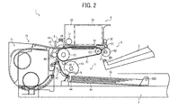
- FIG. 2 is a schematic vertical cross-sectional view illustrating an example of a configuration of the mechanical portion of the image forming apparatus 1.
- FIG. 3 is a schematic plan view illustrating the configuration of the mechanical portion of the image forming apparatus 1.
- the mechanical portion of the image forming apparatus 1 includes an image forming part 6 including a carriage 33 and so forth, a sheet feeder 7 including the sheet feed cassette 2 and so forth, a conveyance unit 8 including a conveyance belt 51 and so forth, and a discharge unit 9 including a discharge roller 62, the discharge tray 3, and so forth.
- a main guide rod 31 and a sub-guide rod 32 are extended across left and right main lateral plate 37A and 37B of the image forming apparatus 1.
- the carriage 33 is slidably supported by the main and sub-guide rods 31 and 32.
- the carriage 33 is reciprocally movable back and forth in a main scanning direction by a main scanning motor, not shown, via a timing belt to which the carriage 33 is fixed.
- Recording heads 34a and 34b (hereinafter collectively referred to as recording heads 34) each constituted of a liquid ejection head that ejects ink droplets of a specific color, that is, yellow (Y), cyan (C), magenta (M), or black (K), is mounted on the carriage 33.
- Nozzle arrays each constituted of multiple nozzles are provided to a nozzle face of each of the recording heads 34 and arrayed in a sub-scanning direction perpendicular to the main scanning direction, such that the recording heads 34 eject ink droplets of the specified colors vertically downward.
- Each of the recording heads 34a and 34b has two nozzle arrays.
- Black ink droplets (K) are ejected from a first nozzle array formed in the recording head 34a, and cyan ink droplets (C) are ejected from a second nozzle array formed therein.
- cyan ink droplets (C) are ejected from a second nozzle array formed therein.
- magenta ink droplets (M) are ejected from a first nozzle array formed in the recording head 34b, and yellow ink droplets (Y) are ejected from a second nozzle array formed therein.
- Sub-tanks 35a and 35b (hereinafter collectively referred to as sub-tanks 35) each supplying ink of the specified color to the recording head 34a or 34b are mounted on the carriage 33.
- the ink is supplied from the ink cartridges 10 detachably attachable to the cartridge loading unit 4 to the sub-tanks 35 of the recording heads 34 through supply tubes 36 by a supply pump unit 38.
- the sheet feed cassette 2 includes a platform member, which, in the present illustrative embodiment, is a bottom plate 41 on which sheets 42 is placed.
- the bottom plate 41 is hinged between a sheet feed position in which the sheet 42 placed on the bottom plate 41 is contacted by a sheet feed roller 43 provided to the image forming apparatus 1 and a lower position to which the bottom plate 41 is lowered from the sheet feed position.
- the bottom plate 41 of the sheet feed cassette 2 is located at the sheet feed position in FIG. 2 .
- the sheet feed roller 43 and a separation pad 44 disposed opposite the sheet feed roller 43 separate the sheets 42 placed on the bottom plate 41 of the sheet feed cassette 2 to feed the sheets 42 one by one from the sheet feed cassette 2 to the recording heads 34.
- the separation pad 44 is pressed against the sheet feed roller 43 by a biasing member such as a spring, not shown, and is formed of a material having a larger frictional factor against the sheet 42 than the sheet feed roller 43.
- the sheet feed roller 43 and the separation pad 44 together constitute a sheet feed unit that feeds the sheet 42 placed on the bottom plate 41 of the sheet feed cassette 2.
- the conveyance unit 8 conveys the sheet 42 fed from the sheet feed cassette 2 to the recording heads 34.
- the conveyance unit 8 includes a guide member 45 that guides the sheet 42, a counter roller 46, a conveyance guide member 47, a pressing member 48 having a pressing roller 49, and the conveyance belt 51 that electrostatically attracts the sheet 42 to convey the sheet 42 to the recording heads 34.
- the conveyance belt 51 is formed of an endless belt and is wound around a conveyance roller 52 and a tension roller 53 to be rotated in the sub-scanning direction.
- a charging roller 56 contacts a top layer of the conveyance belt 51 and is rotated by the rotation of the conveyance belt 51 to charge the conveyance belt 51.
- the conveyance roller 52 is rotatively driven by a sub-scanning motor, not shown, via a timing belt to rotate the conveyance belt 51 in the sub-scanning direction, that is, a direction of conveyance of the sheet 42.
- the discharge unit 9 discharges the sheet 42 having the image thereon formed by the recording heads 34 from the image forming apparatus 1.
- the discharge unit 9 includes a separation pick 61 that separates the sheet 42 from the conveyance belt 51, the discharge roller 62, a spur 63, and the discharge tray 3 disposed below the discharge roller 62.
- a duplex unit 71 is detachably attachable to a rear surface of the image forming apparatus 1.
- the duplex unit 71 reverses the sheet 42 conveyed by reverse rotation of the conveyance belt 51 to convey the sheet 42 between the counter roller 46 and the conveyance belt 51 again.
- An upper surface of the duplex unit 71 serves as a manual sheet feed tray 72.
- a maintenance/recovery mechanism 81 that maintains the nozzles in the recording heads 34 is provided outside the imaging range of the recording heads 34 at one end of the main scanning direction of the carriage 33 to prevent irregular ejection of the ink droplets from the nozzles of the recording heads 34.
- the maintenance/recovery mechanism 81 is constructed of cap members 82a and 82b (hereinafter collectively referred to as cap members 82), each of which covers the nozzle face of the recording head 34a or 34b, a wiper blade 83 that wipes off the nozzle face, a receiver 84 that receives ink droplets which are not used for image formation and are ejected from the nozzles to remove coagulated ink from the nozzles, and a carriage lock 87 that locks the carriage 33.
- a non-replaceable first waste tank 85 that stores waste ink discharged from the ink receiver 84 is disposed below the maintenance/recovery mechanism 81.
- a second waste tank 86 replaceable from the front side of the image forming apparatus 1 is disposed on the lateral side of the maintenance/recovery mechanism 81 below the cartridge loading unit 4. Both the ink cartridges 10 and the second waste tank 86 are replaceable from the front side of the image forming apparatus 1 by opening a front cover of the image forming apparatus 1, thereby achieving low maintenance costs.
- the image forming apparatus 1 further includes an ink receiver 88 that receives ink droplets that are not used for image formation and are ejected from the recording heads 34 to remove coagulated ink from the nozzles of the recording heads 34 during image formation.
- the ink receiver 88 is disposed outside the imaging range of the recording heads 34 at the other end of the main scanning direction of the carriage 33 and includes an opening 89 formed along a direction in which the nozzle arrays extend.
- the sheet 42 fed from the sheet feed cassette 2 one by one is guided vertically upward by the guide member 45 and is conveyed by the conveyance belt 51 and the counter roller 46.
- the leading edge of the sheet 42 is further guided by the conveyance guide member 47 and is pressed against the conveyance belt 51 by the pressing roller 49 so that the direction of conveyance of the sheet 42 is changed substantially at 90°.
- positive and negative voltages are applied alternately to the charging roller 56, that is, an alternating voltage is applied to the charging roller 56, from a voltage applicator, not shown, so that the conveyance belt 51 is charged in a pattern of an alternate charging voltages, that is, the conveyance belt 51 is alternately charged by positive and negative voltages with a predetermined width, in the direction of rotation of the conveyance belt 51 or the sub-scanning direction. Accordingly, the sheet 42 conveyed to the conveyance belt 51 thus alternately charged with the positive and negative voltages is electrostatically attracted to the conveyance belt 51 and is further conveyed in the sub-scanning direction by the rotation of the conveyance belt 51.
- the recording heads 34 are driven based on image signals while the carriage 33 is moved so that ink droplets are ejected from the recording heads 34 onto the sheet 42, which remains stationary, so as to form a single line of an image to be formed on the sheet 42. Thereafter, the sheet 42 is conveyed by a predetermined amount to perform image formation of the next line.
- the image forming apparatus 1 completes image formation and discharges the sheet 42 to the discharge tray 3.
- the carriage 33 is moved to a home position to face the maintenance/recovery mechanism 81 during maintenance of the nozzles in the recording head 34.
- the nozzle faces of the recording heads 34 are capped with the cap members 82 so that coagulated ink is sucked out from the nozzles and ink droplets not used for image formation are discharged from the nozzles so as to maintain the nozzles, thereby providing stable ejection of ink droplets from the recording heads 34 and achieving higher-quality image formation.
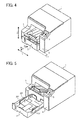
- FIG. 4 is a perspective view illustrating the external appearance of the image forming apparatus 1 from which the sheet feed cassette 2 is withdrawn forward a predetermined distance, such that the bottom plate 41 is located at the lower position.
- FIG. 5 is a perspective view illustrating the external appearance of the image forming apparatus 1 in a state in which the sheet feed cassette 2 is withdrawn to a sheet supply position.
- arrow Xa indicates an insertion direction in which the sheet feed cassette 2 is inserted into the image forming apparatus 1
- arrow Xb indicates a withdrawal direction in which the sheet feed cassette 2 is withdrawn from the image forming apparatus 1
- arrow Y indicates a width direction of the image forming apparatus 1 perpendicular to the insertion direction Xa and the withdrawal direction Xb
- arrow Z indicate a vertical direction.
- the withdrawal direction Xb corresponds to a direction of discharge of the sheet 42 to the discharge tray 3
- the width direction Y corresponds the width direction of the sheet 42 and the main scanning direction.
- the bottom plate 41 of the sheet feed cassette 2 is lowered to the lower position so that the discharge tray 3 can swing open from the sheet feed cassette 2 to an open position so as to open the sheet feed cassette 2 as illustrated in FIG. 7 described in detail later.
- the discharge tray 3 swings downward to a closed position to close the sheet feed cassette 2 as illustrated in FIG. 4 , the sheet feed cassette 2 can be inserted into the image forming apparatus 1.
- reference numeral 207 in FIG. 5 denotes a side fence that aligns the sheets 42 placed on the bottom plate 41 in the width direction of the sheets 42.
- the discharge tray 3 swings downward to the closed position to close the sheet feed cassette 2 so that the sheet feed cassette 2 can be inserted into the image forming apparatus 1.
- the discharge tray 3 swings open from the sheet feed cassette 2 as illustrated in FIG. 5 , the sheet feed cassette 2 cannot be inserted into the image forming apparatus 1. In other words, the discharge tray 3 must be located at the closed position in order to set the sheet feed cassette 2 in the image forming apparatus 1.
- the image forming apparatus 1 has a front-loading configuration in which the sheet feed cassette 2 is withdrawn from the image forming apparatus 1 to supply the sheets 42 to the sheet feed cassette 2 and thereafter the sheet feed cassette 2 is inserted into the image forming apparatus 1.
- the above-described configuration allows easy supply of the sheets 42 to the sheet feed cassette 2 from the front side of the image forming apparatus 1 and reduces installation space on both lateral sides of the image forming apparatus 1.
- FIG. 6 is a vertical cross-sectional view illustrating an example of a configuration of the sheet feed cassette 2 set in the image forming apparatus 1.
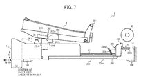
- FIG. 7 is vertical cross-sectional view illustrating an example of a configuration of the sheet feed cassette 2 withdrawn from the image forming apparatus 1 by a certain distance.
- a leading edge of the bottom plate 41 is a free edge hinged around a support shaft 202 provided inside the sheet feed cassette 2.
- the leading edge of the bottom plate 41 is supported by a trailing end 203a of a link member 203 via a spring 204.
- the link member 203 is hinged about a support shaft 205 provided to a main body 201 of the sheet feed cassette 2.
- the leading end 203b of the link member 203 is separated from the contact portion 11 of the image forming apparatus 1 and is rotated in a direction indicated by arrow C by both the biasing force of the spring 204 and the weight of the bottom plate 41 and the sheets 42, not shown in FIG. 7 , placed on the bottom plate 41. Accordingly, the trailing end 203a of the link member 203 is lowered, thus lowering the bottom plate 41 to the lower position.
- the bottom plate 41 located at the lower position contacts a protrusion 206 provided to a front bottom end of the main body 201 of the sheet feed cassette 2.
- a user can hear a noise when the bottom plate 41 is lowered to contact the protrusion 206 and confirm that the bottom plate 41 is located at the lower position.
- the discharge tray 3 also functions as a cover that covers the sheet feed cassette 2.
- the discharge tray 3 is hinged about a support shaft 301 provided to the image forming apparatus 1 to open and close the sheet feed cassette 2.
- the sheet feed cassette 2 is slidable against a base portion 100 fixed to the bottom of the image forming apparatus 1 in both the insertion direction Xa and the withdrawal direction Xb by the weight of the sheet feed cassette 2 itself.
- a well-known inexpensive configuration is used for positioning the sheet feed cassette 2 in the vertical direction Z.
- the lock mechanism 13 that locks the discharge tray 3 is provided to both the sheet feed cassette 2 and the discharge tray 3.
- the lock mechanism 13 is constructed of a locked member, which, in the present illustrative embodiment, is a tray lock member 311 provided to the discharge tray 3, and a locking member, which, in the present illustrative embodiment, is a cassette hook member 211 provided to the sheet feed cassette 2 to engage the tray lock member 311.
- the lock mechanism 13 is provided on both lateral sides of the sheet feed cassette 2 in the width direction Y.
- the tray lock member 311 may be formed together with the discharge tray 3 as a single integrated unit or may be provided individually from the discharge tray 3 as a separate member.
- the cassette hook member 211 may be formed together with the sheet feed cassette 2 as a single integrated unit or may be provided individually from the sheet feed cassette 2 as a separate member.
- the lock mechanism 13 is disposed inside the sheet feed cassette 2 in the width direction Y and has a slightly different shape.
- the tray lock member 311 is extended substantially in the horizontal direction to engage the cassette hook member 211 in the substantially horizontal direction.
- substantially horizontal direction refers to both the horizontal direction and a direction within design tolerance relative to the horizontal direction.
- the cassette hook member 211 engages the tray lock member 311 as illustrated in FIG. 6 .
- the cassette hook member 211 is disengaged from the tray lock member 311 when the sheet feed cassette 2 is withdrawn from the image forming apparatus 1 by the distance L1 or greater as illustrated in FIG. 7 .
- the discharge tray is swung upward from the sheet feed cassette even when the sheet feed cassette is not withdrawn from the image forming apparatus by the predetermined distance. Consequently, the user may supply the sheets to the sheet feed cassette from a slight gap formed between the sheet feed cassette and the discharge tray by slightly withdrawing the sheet feed cassette from the image forming apparatus. As a result, because the bottom plate of the sheet feed cassette is not located at the lower position in such a state, the sheets may be inserted beyond a nip portion between the sheet feed roller and the separation pad, thereby possibly causing multiple feeding of the sheets.
- the lock mechanism 13 is provided such that the discharge tray 3 is not swung unless the sheet feed cassette 2 is withdrawn from the image forming apparatus 1 by the distance L1 to lower the bottom plate 41 of the sheet feed cassette 2 to the lower position.
- the discharge tray 3 is not swung in a state in which the sheet feed cassette 2 is set in the image forming apparatus 1 so that the sheets 42 cannot be supplied to the sheet feed cassette 2 from the slight gap between the sheet feed cassette 2 and the discharge tray 3, thereby preventing insertion of the sheets 42 beyond a nip portion N between the sheet feed roller 43 and the separation pad 44 and thus preventing multiple feeding of the sheets 42.
- the image forming apparatus 1 includes the restriction unit such that the discharge tray 3 is swung only when the bottom plate 41 of the sheet feed cassette 2 is located at the lower position, and is not swung when the bottom plate 41 is located at the sheet feed position above the lower position.
- the discharge tray 3 is not swung unless the bottom plate 41 of the sheet feed cassette 2 is located at the lower position, thereby achieving proper supply of the sheets 42 to the sheet feed cassette 2 and proper feeding of the sheets 42 from the sheet feed cassette 2.
- FIGS. 8A and 8B are vertical cross-sectional views respectively illustrating an example of a configuration of a related-art stopper mechanism 230.
- FIGS. 8C and 8D are vertical cross-sectional views along a line A-A in FIG. 6 , respectively illustrating an example of a configuration of a stopper mechanism 230A provided to the image forming apparatus according to the first illustrative embodiment.
- FIGS. 9A, 9B, and 9C are partial vertical cross-sectional views respectively illustrating transitional states of the stopper mechanism 230A and the lock mechanism 13 during insertion of the sheet feed cassette 2 into the image forming apparatus 1 according to the first illustrative embodiment.
- FIG. 10 is a partial perspective view illustrating the stopper mechanism 230A and the lock mechanism 13 when the sheet feed cassette 2 is withdrawn from the image forming apparatus 1 according to the first illustrative embodiment.
- the related-art stopper mechanism 230 is described in detail with reference to FIGS. 8A and 8B .
- the related-art stopper mechanism 230 is basically the same as the technique described previously in the background section of this specification, and includes a stopped member 231 movably mounted to the sheet feed cassette 2.
- the stopped member 231 is movable in the vertical direction and includes a main body 231a, a sloped portion 232 pressed by the discharge tray 3 disposed above the main body 231a, and a protrusion 233 formed together with the main body 231a to restrict insertion of the sheet feed cassette 2 into the image forming apparatus 1.
- the stopped member 231 is biased upward by a spring, not shown, provided within a hollow portion of the main body 231a, and engagement of an engagement portion, not shown, provided to a bottom end of the stopped member 231 and an engaged portion, not shown, restricts an amount of upward protrusion of the stopped member 231.
- the protrusion 233 of the stopped member 231 contacts a stopper member 241 fixed to the image forming apparatus 1 when the stopped member 231 is lifted to an upper position.
- the stopper mechanism 230 is provided on both lateral sides of the sheet feed cassette 2 in the width direction Y.
- the stopper mechanism 230 when the discharge tray 3 swings open from the sheet feed cassette 2, the stopped member 231 of the sheet feed cassette 2 is lifted by a biasing force of the spring so that the protrusion 233 of the stopped member 231 mounted to the sheet feed cassette 2 contacts the stopper member 241 fixed to the image forming apparatus 1 as illustrated in FIG. 8A . As a result, the sheet feed cassette 2 cannot be inserted into the image forming apparatus 1.
- the stopper mechanism 230 of the related art restricts insertion of the sheet feed cassette 2 into the image forming apparatus 1 when the discharge tray 3 is located at the open position, thereby preventing insertion of the sheet feed cassette 2 into the image forming apparatus 1 when the discharge tray 3 is not located at the closed position.
- the protrusion 233 of the stopped member 231 protrudes outward from the sheet feed cassette 2 in the width direction Y.
- the stopper member 241 provided to the image forming apparatus 1 and opposite the protrusion 233 of the stopped member 231 protrudes toward the sheet feed cassette 2. Because recessed portions need to be formed in all the parts along a path of insertion and withdrawal of the sheet feed cassette 2 in a case in which neither the stopped member 231 nor the stopper member 241 has the protrusion, it is required to form the protrusions in both the stopped member 231 and the stopper member 241.
- a gap of from 5 mm to 10 mm is necessary between the image forming apparatus 1 and both left and right sides of the sheet feed cassette 2 in the width direction Y.
- a gap ⁇ T of from 5 mm to 10 mm is required between the sheet feed cassette 2 and the image forming apparatus 1 as shown in FIG. 8A , causing an increase in the width of the image forming apparatus 1 by from 10 mm to 20 mm.
- the image forming apparatus 1 according to the first illustrative embodiment is compact and is often installed in a small space near the user, even a slight increase in the size of the image forming apparatus 1 may prevent installation of the image forming apparatus 1 in such a small space.
- the stopper mechanism 230A that restricts insertion of the sheet feed cassette 2 into the image forming apparatus 1 when the discharge tray 3 swings open from the sheet feed cassette 2 to prevent improper supply of the sheets 42 to the sheet feed cassette 2 is provided to the image forming apparatus 1 without resulting in an increase in the size of the image forming apparatus 1.
- the function of the protrusion 233 of the related art is provided to a different portion of the stopped member 231 as described in detail below.
- a gap ⁇ T' between the sheet feed cassette 2 and the image forming apparatus 1 can be minimized within a range between 0.5 mm and 1 mm, which is smaller than the gap ⁇ T.
- stopper mechanism 230A provided to the image forming apparatus 1 according to the first illustrative embodiment, with reference to FIGS. 8C, 8D , 9A, 9B , 9C , and 10 .
- the stopper mechanism 230A includes a stopped member 231A and a stopper member 241A, respectively.
- the stopped member 231A is disposed inside the sheet feed cassette 2 in the width direction Y and constructed of a switching surface, which, in the present illustrative embodiment, is a guide surface 238, and a stopped surface, which, in the present illustrative embodiment, is a contact surface 239 adjacent to the guide surface 238.
- the stopper member 241A is provided to the image forming apparatus 1 to engage the stopped member 231A inside the sheet feed cassette 2 in the width direction Y.
- the stopped member 231A is movably mounted to the sheet feed cassette 2 in the vertical direction Z and is lifted from the sheet feed cassette 2 toward the discharge tray 3 when the discharge tray 3 swings open from the sheet feed cassette 2.
- the stopped member 231A is constructed of a main body 231Aa, the sloped portion 232 pressed by the bottom wall 3 a of the discharge tray 3 disposed above the main body 231Aa, the contact surface 239 contacted by the stopper member 241A when the stopped member 231A is lifted to the upper position, the guide surface 238 provided adjacent to the contact surface 239 along the insertion direction Xa to move the stopped member 231A in the vertical direction by engagement with the stopper member 241A, and a hollow portion within which the spring 234 is disposed.
- the guide surface 238 is sloped downward from upstream to downstream in the insertion direction Xa of the sheet feed cassette 2.
- the sloped portion 232, the contact surface 239, the guide surface 238, and the hollow portion together form the stopped member 231A as a single integrated unit in this case made of resin.
- the stopped member 231A is supported via the spring 234 by a support member 237 fixed to the sheet feed cassette 2.
- the stopped member 231A is biased upward by the spring 234 provided within the hollow portion of the main body 231Aa, and engagement of an engagement portion 235 provided to the bottom end of the stopped member 231A and an engaged portion 236 fixed to the sheet feed cassette 2 restricts an amount of upward protrusion of the stopped member 231A.
- the stopper mechanism 230A is provided to both sides of the sheet feed cassette 2 in the width direction Y.
- a recessed portion 302 which prevents contact with the stopper member 241A fixed to the image forming apparatus 1 is formed in the bottom of both external walls of the discharge tray 3 in the width direction Y.
- the recessed portion 302 is recessed inward in the discharge tray 3 in the width direction Y.
- the stopped member 231A of the sheet feed cassette 2 is lifted by the biasing force of the spring 234 when the discharge tray 3 swings open from the sheet feed cassette 2 so that the contact surface 239 contacts the stopper member 241A of the image forming apparatus 1 to prevent the sheet feed cassette 2 from being inserted into the image forming apparatus 1 in the insertion direction Xa.
- the sloped guide surface 238 that contacts and engages the stopper member 241A divides the force to insert the sheet feed cassette 2 in the insertion direction Xa into a component of force that moves the stopped member 231A further downward against the biasing force of the spring 234 so that the stopped member 231A is lowered to the lower position as illustrated in FIG. 9C . Accordingly, the sheet feed cassette 2 can be inserted into the image forming apparatus 1 without interference from the stopper member 241A.
- the cassette hook member 211 engages the tray lock member 311 to lock the discharge tray 3 toward the sheet feed cassette 2.
- operation of the stopper mechanism 230A during withdrawal of the sheet feed cassette 2 from the image forming apparatus 1 in the withdrawal direction Xb is the reverse of the above-described steps.
- installation space of the stopper mechanism 230A in the width direction Y of the image forming apparatus 1 can be minimized, and thus making the image forming apparatus 1 more compact while achieving the effects achieved by the related art.
- the stopper mechanism 230A may be disposed only on the single side of the sheet feed cassette 2 in the width direction Y. As a result, the number of components can be further reduced and the image forming apparatus 1 can be further downsized, thereby reducing production costs.
- the shape and position of the discharge tray 3 and the stopper mechanism 230A are not limited to the above-described example.
- the bottom wall 3a of the discharge tray 3 may be formed to contact the sloped portion 232 of the stopped member 231A when the discharge tray 3 is located at the closed position.
- the first variation of the first illustrative embodiment provides a configuration that reduces the size of the engagement space for the tray lock member 311 of the discharge tray 3 as described in detail below.
- the wide engagement space is required for the tray lock member 311 of the discharge tray 3 because of the following reasons: neither the discharge tray 3 nor the sheet feed cassette 2 is fixed to the image forming apparatus 1 and has a positioning configuration, and therefore, both the discharge tray 3 and the sheet feed cassette 2 are attached to the image forming apparatus 1 with play; and provision of a slippage prevention member to the sheet feed cassette 2 and the discharge tray 3 prevents easy insertion of the sheet feed cassette 2 into the image forming apparatus 1.
- a stopper member 241B having a locking member which, in the first variation, is a lock pawl 2412, is provided to the image forming apparatus 1.
- the lock pawl 2412 is movable in conjunction with insertion and withdrawal of the sheet feed cassette 2 into and from the image forming apparatus 1.
- FIG. 11A is a schematic view illustrating an example of a configuration of the lock pawl 2412 provided to the stopper member 241B according to the first variation in a state in which the lock pawl 2412 is disengaged from the tray lock member 311.
- FIG. 11B is a schematic view illustrating the configuration of the lock pawl 2412 in a state in which the lock pawl 2412 engages the tray lock member 311.
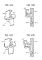
- FIG. 12A is a perspective view illustrating the configuration of the lock pawl 2412 in the state in which the lock pawl 2412 engages the tray lock member 311.
- FIG. 12B is an enlarged schematic view of the lock pawl 2412 illustrated in FIG. 12A.
- FIG. 12C is a perspective view illustrating the configuration of the lock pawl 2412 in the state in which the lock pawl 2412 is disengaged from the tray lock member 311.
- FIG. 12D is an enlarged schematic view of the lock pawl 2412 illustrated in FIG. 12C .
- FIG. 13 is a perspective view illustrating an example of a configuration of the tray lock member 311 provided to the discharge tray 3 according to the first variation of the first illustrative embodiment.
- the cassette hook member 211 of the sheet feed cassette 2 is eliminated, and the stopper member 241B is provided to the image forming apparatus 1 in place of the stopper member 241A.
- the rest of the configuration according to the first variation is the same as the configuration according to the first illustrative embodiment.
- the stopper member 241B includes the lock member, which, in the first variation, is the lock pawl 2412 movably provided to a stopper 2411 disposed to the image forming apparatus 1.
- the lock pawl 2412 engages the stopped member 231A to lock the discharge tray 3.
- the lock pawl 2412 has a shape folded several times substantially at 90° and includes a columnar portion 2412a formed together with the lock pawl 2412 at a base edge thereof.
- the lock pawl 2412 is supported by a bearing 2411 a of the stopper 2411 and hinged around the columnar portion 2412a.
- a notch 2411b that accommodates the lock pawl 2412 when the lock pawl 2412 swings in a clockwise direction in FIGS. 12A to 12D is formed in the stopper 2411.
- the lock pawl 2412 swings downward by its own weight as illustrated in FIG. 11A , 12C, or 12D . At this time, a portion of the lock pawl 2412 protrudes beyond the surface of the stopper member 231A that contacts the lock pawl 2412 upon engagement.
- the lock pawl 2412 Operation of the lock pawl 2412 is described in detail below.
- the stopped member 231A When the discharge tray 3 is pressed downward to the closed position and the sheet feed cassette 2 is inserted into the image forming apparatus 1, the stopped member 231A is moved downward to prevent contact against the stopper 2411 as illustrated in FIG. 11B , 12A, or 12B .
- the stopped member 231A presses a bottom portion 2412b of the lock pawl 2412 upward against the weight of the lock pawl 2412 so that the lock pawl 2412 engages the tray lock member 311 of the discharge tray 3. Accordingly, the discharge tray 3 is locked while being closed relative to the sheet feed cassette 2 as illustrated in FIG. 13 .
- the large space required for engagement of the tray lock member 311 of the discharge tray 3 and the cassette hook member 211 of the sheet feed cassette 2 according to the first illustrative embodiment is not needed in the configuration according to the first variation.
- reduction in the size of the space required for engagement of the lock member and the tray lock member 311 can be achieved in the first variation, thereby making the image forming apparatus 1 more compact.
- FIG. 14 is a perspective view illustrating an example of a configuration of a stopped member 231B provided to the sheet feed cassette 2 according to the second variation of the first illustrative embodiment.
- the stopped member 231B formed of metal is used in a stopper mechanism 230B provided to the image forming apparatus 1 according to the second variation.
- the rest of the configuration according to the second variation is the same as the configuration according to the first variation.
- the stopped member 231B be formed of metal such as a thin steel plate.
- a right base end of the stopped member 231B in FIG. 14 is supported by an external wall of the sheet feed cassette 2 via a support shaft 250. Accordingly, a left end of the stopped member 231B, which is a free end, is hinged in the vertical direction Z.
- the contact surface 239, the guide surface 238, and the sloped portion 232 are continuously formed in the free end of the stopped member 231B, and the free end of the stopped member 231B engages the stopper member 241B provided to the image forming apparatus 1 at a portion inside the sheet feed cassette 2 in the width direction Y.
- the free end of the stopped member 231B is biased upward by a coil spring, not shown, attached to the support shaft 250.
- the stopped member 231B is supported by the external wall of the sheet feed cassette 2 to be movable in the vertical direction Z for ease of explanation of reduction in the gap between the stopped member 231B and the stopper member 241B in the above example, it is preferable that the stopped member 231B be disposed inside the sheet feed cassette 2 in the width direction Y to be movable in the vertical direction Z.
- the stopped member 231B according to the second variation can achieve the same effects achieved by the stopped member 231A according to first illustrative embodiment and the first variation.
- the space for the stopped member 231B provided to the sheet feed cassette 2 can be minimized in the second variation. Combination of the configurations according to the first and second variations can make the image forming apparatus 1 more compact while achieving the effects achieved by the prior art.
- a recording medium fed from the sheet feed cassette from the front portion to the rear portion of the image forming apparatus is generally reversed to be conveyed to the recording head.
- the recording medium having the image thereon is discharged to the discharge tray disposed above the sheet feed cassette.
- the discharge tray is hinged to open or close the sheet feed cassette.
- the sheet feed cassette in order to achieve smooth attachment of the sheet feed cassette to the image forming apparatus, the sheet feed cassette must be inserted horizontally into the image forming apparatus so as not to contact the discharge tray disposed above the sheet feed tray upon insertion of the sheet feed cassette.
- provision of the restriction member is required such that movement of the discharge tray is restricted when the sheet feed cassette is set in the image forming apparatus.
- the restriction unit that is, the lock mechanism 13 that locks the discharge tray 3
- the lock mechanism 13 is constructed of the tray lock member 311 provided to the discharge tray 3 and the cassette hook member 211 provided to the sheet feed cassette 2 to engage the tray lock member 311.
- the tray lock member 311 is extended substantially in the horizontal direction to engage the cassette hook member 211 substantially in the horizontal direction.
- the cassette hook member 211 engages the tray lock member 311 as illustrated in FIG. 6 .
- the cassette hook member 211 is disengaged from the tray lock member 311 when the sheet feed cassette 2 is withdrawn from the image forming apparatus 1 by the distance L1 or greater as illustrated in FIG. 7 .
- the cassette hook member 211 contacts the front surface of the discharge tray 3, thereby preventing smooth insertion of the sheet feed cassette 2 into the image forming apparatus 1. Provision of a sloped portion to a contact part in which the tray lock member 311 and the cassette hook member 211 contact each other cannot completely solve the above problem. In addition, provision of a large clearance between the cassette hook member 211 of the sheet feed cassette 2 and the front surface of the discharge tray 3 for the purpose of solving the above problem may increase the size of the image forming apparatus 1.
- both the discharge tray 3 and the sheet feed cassette 2 are lifted together to combine the sheet feed cassette 2 with the discharge tray 3, and then the sheet feed cassette 2 thus combined with the discharge tray 3 is inserted into the image forming apparatus 1 according to the second illustrative embodiment as described in detail below.
- FIGS. 15A and 15B are vertical cross-sectional views respectively illustrating transitional states of an insertion mechanism 25 provided to the image forming apparatus 1 according to the second illustrative embodiment during insertion of the sheet feed cassette 2 into the image forming apparatus 1.
- FIGS. 16A and 16B are vertical cross-sectional views respectively illustrating transitional states of the insertion mechanism 25 after the state illustrated in FIG. 15B .
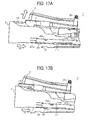
- FIGS. 17A and 17B are vertical cross-sectional views respectively illustrating operation of inserting the sheet feed cassette 2 into the image forming apparatus 1 using the insertion mechanism 25.
- a lock mechanism 103 is used as the restriction unit in the second illustrative embodiment.
- the sheet feed cassette 2 and the discharge tray 3 are substantially combined together in the vertical direction Z by the lock mechanism 103.
- the insertion mechanism 25 is used in the second illustrative embodiment such that the sheet feed cassette 2 thus combined with the discharge tray 3 is inserted into the image forming apparatus 1 while an upstream portion of the sheet feed cassette 2 in the insertion direction Xa is lifted.
- a rail 114 having a recessed portion 114a is provided to the base portion 100 of the image forming apparatus 1, and a reference protrusion 252 that engages the rail 114 is provided to the bottom portion of the sheet feed cassette 2.
- the rest of the configuration according to the second illustrative embodiment is the same as the configuration according to the first illustrative embodiment.
- the lock mechanism 103 is constructed of a locked member, which, in the present illustrative embodiment, is a lock receiver 111 provided to the discharge tray 3, and a locking member, which, in the present illustrative embodiment, is a lock member 110 provided to the sheet feed cassette 2 to engage the lock receiver 111.
- the lock member 110 has a sloped surface sloping downward from downstream to upstream in the insertion direction Xa of the sheet feed cassette 2.
- the lock mechanism 103 is provided to both sides of the sheet feed cassette 2 in the width direction Y.
- the sheet feed cassette 2 has a bottom wall 201a slidable against the base portion 100 of the image forming apparatus 1.
- a wide recessed portion 201b facing downward is formed at the center of the bottom wall 201a along the insertion direction Xa.
- the insertion mechanism 25 is constructed of a sloped guide portion, which, in the present illustrative embodiment, is a base plate 107 provided to the base portion 100 of the image forming apparatus 1, and a first protrusion, which, in the present illustrative embodiment, is a protrusion 251 formed in the bottom wall 201a of the sheet feed cassette 2.
- the base plate 107 is constructed of a sloped surface sloping upward from upstream to downstream in the insertion direction Xa and a stepped portion 107a.
- the protrusion 251 protrudes downward and engages the base plate 107.
- the rail 114 having the recessed portion 114a is provided to the base portion 100 of the image forming apparatus 1.
- a second protrusion which, in the present illustrative embodiment, is the reference protrusion 252 protruding downward to engage the receiver rail 114 is provided to the recessed portion 201b of the sheet feed cassette 2.
- the protrusion 251 provided to the sheet feed cassette 2 gently passes over the sloped surface of the base plate 107 provided to the base portion 100 of the image forming apparatus 1 so that the front side of the sheet feed cassette 2, that is, the left end of the sheet feed cassette 2 in FIGS. 15A and 15B , is lifted as indicated by bold arrow Xa in FIG. 15B .
- the lock member 110 having the sloped surface contacts a front bottom portion 3b of the discharge tray 3. Accordingly, the front side of the discharge tray 3 is also smoothly lifted as illustrated in FIG. 16A as the front side of the sheet feed cassette 2 is lifted.
- the lock member 110 of the sheet feed cassette 2 engages the lock receiver 111 of the discharge tray 3. Accordingly, while being located at the closed position, the discharge tray 3 is substantially combined with the sheet feed cassette 2 in the vertical direction Z, and the sheet feed cassette 2 thus combined with the discharge tray 3 is inserted into the image forming apparatus 1 in the insertion direction Xa.
- the front side of the sheet feed cassette 2 is lifted in a direction indicated by bold arrow Xd before the reference protrusion 252, that positions the sheet feed cassette 2 upon insertion of the sheet feed cassette 2 into the image forming apparatus 1, contacts a left edge of the rail 114 in order to prevent the reference protrusion 252 from contacting the left edge of the rail 114.
- the sheet feed cassette 2 can be smoothly inserted into the image forming apparatus 1 and thus preventing abrasion of the reference protrusion 252 even in a case of repeated insertion of the sheet feed cassette 2 into the image forming apparatus 1.
- the lock member 110 and the lock receiver 111 engage each other as the sheet feed cassette 2 is slanted and thus lifting the front side of the discharge tray 3. Accordingly, the sheet feed cassette 2 can be smoothly inserted into the image forming apparatus 1 while swinging movement of the discharge tray 3 is still restricted with an uncomplicated configuration.
- the insertion mechanism 25 is used in the second illustrative embodiment so that the sheet feed cassette 2 is lifted together with the discharge tray 3 to be combined with the discharge tray 3 upon insertion of the sheet feed cassette 2 into the image forming apparatus 1.
- the sheet feed cassette 2 can be smoothly inserted into the image forming apparatus 1 at a wide range of angle while improper supply of the sheets can be still prevented with the uncomplicated configuration.
- the rail 114 having the recessed portion 114a is provided to the base portion 100 of the image forming apparatus 100, and the reference protrusion 252 protruding downward to engage the rail 114 is provided to the bottom wall 201a of the sheet feed cassette 2.
- the front side of the sheet feed cassette 2 is lifted in the direction indicated by the bold arrow Xd before the reference protrusion 252 contacts the left edge of the rail 114 in order to prevent the reference protrusion 252 from contacting the left edge of the receiver rail 114 upon insertion of the sheet feed cassette 2 into the image forming apparatus 1.
- the sheet feed cassette 2 can be further smoothly inserted into the image forming apparatus 1, and thus preventing abrasion of the reference protrusion 252 and extending the product life of the sheet feed cassette 2 even in a case of repeated insertion of the sheet feed cassette 2 into the image forming apparatus 1.
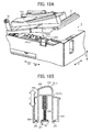
- FIG. 18A is a perspective view illustrating an example of a configuration of the stopper mechanism 230C provided to the image forming apparatus 1 according to the second illustrative embodiment.
- FIG. 18B is an enlarged vertical cross-sectional view illustrating an example of a configuration of a stopped member 231C included in the stopper mechanism 230C.
- FIG. 19A is a vertical cross-sectional view illustrating operation of the stopper mechanism 230C in a state in which the discharge tray 3 swings open from the sheet feed cassette 2.
- FIG. 19B is a vertical cross-sectional view illustrating operation of the stopper mechanism 230C in a state in which the discharge tray 3 is located at the closed position.
- FIG. 19A is a perspective view illustrating an example of a configuration of the stopper mechanism 230C provided to the image forming apparatus 1 according to the second illustrative embodiment.
- FIG. 18B is an enlarged vertical cross-sectional view illustrating an example of a configuration of a stopped member 231C included in
- FIG. 20A is a vertical cross-sectional view illustrating the stopper mechanism 230C in a state in which the sheet feed cassette 2 is set in the image forming apparatus 1.
- FIG. 20B is a horizontal cross-sectional view along a line D-D in FIG. 20A .
- the stopped member 231C and a stopper member 241C engageable with the stopped member 231C are included in the stopper mechanism 230C according to the second illustrative embodiment.
- the rest of the configuration according to the second illustrative embodiment is the same as the configuration according to the first illustrative embodiment.
- the stopped member 231C of the stopper mechanism 230C is movably mounted to the sheet feed cassette 2 in the vertical direction Z, and is lifted from the sheet feed cassette 2 toward the discharge tray 3 when the discharge tray 3 swings open from the sheet feed cassette 2 as illustrated in FIG. 18A .
- the stopped member 231C includes the sloped portion 232 pressed by the bottom wall 3a of the discharge tray 3 disposed above a main body 231Ca of the stopped member 231C, the contact surface 239 contacted by the stopper member 241C when the stopped member 231C is lifted, the guide surface 238 provided adjacent to the contact surface 239 along the insertion direction Xa to move the stopped member 231C in the vertical direction Z by engagement with the stopper member 241C, and the hollow portion within which the spring 234 is disposed.
- the guide surface 238 is sloped downward from upstream to downstream in the insertion direction Xa of the sheet feed cassette 2.
- the sloped portion 232, the contact surface 239, the guide surface 238, and the hollow portion together form the stopped member 231C as a single integrated unit with resin.
- the stopped member 231C is supported via the spring 234 by the support member 237 fixed to the sheet feed cassette 2.
- the stopped member 231C is biased upward by the spring 234 provided within the hollow portion of the main body 231Ca, and engagement of the engagement portion 235 provided to the bottom end of the stopped member 231C and the engaged portion 236 fixed to the sheet feed cassette 2 restricts an amount of upward protrusion of the stopped member 231C.
- the stopper mechanism 230C is provided inside the sheet feed cassettes 2 on both sides of the sheet feed cassette 2 in the width direction Y.
- the stopper mechanism 230C Operation of the stopper mechanism 230C is described in detail below. As illustrated in FIG. 19A , the stopped member 231C provided to the sheet feed cassette 2 is lifted by the biasing force of the spring 234 when the discharge tray 3 swings open from the sheet feed cassette 2 so that the contact surface 239 contacts the stopper member 241C provided to the image forming apparatus 1 to prevent insertion of the sheet feed cassette 2 into the image forming apparatus 1 in the insertion direction Xa.
- the stopper member 241C first contacted by the contact surface 239 is then contacted by the guide surface 238 of the stopped member 231C as the sheet feed cassette 2 is inserted into the image forming apparatus 1.
- the sloped guide surface 238 that contacts and engages the stopper member 241C divides the force to insert the sheet feed cassette 2 in the insertion direction Xa into a component of force that moves the stopped member 231C further downward against the biasing force of the spring 234 so that the sheet feed cassette 2 can be inserted into the image forming apparatus 1 without interference of the stopper member 241C.
- the bottom surface 3a of the discharge tray 3 presses the sloped portion 232 of the stopped member 231C downward to lower the stopped member 231C so that the stopped member 231C is not contacted by the stopper member 241C.
- the recessed portion 302 which prevents contact with the stopper member 241C is formed inwardly at the bottom of both external walls of the discharge tray 3 in the width direction Y, thereby contacting the bottom surface 3 a of the discharge tray 3 against the stopped member 231C. Accordingly, the sheet feed cassette 2 can be smoothly inserted into the image forming apparatus 1 without interference of the stopper member 241C.
- the bottom plate 41 Upon completion of insertion of the sheet feed cassette 2 into the image forming apparatus 1, the bottom plate 41 is located at the sheet feed position so that the sheets 42 can be fed from the sheet feed cassette 2.
- the installation space of the stopper mechanism 230C in the width direction Y of the image forming apparatus 1 can be minimized, and thus making the image forming apparatus 1 more compact.
- the stopper mechanism 230C may be disposed only on the single side of the sheet feed cassette 2 in the width direction Y. As a result, the number of components can be further reduced and the image forming apparatus 1 can be further downsized, thereby reducing production costs.
- the foregoing illustrative embodiment is also applicable to image forming apparatuses employing the electrophotographic method such as printers, copiers, plotters, facsimile machines, and multifunction devices having two or more those capabilities as long as the sheet feed cassette 2 and the discharge tray 3 according to the foregoing illustrative embodiments can be installed.
Landscapes
- Physics & Mathematics (AREA)
- General Physics & Mathematics (AREA)
- Engineering & Computer Science (AREA)
- Mechanical Engineering (AREA)
- Sheets, Magazines, And Separation Thereof (AREA)
- Electrophotography Configuration And Component (AREA)
- Paper Feeding For Electrophotography (AREA)
- Pile Receivers (AREA)
Abstract
Description
- Exemplary aspects of the present invention generally relate to an image forming apparatus such as a printer, copier, plotter, facsimile machine, or multifunction device having two or more of these capabilities.
- One type of image forming apparatus, such as a printer, copier, plotter, facsimile machine, or multifunction device having two or more of these capabilities, is an inkjet recording device employing a liquid ejection recording method. The inkjet recording device includes a recording head that ejects droplets of a recording liquid such as ink from nozzles in the recording head onto a sheet of recording media to form an image on the sheet. Examples of the inkjet recording device include a serial-type image forming apparatus, in which the recording head ejects ink droplets while moving in a main scanning direction to form an image on the sheet, and a line-type image forming apparatus equipped with a line-type recording head that ejects ink droplets while remaining stationary to form an image on the sheet.
- The image forming apparatus generally includes a sheet feed tray attached to the image forming apparatus or a sheet feed cassette detachably attachable to the image forming apparatus, from which the sheet is fed to the image forming apparatus. It is to be noted that, in this specification, the sheet feed tray is either mounted or detachably attached to the image forming apparatus and need not be detached from the image forming apparatus upon supply of sheets to the sheet feed tray, whereas the sheet feed cassette is detachably attached to the image forming apparatus and needs to be withdrawn or detached from the image forming apparatus to resupply the sheets.
- The sheet feed cassette is generally disposed near the bottom portion of the image forming apparatus. In a compact image forming apparatus, a mechanism for sheet feeding and sheet separation is often provided on the opposite side from a grip of the sheet feed cassette used for withdrawing the sheet feed cassette from the image forming apparatus upon, for example, supply of the sheets to the sheet feed cassette.
- In addition, a discharge tray to which the sheet having the image formed thereon is discharged is generally disposed above and adjacent to the sheet feed cassette in order to make the image forming apparatus more compact. The discharge tray is often hinged to allow the sheet feed cassette to be opened and closed, thereby facilitating removal of jammed or misplaced sheets. However, because the above-described configuration allows supply of the sheets without detaching the sheet feed cassette from the image forming apparatus, the sheets may be improperly supplied to the sheet feed cassette.
- For the purpose of properly supplying the sheets to the sheet feed cassette by opening a cover, that is, the discharge tray, from the sheet feed cassette, there is known a configuration that prevents the discharge tray from swinging open from the sheet feed cassette and thus preventing supply of the sheets to the sheet feed cassette unless the sheet feed cassette is withdrawn to a certain position from the image forming apparatus. In addition, a stopper mechanism that prevents insertion of the sheet feed cassette into the image forming apparatus when the discharge tray swings open from the sheet feed cassette may be used.
- However, the stopper mechanism requires a large installation space especially in a width direction of the image forming apparatus perpendicular to a direction of withdrawal of the sheet feed cassette from the image forming apparatus, thereby preventing reduction in the size of the image forming apparatus.
- In view of the foregoing, illustrative embodiments of the present invention provide a novel image forming apparatus in which recording media are properly supplied to a sheet feed cassette and an installation space for a stopper mechanism is minimized and thus making the image forming apparatus more compact.
- In one illustrative embodiment, an image forming apparatus includes a sheet container at least partially withdrawable from the image forming apparatus to a sheet supply position and including a platform member on which a sheet is placed, the platform member being hinged between a sheet feed position in which the sheet placed on the platform member contacts a sheet feed unit provided to the image forming apparatus and a lower position lowered from the sheet feed position, the platform member being located at the lower position upon withdrawal of the sheet container from the image forming apparatus by a predetermined distance; a sheet stacking member on which a sheet discharged from the image forming apparatus is stacked, the sheet stacking member hinged to the image forming apparatus to closably open the sheet container; a restriction unit to restrict a swinging movement of the sheet stacking member in a state in which the platform member is located at the sheet feed position and allow the swinging movement of the sheet stacking member in a state in which the platform member is located at the lower position; and a stopper mechanism to restrict insertion of the sheet container into the image forming apparatus in a state in which the sheet stacking member swings open from the sheet container. The stopper mechanism includes a stopped member provided to the sheet container, the stopped member being movable vertically along the swinging movement of the sheet stacking member and being lifted from the sheet container toward the sheet stacking member in the state in which the sheet stacking member swings open from the sheet container; and a stopper member provided to the image forming apparatus, the stopper member being contactable with the stopped member at a portion inside the sheet container in a width direction perpendicular to a direction of withdrawal of the sheet container. The stopped member includes a stopped surface contacted by the stopper member in a state in which the stopped member is lifted; and a switching surface adjacent to the stopped surface, the switching surface vertically moving the stopped member by contact against the stopper member.
- Additional features and advantages of the present disclosure will become more fully apparent from the following detailed description of illustrative embodiments, the accompanying drawings, and the associated claims.
- A more complete appreciation of the disclosure and many of the attendant advantages thereof will be more readily obtained as the same becomes better understood by reference to the following detailed description of illustrative embodiments when considered in connection with the accompanying drawings, wherein:
-
FIG. 1 is a perspective view illustrating the external appearance of an example of an image forming apparatus according to a first illustrative embodiment; -
FIG. 2 is a schematic vertical cross-sectional view illustrating an example of a configuration of a mechanical portion of the image forming apparatus illustrated inFIG. 1 ; -
FIG. 3 is a schematic plan view illustrating the configuration of the mechanical portion of the image forming apparatus; -
FIG. 4 is a perspective view illustrating the external appearance of the image forming apparatus from which a sheet feed cassette is withdrawn forward by a predetermined distance; -
FIG. 5 is a perspective view illustrating the external appearance of the image forming apparatus in a state in which the sheet feed cassette is withdrawn to a sheet supply position; -
FIG. 6 is a vertical cross-sectional view illustrating an example of a configuration of the sheet feed cassette set in the image forming apparatus; -
FIG. 7 is a vertical cross-sectional view illustrating an example of a configuration of the sheet feed cassette withdrawn from the image forming apparatus by a certain distance; -
FIGS. 8A and 8B are vertical cross-sectional views respectively illustrating an example of a configuration of a related-art stopper mechanism; -
FIGS. 8C and 8D are vertical cross-sectional views along a line A-A inFIG. 6 , respectively illustrating an example of a configuration of a stopper mechanism provided to the image forming apparatus according to the first illustrative embodiment; -
FIGS. 9A, 9B, and 9C are partial vertical cross-sectional views respectively illustrating transitional states of the stopper mechanism and a lock mechanism during insertion of the sheet feed cassette into the image forming apparatus according to the first illustrative embodiment; -
FIG. 10 is a partial perspective view illustrating the stopper mechanism and the lock mechanism when the sheet feed cassette is withdrawn from the image forming apparatus according to the first illustrative embodiment; -
FIG. 11A is a schematic view illustrating an example of a configuration of a lock pawl provided to an image forming apparatus according to a first variation of the first illustrative embodiment in a state in which the lock pawl is disengaged from the tray lock member; -
FIG. 11B is a schematic view illustrating the configuration of the lock pawl in a state in which the lock pawl engages the tray lock member; -
FIG. 12A is a perspective view illustrating the configuration of the lock pawl in the state in which the lock pawl engages the tray lock member; -
FIG. 12B is an enlarged schematic view of the lock pawl illustrated inFIG. 12B ; -
FIG. 12C is a perspective view illustrating the configuration of the lock pawl in a state in which the lock pawl is disengaged from the tray lock member; -
FIG. 12D is an enlarged schematic view illustrating the lock pawl illustrated inFIG. 12C ; -
FIG. 13 is a perspective view illustrating an example of a configuration of the tray lock member provided to the image forming apparatus according to the first variation of the first illustrative embodiment; -
FIG. 14 is a perspective view illustrating an example of a configuration of a stopped member provided to a sheet feed cassette of an image forming apparatus according to a second variation of the first illustrative embodiment; -
FIGS. 15A and 15B are vertical cross-sectional views respectively illustrating transitional states of an insertion mechanism provided to an image forming apparatus according to a second illustrative embodiment during insertion of the sheet feed cassette into the image forming apparatus; -
FIGS. 16A and 16B are vertical cross-sectional views respectively illustrating transitional states of the insertion mechanism after the state illustrated inFIG. 15B ; -
FIGS. 17A and 17B are vertical cross-sectional views respectively illustrating operation of inserting the sheet feed cassette into the image forming apparatus using the insertion mechanism; -
FIG. 18A is a perspective view illustrating an example of a configuration of a stopper mechanism provided to the image forming apparatus according to the second illustrative embodiment; -
FIG. 18B is an enlarged vertical cross-sectional view illustrating an example of a stopped member included in the stopper mechanism; -
FIG. 19A is a vertical cross-sectional view illustrating operation of the stopper mechanism in a state in which the discharge tray swings open from the sheet feed cassette; -
FIG. 19B is a vertical cross-sectional view illustrating operation of the stopper mechanism in a state in which the discharge tray is located at a closed position; -
FIG. 20A is a vertical cross-sectional view illustrating the stopper mechanism in a state in which the sheet feed cassette is set in the image forming apparatus; and -
FIG. 20B is a horizontal cross-sectional view along a line D-D inFIG. 20A . - In describing illustrative embodiments illustrated in the drawings, specific terminology is employed for the sake of clarity. However, the disclosure of this patent specification is not intended to be limited to the specific terminology so selected, and it is to be understood that each specific element includes all technical equivalents that operate in a similar manner and achieve a similar result.
- Illustrative embodiments of the present invention are now described below with reference to the accompanying drawings. In a later-described comparative example, illustrative embodiment, and exemplary variation, for the sake of simplicity the same reference numerals will be given to identical constituent elements such as parts and materials having the same functions, and redundant descriptions thereof omitted unless otherwise required.
- Image forming apparatuses hereinafter described form an image on a recording medium, such as paper, string, fiber, cloth, lather, metal, plastics, glass, wood, and ceramics by ejecting ink droplets onto the recording medium. In this specification, an "image" refers to both signifying images, such as characters and figures, as well as a non-signifying image such as patterns, and moreover is not limited to a flat image, but also includes an image formed on a three-dimensional object, a three-dimensional image, and so forth.
- An
image forming apparatus 1 according to illustrative embodiments described in detail below is an inkjet-type image forming apparatus employing a liquid ejection recording method. The inkjet-type image forming apparatus employing the liquid ejection recording method includes a recording head that ejects liquid droplets such as ink droplets onto a sheet of recording media to form an image on the sheet. As described previously, examples of the inkjet- type image forming apparatus include a serial-type image forming apparatus, in which the recording head ejects ink droplets while moving in a main scanning direction to form an image on the sheet, and a line-type image forming apparatus equipped with a line-type recording head that ejects ink droplets while remaining stationary to form an image on the sheet. - A configuration and operation of an
image forming apparatus 1 according to a first illustrative embodiment are described in detail below, with reference toFIG. 1. FIG. 1 is a perspective view illustrating the external appearance of an example of theimage forming apparatus 1 according to the first illustrative embodiment. - The
image forming apparatus 1 is a serial-type inkjet recording device and includes a sheet container, which, in the present illustrative embodiment, is asheet feed cassette 2 withdrawably installable in theimage forming apparatus 1, and a sheet stacking member, which, in the present illustrative embodiment, is adischarge tray 3 hingedly attachable to theimage forming apparatus 1. Thesheet feed cassette 2 is withdrawable from theimage forming apparatus 1 to a predetermined position without being detached from theimage forming apparatus 1 as described in detail later with reference toFIG. 5 . Thedischarge tray 3 functions also as a cover of thesheet feed cassette 2 to open or close thesheet feed cassette 2. - Sheets to be fed to an image forming unit of the
image forming apparatus 1 are accommodated in thesheet feed cassette 2. After an image is formed on the sheet by the image forming unit, the sheet having the image thereon is discharged to thedischarge tray 3. Theimage forming apparatus 1 further includes acartridge loading unit 4 disposed at one end of a front surface of theimage forming apparatus 1.Ink cartridges cartridge loading unit 4 as described in detail later with reference toFIG. 3 . Anoperation unit 5 having operation buttons, a display, and so forth is provided to an upper surface of thecartridge loading unit 4. - A configuration and operation of a mechanical portion of the
image forming apparatus 1 are described below, with reference toFIGS. 2 and3 .FIG. 2 is a schematic vertical cross-sectional view illustrating an example of a configuration of the mechanical portion of theimage forming apparatus 1.FIG. 3 is a schematic plan view illustrating the configuration of the mechanical portion of theimage forming apparatus 1. - The mechanical portion of the
image forming apparatus 1 includes an image forming part 6 including acarriage 33 and so forth, a sheet feeder 7 including thesheet feed cassette 2 and so forth, a conveyance unit 8 including aconveyance belt 51 and so forth, and adischarge unit 9 including adischarge roller 62, thedischarge tray 3, and so forth. - A
main guide rod 31 and asub-guide rod 32 are extended across left and right mainlateral plate image forming apparatus 1. Thecarriage 33 is slidably supported by the main andsub-guide rods carriage 33 is reciprocally movable back and forth in a main scanning direction by a main scanning motor, not shown, via a timing belt to which thecarriage 33 is fixed. - Recording heads 34a and 34b (hereinafter collectively referred to as recording heads 34) each constituted of a liquid ejection head that ejects ink droplets of a specific color, that is, yellow (Y), cyan (C), magenta (M), or black (K), is mounted on the
carriage 33. Nozzle arrays each constituted of multiple nozzles are provided to a nozzle face of each of the recording heads 34 and arrayed in a sub-scanning direction perpendicular to the main scanning direction, such that the recording heads 34 eject ink droplets of the specified colors vertically downward. - Each of the recording heads 34a and 34b has two nozzle arrays. Black ink droplets (K) are ejected from a first nozzle array formed in the
recording head 34a, and cyan ink droplets (C) are ejected from a second nozzle array formed therein. Similarly, magenta ink droplets (M) are ejected from a first nozzle array formed in therecording head 34b, and yellow ink droplets (Y) are ejected from a second nozzle array formed therein. - Sub-tanks 35a and 35b (hereinafter collectively referred to as sub-tanks 35) each supplying ink of the specified color to the
recording head carriage 33. The ink is supplied from the ink cartridges 10 detachably attachable to thecartridge loading unit 4 to thesub-tanks 35 of the recording heads 34 throughsupply tubes 36 by asupply pump unit 38. - The
sheet feed cassette 2 includes a platform member, which, in the present illustrative embodiment, is abottom plate 41 on whichsheets 42 is placed. Thebottom plate 41 is hinged between a sheet feed position in which thesheet 42 placed on thebottom plate 41 is contacted by asheet feed roller 43 provided to theimage forming apparatus 1 and a lower position to which thebottom plate 41 is lowered from the sheet feed position. It is to be noted that thebottom plate 41 of thesheet feed cassette 2 is located at the sheet feed position inFIG. 2 . Thesheet feed roller 43 and aseparation pad 44 disposed opposite thesheet feed roller 43 separate thesheets 42 placed on thebottom plate 41 of thesheet feed cassette 2 to feed thesheets 42 one by one from thesheet feed cassette 2 to the recording heads 34. Theseparation pad 44 is pressed against thesheet feed roller 43 by a biasing member such as a spring, not shown, and is formed of a material having a larger frictional factor against thesheet 42 than thesheet feed roller 43. In the present illustrative embodiment, thesheet feed roller 43 and theseparation pad 44 together constitute a sheet feed unit that feeds thesheet 42 placed on thebottom plate 41 of thesheet feed cassette 2. - The conveyance unit 8 conveys the
sheet 42 fed from thesheet feed cassette 2 to the recording heads 34. The conveyance unit 8 includes aguide member 45 that guides thesheet 42, acounter roller 46, aconveyance guide member 47, a pressingmember 48 having apressing roller 49, and theconveyance belt 51 that electrostatically attracts thesheet 42 to convey thesheet 42 to the recording heads 34. - The
conveyance belt 51 is formed of an endless belt and is wound around aconveyance roller 52 and atension roller 53 to be rotated in the sub-scanning direction. A chargingroller 56 contacts a top layer of theconveyance belt 51 and is rotated by the rotation of theconveyance belt 51 to charge theconveyance belt 51. Theconveyance roller 52 is rotatively driven by a sub-scanning motor, not shown, via a timing belt to rotate theconveyance belt 51 in the sub-scanning direction, that is, a direction of conveyance of thesheet 42. - The
discharge unit 9 discharges thesheet 42 having the image thereon formed by the recording heads 34 from theimage forming apparatus 1. Thedischarge unit 9 includes aseparation pick 61 that separates thesheet 42 from theconveyance belt 51, thedischarge roller 62, aspur 63, and thedischarge tray 3 disposed below thedischarge roller 62. - A
duplex unit 71 is detachably attachable to a rear surface of theimage forming apparatus 1. Theduplex unit 71 reverses thesheet 42 conveyed by reverse rotation of theconveyance belt 51 to convey thesheet 42 between thecounter roller 46 and theconveyance belt 51 again. An upper surface of theduplex unit 71 serves as a manualsheet feed tray 72. - A maintenance/
recovery mechanism 81 that maintains the nozzles in the recording heads 34 is provided outside the imaging range of the recording heads 34 at one end of the main scanning direction of thecarriage 33 to prevent irregular ejection of the ink droplets from the nozzles of the recording heads 34. The maintenance/recovery mechanism 81 is constructed ofcap members recording head wiper blade 83 that wipes off the nozzle face, areceiver 84 that receives ink droplets which are not used for image formation and are ejected from the nozzles to remove coagulated ink from the nozzles, and acarriage lock 87 that locks thecarriage 33. - A non-replaceable
first waste tank 85 that stores waste ink discharged from theink receiver 84 is disposed below the maintenance/recovery mechanism 81. Asecond waste tank 86 replaceable from the front side of theimage forming apparatus 1 is disposed on the lateral side of the maintenance/recovery mechanism 81 below thecartridge loading unit 4. Both the ink cartridges 10 and thesecond waste tank 86 are replaceable from the front side of theimage forming apparatus 1 by opening a front cover of theimage forming apparatus 1, thereby achieving low maintenance costs. - The
image forming apparatus 1 further includes anink receiver 88 that receives ink droplets that are not used for image formation and are ejected from the recording heads 34 to remove coagulated ink from the nozzles of the recording heads 34 during image formation. Theink receiver 88 is disposed outside the imaging range of the recording heads 34 at the other end of the main scanning direction of thecarriage 33 and includes anopening 89 formed along a direction in which the nozzle arrays extend. - The
sheet 42 fed from thesheet feed cassette 2 one by one is guided vertically upward by theguide member 45 and is conveyed by theconveyance belt 51 and thecounter roller 46. The leading edge of thesheet 42 is further guided by theconveyance guide member 47 and is pressed against theconveyance belt 51 by the pressingroller 49 so that the direction of conveyance of thesheet 42 is changed substantially at 90°. - At this time, positive and negative voltages are applied alternately to the charging
roller 56, that is, an alternating voltage is applied to the chargingroller 56, from a voltage applicator, not shown, so that theconveyance belt 51 is charged in a pattern of an alternate charging voltages, that is, theconveyance belt 51 is alternately charged by positive and negative voltages with a predetermined width, in the direction of rotation of theconveyance belt 51 or the sub-scanning direction. Accordingly, thesheet 42 conveyed to theconveyance belt 51 thus alternately charged with the positive and negative voltages is electrostatically attracted to theconveyance belt 51 and is further conveyed in the sub-scanning direction by the rotation of theconveyance belt 51. - The recording heads 34 are driven based on image signals while the
carriage 33 is moved so that ink droplets are ejected from the recording heads 34 onto thesheet 42, which remains stationary, so as to form a single line of an image to be formed on thesheet 42. Thereafter, thesheet 42 is conveyed by a predetermined amount to perform image formation of the next line. When receiving a completion signal or a signal which indicates that a trailing edge of thesheet 42 reaches the imaging range, theimage forming apparatus 1 completes image formation and discharges thesheet 42 to thedischarge tray 3. - Thereafter, the
carriage 33 is moved to a home position to face the maintenance/recovery mechanism 81 during maintenance of the nozzles in therecording head 34. The nozzle faces of the recording heads 34 are capped with the cap members 82 so that coagulated ink is sucked out from the nozzles and ink droplets not used for image formation are discharged from the nozzles so as to maintain the nozzles, thereby providing stable ejection of ink droplets from the recording heads 34 and achieving higher-quality image formation. - A description is now given of feeding and discharge of the
sheet 42 in theimage forming apparatus 1, with reference toFIGS. 4 and 5. FIG. 4 is a perspective view illustrating the external appearance of theimage forming apparatus 1 from which thesheet feed cassette 2 is withdrawn forward a predetermined distance, such that thebottom plate 41 is located at the lower position.FIG. 5 is a perspective view illustrating the external appearance of theimage forming apparatus 1 in a state in which thesheet feed cassette 2 is withdrawn to a sheet supply position. - It is to be noted that the
bottom plate 41, a link member, and so forth illustrated inFIGS. 6 and7 described later are not shown inFIGS. 4 and 5 for ease of illustration. In addition, inFIG. 4 and subsequent drawings, arrow Xa indicates an insertion direction in which thesheet feed cassette 2 is inserted into theimage forming apparatus 1, arrow Xb indicates a withdrawal direction in which thesheet feed cassette 2 is withdrawn from theimage forming apparatus 1, arrow Y indicates a width direction of theimage forming apparatus 1 perpendicular to the insertion direction Xa and the withdrawal direction Xb, and arrow Z indicate a vertical direction. The withdrawal direction Xb corresponds to a direction of discharge of thesheet 42 to thedischarge tray 3, and the width direction Y corresponds the width direction of thesheet 42 and the main scanning direction. - When the
sheet feed cassette 2 is withdrawn from the image forming apparatus 1 a predetermined distance L1, thebottom plate 41 of thesheet feed cassette 2 is lowered to the lower position so that thedischarge tray 3 can swing open from thesheet feed cassette 2 to an open position so as to open thesheet feed cassette 2 as illustrated inFIG. 7 described in detail later. When thedischarge tray 3 swings downward to a closed position to close thesheet feed cassette 2 as illustrated inFIG. 4 , thesheet feed cassette 2 can be inserted into theimage forming apparatus 1. - When the
sheet feed cassette 2 is completely withdrawn from the image forming apparatus 1 (but still remains attached to the image forming apparatus 1) and thedischarge tray 3 swings upward to the open position to open thesheet feed cassette 2 as illustrated inFIG. 5 , thesheets 42 can be supplied to thesheet feed cassette 2. It is to be noted thatreference numeral 207 inFIG. 5 denotes a side fence that aligns thesheets 42 placed on thebottom plate 41 in the width direction of thesheets 42. - After supply of the
sheets 42 to thesheet feed cassette 2, thedischarge tray 3 swings downward to the closed position to close thesheet feed cassette 2 so that thesheet feed cassette 2 can be inserted into theimage forming apparatus 1. When thedischarge tray 3 swings open from thesheet feed cassette 2 as illustrated inFIG. 5 , thesheet feed cassette 2 cannot be inserted into theimage forming apparatus 1. In other words, thedischarge tray 3 must be located at the closed position in order to set thesheet feed cassette 2 in theimage forming apparatus 1. - Thus, the
image forming apparatus 1 has a front-loading configuration in which thesheet feed cassette 2 is withdrawn from theimage forming apparatus 1 to supply thesheets 42 to thesheet feed cassette 2 and thereafter thesheet feed cassette 2 is inserted into theimage forming apparatus 1. The above-described configuration allows easy supply of thesheets 42 to thesheet feed cassette 2 from the front side of theimage forming apparatus 1 and reduces installation space on both lateral sides of theimage forming apparatus 1. - A description is now given of a restriction unit that restricts swinging movement of the
discharge tray 3 depending on the position of thebottom plate 41 of thesheet feed cassette 2. In the present illustrative embodiment, the restriction unit is alock mechanism 13 described in detail below with reference toFIGS. 6 and7 .FIG. 6 is a vertical cross-sectional view illustrating an example of a configuration of thesheet feed cassette 2 set in theimage forming apparatus 1.FIG. 7 is vertical cross-sectional view illustrating an example of a configuration of thesheet feed cassette 2 withdrawn from theimage forming apparatus 1 by a certain distance. - A leading edge of the
bottom plate 41, that is, a right edge of thebottom plate 41 inFIG. 6 , is a free edge hinged around asupport shaft 202 provided inside thesheet feed cassette 2. The leading edge of thebottom plate 41 is supported by a trailingend 203a of alink member 203 via aspring 204. Thelink member 203 is hinged about asupport shaft 205 provided to amain body 201 of thesheet feed cassette 2. - When the
sheet feed cassette 2 is set in theimage forming apparatus 1, aleading end 203b of thelink member 203 contacts acontact portion 11 provided on an internal wall of theimage forming apparatus 1 so that thelink member 203 swings in a direction indicated by arrow B inFIG. 6 . As a result, the trailingend 203a of thelink member 203 is lifted such that the leading edge of thebottom plate 41 is lifted by a biasing force of thespring 204 to contact thesheet feed roller 43. It is to be noted that no sheet is placed on thebottom plate 41 inFIG. 6 . - As illustrated in
FIG. 7 , when thesheet feed cassette 2 is withdrawn from theimage forming apparatus 1 the predetermined distance L1 or greater in the withdrawal direction Xb, theleading end 203b of thelink member 203 is separated from thecontact portion 11 of theimage forming apparatus 1 and is rotated in a direction indicated by arrow C by both the biasing force of thespring 204 and the weight of thebottom plate 41 and thesheets 42, not shown inFIG. 7 , placed on thebottom plate 41. Accordingly, the trailingend 203a of thelink member 203 is lowered, thus lowering thebottom plate 41 to the lower position. - The
bottom plate 41 located at the lower position contacts aprotrusion 206 provided to a front bottom end of themain body 201 of thesheet feed cassette 2. Thus, a user can hear a noise when thebottom plate 41 is lowered to contact theprotrusion 206 and confirm that thebottom plate 41 is located at the lower position. - As described previously, the
discharge tray 3 also functions as a cover that covers thesheet feed cassette 2. Thedischarge tray 3 is hinged about asupport shaft 301 provided to theimage forming apparatus 1 to open and close thesheet feed cassette 2. - The
sheet feed cassette 2 is slidable against abase portion 100 fixed to the bottom of theimage forming apparatus 1 in both the insertion direction Xa and the withdrawal direction Xb by the weight of thesheet feed cassette 2 itself. A well-known inexpensive configuration is used for positioning thesheet feed cassette 2 in the vertical direction Z. - The
lock mechanism 13 that locks thedischarge tray 3 is provided to both thesheet feed cassette 2 and thedischarge tray 3. Thelock mechanism 13 is constructed of a locked member, which, in the present illustrative embodiment, is atray lock member 311 provided to thedischarge tray 3, and a locking member, which, in the present illustrative embodiment, is acassette hook member 211 provided to thesheet feed cassette 2 to engage thetray lock member 311. Thelock mechanism 13 is provided on both lateral sides of thesheet feed cassette 2 in the width direction Y. - The
tray lock member 311 may be formed together with thedischarge tray 3 as a single integrated unit or may be provided individually from thedischarge tray 3 as a separate member. Thecassette hook member 211 may be formed together with thesheet feed cassette 2 as a single integrated unit or may be provided individually from thesheet feed cassette 2 as a separate member. - Compared to a related-art lock mechanism, the
lock mechanism 13 according to the present illustrative embodiment is disposed inside thesheet feed cassette 2 in the width direction Y and has a slightly different shape. As illustrated inFIG. 7 , thetray lock member 311 is extended substantially in the horizontal direction to engage thecassette hook member 211 in the substantially horizontal direction. Here, the term "substantially horizontal direction" refers to both the horizontal direction and a direction within design tolerance relative to the horizontal direction. - When the
sheet feed cassette 2 is set in theimage forming apparatus 1 or is withdrawn from theimage forming apparatus 1 by an amount less than the distance L1, thecassette hook member 211 engages thetray lock member 311 as illustrated inFIG. 6 . Thecassette hook member 211 is disengaged from thetray lock member 311 when thesheet feed cassette 2 is withdrawn from theimage forming apparatus 1 by the distance L1 or greater as illustrated inFIG. 7 . - Therefore, when the
bottom plate 41 of thesheet feed cassette 2 is located at the lower position as illustrated inFIG. 7 , thedischarge tray 3 is swung from thesheet feed cassette 2 to the open position to open thesheet feed cassette 2. By contrast, when thebottom plate 41 is lifted from the lower position to the sheet feed position as illustrated inFIG. 6 , swinging movement of thedischarge tray 3 is restricted. In other words, even when thesheet feed cassette 2 is slightly withdrawn from theimage forming apparatus 1, thedischarge tray 3 is not swung until thesheet feed cassette 2 is withdrawn from theimage forming apparatus 1 by the distance L1 or greater and thebottom plate 41 is lowered to the lower position. - In the related-art image forming apparatus described previously in the background section of the specification, the discharge tray is swung upward from the sheet feed cassette even when the sheet feed cassette is not withdrawn from the image forming apparatus by the predetermined distance. Consequently, the user may supply the sheets to the sheet feed cassette from a slight gap formed between the sheet feed cassette and the discharge tray by slightly withdrawing the sheet feed cassette from the image forming apparatus. As a result, because the bottom plate of the sheet feed cassette is not located at the lower position in such a state, the sheets may be inserted beyond a nip portion between the sheet feed roller and the separation pad, thereby possibly causing multiple feeding of the sheets.
- By contrast, in the
image forming apparatus 100 according to the present illustrative embodiment, thelock mechanism 13 is provided such that thedischarge tray 3 is not swung unless thesheet feed cassette 2 is withdrawn from theimage forming apparatus 1 by the distance L1 to lower thebottom plate 41 of thesheet feed cassette 2 to the lower position. In other words, thedischarge tray 3 is not swung in a state in which thesheet feed cassette 2 is set in theimage forming apparatus 1 so that thesheets 42 cannot be supplied to thesheet feed cassette 2 from the slight gap between thesheet feed cassette 2 and thedischarge tray 3, thereby preventing insertion of thesheets 42 beyond a nip portion N between thesheet feed roller 43 and theseparation pad 44 and thus preventing multiple feeding of thesheets 42. - Thus, the
image forming apparatus 1 includes the restriction unit such that thedischarge tray 3 is swung only when thebottom plate 41 of thesheet feed cassette 2 is located at the lower position, and is not swung when thebottom plate 41 is located at the sheet feed position above the lower position. In a case in which thesheets 42 are supplied to thesheet feed cassette 2 without detaching thesheet feed cassette 2 from theimage forming apparatus 1, thedischarge tray 3 is not swung unless thebottom plate 41 of thesheet feed cassette 2 is located at the lower position, thereby achieving proper supply of thesheets 42 to thesheet feed cassette 2 and proper feeding of thesheets 42 from thesheet feed cassette 2. - A description is now given of a stopper mechanism that restricts insertion of the
sheet feed cassette 2 into theimage forming apparatus 1 while thedischarge tray 3 swings open from thesheet feed cassette 2, with reference toFIGS. 8 to 10 . -
FIGS. 8A and 8B are vertical cross-sectional views respectively illustrating an example of a configuration of a related-art stopper mechanism 230. By contrast,FIGS. 8C and 8D are vertical cross-sectional views along a line A-A inFIG. 6 , respectively illustrating an example of a configuration of astopper mechanism 230A provided to the image forming apparatus according to the first illustrative embodiment.FIGS. 9A, 9B, and 9C are partial vertical cross-sectional views respectively illustrating transitional states of thestopper mechanism 230A and thelock mechanism 13 during insertion of thesheet feed cassette 2 into theimage forming apparatus 1 according to the first illustrative embodiment.FIG. 10 is a partial perspective view illustrating thestopper mechanism 230A and thelock mechanism 13 when thesheet feed cassette 2 is withdrawn from theimage forming apparatus 1 according to the first illustrative embodiment. - For ease of comparison, the same reference numerals are used in both the first illustrative embodiment and the related art for those components having the same function even when they have slightly different shapes.
- First, the related-
art stopper mechanism 230 is described in detail with reference toFIGS. 8A and 8B . - The related-
art stopper mechanism 230 is basically the same as the technique described previously in the background section of this specification, and includes a stoppedmember 231 movably mounted to thesheet feed cassette 2. The stoppedmember 231 is movable in the vertical direction and includes amain body 231a, a slopedportion 232 pressed by thedischarge tray 3 disposed above themain body 231a, and aprotrusion 233 formed together with themain body 231a to restrict insertion of thesheet feed cassette 2 into theimage forming apparatus 1. The stoppedmember 231 is biased upward by a spring, not shown, provided within a hollow portion of themain body 231a, and engagement of an engagement portion, not shown, provided to a bottom end of the stoppedmember 231 and an engaged portion, not shown, restricts an amount of upward protrusion of the stoppedmember 231. Theprotrusion 233 of the stoppedmember 231 contacts astopper member 241 fixed to theimage forming apparatus 1 when the stoppedmember 231 is lifted to an upper position. Thestopper mechanism 230 is provided on both lateral sides of thesheet feed cassette 2 in the width direction Y. - In the related-
art stopper mechanism 230, when thedischarge tray 3 swings open from thesheet feed cassette 2, the stoppedmember 231 of thesheet feed cassette 2 is lifted by a biasing force of the spring so that theprotrusion 233 of the stoppedmember 231 mounted to thesheet feed cassette 2 contacts thestopper member 241 fixed to theimage forming apparatus 1 as illustrated inFIG. 8A . As a result, thesheet feed cassette 2 cannot be inserted into theimage forming apparatus 1. - By contrast, when the
discharge tray 3 swings downward to the closed position, abottom surface 3a of thedischarge tray 3 presses the slopedportion 232 of the stoppedmember 231 downward so that the stoppedmember 231 is moved downward by the weight of thedischarge tray 3 against the biasing force of the spring. As a result, theprotrusion 233 of the stoppedmember 231 is separated from thestopper member 241 fixed to theimage forming apparatus 1 as illustrated inFIG. 8B , and thesheet feed cassette 2 can be inserted into theimage forming apparatus 1. - Thus, the
stopper mechanism 230 of the related art restricts insertion of thesheet feed cassette 2 into theimage forming apparatus 1 when thedischarge tray 3 is located at the open position, thereby preventing insertion of thesheet feed cassette 2 into theimage forming apparatus 1 when thedischarge tray 3 is not located at the closed position. - In the related-
art stopper mechanism 230, theprotrusion 233 of the stoppedmember 231 protrudes outward from thesheet feed cassette 2 in the width direction Y. In addition, thestopper member 241 provided to theimage forming apparatus 1 and opposite theprotrusion 233 of the stoppedmember 231 protrudes toward thesheet feed cassette 2. Because recessed portions need to be formed in all the parts along a path of insertion and withdrawal of thesheet feed cassette 2 in a case in which neither the stoppedmember 231 nor thestopper member 241 has the protrusion, it is required to form the protrusions in both the stoppedmember 231 and thestopper member 241. Therefore, in consideration of the rigidity of theprotrusion 233, a gap of from 5 mm to 10 mm is necessary between theimage forming apparatus 1 and both left and right sides of thesheet feed cassette 2 in the width direction Y. Thus, a gap ΔT of from 5 mm to 10 mm is required between thesheet feed cassette 2 and theimage forming apparatus 1 as shown inFIG. 8A , causing an increase in the width of theimage forming apparatus 1 by from 10 mm to 20 mm. - Because the
image forming apparatus 1 according to the first illustrative embodiment is compact and is often installed in a small space near the user, even a slight increase in the size of theimage forming apparatus 1 may prevent installation of theimage forming apparatus 1 in such a small space. - Thus, in the first illustrative embodiment, the
stopper mechanism 230A that restricts insertion of thesheet feed cassette 2 into theimage forming apparatus 1 when thedischarge tray 3 swings open from thesheet feed cassette 2 to prevent improper supply of thesheets 42 to thesheet feed cassette 2 is provided to theimage forming apparatus 1 without resulting in an increase in the size of theimage forming apparatus 1. - In the first illustrative embodiment, the function of the
protrusion 233 of the related art is provided to a different portion of the stoppedmember 231 as described in detail below. As a result, a gap ΔT' between thesheet feed cassette 2 and theimage forming apparatus 1 can be minimized within a range between 0.5 mm and 1 mm, which is smaller than the gap ΔT. - A description is now given of the
stopper mechanism 230A provided to theimage forming apparatus 1 according to the first illustrative embodiment, with reference toFIGS. 8C, 8D ,9A, 9B ,9C , and10 . - In place of the stopped
member 231 and thestopper member 241 of the related art, thestopper mechanism 230A according to the first illustrative embodiment includes a stoppedmember 231A and astopper member 241A, respectively. The stoppedmember 231A is disposed inside thesheet feed cassette 2 in the width direction Y and constructed of a switching surface, which, in the present illustrative embodiment, is aguide surface 238, and a stopped surface, which, in the present illustrative embodiment, is acontact surface 239 adjacent to theguide surface 238. Thestopper member 241A is provided to theimage forming apparatus 1 to engage the stoppedmember 231A inside thesheet feed cassette 2 in the width direction Y. - The stopped
member 231A is movably mounted to thesheet feed cassette 2 in the vertical direction Z and is lifted from thesheet feed cassette 2 toward thedischarge tray 3 when thedischarge tray 3 swings open from thesheet feed cassette 2. The stoppedmember 231A is constructed of a main body 231Aa, the slopedportion 232 pressed by thebottom wall 3 a of thedischarge tray 3 disposed above the main body 231Aa, thecontact surface 239 contacted by thestopper member 241A when the stoppedmember 231A is lifted to the upper position, theguide surface 238 provided adjacent to thecontact surface 239 along the insertion direction Xa to move the stoppedmember 231A in the vertical direction by engagement with thestopper member 241A, and a hollow portion within which thespring 234 is disposed. Theguide surface 238 is sloped downward from upstream to downstream in the insertion direction Xa of thesheet feed cassette 2. - In the present illustrative embodiment, the sloped
portion 232, thecontact surface 239, theguide surface 238, and the hollow portion together form the stoppedmember 231A as a single integrated unit in this case made of resin. The stoppedmember 231A is supported via thespring 234 by asupport member 237 fixed to thesheet feed cassette 2. The stoppedmember 231A is biased upward by thespring 234 provided within the hollow portion of the main body 231Aa, and engagement of anengagement portion 235 provided to the bottom end of the stoppedmember 231A and an engagedportion 236 fixed to thesheet feed cassette 2 restricts an amount of upward protrusion of the stoppedmember 231A. Thestopper mechanism 230A is provided to both sides of thesheet feed cassette 2 in the width direction Y. - A recessed
portion 302 which prevents contact with thestopper member 241A fixed to theimage forming apparatus 1 is formed in the bottom of both external walls of thedischarge tray 3 in the width direction Y. The recessedportion 302 is recessed inward in thedischarge tray 3 in the width direction Y. - As illustrated in
FIG. 9A , in thestopper mechanism 230A of the present illustrative embodiment, the stoppedmember 231A of thesheet feed cassette 2 is lifted by the biasing force of thespring 234 when thedischarge tray 3 swings open from thesheet feed cassette 2 so that thecontact surface 239 contacts thestopper member 241A of theimage forming apparatus 1 to prevent thesheet feed cassette 2 from being inserted into theimage forming apparatus 1 in the insertion direction Xa. - By contrast, when the
discharge tray 3 swings downward to the closed position as illustrated inFIG. 9B , thebottom wall 3a of thedischarge tray 3 presses the slopedportion 232 of the stoppedmember 231A downward so that the stoppedmember 231A is moved downward by the weight of thedischarge tray 3 against the biasing force of thespring 234. When thesheet feed cassette 2 is inserted into theimage forming apparatus 1 in the insertion direction Xa under the above-described state, thestopper member 241A first contacted by thecontact surface 239 is then contacted by theguide surface 238. - At this time, the sloped
guide surface 238 that contacts and engages thestopper member 241A divides the force to insert thesheet feed cassette 2 in the insertion direction Xa into a component of force that moves the stoppedmember 231A further downward against the biasing force of thespring 234 so that the stoppedmember 231A is lowered to the lower position as illustrated inFIG. 9C . Accordingly, thesheet feed cassette 2 can be inserted into theimage forming apparatus 1 without interference from thestopper member 241A. - At the same time, the
cassette hook member 211 engages thetray lock member 311 to lock thedischarge tray 3 toward thesheet feed cassette 2. - It is to be noted that operation of the
stopper mechanism 230A during withdrawal of thesheet feed cassette 2 from theimage forming apparatus 1 in the withdrawal direction Xb is the reverse of the above-described steps. - According to the first illustrative embodiment, installation space of the
stopper mechanism 230A in the width direction Y of theimage forming apparatus 1 can be minimized, and thus making theimage forming apparatus 1 more compact while achieving the effects achieved by the related art. - Although being disposed on both sides of the
sheet feed cassette 2 in the width direction Y in the above-described example, alternatively, thestopper mechanism 230A may be disposed only on the single side of thesheet feed cassette 2 in the width direction Y. As a result, the number of components can be further reduced and theimage forming apparatus 1 can be further downsized, thereby reducing production costs. - In addition, the shape and position of the
discharge tray 3 and thestopper mechanism 230A are not limited to the above-described example. Alternatively, thebottom wall 3a of thedischarge tray 3 may be formed to contact the slopedportion 232 of the stoppedmember 231A when thedischarge tray 3 is located at the closed position. - A description is now given of a first variation of the first illustrative embodiment. Although the first illustrative embodiment can make the
image forming apparatus 1 more compact, the large engagement space is required for engagement of thetray lock member 311 and thecassette hook member 211, thereby preventing further reduction in the size of theimage forming apparatus 1. The first variation of the first illustrative embodiment provides a configuration that reduces the size of the engagement space for thetray lock member 311 of thedischarge tray 3 as described in detail below. - The wide engagement space is required for the
tray lock member 311 of thedischarge tray 3 because of the following reasons: neither thedischarge tray 3 nor thesheet feed cassette 2 is fixed to theimage forming apparatus 1 and has a positioning configuration, and therefore, both thedischarge tray 3 and thesheet feed cassette 2 are attached to theimage forming apparatus 1 with play; and provision of a slippage prevention member to thesheet feed cassette 2 and thedischarge tray 3 prevents easy insertion of thesheet feed cassette 2 into theimage forming apparatus 1. - In the first variation, in place of the
stopper member 241A of the first illustrative embodiment, astopper member 241B having a locking member, which, in the first variation, is alock pawl 2412, is provided to theimage forming apparatus 1. Thelock pawl 2412 is movable in conjunction with insertion and withdrawal of thesheet feed cassette 2 into and from theimage forming apparatus 1. -
FIG. 11A is a schematic view illustrating an example of a configuration of thelock pawl 2412 provided to thestopper member 241B according to the first variation in a state in which thelock pawl 2412 is disengaged from thetray lock member 311.FIG. 11B is a schematic view illustrating the configuration of thelock pawl 2412 in a state in which thelock pawl 2412 engages thetray lock member 311.FIG. 12A is a perspective view illustrating the configuration of thelock pawl 2412 in the state in which thelock pawl 2412 engages thetray lock member 311.FIG. 12B is an enlarged schematic view of thelock pawl 2412 illustrated inFIG. 12A. FIG. 12C is a perspective view illustrating the configuration of thelock pawl 2412 in the state in which thelock pawl 2412 is disengaged from thetray lock member 311.FIG. 12D is an enlarged schematic view of thelock pawl 2412 illustrated inFIG. 12C .FIG. 13 is a perspective view illustrating an example of a configuration of thetray lock member 311 provided to thedischarge tray 3 according to the first variation of the first illustrative embodiment. - Compared to the first illustrative embodiment, in the first variation, the
cassette hook member 211 of thesheet feed cassette 2 is eliminated, and thestopper member 241B is provided to theimage forming apparatus 1 in place of thestopper member 241A. The rest of the configuration according to the first variation is the same as the configuration according to the first illustrative embodiment. - The
stopper member 241B includes the lock member, which, in the first variation, is thelock pawl 2412 movably provided to astopper 2411 disposed to theimage forming apparatus 1. Thelock pawl 2412 engages the stoppedmember 231A to lock thedischarge tray 3. - The
lock pawl 2412 has a shape folded several times substantially at 90° and includes acolumnar portion 2412a formed together with thelock pawl 2412 at a base edge thereof. Thelock pawl 2412 is supported by a bearing 2411 a of thestopper 2411 and hinged around thecolumnar portion 2412a. Anotch 2411b that accommodates thelock pawl 2412 when thelock pawl 2412 swings in a clockwise direction inFIGS. 12A to 12D is formed in thestopper 2411. - When being disengaged from the stopped
member 231A of thesheet feed cassette 2, thelock pawl 2412 swings downward by its own weight as illustrated inFIG. 11A ,12C, or 12D . At this time, a portion of thelock pawl 2412 protrudes beyond the surface of thestopper member 231A that contacts thelock pawl 2412 upon engagement. - Operation of the
lock pawl 2412 is described in detail below. When thedischarge tray 3 is pressed downward to the closed position and thesheet feed cassette 2 is inserted into theimage forming apparatus 1, the stoppedmember 231A is moved downward to prevent contact against thestopper 2411 as illustrated inFIG. 11B ,12A, or 12B . At this time, the stoppedmember 231A presses abottom portion 2412b of thelock pawl 2412 upward against the weight of thelock pawl 2412 so that thelock pawl 2412 engages thetray lock member 311 of thedischarge tray 3. Accordingly, thedischarge tray 3 is locked while being closed relative to thesheet feed cassette 2 as illustrated inFIG. 13 . - Thus, the large space required for engagement of the
tray lock member 311 of thedischarge tray 3 and thecassette hook member 211 of thesheet feed cassette 2 according to the first illustrative embodiment is not needed in the configuration according to the first variation. As a result, in addition to the effects achieved by the first illustrative embodiment, reduction in the size of the space required for engagement of the lock member and thetray lock member 311 can be achieved in the first variation, thereby making theimage forming apparatus 1 more compact. - A description is now given of a second variation of the first illustrative embodiment with reference to
FIG. 14. FIG. 14 is a perspective view illustrating an example of a configuration of a stoppedmember 231B provided to thesheet feed cassette 2 according to the second variation of the first illustrative embodiment. - Compared to the first variation, in place of the stopped
member 231A provided movably to thesheet feed cassette 2, the stoppedmember 231B formed of metal is used in astopper mechanism 230B provided to theimage forming apparatus 1 according to the second variation. The rest of the configuration according to the second variation is the same as the configuration according to the first variation. - It is preferable that the stopped
member 231B be formed of metal such as a thin steel plate. - A right base end of the stopped
member 231B inFIG. 14 is supported by an external wall of thesheet feed cassette 2 via asupport shaft 250. Accordingly, a left end of the stoppedmember 231B, which is a free end, is hinged in the vertical direction Z. Thecontact surface 239, theguide surface 238, and the slopedportion 232 are continuously formed in the free end of the stoppedmember 231B, and the free end of the stoppedmember 231B engages thestopper member 241B provided to theimage forming apparatus 1 at a portion inside thesheet feed cassette 2 in the width direction Y. The free end of the stoppedmember 231B is biased upward by a coil spring, not shown, attached to thesupport shaft 250. - Although the stopped
member 231B is supported by the external wall of thesheet feed cassette 2 to be movable in the vertical direction Z for ease of explanation of reduction in the gap between the stoppedmember 231B and thestopper member 241B in the above example, it is preferable that the stoppedmember 231B be disposed inside thesheet feed cassette 2 in the width direction Y to be movable in the vertical direction Z. - The stopped
member 231B according to the second variation can achieve the same effects achieved by the stoppedmember 231A according to first illustrative embodiment and the first variation. - In addition, the space for the stopped
member 231B provided to thesheet feed cassette 2 can be minimized in the second variation. Combination of the configurations according to the first and second variations can make theimage forming apparatus 1 more compact while achieving the effects achieved by the prior art. - In the front-loading type image forming apparatus such as the
image forming apparatus 1 according to the first illustrative embodiment, for the purpose of reducing the size of the image forming apparatus, a recording medium fed from the sheet feed cassette from the front portion to the rear portion of the image forming apparatus is generally reversed to be conveyed to the recording head. After an image is formed on the recording medium by the recording head, the recording medium having the image thereon is discharged to the discharge tray disposed above the sheet feed cassette. The discharge tray is hinged to open or close the sheet feed cassette. The technique described in the background section of this specification is also well known. - However, in the related-art image forming apparatus, in order to achieve smooth attachment of the sheet feed cassette to the image forming apparatus, the sheet feed cassette must be inserted horizontally into the image forming apparatus so as not to contact the discharge tray disposed above the sheet feed tray upon insertion of the sheet feed cassette.
- In the image forming apparatus from which the sheet feed cassette is withdrawn forward to supply recording media, provision of the restriction member is required such that movement of the discharge tray is restricted when the sheet feed cassette is set in the image forming apparatus.
- For example, in the
image forming apparatus 1 according to the first illustrative embodiment, the restriction unit, that is, thelock mechanism 13 that locks thedischarge tray 3, is provided to thesheet feed cassette 2 and thedischarge tray 3. Thelock mechanism 13 is constructed of thetray lock member 311 provided to thedischarge tray 3 and thecassette hook member 211 provided to thesheet feed cassette 2 to engage thetray lock member 311. Thetray lock member 311 is extended substantially in the horizontal direction to engage thecassette hook member 211 substantially in the horizontal direction. - When the
sheet feed cassette 2 is set in theimage forming apparatus 1 or is withdrawn from theimage forming apparatus 1 by an amount less than the distance L1, thecassette hook member 211 engages thetray lock member 311 as illustrated inFIG. 6 . Thecassette hook member 211 is disengaged from thetray lock member 311 when thesheet feed cassette 2 is withdrawn from theimage forming apparatus 1 by the distance L1 or greater as illustrated inFIG. 7 . - In a case in which the
sheet feed cassette 2 is not horizontally inserted into theimage forming apparatus 1 having thelock mechanism 13, thecassette hook member 211 contacts the front surface of thedischarge tray 3, thereby preventing smooth insertion of thesheet feed cassette 2 into theimage forming apparatus 1. Provision of a sloped portion to a contact part in which thetray lock member 311 and thecassette hook member 211 contact each other cannot completely solve the above problem. In addition, provision of a large clearance between thecassette hook member 211 of thesheet feed cassette 2 and the front surface of thedischarge tray 3 for the purpose of solving the above problem may increase the size of theimage forming apparatus 1. - To solve the above problem, upon insertion of the
sheet feed cassette 2 into theimage forming apparatus 1, first, both thedischarge tray 3 and thesheet feed cassette 2 are lifted together to combine thesheet feed cassette 2 with thedischarge tray 3, and then thesheet feed cassette 2 thus combined with thedischarge tray 3 is inserted into theimage forming apparatus 1 according to the second illustrative embodiment as described in detail below. -
FIGS. 15A and 15B are vertical cross-sectional views respectively illustrating transitional states of aninsertion mechanism 25 provided to theimage forming apparatus 1 according to the second illustrative embodiment during insertion of thesheet feed cassette 2 into theimage forming apparatus 1.FIGS. 16A and 16B are vertical cross-sectional views respectively illustrating transitional states of theinsertion mechanism 25 after the state illustrated inFIG. 15B .FIGS. 17A and 17B are vertical cross-sectional views respectively illustrating operation of inserting thesheet feed cassette 2 into theimage forming apparatus 1 using theinsertion mechanism 25. - Compared to the first illustrative embodiment, in place of the
lock mechanism 13, alock mechanism 103 is used as the restriction unit in the second illustrative embodiment. Upon insertion of thesheet feed cassette 2 into theimage forming apparatus 1, thesheet feed cassette 2 and thedischarge tray 3 are substantially combined together in the vertical direction Z by thelock mechanism 103. In addition, theinsertion mechanism 25 is used in the second illustrative embodiment such that thesheet feed cassette 2 thus combined with thedischarge tray 3 is inserted into theimage forming apparatus 1 while an upstream portion of thesheet feed cassette 2 in the insertion direction Xa is lifted. Further, arail 114 having a recessedportion 114a is provided to thebase portion 100 of theimage forming apparatus 1, and areference protrusion 252 that engages therail 114 is provided to the bottom portion of thesheet feed cassette 2. The rest of the configuration according to the second illustrative embodiment is the same as the configuration according to the first illustrative embodiment. - The
lock mechanism 103 is constructed of a locked member, which, in the present illustrative embodiment, is alock receiver 111 provided to thedischarge tray 3, and a locking member, which, in the present illustrative embodiment, is alock member 110 provided to thesheet feed cassette 2 to engage thelock receiver 111. Thelock member 110 has a sloped surface sloping downward from downstream to upstream in the insertion direction Xa of thesheet feed cassette 2. - The
lock mechanism 103 is provided to both sides of thesheet feed cassette 2 in the width direction Y. - The
sheet feed cassette 2 has abottom wall 201a slidable against thebase portion 100 of theimage forming apparatus 1. A wide recessedportion 201b facing downward is formed at the center of thebottom wall 201a along the insertion direction Xa. - The
insertion mechanism 25 is constructed of a sloped guide portion, which, in the present illustrative embodiment, is abase plate 107 provided to thebase portion 100 of theimage forming apparatus 1, and a first protrusion, which, in the present illustrative embodiment, is aprotrusion 251 formed in thebottom wall 201a of thesheet feed cassette 2. Thebase plate 107 is constructed of a sloped surface sloping upward from upstream to downstream in the insertion direction Xa and a steppedportion 107a. Theprotrusion 251 protrudes downward and engages thebase plate 107. - The
rail 114 having the recessedportion 114a is provided to thebase portion 100 of theimage forming apparatus 1. A second protrusion, which, in the present illustrative embodiment, is thereference protrusion 252 protruding downward to engage thereceiver rail 114 is provided to the recessedportion 201b of thesheet feed cassette 2. - Upon insertion of the
sheet feed cassette 2 into theimage forming apparatus 1 in the insertion direction Xa, theprotrusion 251 provided to thesheet feed cassette 2 gently passes over the sloped surface of thebase plate 107 provided to thebase portion 100 of theimage forming apparatus 1 so that the front side of thesheet feed cassette 2, that is, the left end of thesheet feed cassette 2 inFIGS. 15A and 15B , is lifted as indicated by bold arrow Xa inFIG. 15B . At this time, thelock member 110 having the sloped surface contacts afront bottom portion 3b of thedischarge tray 3. Accordingly, the front side of thedischarge tray 3 is also smoothly lifted as illustrated inFIG. 16A as the front side of thesheet feed cassette 2 is lifted. After theprotrusion 251 has passed over the steppedportion 107a of thebase plate 107 as illustrated inFIG. 16B , thelock member 110 of thesheet feed cassette 2 engages thelock receiver 111 of thedischarge tray 3. Accordingly, while being located at the closed position, thedischarge tray 3 is substantially combined with thesheet feed cassette 2 in the vertical direction Z, and thesheet feed cassette 2 thus combined with thedischarge tray 3 is inserted into theimage forming apparatus 1 in the insertion direction Xa. - As illustrated in
FIG. 17A , the front side of thesheet feed cassette 2 is lifted in a direction indicated by bold arrow Xd before thereference protrusion 252, that positions thesheet feed cassette 2 upon insertion of thesheet feed cassette 2 into theimage forming apparatus 1, contacts a left edge of therail 114 in order to prevent thereference protrusion 252 from contacting the left edge of therail 114. As a result, thesheet feed cassette 2 can be smoothly inserted into theimage forming apparatus 1 and thus preventing abrasion of thereference protrusion 252 even in a case of repeated insertion of thesheet feed cassette 2 into theimage forming apparatus 1. - Thus, even when the
sheet feed cassette 2 is slanted relative to substantially the horizontal direction during insertion into theimage forming apparatus 1, thelock member 110 and thelock receiver 111 engage each other as thesheet feed cassette 2 is slanted and thus lifting the front side of thedischarge tray 3. Accordingly, thesheet feed cassette 2 can be smoothly inserted into theimage forming apparatus 1 while swinging movement of thedischarge tray 3 is still restricted with an uncomplicated configuration. - As described above, the
insertion mechanism 25 is used in the second illustrative embodiment so that thesheet feed cassette 2 is lifted together with thedischarge tray 3 to be combined with thedischarge tray 3 upon insertion of thesheet feed cassette 2 into theimage forming apparatus 1. As a result, thesheet feed cassette 2 can be smoothly inserted into theimage forming apparatus 1 at a wide range of angle while improper supply of the sheets can be still prevented with the uncomplicated configuration. - In addition, the
rail 114 having the recessedportion 114a is provided to thebase portion 100 of theimage forming apparatus 100, and thereference protrusion 252 protruding downward to engage therail 114 is provided to thebottom wall 201a of thesheet feed cassette 2. The front side of thesheet feed cassette 2 is lifted in the direction indicated by the bold arrow Xd before thereference protrusion 252 contacts the left edge of therail 114 in order to prevent thereference protrusion 252 from contacting the left edge of thereceiver rail 114 upon insertion of thesheet feed cassette 2 into theimage forming apparatus 1. As a result, thesheet feed cassette 2 can be further smoothly inserted into theimage forming apparatus 1, and thus preventing abrasion of thereference protrusion 252 and extending the product life of thesheet feed cassette 2 even in a case of repeated insertion of thesheet feed cassette 2 into theimage forming apparatus 1. - A description is now given of a
stopper mechanism 230C provided to theimage forming apparatus 1 according to the second illustrative embodiment, with reference toFIGS. 18A to 20B . -
FIG. 18A is a perspective view illustrating an example of a configuration of thestopper mechanism 230C provided to theimage forming apparatus 1 according to the second illustrative embodiment.FIG. 18B is an enlarged vertical cross-sectional view illustrating an example of a configuration of a stoppedmember 231C included in thestopper mechanism 230C.FIG. 19A is a vertical cross-sectional view illustrating operation of thestopper mechanism 230C in a state in which thedischarge tray 3 swings open from thesheet feed cassette 2.FIG. 19B is a vertical cross-sectional view illustrating operation of thestopper mechanism 230C in a state in which thedischarge tray 3 is located at the closed position.FIG. 20A is a vertical cross-sectional view illustrating thestopper mechanism 230C in a state in which thesheet feed cassette 2 is set in theimage forming apparatus 1.FIG. 20B is a horizontal cross-sectional view along a line D-D inFIG. 20A . - Compared to the
stopper mechanism 230A of the first illustrative embodiment, in place of the stoppedmember 231A and thestopper member 241A, the stoppedmember 231C and astopper member 241C engageable with the stoppedmember 231C are included in thestopper mechanism 230C according to the second illustrative embodiment. The rest of the configuration according to the second illustrative embodiment is the same as the configuration according to the first illustrative embodiment. - The stopped
member 231C of thestopper mechanism 230C is movably mounted to thesheet feed cassette 2 in the vertical direction Z, and is lifted from thesheet feed cassette 2 toward thedischarge tray 3 when thedischarge tray 3 swings open from thesheet feed cassette 2 as illustrated inFIG. 18A . The stoppedmember 231C includes the slopedportion 232 pressed by thebottom wall 3a of thedischarge tray 3 disposed above a main body 231Ca of the stoppedmember 231C, thecontact surface 239 contacted by thestopper member 241C when the stoppedmember 231C is lifted, theguide surface 238 provided adjacent to thecontact surface 239 along the insertion direction Xa to move the stoppedmember 231C in the vertical direction Z by engagement with thestopper member 241C, and the hollow portion within which thespring 234 is disposed. - The
guide surface 238 is sloped downward from upstream to downstream in the insertion direction Xa of thesheet feed cassette 2. - In the present illustrative embodiment, the sloped
portion 232, thecontact surface 239, theguide surface 238, and the hollow portion together form the stoppedmember 231C as a single integrated unit with resin. The stoppedmember 231C is supported via thespring 234 by thesupport member 237 fixed to thesheet feed cassette 2. The stoppedmember 231C is biased upward by thespring 234 provided within the hollow portion of the main body 231Ca, and engagement of theengagement portion 235 provided to the bottom end of the stoppedmember 231C and the engagedportion 236 fixed to thesheet feed cassette 2 restricts an amount of upward protrusion of the stoppedmember 231C. Thestopper mechanism 230C is provided inside thesheet feed cassettes 2 on both sides of thesheet feed cassette 2 in the width direction Y. - Operation of the
stopper mechanism 230C is described in detail below. As illustrated inFIG. 19A , the stoppedmember 231C provided to thesheet feed cassette 2 is lifted by the biasing force of thespring 234 when thedischarge tray 3 swings open from thesheet feed cassette 2 so that thecontact surface 239 contacts thestopper member 241C provided to theimage forming apparatus 1 to prevent insertion of thesheet feed cassette 2 into theimage forming apparatus 1 in the insertion direction Xa. - When the
discharge tray 3 swings downward to the closed position as illustrated inFIG. 19B , thebottom surface 3a of thedischarge tray 3 presses the slopedportion 232 of the stoppedmember 231C downward so that the stoppedmember 231C is lowered by the weight of thedischarge tray 3 against the biasing force of thespring 234. - In a case in which the
sheet feed cassette 2 is inserted into theimage forming apparatus 1 in the insertion direction Xa during the downward movement of the stoppedmember 231C, thestopper member 241C first contacted by thecontact surface 239 is then contacted by theguide surface 238 of the stoppedmember 231C as thesheet feed cassette 2 is inserted into theimage forming apparatus 1. - At this time, the sloped
guide surface 238 that contacts and engages thestopper member 241C divides the force to insert thesheet feed cassette 2 in the insertion direction Xa into a component of force that moves the stoppedmember 231C further downward against the biasing force of thespring 234 so that thesheet feed cassette 2 can be inserted into theimage forming apparatus 1 without interference of thestopper member 241C. - In a case in which the
sheet feed cassette 2 is inserted into theimage forming apparatus 1 after thedischarge tray 3 is located at the closed position, thebottom surface 3a of thedischarge tray 3 presses the slopedportion 232 of the stoppedmember 231C downward to lower the stoppedmember 231C so that the stoppedmember 231C is not contacted by thestopper member 241C. As illustrated inFIG. 20B , the recessedportion 302 which prevents contact with thestopper member 241C is formed inwardly at the bottom of both external walls of thedischarge tray 3 in the width direction Y, thereby contacting thebottom surface 3 a of thedischarge tray 3 against the stoppedmember 231C. Accordingly, thesheet feed cassette 2 can be smoothly inserted into theimage forming apparatus 1 without interference of thestopper member 241C. - Upon completion of insertion of the
sheet feed cassette 2 into theimage forming apparatus 1, thebottom plate 41 is located at the sheet feed position so that thesheets 42 can be fed from thesheet feed cassette 2. - According to the second illustrative embodiment, the installation space of the
stopper mechanism 230C in the width direction Y of theimage forming apparatus 1 can be minimized, and thus making theimage forming apparatus 1 more compact. - Although being disposed on both sides of the
sheet feed cassette 2 in the width direction Y in the above-described example, alternatively, thestopper mechanism 230C may be disposed only on the single side of thesheet feed cassette 2 in the width direction Y. As a result, the number of components can be further reduced and theimage forming apparatus 1 can be further downsized, thereby reducing production costs. - The foregoing illustrative embodiment is also applicable to image forming apparatuses employing the electrophotographic method such as printers, copiers, plotters, facsimile machines, and multifunction devices having two or more those capabilities as long as the
sheet feed cassette 2 and thedischarge tray 3 according to the foregoing illustrative embodiments can be installed.
Claims (7)
- An image forming apparatus (1) comprising:a sheet container (2) at least partially withdrawable from the image forming apparatus (1) to a sheet supply position and including a platform member (41) on which a sheet is placed, the platform member (41) being hinged between a sheet feed position in which the sheet placed on the platform member (41) contacts a sheet feed unit (43; 44) provided to the image forming apparatus (1) and a lower position lowered from the sheet feed position, the platform member (41) being located at the lower position upon withdrawal of the sheet container (2) from the image forming apparatus (1) by a predetermined distance;a sheet stacking member (3) on which a sheet discharged from the image forming apparatus (1) is stacked, the sheet stacking member (3) hinged to the image forming apparatus (1) to closably open the sheet container (2);a restriction unit (13; 103) to restrict a swinging movement of the sheet stacking member (3) in a state in which the platform member (41) is located at the sheet feed position and allow the swinging movement of the sheet stacking member (3) in a state in which the platform member (41) is located at the lower position; anda stopper mechanism (230A; 230B; 230C) to restrict insertion of the sheet container (2) into the image forming apparatus (1) in a state in which the sheet stacking member (3) swings open from the sheet container (2),the stopper mechanism (230A; 230B; 230C) comprising:a stopped member (231A; 231B; 231C) provided to the sheet container (2), the stopped member (231A; 231B; 231C) being movable vertically along the swinging movement of the sheet stacking member (3) and being lifted from the sheet container (2) toward the sheet stacking member (3) in the state in which the sheet stacking member (3) swings open from the sheet container (2); anda stopper member (241A; 241B; 241C) provided to the image forming apparatus (1), the stopper member (241A; 241B; 241C) being contactable with the stopped member (231A; 231B; 231C) at a portion inside the sheet container (2) in a width direction perpendicular to a direction of withdrawal of the sheet container (2),the stopped member (231A; 231B; 231C) comprising:a stopped surface (239) contacted by the stopper member (241A; 241B; 241C) in a state in which the stopped member (231A; 231B; 231C) is lifted; anda switching surface (238) adjacent to the stopped surface (239), the switching surface (238) vertically moving the stopped member (231A; 231B; 231C) by contact against the stopper member (241A; 241B; 241C).
- The image forming apparatus (1) according to Claim 1, wherein the stopper mechanism (230A; 230B; 230C) is disposed on only one lateral side of the sheet container (2).
- The image forming apparatus (1) according to Claim 1 or 2, further comprising a locking member (2412) provided to the stopper member (241B) to lock the sheet stacking member (3),
the locking member (2412) being movable by contact against the stopped member (231B). - The image forming apparatus (1) according to any one of Claims 1 to 3, wherein the stopped member (231B) is formed of metal.
- The image forming apparatus (1) according to any one of Claims 1 to 4, further comprising an insertion mechanism (25) to insert the sheet container (2) into the image forming apparatus (1),
wherein, upon insertion of the sheet container (2) into the image forming apparatus (1), the restriction unit (103) combines the sheet container (2) with the sheet stacking member (3) to insert the sheet container (2) thus combined with the sheet stacking member (3) into the image forming apparatus (1) in a state in which an upstream portion of the sheet container (2) is lifted. - The image forming apparatus (1) according to Claim 5, wherein:the sheet container (2) further comprises a bottom wall (201a) slidable against a base portion (100) of the image forming apparatus (1); andthe insertion mechanism (25) comprises:a sloped guide portion (107) provided to the base portion (100), the sloped guide portion (107) sloping upward along the direction of insertion of the sheet container (2) into the image forming apparatus (1); anda first protrusion (251) provided to the bottom wall (201a), the first protrusion (251) protruding downward to contact the sloped guide portion (107).
- The image forming apparatus (1) according to Claim 6, further comprising:a recessed portion (114a) provided to the base portion (100) to position the sheet container (2); anda second protrusion (252) provided to the bottom wall (201a) to contact the recessed portion (114a).
Applications Claiming Priority (1)
| Application Number | Priority Date | Filing Date | Title |
|---|---|---|---|
| JP2011262785A JP5853652B2 (en) | 2011-11-30 | 2011-11-30 | Image forming apparatus |
Publications (3)
| Publication Number | Publication Date |
|---|---|
| EP2600211A2 true EP2600211A2 (en) | 2013-06-05 |
| EP2600211A3 EP2600211A3 (en) | 2016-01-13 |
| EP2600211B1 EP2600211B1 (en) | 2019-01-09 |
Family
ID=47191633
Family Applications (1)
| Application Number | Title | Priority Date | Filing Date |
|---|---|---|---|
| EP12193451.7A Active EP2600211B1 (en) | 2011-11-30 | 2012-11-20 | Image forming apparatus |
Country Status (4)
| Country | Link |
|---|---|
| US (1) | US8573584B2 (en) |
| EP (1) | EP2600211B1 (en) |
| JP (1) | JP5853652B2 (en) |
| CN (1) | CN103129174B (en) |
Families Citing this family (9)
| Publication number | Priority date | Publication date | Assignee | Title |
|---|---|---|---|---|
| JP5845790B2 (en) * | 2011-09-30 | 2016-01-20 | ブラザー工業株式会社 | Image recording device |
| TW201400304A (en) * | 2012-06-20 | 2014-01-01 | Hon Hai Prec Ind Co Ltd | Printer for positioning output tray |
| JP6217163B2 (en) * | 2013-06-19 | 2017-10-25 | 株式会社リコー | Image forming apparatus |
| JP6418001B2 (en) * | 2015-02-23 | 2018-11-07 | ブラザー工業株式会社 | Image forming apparatus |
| JP6606968B2 (en) * | 2015-10-23 | 2019-11-20 | ブラザー工業株式会社 | Conveying apparatus and image recording apparatus |
| JP6642051B2 (en) * | 2016-01-29 | 2020-02-05 | ブラザー工業株式会社 | Sheet tray and sheet transport device |
| JP6736897B2 (en) | 2016-01-29 | 2020-08-05 | ブラザー工業株式会社 | Conveying device and image recording device |
| US10668740B2 (en) | 2016-11-25 | 2020-06-02 | Ricoh Company, Ltd. | Fabric printing apparatus and heating device |
| JP7163701B2 (en) * | 2018-09-28 | 2022-11-01 | ブラザー工業株式会社 | recording device |
Family Cites Families (9)
| Publication number | Priority date | Publication date | Assignee | Title |
|---|---|---|---|---|
| US4083553A (en) * | 1976-11-22 | 1978-04-11 | Pitney-Bowes, Inc. | Copy sheet handling apparatus for a copier |
| JP4536358B2 (en) * | 2002-12-04 | 2010-09-01 | 株式会社リコー | Image forming apparatus |
| CN1756665A (en) * | 2002-12-04 | 2006-04-05 | 株式会社理光 | Small imaging unit that can be operated from the front |
| US8020848B2 (en) | 2006-12-25 | 2011-09-20 | Ricoh Company, Ltd. | Paper feeder and image forming apparatus |
| US8202015B2 (en) * | 2007-06-27 | 2012-06-19 | Hewlett-Packard Development Company, L.P. | Media tray assembly and a printer having the same |
| JP4829188B2 (en) | 2007-08-09 | 2011-12-07 | 株式会社リコー | Paper feeding cassette and image forming apparatus |
| JP5081342B2 (en) * | 2008-09-01 | 2012-11-28 | 株式会社リコー | Image forming apparatus |
| JP5564899B2 (en) | 2009-11-09 | 2014-08-06 | 株式会社リコー | Image forming apparatus |
| JP5857494B2 (en) | 2010-11-15 | 2016-02-10 | 株式会社リコー | Image forming apparatus |
-
2011
- 2011-11-30 JP JP2011262785A patent/JP5853652B2/en active Active
-
2012
- 2012-11-20 EP EP12193451.7A patent/EP2600211B1/en active Active
- 2012-11-27 US US13/686,202 patent/US8573584B2/en active Active
- 2012-11-30 CN CN201210507761.7A patent/CN103129174B/en active Active
Non-Patent Citations (1)
| Title |
|---|
| None |
Also Published As
| Publication number | Publication date |
|---|---|
| US20130134660A1 (en) | 2013-05-30 |
| US8573584B2 (en) | 2013-11-05 |
| EP2600211A3 (en) | 2016-01-13 |
| CN103129174B (en) | 2015-08-19 |
| JP2013112508A (en) | 2013-06-10 |
| CN103129174A (en) | 2013-06-05 |
| JP5853652B2 (en) | 2016-02-09 |
| EP2600211B1 (en) | 2019-01-09 |
Similar Documents
| Publication | Publication Date | Title |
|---|---|---|
| EP2600211B1 (en) | Image forming apparatus | |
| CN102848743B (en) | Image forming apparatus | |
| JP5768535B2 (en) | Image forming apparatus | |
| US20140152745A1 (en) | Image forming apparatus | |
| EP2591918B1 (en) | Image forming apparatus | |
| US9039137B2 (en) | Image forming apparatus | |
| JP5018347B2 (en) | Inkjet recording device | |
| JP2010179641A (en) | Image forming apparatus | |
| CN102233735B (en) | Inkjet recording apparatus | |
| JP5223750B2 (en) | Image forming apparatus | |
| JP4277224B2 (en) | Paper feeding device and image recording apparatus having the same | |
| JP5879924B2 (en) | Image forming apparatus | |
| JP4217914B2 (en) | Paper feeding device and image recording apparatus having the same | |
| JP2014100842A (en) | Image formation apparatus | |
| JP2014177329A (en) | Image formation apparatus | |
| EP1770035B1 (en) | Sheet supplying apparatus | |
| JP2006273567A (en) | Paper feeding device and image recording apparatus having the same | |
| JP5081342B2 (en) | Image forming apparatus | |
| JP5515640B2 (en) | Recording device | |
| US9055678B2 (en) | Modular unit and image forming apparatus incorporating same | |
| JP3937167B2 (en) | Tray and recording device | |
| JP2009007112A (en) | Image forming apparatus | |
| JP2008055812A (en) | Image forming apparatus | |
| JP2011005728A (en) | Image forming apparatus | |
| JP2004216660A (en) | Carriage and ink jet recording apparatus |
Legal Events
| Date | Code | Title | Description |
|---|---|---|---|
| PUAI | Public reference made under article 153(3) epc to a published international application that has entered the european phase |
Free format text: ORIGINAL CODE: 0009012 |
|
| 17P | Request for examination filed |
Effective date: 20121120 |
|
| AK | Designated contracting states |
Kind code of ref document: A2 Designated state(s): AL AT BE BG CH CY CZ DE DK EE ES FI FR GB GR HR HU IE IS IT LI LT LU LV MC MK MT NL NO PL PT RO RS SE SI SK SM TR |
|
| AX | Request for extension of the european patent |
Extension state: BA ME |
|
| PUAL | Search report despatched |
Free format text: ORIGINAL CODE: 0009013 |
|
| AK | Designated contracting states |
Kind code of ref document: A3 Designated state(s): AL AT BE BG CH CY CZ DE DK EE ES FI FR GB GR HR HU IE IS IT LI LT LU LV MC MK MT NL NO PL PT RO RS SE SI SK SM TR |
|
| AX | Request for extension of the european patent |
Extension state: BA ME |
|
| RIC1 | Information provided on ipc code assigned before grant |
Ipc: G03G 21/16 20060101AFI20151209BHEP Ipc: G03G 15/00 20060101ALI20151209BHEP |
|
| GRAP | Despatch of communication of intention to grant a patent |
Free format text: ORIGINAL CODE: EPIDOSNIGR1 |
|
| STAA | Information on the status of an ep patent application or granted ep patent |
Free format text: STATUS: GRANT OF PATENT IS INTENDED |
|
| INTG | Intention to grant announced |
Effective date: 20180803 |
|
| GRAS | Grant fee paid |
Free format text: ORIGINAL CODE: EPIDOSNIGR3 |
|
| GRAA | (expected) grant |
Free format text: ORIGINAL CODE: 0009210 |
|
| STAA | Information on the status of an ep patent application or granted ep patent |
Free format text: STATUS: THE PATENT HAS BEEN GRANTED |
|
| AK | Designated contracting states |
Kind code of ref document: B1 Designated state(s): AL AT BE BG CH CY CZ DE DK EE ES FI FR GB GR HR HU IE IS IT LI LT LU LV MC MK MT NL NO PL PT RO RS SE SI SK SM TR |
|
| REG | Reference to a national code |
Ref country code: GB Ref legal event code: FG4D |
|
| REG | Reference to a national code |
Ref country code: CH Ref legal event code: EP Ref country code: AT Ref legal event code: REF Ref document number: 1088054 Country of ref document: AT Kind code of ref document: T Effective date: 20190115 |
|
| REG | Reference to a national code |
Ref country code: IE Ref legal event code: FG4D |
|
| REG | Reference to a national code |
Ref country code: DE Ref legal event code: R096 Ref document number: 602012055649 Country of ref document: DE |
|
| REG | Reference to a national code |
Ref country code: NL Ref legal event code: MP Effective date: 20190109 |
|
| REG | Reference to a national code |
Ref country code: LT Ref legal event code: MG4D |
|
| PG25 | Lapsed in a contracting state [announced via postgrant information from national office to epo] |
Ref country code: NL Free format text: LAPSE BECAUSE OF FAILURE TO SUBMIT A TRANSLATION OF THE DESCRIPTION OR TO PAY THE FEE WITHIN THE PRESCRIBED TIME-LIMIT Effective date: 20190109 |
|
| REG | Reference to a national code |
Ref country code: AT Ref legal event code: MK05 Ref document number: 1088054 Country of ref document: AT Kind code of ref document: T Effective date: 20190109 |
|
| PG25 | Lapsed in a contracting state [announced via postgrant information from national office to epo] |
Ref country code: FI Free format text: LAPSE BECAUSE OF FAILURE TO SUBMIT A TRANSLATION OF THE DESCRIPTION OR TO PAY THE FEE WITHIN THE PRESCRIBED TIME-LIMIT Effective date: 20190109 Ref country code: SE Free format text: LAPSE BECAUSE OF FAILURE TO SUBMIT A TRANSLATION OF THE DESCRIPTION OR TO PAY THE FEE WITHIN THE PRESCRIBED TIME-LIMIT Effective date: 20190109 Ref country code: LT Free format text: LAPSE BECAUSE OF FAILURE TO SUBMIT A TRANSLATION OF THE DESCRIPTION OR TO PAY THE FEE WITHIN THE PRESCRIBED TIME-LIMIT Effective date: 20190109 Ref country code: ES Free format text: LAPSE BECAUSE OF FAILURE TO SUBMIT A TRANSLATION OF THE DESCRIPTION OR TO PAY THE FEE WITHIN THE PRESCRIBED TIME-LIMIT Effective date: 20190109 Ref country code: PL Free format text: LAPSE BECAUSE OF FAILURE TO SUBMIT A TRANSLATION OF THE DESCRIPTION OR TO PAY THE FEE WITHIN THE PRESCRIBED TIME-LIMIT Effective date: 20190109 Ref country code: PT Free format text: LAPSE BECAUSE OF FAILURE TO SUBMIT A TRANSLATION OF THE DESCRIPTION OR TO PAY THE FEE WITHIN THE PRESCRIBED TIME-LIMIT Effective date: 20190509 Ref country code: NO Free format text: LAPSE BECAUSE OF FAILURE TO SUBMIT A TRANSLATION OF THE DESCRIPTION OR TO PAY THE FEE WITHIN THE PRESCRIBED TIME-LIMIT Effective date: 20190409 |
|
| PG25 | Lapsed in a contracting state [announced via postgrant information from national office to epo] |
Ref country code: HR Free format text: LAPSE BECAUSE OF FAILURE TO SUBMIT A TRANSLATION OF THE DESCRIPTION OR TO PAY THE FEE WITHIN THE PRESCRIBED TIME-LIMIT Effective date: 20190109 Ref country code: RS Free format text: LAPSE BECAUSE OF FAILURE TO SUBMIT A TRANSLATION OF THE DESCRIPTION OR TO PAY THE FEE WITHIN THE PRESCRIBED TIME-LIMIT Effective date: 20190109 Ref country code: LV Free format text: LAPSE BECAUSE OF FAILURE TO SUBMIT A TRANSLATION OF THE DESCRIPTION OR TO PAY THE FEE WITHIN THE PRESCRIBED TIME-LIMIT Effective date: 20190109 Ref country code: IS Free format text: LAPSE BECAUSE OF FAILURE TO SUBMIT A TRANSLATION OF THE DESCRIPTION OR TO PAY THE FEE WITHIN THE PRESCRIBED TIME-LIMIT Effective date: 20190509 Ref country code: BG Free format text: LAPSE BECAUSE OF FAILURE TO SUBMIT A TRANSLATION OF THE DESCRIPTION OR TO PAY THE FEE WITHIN THE PRESCRIBED TIME-LIMIT Effective date: 20190409 Ref country code: GR Free format text: LAPSE BECAUSE OF FAILURE TO SUBMIT A TRANSLATION OF THE DESCRIPTION OR TO PAY THE FEE WITHIN THE PRESCRIBED TIME-LIMIT Effective date: 20190410 |
|
| REG | Reference to a national code |
Ref country code: DE Ref legal event code: R097 Ref document number: 602012055649 Country of ref document: DE |
|
| PG25 | Lapsed in a contracting state [announced via postgrant information from national office to epo] |
Ref country code: EE Free format text: LAPSE BECAUSE OF FAILURE TO SUBMIT A TRANSLATION OF THE DESCRIPTION OR TO PAY THE FEE WITHIN THE PRESCRIBED TIME-LIMIT Effective date: 20190109 Ref country code: AT Free format text: LAPSE BECAUSE OF FAILURE TO SUBMIT A TRANSLATION OF THE DESCRIPTION OR TO PAY THE FEE WITHIN THE PRESCRIBED TIME-LIMIT Effective date: 20190109 Ref country code: RO Free format text: LAPSE BECAUSE OF FAILURE TO SUBMIT A TRANSLATION OF THE DESCRIPTION OR TO PAY THE FEE WITHIN THE PRESCRIBED TIME-LIMIT Effective date: 20190109 Ref country code: CZ Free format text: LAPSE BECAUSE OF FAILURE TO SUBMIT A TRANSLATION OF THE DESCRIPTION OR TO PAY THE FEE WITHIN THE PRESCRIBED TIME-LIMIT Effective date: 20190109 Ref country code: AL Free format text: LAPSE BECAUSE OF FAILURE TO SUBMIT A TRANSLATION OF THE DESCRIPTION OR TO PAY THE FEE WITHIN THE PRESCRIBED TIME-LIMIT Effective date: 20190109 Ref country code: SK Free format text: LAPSE BECAUSE OF FAILURE TO SUBMIT A TRANSLATION OF THE DESCRIPTION OR TO PAY THE FEE WITHIN THE PRESCRIBED TIME-LIMIT Effective date: 20190109 Ref country code: IT Free format text: LAPSE BECAUSE OF FAILURE TO SUBMIT A TRANSLATION OF THE DESCRIPTION OR TO PAY THE FEE WITHIN THE PRESCRIBED TIME-LIMIT Effective date: 20190109 Ref country code: DK Free format text: LAPSE BECAUSE OF FAILURE TO SUBMIT A TRANSLATION OF THE DESCRIPTION OR TO PAY THE FEE WITHIN THE PRESCRIBED TIME-LIMIT Effective date: 20190109 |
|
| PLBE | No opposition filed within time limit |
Free format text: ORIGINAL CODE: 0009261 |
|
| STAA | Information on the status of an ep patent application or granted ep patent |
Free format text: STATUS: NO OPPOSITION FILED WITHIN TIME LIMIT |
|
| PG25 | Lapsed in a contracting state [announced via postgrant information from national office to epo] |
Ref country code: SM Free format text: LAPSE BECAUSE OF FAILURE TO SUBMIT A TRANSLATION OF THE DESCRIPTION OR TO PAY THE FEE WITHIN THE PRESCRIBED TIME-LIMIT Effective date: 20190109 |
|
| 26N | No opposition filed |
Effective date: 20191010 |
|
| PG25 | Lapsed in a contracting state [announced via postgrant information from national office to epo] |
Ref country code: SI Free format text: LAPSE BECAUSE OF FAILURE TO SUBMIT A TRANSLATION OF THE DESCRIPTION OR TO PAY THE FEE WITHIN THE PRESCRIBED TIME-LIMIT Effective date: 20190109 |
|
| PG25 | Lapsed in a contracting state [announced via postgrant information from national office to epo] |
Ref country code: TR Free format text: LAPSE BECAUSE OF FAILURE TO SUBMIT A TRANSLATION OF THE DESCRIPTION OR TO PAY THE FEE WITHIN THE PRESCRIBED TIME-LIMIT Effective date: 20190109 |
|
| REG | Reference to a national code |
Ref country code: CH Ref legal event code: PL |
|
| PG25 | Lapsed in a contracting state [announced via postgrant information from national office to epo] |
Ref country code: LU Free format text: LAPSE BECAUSE OF NON-PAYMENT OF DUE FEES Effective date: 20191120 Ref country code: MC Free format text: LAPSE BECAUSE OF FAILURE TO SUBMIT A TRANSLATION OF THE DESCRIPTION OR TO PAY THE FEE WITHIN THE PRESCRIBED TIME-LIMIT Effective date: 20190109 Ref country code: CH Free format text: LAPSE BECAUSE OF NON-PAYMENT OF DUE FEES Effective date: 20191130 Ref country code: LI Free format text: LAPSE BECAUSE OF NON-PAYMENT OF DUE FEES Effective date: 20191130 |
|
| REG | Reference to a national code |
Ref country code: BE Ref legal event code: MM Effective date: 20191130 |
|
| PG25 | Lapsed in a contracting state [announced via postgrant information from national office to epo] |
Ref country code: IE Free format text: LAPSE BECAUSE OF NON-PAYMENT OF DUE FEES Effective date: 20191120 |
|
| PG25 | Lapsed in a contracting state [announced via postgrant information from national office to epo] |
Ref country code: BE Free format text: LAPSE BECAUSE OF NON-PAYMENT OF DUE FEES Effective date: 20191130 |
|
| PG25 | Lapsed in a contracting state [announced via postgrant information from national office to epo] |
Ref country code: CY Free format text: LAPSE BECAUSE OF FAILURE TO SUBMIT A TRANSLATION OF THE DESCRIPTION OR TO PAY THE FEE WITHIN THE PRESCRIBED TIME-LIMIT Effective date: 20190109 |
|
| PG25 | Lapsed in a contracting state [announced via postgrant information from national office to epo] |
Ref country code: MT Free format text: LAPSE BECAUSE OF FAILURE TO SUBMIT A TRANSLATION OF THE DESCRIPTION OR TO PAY THE FEE WITHIN THE PRESCRIBED TIME-LIMIT Effective date: 20190109 Ref country code: HU Free format text: LAPSE BECAUSE OF FAILURE TO SUBMIT A TRANSLATION OF THE DESCRIPTION OR TO PAY THE FEE WITHIN THE PRESCRIBED TIME-LIMIT; INVALID AB INITIO Effective date: 20121120 |
|
| PG25 | Lapsed in a contracting state [announced via postgrant information from national office to epo] |
Ref country code: MK Free format text: LAPSE BECAUSE OF FAILURE TO SUBMIT A TRANSLATION OF THE DESCRIPTION OR TO PAY THE FEE WITHIN THE PRESCRIBED TIME-LIMIT Effective date: 20190109 |
|
| P01 | Opt-out of the competence of the unified patent court (upc) registered |
Effective date: 20230522 |
|
| PGFP | Annual fee paid to national office [announced via postgrant information from national office to epo] |
Ref country code: DE Payment date: 20251119 Year of fee payment: 14 |
|
| PGFP | Annual fee paid to national office [announced via postgrant information from national office to epo] |
Ref country code: GB Payment date: 20251121 Year of fee payment: 14 |
|
| PGFP | Annual fee paid to national office [announced via postgrant information from national office to epo] |
Ref country code: FR Payment date: 20251125 Year of fee payment: 14 |