EP2600075A2 - Molded parts and methods of manufacture - Google Patents
Molded parts and methods of manufacture Download PDFInfo
- Publication number
- EP2600075A2 EP2600075A2 EP12194869.9A EP12194869A EP2600075A2 EP 2600075 A2 EP2600075 A2 EP 2600075A2 EP 12194869 A EP12194869 A EP 12194869A EP 2600075 A2 EP2600075 A2 EP 2600075A2
- Authority
- EP
- European Patent Office
- Prior art keywords
- pan
- heat exchanger
- layer
- polymeric
- mold sections
- Prior art date
- Legal status (The legal status is an assumption and is not a legal conclusion. Google has not performed a legal analysis and makes no representation as to the accuracy of the status listed.)
- Granted
Links
Images


Classifications
-
- F—MECHANICAL ENGINEERING; LIGHTING; HEATING; WEAPONS; BLASTING
- F24—HEATING; RANGES; VENTILATING
- F24F—AIR-CONDITIONING; AIR-HUMIDIFICATION; VENTILATION; USE OF AIR CURRENTS FOR SCREENING
- F24F13/00—Details common to, or for air-conditioning, air-humidification, ventilation or use of air currents for screening
- F24F13/22—Means for preventing condensation or evacuating condensate
-
- B—PERFORMING OPERATIONS; TRANSPORTING
- B32—LAYERED PRODUCTS
- B32B—LAYERED PRODUCTS, i.e. PRODUCTS BUILT-UP OF STRATA OF FLAT OR NON-FLAT, e.g. CELLULAR OR HONEYCOMB, FORM
- B32B27/00—Layered products comprising a layer of synthetic resin
- B32B27/06—Layered products comprising a layer of synthetic resin as the main or only constituent of a layer, which is next to another layer of the same or of a different material
- B32B27/065—Layered products comprising a layer of synthetic resin as the main or only constituent of a layer, which is next to another layer of the same or of a different material of foam
-
- B—PERFORMING OPERATIONS; TRANSPORTING
- B32—LAYERED PRODUCTS
- B32B—LAYERED PRODUCTS, i.e. PRODUCTS BUILT-UP OF STRATA OF FLAT OR NON-FLAT, e.g. CELLULAR OR HONEYCOMB, FORM
- B32B27/00—Layered products comprising a layer of synthetic resin
- B32B27/32—Layered products comprising a layer of synthetic resin comprising polyolefins
-
- B—PERFORMING OPERATIONS; TRANSPORTING
- B32—LAYERED PRODUCTS
- B32B—LAYERED PRODUCTS, i.e. PRODUCTS BUILT-UP OF STRATA OF FLAT OR NON-FLAT, e.g. CELLULAR OR HONEYCOMB, FORM
- B32B5/00—Layered products characterised by the non- homogeneity or physical structure, i.e. comprising a fibrous, filamentary, particulate or foam layer; Layered products characterised by having a layer differing constitutionally or physically in different parts
- B32B5/18—Layered products characterised by the non- homogeneity or physical structure, i.e. comprising a fibrous, filamentary, particulate or foam layer; Layered products characterised by having a layer differing constitutionally or physically in different parts characterised by features of a layer of foamed material
-
- B—PERFORMING OPERATIONS; TRANSPORTING
- B32—LAYERED PRODUCTS
- B32B—LAYERED PRODUCTS, i.e. PRODUCTS BUILT-UP OF STRATA OF FLAT OR NON-FLAT, e.g. CELLULAR OR HONEYCOMB, FORM
- B32B5/00—Layered products characterised by the non- homogeneity or physical structure, i.e. comprising a fibrous, filamentary, particulate or foam layer; Layered products characterised by having a layer differing constitutionally or physically in different parts
- B32B5/22—Layered products characterised by the non- homogeneity or physical structure, i.e. comprising a fibrous, filamentary, particulate or foam layer; Layered products characterised by having a layer differing constitutionally or physically in different parts characterised by the presence of two or more layers which are next to each other and are fibrous, filamentary, formed of particles or foamed
-
- B—PERFORMING OPERATIONS; TRANSPORTING
- B32—LAYERED PRODUCTS
- B32B—LAYERED PRODUCTS, i.e. PRODUCTS BUILT-UP OF STRATA OF FLAT OR NON-FLAT, e.g. CELLULAR OR HONEYCOMB, FORM
- B32B2266/00—Composition of foam
- B32B2266/02—Organic
- B32B2266/0214—Materials belonging to B32B27/00
- B32B2266/025—Polyolefin
-
- B—PERFORMING OPERATIONS; TRANSPORTING
- B32—LAYERED PRODUCTS
- B32B—LAYERED PRODUCTS, i.e. PRODUCTS BUILT-UP OF STRATA OF FLAT OR NON-FLAT, e.g. CELLULAR OR HONEYCOMB, FORM
- B32B2307/00—Properties of the layers or laminate
- B32B2307/70—Other properties
- B32B2307/732—Dimensional properties
-
- B—PERFORMING OPERATIONS; TRANSPORTING
- B32—LAYERED PRODUCTS
- B32B—LAYERED PRODUCTS, i.e. PRODUCTS BUILT-UP OF STRATA OF FLAT OR NON-FLAT, e.g. CELLULAR OR HONEYCOMB, FORM
- B32B2509/00—Household appliances
- B32B2509/10—Refrigerators or refrigerating equipment
-
- B—PERFORMING OPERATIONS; TRANSPORTING
- B32—LAYERED PRODUCTS
- B32B—LAYERED PRODUCTS, i.e. PRODUCTS BUILT-UP OF STRATA OF FLAT OR NON-FLAT, e.g. CELLULAR OR HONEYCOMB, FORM
- B32B5/00—Layered products characterised by the non- homogeneity or physical structure, i.e. comprising a fibrous, filamentary, particulate or foam layer; Layered products characterised by having a layer differing constitutionally or physically in different parts
- B32B5/14—Layered products characterised by the non- homogeneity or physical structure, i.e. comprising a fibrous, filamentary, particulate or foam layer; Layered products characterised by having a layer differing constitutionally or physically in different parts characterised by a layer differing constitutionally or physically in different parts, e.g. denser near its faces
- B32B5/145—Variation across the thickness of the layer
-
- F—MECHANICAL ENGINEERING; LIGHTING; HEATING; WEAPONS; BLASTING
- F25—REFRIGERATION OR COOLING; COMBINED HEATING AND REFRIGERATION SYSTEMS; HEAT PUMP SYSTEMS; MANUFACTURE OR STORAGE OF ICE; LIQUEFACTION SOLIDIFICATION OF GASES
- F25D—REFRIGERATORS; COLD ROOMS; ICE-BOXES; COOLING OR FREEZING APPARATUS NOT OTHERWISE PROVIDED FOR
- F25D21/00—Defrosting; Preventing frosting; Removing condensed or defrost water
- F25D21/14—Collecting or removing condensed and defrost water; Drip trays
Definitions
- the disclosure relates to refrigeration. More particularly, the disclosure relates to molded condensate collection pans/trays (drain pans).
- a heat absorption heat exchanger evaporator
- evaporator is exposed to air or a forced air stream. Water from the air condenses on the evaporator and is collected for removal.
- the drain pan may be waterproof to retain the water and may have sufficient thermal insulation to avoid the cool condensate chilling the outside of the pan and causing further condensation on the outside of the pan.
- the waterproof layer e.g., polypropylene or polystyrene
- the molded liner is transferred to a second mold wherein an insulative layer (e.g., expanded polystyrene) is overmolded to the liner.
- Such a pan may be used in an air handling unit (AHU) of an HVAC system.
- An exemplary HVAC system includes a chiller system with a vapor compression system providing chilled heat transfer liquid (e.g., water). The chilled water is delivered to individual AHUs.
- Each AHU includes a liquid-air heat exchanger receiving the chilled water.
- the AHU has a fan driving an airflow across the heat exchanger.
- An exemplary AHU is ceiling-mounted with a central underside inlet. A fan draws air up through the inlet and directs the air laterally outward to the heat exchanger which at least partially surrounds the fan. Air passes through the heat exchanger and may be directed back downward to peripheral outlets for discharge from the AHU.
- the drain pan may have a central aperture for passing the inlet airflow.
- the drain pan may have a channel circumscribing the inlet.
- the channel may correspond to the planform of the heat exchanger and may partially accommodate the heat exchanger.
- the channel may have a depressed/deeper region wherein a pump is located for discharging condensate liquid.
- the channel may generally slope toward the depressed region.
- a condensate drain pan having a porous expanded polymeric substrate and a crystallized polymeric layer atop the substrate.
- the polymeric substrate may be an expanded bead material (e.g., porous expanded polypropylene (PEPP)) and the crystallized polymeric layer may be a crystallized layer of such material.
- PEPP porous expanded polypropylene
- the pan may be made in a single shot molding process.
- the molding process may be followed by local crystallization to form the crystallized polymeric layer.
- Another aspect of the disclosure involves a method for manufacturing a molded product.
- the method comprises: assembling mold sections; injecting a bead material into a cavity of the assembled mold sections; locally heating so as to locally crystallize a polymeric layer; separating the mold sections; and extracting a molding having the locally crystallized layer.
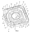
- FIG. 1 shows a condensate drain pan 20 configured for use in one particular air handling unit (AHU) of a heating ventilation and air conditioning (HVAC) system.
- AHU air handling unit
- HVAC heating ventilation and air conditioning
- the pan 20 has a channel 22 (well or other recess) shaped and dimensioned to receive dripping atmospheric condensate (water) from a heat absorption heat exchanger thereabove.
- the pan has a central vertical hole or aperture 24 (e.g., a circular planform hole having a central vertical axis 500) for passing an airflow to or from the heat exchanger.
- the exemplary channel 22 fully circumscribes/surrounds/encircles the aperture 24.
- this particular configuration includes peripheral apertures or holes 26 radially outboard of the channel for passing the airflow (e.g., if a leg 522 of the airflow is an inlet leg passing through the aperture to the heat exchanger, a leg 524 passing through the apertures 26 is a return/outlet/discharge leg returning the airflow to the room or other conditioned space).
- the exemplary pan has a generally square planform corresponding to a generally square housing planform of the AHU. Proximate one of the corners of the square, the channel 22 has a deepened region or well 30 which may receive a pump to pump out accumulated condensate.
- the exemplary pan generally includes an upper surface 34, a lower surface or underside 36, and a perimeter 38.
- the exemplary perimeter 38 includes portions 38-1, 38-2, 38-3, and 38-4, along respective sides of the square planform and portions 38-5, 38-6, 38-7, and 38-8 along relieved/removed corners of such planform adjacent the deepened area. Other greatly different overall shapes may be appropriate for other uses.
- the exemplary channel includes a base portion or bottom 40, an inboard (radially) sidewall 42 extending upward from the base, and an outboard sidewall 44 extending upward from the base.
- the sidewalls 42 and 44 have respective rims 45 and 46 along the pan upper surface.
- the exemplary base generally slopes toward the deepened area from a high point 48 approximately diametrically opposite the deepened area 30.
- Alternative implementations may involve a drain port in the drain pan and/or a remote pump.
- the exemplary pan further includes a boss 60 circumscribing the aperture 24 and a plurality of radial ribs 62 extending outward from the boss to a wall 64 inboard of the channel.
- FIG. 1 further shows a fresh air diverter 70 (discussed further below).
- the exemplary channel is purely a recessed/depressed region and does not have any penetration to the underside of the pan.
- An alternative implementation may have a penetration (e.g., hole) such as for a drain (e.g., if no pump or a remote pump is used).
- the pan includes an expanded porous polymeric substrate 80 ( FIG. 2 ) (e.g., an expanded bead material such as porous expanded polypropylene (PEPP)).
- an expanded porous polymeric substrate 80 e.g., an expanded bead material such as porous expanded polypropylene (PEPP)
- PEPP porous expanded polypropylene
- the crystallization provides water tightness.
- the substrate material may offer a combination of lightness, ease of manufacture, and sound deadening.
- FIG. 2 shows a cross-section of the channel with the crystallized layer shown as having a thickness T.
- An exemplary characteristic thickness T e.g., a median along the channel
- the exemplary embodiment has essentially no crystallization.
- FIG. 5 shows a mold 400 for molding the pan 20.
- the exemplary mold mold molds the pan upside-down, thus the mold has an upper half (e.g. essentially formed by a single piece 402, and a lower half (e.g., essentially formed by pieces 404 and 406 discussed below).
- Various conventional molding features such as seals, fittings, bosses, and the like are not shown for ease of illustration.
- a mold cavity 408 is defined between the mold halves.
- FIG. 1 the molding material
- FIG. 5 also shows a source of and means for introducing and evacuating fluid (e.g., steam) from the cavity 408.
- exemplary means include one or more steam lines 420 (shown schematically with valves) for introducing the steam and one or more similar lines 422 for evacuating the steam.
- the mold lower half includes a plenum 424 (e.g., formed between the pieces 404 and 406).
- the plenum is along and in close thermal communication with the portion 426 of the lower mold that molds the channel (and, if any, the broader region to be crystallized).
- FIG. 5 also shows a source of and means for introducing and evacuating fluid (e.g., steam) from the cavity 424.
- Exemplary means include one or more steam lines 428 (shown schematically with valves) for introducing the steam and one or more similar lines 430 for evacuating the steam.
- the mold sections are closed.
- the bead material is then injected so as to largely fill the cavity 408.
- Steam is then injected through the lines 420 so as to pass through the bead material and fuse (or further fuse) the beads at least partially.
- the mold is then water cooled via water passageways or a jacket (not shown) so as to cool and stabilize the molded piece.
- Crystallization steam is then injected via the lines 428 and evacuated via the lines 430 so as to locally heat the surface of the mold portion 426 to heat the channel surface of the molding and to locally melt/crystallize the material. This steam may be at a higher temperature than the fusing steam and the exposure time may be sufficient to cause the requisite melting.
- the part is then allowed to cure (e.g., via active and/or passive cooling of the mold).
- the mold halves are then separated and the pan extracted. There may then, if appropriate, be any trimming of flash/gates, and machining of additional features if required.
- the remaining system components may be made according to existing or yet-developed techniques appropriate for the system components. No changes to such components are necessarily required and the exemplary pan may be formed as a drop-in replacement or introduced as a running change in production replacing a similarly shaped/dimensioned baseline pan.
- the single-shot molding process may involve manufacturing cost reduction relative to a two-shot process (separate molding of the liner and the substrate).
- the liner may be relatively thin compared with the baseline. For example, pre-molding of a baseline liner may require the liner to be relatively thick. Accordingly, thinning of the liner may save material cost and/or reduce material consumption. Additionally, the thin liner may reduce sound transmission.
- FIG. 3 schematically shows an HVAC system 100 including a chiller 102 delivering a heat transfer liquid (e.g., water) to a plurality of air handling units (AHUs) 104.
- the exemplary chiller comprises a vapor compression system having a compressor 110, a heat rejection heat exchanger 112, an expansion device 114, and a heat absorption heat exchanger 116 along a recirculating refrigerant flowpath 118.
- This is a simplified configuration for purposes of illustration and various more detailed configurations may be implemented in practice. Except for modifications involving the drain pan, this may represent any of a number of existing or yet-developed configurations and may be manufactured using techniques and materials currently used or otherwise appropriate for such systems and may be used according to methods currently used or appropriate for such systems.
- the exemplary heat exchangers may refrigerant-water heat exchangers with respective recirculating water loops 120 and 122.
- the heat absorption heat exchanger water loop 122 extends toward and branches to the AHUs to deliver chilled water to the heat exchangers of each AHU.
- the heat rejection heat exchanger 112 is a refrigerant-air heat exchanger.
- FIG. 4 shows an AHU 104 including the pan 20 and having a housing body/chassis 190 (e.g., sheet steel).
- a heat exchanger 200 has a planform generally corresponding to and above the channel 22. A lower edge portion of the heat exchanger may be within the channel. The heat exchanger extends upward to an upper edge portion.
- the exemplary heat exchanger is a plate coil heat exchanger with plates oriented generally radially.
- the heat exchanger has a liquid inlet 202 and a liquid outlet 204.
- An exemplary fan 210 is mounted to the shaft of a motor 212.
- the exemplary motor is mounted to the top of a housing of the AHU surrounding the heat exchanger.
- the exemplary fan is mounted below the motor within the heat exchanger and has a lower axial inlet 220 and radial outlet 222.
- the fan draws air upward along the leg 522 through a central grill 230 along a bezel assembly 234 at the bottom of the housing and drives the air radially outward through the heat exchanger (between the coils and plates of the heat exchanger).
- the exemplary air is then directed downward through the apertures 26 along the leg 524 and, therefrom, out peripheral ducts 236 of the bezel assembly.
- FIG. 4 also shows the aforementioned pump 240 which may be connected to a discharge line 242 (e.g., a hose or a small flexible plastic tube) to discharge condensate water from the channel to a remote location.
- a discharge line 242 e.g., a hose or a small flexible plastic tube
- FIG. 6 shows a room interior 530.
- the AHU 104 is shown in a relatively simplified form with many components removed.
- the chassis 190 has a port/opening 192 connected to a fresh air intake duct 194 which admits/passes a fresh airflow 528.
- the flow 528 is diverted by the diverter 70 downward along the underside of the pan (e.g., between adjacent outlet ducts 236) of the bezel assembly of FIG. 4 so as to merge with the inlet flow 522 as a combined flow which passes through the fan and the coil.
Landscapes
- Engineering & Computer Science (AREA)
- Chemical & Material Sciences (AREA)
- Combustion & Propulsion (AREA)
- Mechanical Engineering (AREA)
- General Engineering & Computer Science (AREA)
- Devices For Blowing Cold Air, Devices For Blowing Warm Air, And Means For Preventing Water Condensation In Air Conditioning Units (AREA)
- Manufacture Of Porous Articles, And Recovery And Treatment Of Waste Products (AREA)
Abstract
Description
- The disclosure relates to refrigeration. More particularly, the disclosure relates to molded condensate collection pans/trays (drain pans).
- In exemplary refrigeration systems (e.g., HVAC systems, refrigerated cases, and the like). A heat absorption heat exchanger (evaporator) is exposed to air or a forced air stream. Water from the air condenses on the evaporator and is collected for removal.
- One exemplary group of collection systems involves collecting the condensate water in a drain pan. The drain pan may be waterproof to retain the water and may have sufficient thermal insulation to avoid the cool condensate chilling the outside of the pan and causing further condensation on the outside of the pan. One exemplary pan provides separate waterproof and insulating layers. The waterproof layer (liner) (e.g., polypropylene or polystyrene) may be molded in a first mold. The molded liner is transferred to a second mold wherein an insulative layer (e.g., expanded polystyrene) is overmolded to the liner.
- Such a pan may be used in an air handling unit (AHU) of an HVAC system. An exemplary HVAC system includes a chiller system with a vapor compression system providing chilled heat transfer liquid (e.g., water). The chilled water is delivered to individual AHUs. Each AHU includes a liquid-air heat exchanger receiving the chilled water. The AHU has a fan driving an airflow across the heat exchanger. An exemplary AHU is ceiling-mounted with a central underside inlet. A fan draws air up through the inlet and directs the air laterally outward to the heat exchanger which at least partially surrounds the fan. Air passes through the heat exchanger and may be directed back downward to peripheral outlets for discharge from the AHU. The drain pan may have a central aperture for passing the inlet airflow. The drain pan may have a channel circumscribing the inlet. The channel may correspond to the planform of the heat exchanger and may partially accommodate the heat exchanger. The channel may have a depressed/deeper region wherein a pump is located for discharging condensate liquid. The channel may generally slope toward the depressed region.
- One aspect of the disclosure involves a condensate drain pan having a porous expanded polymeric substrate and a crystallized polymeric layer atop the substrate. In various implementations, the polymeric substrate may be an expanded bead material (e.g., porous expanded polypropylene (PEPP)) and the crystallized polymeric layer may be a crystallized layer of such material.
- The pan may be made in a single shot molding process. The molding process may be followed by local crystallization to form the crystallized polymeric layer.
- Another aspect of the disclosure involves a method for manufacturing a molded product. The method comprises: assembling mold sections; injecting a bead material into a cavity of the assembled mold sections; locally heating so as to locally crystallize a polymeric layer; separating the mold sections; and extracting a molding having the locally crystallized layer.
- The details of one or more embodiments are set forth in the accompanying drawings and the description below. Other features, objects, and advantages will be apparent from the description and drawings, and from the claims.
-
-
FIG. 1 is a view of a drain pan of an air handling unit (AHU) of an HVAC system. -
FIG. 2 is a sectional view of the drain pan. -
FIG. 3 is a schematic view of an HVAC system. -
FIG. 4 is a view of an air handling unit (AHU) of the system ofFIG. 1 . -
FIG. 5 is a sectional view of a mold for molding the drain pan. -
FIG. 6 is a schematized sectional view of the AHU ofFIG. 4 . - Like reference numbers and designations in the various drawings indicate like elements.
-
FIG. 1 shows acondensate drain pan 20 configured for use in one particular air handling unit (AHU) of a heating ventilation and air conditioning (HVAC) system. Other configurations would be appropriate for use in other AHUs, use elsewhere in HVAC systems or non-HVAC use (e.g., refrigerated cases). Thepan 20 has a channel 22 (well or other recess) shaped and dimensioned to receive dripping atmospheric condensate (water) from a heat absorption heat exchanger thereabove. In the exemplary AHU implementation/configuration, the pan has a central vertical hole or aperture 24 (e.g., a circular planform hole having a central vertical axis 500) for passing an airflow to or from the heat exchanger. Theexemplary channel 22 fully circumscribes/surrounds/encircles theaperture 24. As discussed further below, this particular configuration includes peripheral apertures orholes 26 radially outboard of the channel for passing the airflow (e.g., if aleg 522 of the airflow is an inlet leg passing through the aperture to the heat exchanger, aleg 524 passing through theapertures 26 is a return/outlet/discharge leg returning the airflow to the room or other conditioned space). - As is discussed further below, the exemplary pan has a generally square planform corresponding to a generally square housing planform of the AHU. Proximate one of the corners of the square, the
channel 22 has a deepened region or well 30 which may receive a pump to pump out accumulated condensate. The exemplary pan generally includes anupper surface 34, a lower surface orunderside 36, and a perimeter 38. The exemplary perimeter 38 includes portions 38-1, 38-2, 38-3, and 38-4, along respective sides of the square planform and portions 38-5, 38-6, 38-7, and 38-8 along relieved/removed corners of such planform adjacent the deepened area. Other greatly different overall shapes may be appropriate for other uses. - The exemplary channel includes a base portion or
bottom 40, an inboard (radially)sidewall 42 extending upward from the base, and anoutboard sidewall 44 extending upward from the base. Thesidewalls respective rims high point 48 approximately diametrically opposite the deepenedarea 30. Alternative implementations may involve a drain port in the drain pan and/or a remote pump. The exemplary pan further includes aboss 60 circumscribing theaperture 24 and a plurality ofradial ribs 62 extending outward from the boss to awall 64 inboard of the channel.FIG. 1 further shows a fresh air diverter 70 (discussed further below). The exemplary channel is purely a recessed/depressed region and does not have any penetration to the underside of the pan. An alternative implementation may have a penetration (e.g., hole) such as for a drain (e.g., if no pump or a remote pump is used). - As is discussed further below, the pan includes an expanded porous polymeric substrate 80 (
FIG. 2 ) (e.g., an expanded bead material such as porous expanded polypropylene (PEPP)). Along thechannel 22, there is a crystallizedlayer 82 of the substrate material. The crystallization provides water tightness. The substrate material may offer a combination of lightness, ease of manufacture, and sound deadening. -
FIG. 2 shows a cross-section of the channel with the crystallized layer shown as having a thickness T. An exemplary characteristic thickness T (e.g., a median along the channel) is in excess of 0.2 millimeters, more narrowly, in excess of 0.3 millimeters or an exemplary 0.2-1.0 millimeters or 0.3-1.0 millimeters or 0.4-0.8 millimeters. Beyond the channel, the exemplary embodiment has essentially no crystallization. -
FIG. 5 shows amold 400 for molding thepan 20. The exemplary mold molds the pan upside-down, thus the mold has an upper half (e.g. essentially formed by asingle piece 402, and a lower half (e.g., essentially formed bypieces mold cavity 408 is defined between the mold halves. There may be multiple injection ports/gates 412 for introducing the molding material (e.g., EPP) from the source (not shown, e.g., of a conventional molding machine in which the mold halves are mounted).FIG. 5 also shows a source of and means for introducing and evacuating fluid (e.g., steam) from thecavity 408. Exemplary means include one or more steam lines 420 (shown schematically with valves) for introducing the steam and one or moresimilar lines 422 for evacuating the steam. - As is discussed further below, the mold lower half includes a plenum 424 (e.g., formed between the
pieces 404 and 406). The plenum is along and in close thermal communication with theportion 426 of the lower mold that molds the channel (and, if any, the broader region to be crystallized).FIG. 5 also shows a source of and means for introducing and evacuating fluid (e.g., steam) from thecavity 424. Exemplary means include one or more steam lines 428 (shown schematically with valves) for introducing the steam and one or moresimilar lines 430 for evacuating the steam. - In an exemplary method for manufacturing the pan, the mold sections are closed. The bead material is then injected so as to largely fill the
cavity 408. Steam is then injected through thelines 420 so as to pass through the bead material and fuse (or further fuse) the beads at least partially. The mold is then water cooled via water passageways or a jacket (not shown) so as to cool and stabilize the molded piece. Crystallization steam is then injected via thelines 428 and evacuated via thelines 430 so as to locally heat the surface of themold portion 426 to heat the channel surface of the molding and to locally melt/crystallize the material. This steam may be at a higher temperature than the fusing steam and the exposure time may be sufficient to cause the requisite melting. The part is then allowed to cure (e.g., via active and/or passive cooling of the mold). The mold halves are then separated and the pan extracted. There may then, if appropriate, be any trimming of flash/gates, and machining of additional features if required. - Other than the pan, the remaining system components may be made according to existing or yet-developed techniques appropriate for the system components. No changes to such components are necessarily required and the exemplary pan may be formed as a drop-in replacement or introduced as a running change in production replacing a similarly shaped/dimensioned baseline pan. Relative to the baseline, there may be one or more of several advantages depending upon implementation. For example, the single-shot molding process may involve manufacturing cost reduction relative to a two-shot process (separate molding of the liner and the substrate). Additionally, the liner may be relatively thin compared with the baseline. For example, pre-molding of a baseline liner may require the liner to be relatively thick. Accordingly, thinning of the liner may save material cost and/or reduce material consumption. Additionally, the thin liner may reduce sound transmission.
-
FIG. 3 schematically shows anHVAC system 100 including achiller 102 delivering a heat transfer liquid (e.g., water) to a plurality of air handling units (AHUs) 104. The exemplary chiller comprises a vapor compression system having acompressor 110, a heatrejection heat exchanger 112, anexpansion device 114, and a heatabsorption heat exchanger 116 along arecirculating refrigerant flowpath 118. This is a simplified configuration for purposes of illustration and various more detailed configurations may be implemented in practice. Except for modifications involving the drain pan, this may represent any of a number of existing or yet-developed configurations and may be manufactured using techniques and materials currently used or otherwise appropriate for such systems and may be used according to methods currently used or appropriate for such systems. - The exemplary heat exchangers may refrigerant-water heat exchangers with respective
recirculating water loops exchanger water loop 122 extends toward and branches to the AHUs to deliver chilled water to the heat exchangers of each AHU. In alternative implementations, the heatrejection heat exchanger 112 is a refrigerant-air heat exchanger. -
FIG. 4 shows anAHU 104 including thepan 20 and having a housing body/chassis 190 (e.g., sheet steel). Aheat exchanger 200 has a planform generally corresponding to and above thechannel 22. A lower edge portion of the heat exchanger may be within the channel. The heat exchanger extends upward to an upper edge portion. The exemplary heat exchanger is a plate coil heat exchanger with plates oriented generally radially. The heat exchanger has aliquid inlet 202 and aliquid outlet 204. Anexemplary fan 210 is mounted to the shaft of amotor 212. The exemplary motor is mounted to the top of a housing of the AHU surrounding the heat exchanger. The exemplary fan is mounted below the motor within the heat exchanger and has a loweraxial inlet 220 andradial outlet 222. In operation, the fan draws air upward along theleg 522 through acentral grill 230 along abezel assembly 234 at the bottom of the housing and drives the air radially outward through the heat exchanger (between the coils and plates of the heat exchanger). The exemplary air is then directed downward through theapertures 26 along theleg 524 and, therefrom, outperipheral ducts 236 of the bezel assembly. - As the air passes through the heat exchanger it is cooled causing moisture in the air to condense on the coils and plates and drip into the channel.
FIG. 4 also shows theaforementioned pump 240 which may be connected to a discharge line 242 (e.g., a hose or a small flexible plastic tube) to discharge condensate water from the channel to a remote location. -
FIG. 6 shows aroom interior 530. TheAHU 104 is shown in a relatively simplified form with many components removed. Thechassis 190 has a port/opening 192 connected to a freshair intake duct 194 which admits/passes afresh airflow 528. Theflow 528 is diverted by thediverter 70 downward along the underside of the pan (e.g., between adjacent outlet ducts 236) of the bezel assembly ofFIG. 4 so as to merge with theinlet flow 522 as a combined flow which passes through the fan and the coil. - Although an embodiment is described above in detail, such description is not intended for limiting the scope of the present disclosure. It will be understood that various modifications may be made without departing from the scope of the disclosure. For example, when implemented in the redesign or reengineering of an existing system, details of the existing system may influence details of any particular implementation. Accordingly, other embodiments are within the scope of the following claims.
Claims (15)
- A condensate drain pan (20) comprising:a porous expanded polymeric substrate (80); anda crystallized polymeric layer (82) atop the substrate.
- The pan of claim 1 wherein at least one of:the polymeric substrate (80) comprises expanded bead material; andthe crystallized polymeric layer (82) is a crystallized layer of the polymeric material of the polymeric substrate (80).
- The pan of claim 1 or 2 wherein:the polymeric substrate (80) comprises porous expanded polypropylene (PEPP).
- The pan of any preceding claim wherein:along a majority of a well (22) of the pan (20), the layer (82) is at least 0.2mm thick.
- The pan of any preceding claim wherein:a median thickness of the layer (82) is 0.2-1.0mm.
- The pan of any preceding claim wherein:the substrate (80) is shaped having:a central aperture (24); anda channel (22) encircling the aperture, the layer (82) being along the channel (22).
- The pan of claim 6 wherein:the pan (20) has a generally square planform; andthe channel (22) includes a deepened area (30) near one corner of the square planform and generally slopes toward the deepened area (30).
- A system comprising:the pan (20) of any preceding claim; anda heat rejection heat exchanger (120; 200) positioned to discharge condensate to the pan (20).
- The system of claim 8 wherein:the pan (20) and heat rejection heat exchanger (120; 200) are part of an air handling unit (104); andthe air handling unit (104) further comprises a fan (210) positioned to drive an airflow across the heat rejection heat exchanger (120; 200);and, optionally, further comprising:a chiller (102) coupled to the heat rejection heat exchanger (120; 200) to deliver chilled liquid to the heat rejection heat exchanger (200).
- The system of claim 8 or 9 further comprising:a pump (240) positioned to discharge condensate from the pan (20).
- The system of claim 8, 9 or 10 being a vapor compression system comprising:a compressor (110);a heat absorption heat exchanger (116) downstream of the compressor (110) along a refrigerant flowpath (118);said heat absorption heat exchanger (116) downstream of the heat rejection heat exchanger (120) along the refrigerant flowpath (118); andsaid pan (20).
- A method for manufacturing the pan of any of claims 1 to 7 comprising:assembling mold sections (402, 404, 406);injecting a bead material into a cavity (48) of the assembled mold sections (402, 404, 406);heating so as to crystallize said polymeric layer (82);separating the mold sections (402, 404, 406); andextracting the drain pan (20).
- A method for manufacturing a molded product, the method comprising:assembling mold sections (402, 404, 406);injecting a bead material into a cavity (408) of the assembled mold sections (102, 404, 406);locally heating so as to locally crystallize a polymeric layer (82);separating the mold sections (402, 404, 406); andextracting a molding having said locally crystallized layer (82).
- The method of claim 12 or 13 wherein:a steam injection into the cavity (408) at least partially fuses the material; andthe heating comprises a further steam injection, not into the cavity (408) or a further steam injection, into a separate cavity (424).
- The method of claim 14 wherein:the further steam injection is more locally confined than the prior steam injection.
Applications Claiming Priority (1)
| Application Number | Priority Date | Filing Date | Title |
|---|---|---|---|
| US201161565706P | 2011-12-01 | 2011-12-01 |
Publications (3)
| Publication Number | Publication Date |
|---|---|
| EP2600075A2 true EP2600075A2 (en) | 2013-06-05 |
| EP2600075A3 EP2600075A3 (en) | 2017-03-15 |
| EP2600075B1 EP2600075B1 (en) | 2021-08-11 |
Family
ID=47294703
Family Applications (1)
| Application Number | Title | Priority Date | Filing Date |
|---|---|---|---|
| EP12194869.9A Active EP2600075B1 (en) | 2011-12-01 | 2012-11-29 | Molded parts and methods of manufacture |
Country Status (2)
| Country | Link |
|---|---|
| EP (1) | EP2600075B1 (en) |
| ES (1) | ES2882706T3 (en) |
Cited By (3)
| Publication number | Priority date | Publication date | Assignee | Title |
|---|---|---|---|---|
| JP2016099051A (en) * | 2014-11-21 | 2016-05-30 | 株式会社富士通ゼネラル | Embedded ceiling air conditioner |
| JP2019132476A (en) * | 2018-01-30 | 2019-08-08 | 三菱重工サーマルシステムズ株式会社 | Ceiling embedded type air conditioner |
| US10871306B2 (en) | 2019-01-02 | 2020-12-22 | Johnson Controls Technology Company | Modular drain pans for HVAC systems |
Family Cites Families (8)
| Publication number | Priority date | Publication date | Assignee | Title |
|---|---|---|---|---|
| JPS5575722U (en) * | 1978-11-20 | 1980-05-24 | ||
| JPH0587361A (en) * | 1991-09-25 | 1993-04-06 | Asahi Chem Ind Co Ltd | Air conditioner drain pan |
| US5225448A (en) * | 1992-11-19 | 1993-07-06 | The Goodyear Tire & Rubber Company | Preparation of porous polyester beads |
| JP3081491B2 (en) * | 1995-02-28 | 2000-08-28 | 三洋電機株式会社 | Drain pan and air conditioner equipped with the drain pan |
| JPH1122998A (en) * | 1997-07-02 | 1999-01-26 | Sanyo Electric Co Ltd | Drain pan for air conditioner |
| JP3695977B2 (en) * | 1999-02-15 | 2005-09-14 | ダイセル化学工業株式会社 | Polypropylene film |
| JP2001205654A (en) * | 2000-01-25 | 2001-07-31 | Sekisui Plastics Co Ltd | Thermoplastic polyester resin foam sheet and method for producing foam |
| JP5463000B2 (en) * | 2007-11-27 | 2014-04-02 | 三菱重工業株式会社 | Indoor unit for air conditioning |
-
2012
- 2012-11-29 EP EP12194869.9A patent/EP2600075B1/en active Active
- 2012-11-29 ES ES12194869T patent/ES2882706T3/en active Active
Non-Patent Citations (1)
| Title |
|---|
| None |
Cited By (3)
| Publication number | Priority date | Publication date | Assignee | Title |
|---|---|---|---|---|
| JP2016099051A (en) * | 2014-11-21 | 2016-05-30 | 株式会社富士通ゼネラル | Embedded ceiling air conditioner |
| JP2019132476A (en) * | 2018-01-30 | 2019-08-08 | 三菱重工サーマルシステムズ株式会社 | Ceiling embedded type air conditioner |
| US10871306B2 (en) | 2019-01-02 | 2020-12-22 | Johnson Controls Technology Company | Modular drain pans for HVAC systems |
Also Published As
| Publication number | Publication date |
|---|---|
| EP2600075B1 (en) | 2021-08-11 |
| ES2882706T3 (en) | 2021-12-02 |
| EP2600075A3 (en) | 2017-03-15 |
Similar Documents
| Publication | Publication Date | Title |
|---|---|---|
| CN102645068B (en) | Air duct component and refrigerator with same | |
| CN102428331B (en) | No-Frost Refrigeration Device | |
| CN109751808B (en) | Air-cooled refrigeration equipment | |
| WO2015188623A1 (en) | Air-cooled refrigerator | |
| US11306960B2 (en) | Refrigerator having detachable cooling module | |
| CN209840496U (en) | Refrigerator with novel air duct structure | |
| EP2600075B1 (en) | Molded parts and methods of manufacture | |
| CN108278808A (en) | A kind of refrigerator of shower wind air channel structure | |
| CN102927743B (en) | Ducting assembly and the refrigerator with this ducting assembly | |
| CN104634046B (en) | Wind cooling refrigerator | |
| JP2019219112A (en) | refrigerator | |
| CN106123449B (en) | A kind of air channel structure and the refrigerator using the air channel structure | |
| JP2003202176A (en) | refrigerator | |
| US6571571B2 (en) | Refrigeration unit | |
| CN219810121U (en) | Refrigerator | |
| CN1928466A (en) | Refrigerator | |
| CN105042986B (en) | refrigerator | |
| EP4006458B1 (en) | Refrigerator with obliquely arranged evaporator | |
| CN111609609B (en) | Refrigerator using cross-flow fan for heat dissipation | |
| CN212778124U (en) | Refrigerator with air return inlet and air supply duct arranged on opposite side walls | |
| CN207674789U (en) | Refrigeration equipment | |
| CN219776091U (en) | Return air cover and freezer | |
| CN219810092U (en) | Freezer | |
| CN203964513U (en) | Refrigerator | |
| CN220017782U (en) | Refrigerating unit for refrigerating equipment and refrigerating equipment |
Legal Events
| Date | Code | Title | Description |
|---|---|---|---|
| PUAI | Public reference made under article 153(3) epc to a published international application that has entered the european phase |
Free format text: ORIGINAL CODE: 0009012 |
|
| AK | Designated contracting states |
Kind code of ref document: A2 Designated state(s): AL AT BE BG CH CY CZ DE DK EE ES FI FR GB GR HR HU IE IS IT LI LT LU LV MC MK MT NL NO PL PT RO RS SE SI SK SM TR |
|
| AX | Request for extension of the european patent |
Extension state: BA ME |
|
| PUAL | Search report despatched |
Free format text: ORIGINAL CODE: 0009013 |
|
| AK | Designated contracting states |
Kind code of ref document: A3 Designated state(s): AL AT BE BG CH CY CZ DE DK EE ES FI FR GB GR HR HU IE IS IT LI LT LU LV MC MK MT NL NO PL PT RO RS SE SI SK SM TR |
|
| AX | Request for extension of the european patent |
Extension state: BA ME |
|
| RIC1 | Information provided on ipc code assigned before grant |
Ipc: F24F 13/22 20060101AFI20170203BHEP Ipc: B29C 51/00 20060101ALI20170203BHEP |
|
| STAA | Information on the status of an ep patent application or granted ep patent |
Free format text: STATUS: REQUEST FOR EXAMINATION WAS MADE |
|
| 17P | Request for examination filed |
Effective date: 20170915 |
|
| RBV | Designated contracting states (corrected) |
Designated state(s): AL AT BE BG CH CY CZ DE DK EE ES FI FR GB GR HR HU IE IS IT LI LT LU LV MC MK MT NL NO PL PT RO RS SE SI SK SM TR |
|
| STAA | Information on the status of an ep patent application or granted ep patent |
Free format text: STATUS: EXAMINATION IS IN PROGRESS |
|
| 17Q | First examination report despatched |
Effective date: 20190415 |
|
| REG | Reference to a national code |
Ref country code: DE Ref legal event code: R079 Ref document number: 602012076355 Country of ref document: DE Free format text: PREVIOUS MAIN CLASS: F24F0013220000 Ipc: B32B0005180000 |
|
| GRAP | Despatch of communication of intention to grant a patent |
Free format text: ORIGINAL CODE: EPIDOSNIGR1 |
|
| STAA | Information on the status of an ep patent application or granted ep patent |
Free format text: STATUS: GRANT OF PATENT IS INTENDED |
|
| RIC1 | Information provided on ipc code assigned before grant |
Ipc: B32B 5/14 20060101ALN20210326BHEP Ipc: F25D 21/14 20060101ALN20210326BHEP Ipc: B32B 27/32 20060101ALI20210326BHEP Ipc: B32B 27/06 20060101ALI20210326BHEP Ipc: F24F 13/22 20060101ALI20210326BHEP Ipc: B32B 5/22 20060101ALI20210326BHEP Ipc: B32B 5/18 20060101AFI20210326BHEP |
|
| INTG | Intention to grant announced |
Effective date: 20210420 |
|
| GRAS | Grant fee paid |
Free format text: ORIGINAL CODE: EPIDOSNIGR3 |
|
| GRAA | (expected) grant |
Free format text: ORIGINAL CODE: 0009210 |
|
| STAA | Information on the status of an ep patent application or granted ep patent |
Free format text: STATUS: THE PATENT HAS BEEN GRANTED |
|
| AK | Designated contracting states |
Kind code of ref document: B1 Designated state(s): AL AT BE BG CH CY CZ DE DK EE ES FI FR GB GR HR HU IE IS IT LI LT LU LV MC MK MT NL NO PL PT RO RS SE SI SK SM TR |
|
| REG | Reference to a national code |
Ref country code: GB Ref legal event code: FG4D |
|
| REG | Reference to a national code |
Ref country code: CH Ref legal event code: EP |
|
| REG | Reference to a national code |
Ref country code: DE Ref legal event code: R096 Ref document number: 602012076355 Country of ref document: DE |
|
| REG | Reference to a national code |
Ref country code: NL Ref legal event code: FP Ref country code: IE Ref legal event code: FG4D Ref country code: AT Ref legal event code: REF Ref document number: 1418974 Country of ref document: AT Kind code of ref document: T Effective date: 20210915 |
|
| REG | Reference to a national code |
Ref country code: ES Ref legal event code: FG2A Ref document number: 2882706 Country of ref document: ES Kind code of ref document: T3 Effective date: 20211202 |
|
| REG | Reference to a national code |
Ref country code: LT Ref legal event code: MG9D |
|
| REG | Reference to a national code |
Ref country code: AT Ref legal event code: MK05 Ref document number: 1418974 Country of ref document: AT Kind code of ref document: T Effective date: 20210811 |
|
| PG25 | Lapsed in a contracting state [announced via postgrant information from national office to epo] |
Ref country code: HR Free format text: LAPSE BECAUSE OF FAILURE TO SUBMIT A TRANSLATION OF THE DESCRIPTION OR TO PAY THE FEE WITHIN THE PRESCRIBED TIME-LIMIT Effective date: 20210811 Ref country code: SE Free format text: LAPSE BECAUSE OF FAILURE TO SUBMIT A TRANSLATION OF THE DESCRIPTION OR TO PAY THE FEE WITHIN THE PRESCRIBED TIME-LIMIT Effective date: 20210811 Ref country code: AT Free format text: LAPSE BECAUSE OF FAILURE TO SUBMIT A TRANSLATION OF THE DESCRIPTION OR TO PAY THE FEE WITHIN THE PRESCRIBED TIME-LIMIT Effective date: 20210811 Ref country code: BG Free format text: LAPSE BECAUSE OF FAILURE TO SUBMIT A TRANSLATION OF THE DESCRIPTION OR TO PAY THE FEE WITHIN THE PRESCRIBED TIME-LIMIT Effective date: 20211111 Ref country code: LT Free format text: LAPSE BECAUSE OF FAILURE TO SUBMIT A TRANSLATION OF THE DESCRIPTION OR TO PAY THE FEE WITHIN THE PRESCRIBED TIME-LIMIT Effective date: 20210811 Ref country code: RS Free format text: LAPSE BECAUSE OF FAILURE TO SUBMIT A TRANSLATION OF THE DESCRIPTION OR TO PAY THE FEE WITHIN THE PRESCRIBED TIME-LIMIT Effective date: 20210811 Ref country code: PT Free format text: LAPSE BECAUSE OF FAILURE TO SUBMIT A TRANSLATION OF THE DESCRIPTION OR TO PAY THE FEE WITHIN THE PRESCRIBED TIME-LIMIT Effective date: 20211213 Ref country code: NO Free format text: LAPSE BECAUSE OF FAILURE TO SUBMIT A TRANSLATION OF THE DESCRIPTION OR TO PAY THE FEE WITHIN THE PRESCRIBED TIME-LIMIT Effective date: 20211111 Ref country code: FI Free format text: LAPSE BECAUSE OF FAILURE TO SUBMIT A TRANSLATION OF THE DESCRIPTION OR TO PAY THE FEE WITHIN THE PRESCRIBED TIME-LIMIT Effective date: 20210811 |
|
| PG25 | Lapsed in a contracting state [announced via postgrant information from national office to epo] |
Ref country code: PL Free format text: LAPSE BECAUSE OF FAILURE TO SUBMIT A TRANSLATION OF THE DESCRIPTION OR TO PAY THE FEE WITHIN THE PRESCRIBED TIME-LIMIT Effective date: 20210811 Ref country code: LV Free format text: LAPSE BECAUSE OF FAILURE TO SUBMIT A TRANSLATION OF THE DESCRIPTION OR TO PAY THE FEE WITHIN THE PRESCRIBED TIME-LIMIT Effective date: 20210811 Ref country code: GR Free format text: LAPSE BECAUSE OF FAILURE TO SUBMIT A TRANSLATION OF THE DESCRIPTION OR TO PAY THE FEE WITHIN THE PRESCRIBED TIME-LIMIT Effective date: 20211112 |
|
| PG25 | Lapsed in a contracting state [announced via postgrant information from national office to epo] |
Ref country code: DK Free format text: LAPSE BECAUSE OF FAILURE TO SUBMIT A TRANSLATION OF THE DESCRIPTION OR TO PAY THE FEE WITHIN THE PRESCRIBED TIME-LIMIT Effective date: 20210811 |
|
| REG | Reference to a national code |
Ref country code: DE Ref legal event code: R097 Ref document number: 602012076355 Country of ref document: DE |
|
| PG25 | Lapsed in a contracting state [announced via postgrant information from national office to epo] |
Ref country code: SM Free format text: LAPSE BECAUSE OF FAILURE TO SUBMIT A TRANSLATION OF THE DESCRIPTION OR TO PAY THE FEE WITHIN THE PRESCRIBED TIME-LIMIT Effective date: 20210811 Ref country code: SK Free format text: LAPSE BECAUSE OF FAILURE TO SUBMIT A TRANSLATION OF THE DESCRIPTION OR TO PAY THE FEE WITHIN THE PRESCRIBED TIME-LIMIT Effective date: 20210811 Ref country code: RO Free format text: LAPSE BECAUSE OF FAILURE TO SUBMIT A TRANSLATION OF THE DESCRIPTION OR TO PAY THE FEE WITHIN THE PRESCRIBED TIME-LIMIT Effective date: 20210811 Ref country code: EE Free format text: LAPSE BECAUSE OF FAILURE TO SUBMIT A TRANSLATION OF THE DESCRIPTION OR TO PAY THE FEE WITHIN THE PRESCRIBED TIME-LIMIT Effective date: 20210811 Ref country code: CZ Free format text: LAPSE BECAUSE OF FAILURE TO SUBMIT A TRANSLATION OF THE DESCRIPTION OR TO PAY THE FEE WITHIN THE PRESCRIBED TIME-LIMIT Effective date: 20210811 Ref country code: AL Free format text: LAPSE BECAUSE OF FAILURE TO SUBMIT A TRANSLATION OF THE DESCRIPTION OR TO PAY THE FEE WITHIN THE PRESCRIBED TIME-LIMIT Effective date: 20210811 |
|
| PLBE | No opposition filed within time limit |
Free format text: ORIGINAL CODE: 0009261 |
|
| STAA | Information on the status of an ep patent application or granted ep patent |
Free format text: STATUS: NO OPPOSITION FILED WITHIN TIME LIMIT |
|
| PG25 | Lapsed in a contracting state [announced via postgrant information from national office to epo] |
Ref country code: MC Free format text: LAPSE BECAUSE OF FAILURE TO SUBMIT A TRANSLATION OF THE DESCRIPTION OR TO PAY THE FEE WITHIN THE PRESCRIBED TIME-LIMIT Effective date: 20210811 |
|
| REG | Reference to a national code |
Ref country code: CH Ref legal event code: PL |
|
| 26N | No opposition filed |
Effective date: 20220512 |
|
| GBPC | Gb: european patent ceased through non-payment of renewal fee |
Effective date: 20211129 |
|
| PG25 | Lapsed in a contracting state [announced via postgrant information from national office to epo] |
Ref country code: LU Free format text: LAPSE BECAUSE OF NON-PAYMENT OF DUE FEES Effective date: 20211129 Ref country code: IT Free format text: LAPSE BECAUSE OF FAILURE TO SUBMIT A TRANSLATION OF THE DESCRIPTION OR TO PAY THE FEE WITHIN THE PRESCRIBED TIME-LIMIT Effective date: 20210811 Ref country code: BE Free format text: LAPSE BECAUSE OF NON-PAYMENT OF DUE FEES Effective date: 20211130 |
|
| REG | Reference to a national code |
Ref country code: BE Ref legal event code: MM Effective date: 20211130 |
|
| PG25 | Lapsed in a contracting state [announced via postgrant information from national office to epo] |
Ref country code: SI Free format text: LAPSE BECAUSE OF FAILURE TO SUBMIT A TRANSLATION OF THE DESCRIPTION OR TO PAY THE FEE WITHIN THE PRESCRIBED TIME-LIMIT Effective date: 20210811 Ref country code: LI Free format text: LAPSE BECAUSE OF NON-PAYMENT OF DUE FEES Effective date: 20211130 Ref country code: CH Free format text: LAPSE BECAUSE OF NON-PAYMENT OF DUE FEES Effective date: 20211130 |
|
| PG25 | Lapsed in a contracting state [announced via postgrant information from national office to epo] |
Ref country code: IE Free format text: LAPSE BECAUSE OF NON-PAYMENT OF DUE FEES Effective date: 20211129 Ref country code: GB Free format text: LAPSE BECAUSE OF NON-PAYMENT OF DUE FEES Effective date: 20211129 |
|
| PG25 | Lapsed in a contracting state [announced via postgrant information from national office to epo] |
Ref country code: HU Free format text: LAPSE BECAUSE OF FAILURE TO SUBMIT A TRANSLATION OF THE DESCRIPTION OR TO PAY THE FEE WITHIN THE PRESCRIBED TIME-LIMIT; INVALID AB INITIO Effective date: 20121129 Ref country code: CY Free format text: LAPSE BECAUSE OF FAILURE TO SUBMIT A TRANSLATION OF THE DESCRIPTION OR TO PAY THE FEE WITHIN THE PRESCRIBED TIME-LIMIT Effective date: 20210811 |
|
| PG25 | Lapsed in a contracting state [announced via postgrant information from national office to epo] |
Ref country code: MK Free format text: LAPSE BECAUSE OF FAILURE TO SUBMIT A TRANSLATION OF THE DESCRIPTION OR TO PAY THE FEE WITHIN THE PRESCRIBED TIME-LIMIT Effective date: 20210811 |
|
| PG25 | Lapsed in a contracting state [announced via postgrant information from national office to epo] |
Ref country code: TR Free format text: LAPSE BECAUSE OF FAILURE TO SUBMIT A TRANSLATION OF THE DESCRIPTION OR TO PAY THE FEE WITHIN THE PRESCRIBED TIME-LIMIT Effective date: 20210811 |
|
| PG25 | Lapsed in a contracting state [announced via postgrant information from national office to epo] |
Ref country code: MT Free format text: LAPSE BECAUSE OF FAILURE TO SUBMIT A TRANSLATION OF THE DESCRIPTION OR TO PAY THE FEE WITHIN THE PRESCRIBED TIME-LIMIT Effective date: 20210811 |
|
| PGFP | Annual fee paid to national office [announced via postgrant information from national office to epo] |
Ref country code: NL Payment date: 20241022 Year of fee payment: 13 |
|
| PGFP | Annual fee paid to national office [announced via postgrant information from national office to epo] |
Ref country code: ES Payment date: 20241202 Year of fee payment: 13 |
|
| PGFP | Annual fee paid to national office [announced via postgrant information from national office to epo] |
Ref country code: DE Payment date: 20251022 Year of fee payment: 14 |
|
| PGFP | Annual fee paid to national office [announced via postgrant information from national office to epo] |
Ref country code: FR Payment date: 20251023 Year of fee payment: 14 |