EP2600072A1 - Humidifier - Google Patents
Humidifier Download PDFInfo
- Publication number
- EP2600072A1 EP2600072A1 EP11812230.8A EP11812230A EP2600072A1 EP 2600072 A1 EP2600072 A1 EP 2600072A1 EP 11812230 A EP11812230 A EP 11812230A EP 2600072 A1 EP2600072 A1 EP 2600072A1
- Authority
- EP
- European Patent Office
- Prior art keywords
- tank
- section
- main body
- tray
- protruding
- Prior art date
- Legal status (The legal status is an assumption and is not a legal conclusion. Google has not performed a legal analysis and makes no representation as to the accuracy of the status listed.)
- Withdrawn
Links
- XLYOFNOQVPJJNP-UHFFFAOYSA-N water Substances O XLYOFNOQVPJJNP-UHFFFAOYSA-N 0.000 claims description 53
- 230000002093 peripheral effect Effects 0.000 claims description 15
- 230000005484 gravity Effects 0.000 abstract description 6
- 238000009423 ventilation Methods 0.000 description 16
- 238000003780 insertion Methods 0.000 description 12
- 230000037431 insertion Effects 0.000 description 12
- 230000004048 modification Effects 0.000 description 8
- 238000012986 modification Methods 0.000 description 8
- 239000000463 material Substances 0.000 description 7
- 230000008016 vaporization Effects 0.000 description 7
- 238000009834 vaporization Methods 0.000 description 7
- 238000004140 cleaning Methods 0.000 description 5
- 230000001877 deodorizing effect Effects 0.000 description 4
- 239000000428 dust Substances 0.000 description 4
- 238000011045 prefiltration Methods 0.000 description 4
- 230000000694 effects Effects 0.000 description 3
- 239000002245 particle Substances 0.000 description 3
- 238000005192 partition Methods 0.000 description 3
- 238000012423 maintenance Methods 0.000 description 2
- 238000011144 upstream manufacturing Methods 0.000 description 2
- 238000006073 displacement reaction Methods 0.000 description 1
- 239000004744 fabric Substances 0.000 description 1
- 238000004519 manufacturing process Methods 0.000 description 1
- 230000013011 mating Effects 0.000 description 1
- 210000003205 muscle Anatomy 0.000 description 1
- 239000011347 resin Substances 0.000 description 1
- 229920005989 resin Polymers 0.000 description 1
Images





Classifications
-
- F—MECHANICAL ENGINEERING; LIGHTING; HEATING; WEAPONS; BLASTING
- F24—HEATING; RANGES; VENTILATING
- F24F—AIR-CONDITIONING; AIR-HUMIDIFICATION; VENTILATION; USE OF AIR CURRENTS FOR SCREENING
- F24F6/00—Air-humidification, e.g. cooling by humidification
- F24F6/02—Air-humidification, e.g. cooling by humidification by evaporation of water in the air
- F24F6/06—Air-humidification, e.g. cooling by humidification by evaporation of water in the air using moving unheated wet elements
-
- F—MECHANICAL ENGINEERING; LIGHTING; HEATING; WEAPONS; BLASTING
- F24—HEATING; RANGES; VENTILATING
- F24F—AIR-CONDITIONING; AIR-HUMIDIFICATION; VENTILATION; USE OF AIR CURRENTS FOR SCREENING
- F24F6/00—Air-humidification, e.g. cooling by humidification
- F24F2006/008—Air-humidifier with water reservoir
-
- F—MECHANICAL ENGINEERING; LIGHTING; HEATING; WEAPONS; BLASTING
- F24—HEATING; RANGES; VENTILATING
- F24F—AIR-CONDITIONING; AIR-HUMIDIFICATION; VENTILATION; USE OF AIR CURRENTS FOR SCREENING
- F24F2221/00—Details or features not otherwise provided for
- F24F2221/12—Details or features not otherwise provided for transportable
Definitions
- This invention relates to a humidifier, and particularly to a humidifier in which water fed from a tank to a tray is vaporized in a humidification element.
- the present invention addresses the problem of providing a humidifier in which the weight load of the tank is used to fit the tank and reduce the burden on the user.
- a humidifier comprises a main body, a humidification means, and a tank.
- the humidification means is housed in the main body.
- the tank is fitted to the main body from a sideward direction relative to the main body, and feeds water to the humidification means.
- a support section for supporting the tank is provided to the main body. The support section comes into contact with a predetermined position on the tank when the tank is being fitted.
- the tank has a protruding section formed on an upper half portion, the protruding section protruding further towards the main-body side than any portion on a lower half. The tank rotates about a vicinity of the support section and is thereby fitted to the main body.
- a humidifier according to a second aspect of the present invention is the humidifier according to the first aspect, wherein the humidification means includes a circular disc-shaped humidification element. An outer peripheral surface of the humidification element faces the tank. A concave section, which is recessed in a direction away from a center of the humidification element, is formed at a portion, of the tank, that corresponds to the height position of the center. The protruding section is positioned further above the concave section.
- a humidifier according to a third aspect of the present invention is the humidifier according to the second aspect, wherein a second protruding section protruding towards the main-body side is formed further below the concave section of the tank.
- a humidifier according to a fourth aspect of the present invention is the humidifier according to the first aspect, further comprising a fan.
- the fan generates an airflow passing from an obverse surface to a reverse surface of the humidification element.
- the fan also includes a fan rotor and a casing.
- the fan rotor is located downstream of the humidification element.
- the casing surrounds the fan rotor and guides air blown in a centrifugal direction from the fan rotor, the air being guided towards an outlet port above the fan rotor.
- the casing also has an inwardly curved section curving inwards in front of the outlet port. The protruding section of the tank protrudes towards the inwardly curved section.
- the protruding section protrudes so as to fit into the inwardly curved section originally provided to the casing. Therefore, there is no need to provide an additional space for the protruding section, and space is used in an effective manner.
- a humidifier according to a fifth embodiment of the present invention is the humidifier according to the first aspect, further comprising a tray and a fan.
- the tray together with the main body, covers the humidification element.
- the fan generates an airflow passing from an obverse surface to a reverse surface of the humidification element.
- the tray has a side plate.
- the side plate is located between the tank and an outer peripheral surface of the humidification element.
- the side plate has a curved section.
- the curved section curves along a circumferential surface of the humidification element at a position higher than at least a center of rotation of the humidification element. The curved section is pressed by the protruding section of the tank.
- the protruding section presses the curved section, whereby the gap between the side plate and the main body further narrowed and the ventilation resistance is increased. Therefore, there is a decrease in the amount of bypass air, which enters through the gap between the side plate and the main body and is taken into the fan without passing through the humidification element.
- a humidifier according to a sixth aspect of the present invention is the humidifier according to a fifth aspect, wherein an elastic member is provided between the curved section and the protruding section.
- the humidifier according to the first aspect of the present invention when, in the course of the user bringing the tank nearer the main body while causing the tank to rotate, the center of gravity of the protruding section has shifted further towards the main body than the vertical plane passing through the center of rotation, the own weight of the tank causes the tank to move towards the main-body side. Therefore, a smaller pushing-in force is required from the user, and the burden when fitting the tank is reduced.
- forming the concave section increases the tendency of the tank to lean towards the direction in which the protruding section protrudes. Therefore, an even smaller pushing-in force is required from the user when the tank is being brought nearer the main body while being caused to rotate.
- the space between the outer peripheral surface of the humidification element and the tank facing the outer peripheral surface is smaller, and the amount of wasted space is reduced compared to conventional articles in which a straight tank is used.
- the protruding section protrudes so as to fit into the inwardly curved section. Therefore, there is no need to provide an additional space for the protruding section, and space is used in an effective manner.
- the protruding section presses the curved section, whereby the gap between the side plate and the main body further narrowed and the ventilation resistance is increased. Therefore, there is a decrease in the amount of bypass air, which enters through the gap between the side plate and the main body and is taken into the fan without passing through the humidification element.
- the elastic member fills the gap between the curved section and the protruding section, and the pressing force of the protruding section is therefore transmitted to the curved section in a reliable manner.
- FIG 1 is a perspective view of a humidifier according to an embodiment of the present invention as viewed diagonally from the front.
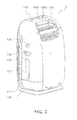
- FIG 2 is a perspective view of the humidifier according to an embodiment of the present invention as viewed diagonally from the rear.
- the humidifier 1 comprises a main body 10 having a rounded shape overall.
- the humidifier 1 has a humidification function and an air-cleaning function. The user may select the air-cleaning function only; however, when the humidification function is selected, the air-cleaning function is always enabled alongside.
- the main body 10 includes a front-surface panel 110, a casing 120, a bottom plate 130, and a control panel 140.
- the front-surface panel 110 is held at the front of the casing 120 so that attachment and detachment are possible without using a tool or similar means.
- the bottom plate 130 is screwed to the bottom of the casing 120.
- the control panel 140 is fixed to a top surface of the casing 120.
- a power switch 140a for selecting the RUN and STOP states of the humidifier 1 a humidification switch 140b for selecting EXECUTE and DISCONTINUE with regards to the humidification function, and similar elements are installed on the control panel 140. Signals from switch operations are transmitted to a control unit (not shown) internally provided in the main body 10.
- the main body 10 has an inlet port 10a on a side section.
- the inlet port 10a is surrounded by a side section of the front-surface panel 110 and a side section of the casing 120.
- the main body 10 also has an outlet port 10b on an upper section.
- the outlet port 10b is positioned on the upper section of the casing 120 and behind the control panel 140.
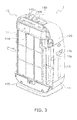
- FIG. 3 is a perspective view of the humidifier shown in FIG 1 from which the front-surface panel has been removed.
- air taken in from the inlet port 10a passes through a filter unit 11 fitted to the front surface of the casing 120.
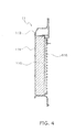
- FIG. 4 is a vertical cross-section view of the filter unit.
- a pre-filter 114, a HEPA filter 116, and a deodorizing element 118 are held by a filter casing 112 in the sequence listed from the upstream side.
- the pre-filter 114 is a thin and soft netting made from a resin, and removes large dust particles and similar matter contained in the air.
- the HEPA filter 116 removes finer dust and similar matter that cannot be removed by the pre-filter 114.
- the deodorizing element 118 absorbs unpleasant odor components contained in the air.
- FIG 5 is a perspective view of the humidifier shown in FIG. 2 when the side-surface door of the humidifier is open.
- an opening 120a extending across a part of a side surface and a part of a back surface of the casing 120 is formed in the casing 120.
- a space is formed from the opening 120a towards the far side of the casing 120, and a tank 16 is housed in this space. Since the tank 16 is screwed to the inner-surface side of the side-surface door 13, the side-surface door 13 and the tank 16 moves in an integral manner.
- the opening 120a is closed by the side-surface door 13 (see FIGS. 1 and 2 ).
- the side-surface door 13 can turn, about a lower edge, in the direction in which an upper edge moves away from the casing 120. Pulling a handle 13a causes the upper edge of the side-surface door 13 to move away from the casing 120 and the tank 16 to be revealed.
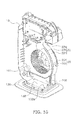
- FIG 6 is a perspective view of the humidifier in a state in which the front-surface panel, the casing, the filter unit, and the tank have been detached from the main body.
- FIG. 7 is a front view of an assembly of the humidification element and the tray. In FIGS. 6 and 7 , a circular disc-shaped humidification element 12 is arranged above a tray 14.
- the humidification element 12 includes a vaporization material 125 formed from nonwoven cloth into a circular disc shape, and a frame 127 for surrounding and holding the outer circumference of the vaporization material 125.
- the frame 127 has a gear 128 provided to the outermost periphery thereof. A rotation force from a motor (not shown) is transmitted to the gear 128, and the humidification element 12 rotates.
- the frame 127 is arranged so that at the lowermost point, tooth tops of the gear 128 come into proximity of a bottom surface of the tray 14. Water is fed from the tank 16 to the tray 14. As long as water is present in the tank 16, the water level is automatically adjusted so as to be positioned at a predetermined height from the bottom surface.
- a given range of the frame 127 in the vertical direction from the lowermost point is immersed in water. Portions of the frame 127 that are not immersed will become sequentially immersed due to the rotation of the humidification element 12.
- a plurality of cup-shaped water scoops 129 are provided to the side surface of the gear 128. The rotation causes the water scoops 129 to scoop up the water in the tray 14. In the vicinity of the topmost point, the water in the water scoops 129 flows out and drains onto the vaporization material 125.
- FIG. 8 is a perspective view of the tray as viewed from the open side.
- FIG 9 is a perspective view of the tray as viewed from the bottom-surface side.
- the tray 14 has a tank receiver 14a, a water receiver 14b, and a bearing 14c.
- the tank receiver 14a has a support section 143 and a push-in pin 144 provided thereto.
- the support section 143 supports a predetermined corner of the tank 16 that is fitted with a water-supply valve (see FIG. 11 ) positioned at the bottom.
- a water-supply valve see FIG. 11
- the push-in pin 144 comes into contact with the water-supply valve and pushes open the water-supply valve.
- a handle 145 is provided to an outer wall of the tank receiver 14a. The user inserting a finger in the handle 145 and pulling the handle 145 causes the tray 14 to be pulled out from the main body 10.
- Water for immersing the humidification element 12 is stored in the water receiver 14b.
- the water receiver 14b and the tank receiver 14a are partitioned from each other by a partition wall 150.
- a hole is provided to the partition wall 150. Water, having flowed out from the tank 16 into the tank receiver 14a, flows through the hole into the water receiver 14b and fills the water receiver 14b up to a predetermined water level.
- the water receiver 14b has a thin elongated shape along the direction of insertion of the tray 14.
- a protruding section 141 having a thin elongated plate shape along the direction of insertion is provided to a side surface of the water receiver 14b.
- the protruding section 141 functions as a guide for guiding the tray 14 towards the far side of the main body 10 when the tray 14 is inserted into the main body 10.
- an outer bottom surface of the water receiver 14b has a rib 149 standingly provided along the profile thereof.
- a concave section 146 is provided to a portion, of the outer bottom surface of the water receiver 14b, that is adjacent to the tank receiver 14a.
- FIG 10 is a perspective view of the humidifier shown in FIG. 6 from which the humidification element and the tray have been detached.
- a support platform 132 of the bottom plate 130 is a surface for supporting the outer-bottom-surface side of the tray 14.
- an end surface of the rib 149 slidingly moves on the surface of the support platform 132. Therefore, the surface surrounded by the rib 149 will not rub against the main body 10, and the action of inserting the tray 14 will be smoother.
- the support platform 132 has a convex section 106 at a position that faces the concave section 146.
- the concave section 146 and the convex section 106 matingly engage with each other in the vertical direction.
- a pair of columns 147 extending vertically upwards are fixed to two side walls of the water receiver 14b that face each other, and a bearing 14c is provided to the distal end section of each of the columns 147.
- the bearing 14c is recessed vertically downwards as a U-shape from the upper end surface of each of the columns 147, and a C-surface 148 is formed at the entrance to the indent.
- a side plate 15 is fixed to the tray 14.
- the side plate 15 extends while curving upwards from the partition wall 150 dividing the tank receiver 14a and the water receiver 14b of the tray 14 from each other.
- the side plate 15 is located in the proximity of the outermost periphery of the humidification element 12 fitted to the tray 14, and is curved along the outermost periphery of the humidification element 12.
- a portion above a horizontal line H passing through the center of rotation of the humidification element 12 is referred to as an upper curved section 151
- a portion below the horizontal line H is referred to as a lower curved section 152.
- a distal end section 151a of the upper curved section 151 curves backwards away from the outermost periphery of the humidification element 12.
- the humidification element 12 When the tray 14 supporting the humidification element 12 is inserted into the main body 10, the humidification element 12 is in a state of being flanked by the filter unit 11 and the ventilation device 18. In this state, the side of the outer peripheral surface of the humidification element 12 is closed by the side plate 15. In other words, the side plate 15 closes the side of the space in which the humidification element 12 is arranged. Therefore, even when the side-surface door 13 and the tank 16 are removed, the presence of the side plate 15 prevents the humidification element 12 from being exposed.
- the filter casing 112 of the filter unit 11 and a scroll 22 of ventilation device 18 are provided with an overlap allowance (e.g., 22b in FIG 10 ) for partially overlapping with the side plate 15, and a soft seal member (not shown) are affixed to the overlap allowance. Therefore, air does not readily enter the interior through the overlap allowance.
- an overlap allowance e.g., 22b in FIG 10
- a soft seal member not shown
- FIG. 11 is a side-surface view of the tank.
- a water supply valve 167 is mounted to a water port 164 of the tank 16.
- the structure of the water supply valve 167 is a generic one in which a valve body is pressed by a spring against a valve opening, and a detailed description shall therefore not be provided herein.
- the tank 16 In a normal usage state, the tank 16 is placed on the tank receiver 14a of the tray 14, and the water supply valve 167 is pressed inwards, in a state of being disposed vertically downwards, by the push-in pin 144 of the tray 14. Therefore, the weight of the tank 16 causes the push-in pin 144 to open the water supply valve 167.
- the tank 16 is located in a space flanked by the side-surface door 13 and the side plate 15.
- the surface of the tank 16 facing the side-surface door 13 is formed into a shape that follows alongside an inner surface of the side-surface door 13, and the surface of the tank 16 facing the side plate 15 is formed into a shape that follows alongside the side plate 15.
- the surface facing the side-surface door 13 has formed thereon a recess 165 corresponding to the handle 13a of the side-surface door 13, and assumes a readily integrated configuration.
- FIG. 12 is a front view of an assembly of the humidification element, the tray, and the tank.
- the tank 16 has a first protruding section 161, a second protruding section 162, and a concave section 163, formed on a surface facing the side plate 15.
- the first protruding section 161 protrudes so as to be near an upper section of the upper curved section 151 of the side plate 15, and the section of maximum protrusion is near the distal end section 151a of the side plate 15.
- the second protruding section 162 protrudes so as to be near a lower section of the lower curved section 152 of the side plate 15.
- the concave section 163 is recessed along the upper curved section 151 and the lower curved section 152 of the side plate 15.
- the first protruding section 161 protrudes further towards the side plate 15 than the second protruding section 162. Therefore, when the tank 16 is positioned upright with the water port 164 at the bottom, the center of gravity of the tank 16 is located nearer the side plate 15. Accordingly, the tank 16 is subjected to a force acting so as to tilt the tank 16 towards the side plate 15.
- the support platform 132 not only has the tray 14 arranged thereon, but also has a lower section of a ventilation device 18 secured to a position downstream of the tray 14.
- the ventilation device 18 is a Sirocco fan, and includes a fan rotor 20 and a scroll 22.
- the fan rotor 20 has a hub section 201, and a plurality of blades 202 arranged cylindrically on a peripheral edge of the hub section 201.
- the hub section 201 and the blades 202 rotate, whereby air is taken in along the direction of the rotation axis, and blown in the centrifugal direction from the blades 202.
- the scroll 22 has a wind channel for guiding the air blown from the blades 202 to the outlet port 10b located above the fan rotor 20.
- the scroll 22 has an inwardly curved section 22a whose wall in front of the outlet port 10b extending upwards while curving inwards, and thereafter extending further upwards while curving outwards.
- the humidifier 1 has an air-cleaning function and a humidification function.
- the power switch 140a of the control panel 140 being switched on causes the ventilation device 18 to operate and air to be taken in from the inlet port 10a. Air that has been taken in passes through the filter unit 11.
- the filter unit 11 relatively large dust particles and similar matter contained in the air are first removed by the pre-filter 114 located on the upstream side, and smaller dust particles are then removed by the HEPA filter 116 located downstream.
- the air that has passed through the HEPA filter 116 passes through the deodorizing element 118 located further downstream, upon which unpleasant odor components contained in the air are adsorbed by the deodorizing element 118.
- the air that has passed through the filter unit 11 reaches the humidification element 12 on the downstream side of the filter unit 11. However, merely switching on the power switch 140a does not cause the humidifier 1 to execute the humidification function.
- the humidification element 12 is in a stopped [state], and the air passes through the humidification element 12 without being humidified. The air is taken into the ventilation device 18 and thereafter blown from the outlet port 10b.
- the humidification element 12 rotates.
- the rotation of the humidification element 12 causes the water scoops 129 to scoop up the water in the tray 14 and, in the vicinity of the topmost point of the humidification element 12, pour the water onto the vaporization material 125. Water is therefore distributed throughout the entire vaporization material 125.
- the air that has passed through the filter unit 11 causes water soaked into the vaporization material 125 to evaporate and becomes humidified air when passing through the vaporization material 125. This humidified air is taken into the ventilation device 18 and blown from the outlet port 10b.
- the tank 16 Since the tank 16 is on the tank receiver 14a of the tray 14, when the tray 14 is to be detached from the main body 10, it is a prerequisite that the tank 16 be detached in advance from the main body 10. The following description is given in relation to a condition in which the tank 16 has already been detached from the main body 10.
- a lock mechanism is in operation to prevent the tray 14 from being readily pulled out, e.g., by a toddler, when no maintenance is to be carried out.
- the lock mechanism refers to a state in which when the tray 14 is fitted to the main body 10, the concave section 146 of the tray 14 and the convex section 106 of the support platform 132 are matingly engaged in the vertical direction. In this state, the user is unable to pull out the tray 14 horizontally.
- This lock mechanism is disengaged by slightly lifting the handle 145 of the tray 14. Specifically, slightly lifting the handle 145 causes the concave section 146 to move vertically upwards with the far end of the rib 149 of the water receiver 14b acting as the pivot. Therefore, the mating engagement between the concave section 146 and the convex section 106 is readily disengaged, and it becomes possible to move the tray 14 in the horizontal direction.
- the protruding section 141 has two portions: an intermediate section 141 a extending along the longitudinal direction of the water receiver 14b; and a distal end section 141b located further to the far side of the intermediate section 141 a.
- a cutout 142 is formed to the rear of the intermediate section 141a.
- the intermediate section 141a When the tray 14 is placed horizontally, the intermediate section 141a is substantially horizontal; however, the distal end section 141b is slightly inclined downwards relative to the intermediate section 141a.
- an end section of a restricting section 101 and the distal end section 141b may collide, making it difficult to insert the tray 14.
- the distal end section 141b is tilted, even if the end section of the restricting section 101 and the distal end section 141 b collide, the end section of the restricting section 101 will mount the tilted surface of the distal end section 141b, and the insertion of the tray 14 will not be hindered.
- the protruding section 141 continues along a lower surface of the restricting section 101, and the insertion action proceeds in a smooth manner.
- FIG 13 is a cross-section view of the vicinity of the tray of the humidifier as cut along a plane perpendicular to the direction of insertion of the tray.
- a vertically oriented gap is provided between the restricting section 101 and the protruding section 141.
- the gap varies depending on the position of the intermediate section 141a of the protruding section 141; the gap becomes narrower further towards the far side.
- the restricting section 101 is illustrated using dashed two-dotted lines to facilitate description of the positional relationship with respect to the protruding section 141.
- the gap between the restricting section 101 and the protruding section 141 is the greatest at the near side (i.e., side at which the cutout 142 is present) of the intermediate section 141a, and is the smallest at the far side of the intermediate section 141a (i.e., boundary section between the intermediate section 141a and the distal end section 141b).
- the tray 14 In the near side in the direction of insertion, the tray 14 is liable to readily jolt up and down when the tray 14 is inserted into the main body 10; therefore, setting a greater gap between the restricting section 101 and the protruding section 141 makes insertion easier.
- the protruding section 141 continues while guiding itself along the lower surface of the restricting section 101; therefore, a smaller gap in the far side will not hamper the insertion.
- a corner 132a (see FIG. 10 ) of the support platform 132 is in the proximity of a corner 150a (see FIG. 12 ) on the near side of the rib 149, and the concave section 146 and the convex section 106 re-engage with each other.
- the tank 16 is subsequently placed on the tank receiver 14a as shown in FIG 12
- the tank-receiver 14a side becomes much heavier than the water-receiver 14b side. Therefore, a force acts as to cause the tray 14 to rotate about the corner 132a of the support platform 132 and the far side of the water receiver 14b to move upwards.
- the gap between the restricting section 101 and the protruding section 141 is the smallest at the far side of the intermediate section 141a (i.e., the boundary section between the intermediate section 141a and the distal end section 141b), the lifting of the far side when the tank 16 is placed on the tray 14 is correspondingly suppressed.
- a protrusion-direction end of the protruding section 141 is in the proximity of a wall surface 10z supporting the base of the restricting section 101.
- a protrusion-direction end of the restricting section 101 is in the proximity of a wall surface 14z of the tray 14 supporting the base of the protruding section 141. Therefore, positional displacement in the horizontal direction orthogonal to the direction of insertion of the tray 14 is suppressed, and the orientation of the tray 14 is prevented from being destabilized by the impact, vibration, and/or other movement generated when the water-filled tank 16 is fitted.
- the tank 16 is a member which functions when placed on the tank receiver 14a of the tray 14. Therefore, the description of the operation of attaching/detaching the tank 16 assumes that the tray 14 has been inserted into the main body 10.
- FIG. 14 is a rear view of the humidifier shown in FIG 5 .
- the user when the user removes the tank 16 from the main body 10, the user need only open the side-surface door 13 so as to tilt the side-surface door 13 outwards, and pull out the side-surface door 13 diagonally upwards. Since the tank 16 and the side-surface door 13 are screwed to each other and move like an integral object, both the side-surface door 13 and the tank 16 separate from the main body 10 at the same time.
- FIG 15 is a rear view of the assembly of the side-surface door and the tank in the humidifier shown in FIG. 14 .
- the user when adding water to the tank 16 which has been detached from the main body 10, the user orients the water supply valve 167 upwards, removes the water supply valve 167, and opens the water port 164 (see FIG. 11 ).
- the water supply valve 167 and the water port 164 are threaded so as to threadingly engage with each other.
- the water supply valve 167 is attached/detached by being turned relative to the water port 164.
- the user When attaching the tank 16 to the main body 10, the user orients the tank 16 so that the distal end of the first protruding section 161 is disposed diagonally upwards and the water supply valve 167 is disposed diagonally downwards as shown in FIG 14 , and places the lowermost corner (hereafter referred to as a support corner 16a) of the tank 16 on the support section 143 of the tray 14.
- the tank 16 rotates towards the main body 10 while the support corner 16a slidingly turns on the surface of the support section 143. This is because the center of gravity G of the tank 16 is located nearer the main body 10 due to the weight of the first protruding section 161 (see FIG. 15 ), and the tank 16 can therefore be caused to rotate by its own weight once the tank 16 begins to move towards the main body 10 side. This rotation of the tank 16 stops once the side-surface door 13 has closed the opening 120a.
- the tray 14 is fitted from a sideward direction onto the main body 10, and the tank 16 is fitted from a sideward direction onto the tank receiver 14a of the tray 14.
- the support section 143 for supporting the tank 16 is provided to the tank receiver 14a. The user, when fitting the tank 16, brings the support corner 16a of the tank 16 into contact with the support section 143, and brings the tank 16 closer to the main body 10 while causing the tank 16 to rotate about the vicinity of the support section 143.
- the first protruding section 161 which protrudes towards the main-body 10 side, is formed on the upper half of the tank 16, when the center of gravity of the tank 16 shifts further towards the main body 10 than the vertical plane passing through the center of rotation, the own weight of the tank 16 causes the tank 16 to move towards the main-body 10 side. Accordingly, the burden on the user when the tank is fitted is reduced.
- the concave section 163 is formed on the tank 16, and the first protruding section 161 is located further above the concave section 163. Therefore, the tank 16 experiences an even stronger tendency to lean towards the direction of the first protruding section 161, and an even smaller pushing-in force is required from the user.
- the second protruding section 162 protruding towards the main-body 10 side is formed further below the concave section 163 of the tank 16.
- a structure is obtained in which an outer peripheral surface of the humidification element 12 on the tank 16 side is flanked by the first protruding section 161 and the second protruding section 162 of the tank 16.
- the space between the outer peripheral surface of the humidification element 12 and the tank 16 facing the outer peripheral surface is smaller, and the amount of wasted space is reduced compared to conventional articles in which a straight tank is used.
- the scroll 22 of the ventilation device 18 has an inwardly curved section 22a which curves inwards in front of the outlet port 10b. Since the first protruding section 161 of the tank 16 protrudes towards the inwardly curved section 22a, there is no need to provide an additional space for the first protruding section 161, and space is used in an effective manner.
- the filter casing 112 of the filter unit 11 and the scroll 22 of the ventilation device 18 are provided with an overlap allowance for partial overlapping with the side plate 15, whereby an effect of hindering the entry of air is obtained.
- a description will now be given for modification examples in which this effect is further increased.
- FIG. 16 is a cross-section view of a side plate and a tank according to a first modification example.
- the basic configuration is similar to the above embodiment; therefore, similar members are affixed with similar numerals and a description shall not be provided.
- the side plate 15 is located between the outer peripheral surface of the humidification element 12 and the tank 16, and has an upper curved section 151 and a lower curved section 152 which curve along the circumferential surface of the humidification element 12.
- the first protruding section 161 of the tank 16 is partially placed on the upper section of the upper curved section 151, and the side plate 15 is pressed by the first protruding section 161.
- the gap between the side plate 15 and the overlap allowance (e.g., 22b in FIG. 10 ) of the filter casing 112 and the scroll 22 is narrowed, and the amount of bypass air (air taken into the ventilation device 18 without passing through the humidification element 12) is reduced.
- FIG 17 is a cross-section view of the side plate and the tank according to a second modification example.
- the basic configuration is similar to the above embodiment; therefore, similar members are affixed with similar numerals and a description shall not be provided.
- an elastic member 24 is provided between the upper curved section 151 and the first protruding section 161. As a result, even if a gap is present between the upper curved section 151 and the first protruding section 151, the elastic member 24 fills the gap, and the pressing force of the first protruding section 161 is therefore transmitted to the upper curved section 151 in a reliable manner.
- the elastic member 24 absorbs the dimensional fluctuation, and the pressing force of the first protruding section 161 can be transferred to the upper curved section 151 irrespective of the gap dimension.
- the side plate 15 is pressed by the first protruding section 161 in a reliable manner; the gap between the side plate 15 and the overlap allowance (e.g., 22b in FIG. 10 ) of the filter casing 112 and the scroll 22 is narrowed; and the amount of bypass air (air taken into the ventilation device 18 without passing through the humidification element 12) is reduced.
- the amount of bypass air taken into the ventilation device without passing through the intended wind channel is reduced; therefore, the invention is useful not only in a humidifier but also in a dehumidifier.
- humidifier 10 main body 12 humidification element (humidification unit) 14 Tray 15 side plate 16 tank 18 ventilation device (fan) 20 fan rotor 22 scroll (casing) 22a inwardly curved section 24 elastic member 143 support section 161 protruding section 162 second protruding section 163 concave section
Landscapes
- Engineering & Computer Science (AREA)
- Chemical & Material Sciences (AREA)
- Combustion & Propulsion (AREA)
- Mechanical Engineering (AREA)
- General Engineering & Computer Science (AREA)
- Air Humidification (AREA)
Abstract
Description
- This invention relates to a humidifier, and particularly to a humidifier in which water fed from a tank to a tray is vaporized in a humidification element.
- Conventionally, humidifiers in which water in a tank is temporarily stored in a tray and then fed to a humidification element are widely used. For example, in the humidifier disclosed in Patent Literature 1 (
JP-A 2008-39326 - However, in a humidifier such as that disclosed in Patent Literature 1, the user is subjected to the weight load of the tank until the water-filled tank is completely fitted to the tray. This presents difficulties in use for the elderly or other users with inferior muscle strength.
- The present invention addresses the problem of providing a humidifier in which the weight load of the tank is used to fit the tank and reduce the burden on the user.
- A humidifier according to a first aspect of the present invention comprises a main body, a humidification means, and a tank. The humidification means is housed in the main body. The tank is fitted to the main body from a sideward direction relative to the main body, and feeds water to the humidification means. A support section for supporting the tank is provided to the main body. The support section comes into contact with a predetermined position on the tank when the tank is being fitted. The tank has a protruding section formed on an upper half portion, the protruding section protruding further towards the main-body side than any portion on a lower half. The tank rotates about a vicinity of the support section and is thereby fitted to the main body.
- In this humidifier, when, in the course of the user bringing the tank nearer the main body while causing the tank to rotate about the vicinity of the support section, the center of gravity of the protruding section has shifted further towards the main body than the vertical plane passing through the center of rotation, the own weight of the tank causes the tank to move towards the main-body side. Therefore, a smaller pushing-in force is required from the user, and the burden when fitting the tank is reduced.
- A humidifier according to a second aspect of the present invention is the humidifier according to the first aspect, wherein the humidification means includes a circular disc-shaped humidification element. An outer peripheral surface of the humidification element faces the tank. A concave section, which is recessed in a direction away from a center of the humidification element, is formed at a portion, of the tank, that corresponds to the height position of the center. The protruding section is positioned further above the concave section.
- In this humidifier, forming the concave section increases the tendency of the tank to lean towards the direction in which the protruding section protrudes. Therefore, an even smaller pushing-in force is required from the user when the tank is being brought nearer the main body while being caused to rotate.
- A humidifier according to a third aspect of the present invention is the humidifier according to the second aspect, wherein a second protruding section protruding towards the main-body side is formed further below the concave section of the tank.
- In this humidifier, a structure is obtained in which the tank-side outer peripheral surface of the humidification element is flanked by the protruding section and the second protruding section of the tank. Therefore, the space between the outer peripheral surface of the humidification element and the tank facing the outer peripheral surface is smaller, and the amount of wasted space is reduced compared to conventional articles in which a straight tank is used.
- A humidifier according to a fourth aspect of the present invention is the humidifier according to the first aspect, further comprising a fan. The fan generates an airflow passing from an obverse surface to a reverse surface of the humidification element. The fan also includes a fan rotor and a casing. The fan rotor is located downstream of the humidification element. The casing surrounds the fan rotor and guides air blown in a centrifugal direction from the fan rotor, the air being guided towards an outlet port above the fan rotor. The casing also has an inwardly curved section curving inwards in front of the outlet port. The protruding section of the tank protrudes towards the inwardly curved section.
- In this humidifier, the protruding section protrudes so as to fit into the inwardly curved section originally provided to the casing. Therefore, there is no need to provide an additional space for the protruding section, and space is used in an effective manner.
- A humidifier according to a fifth embodiment of the present invention is the humidifier according to the first aspect, further comprising a tray and a fan. The tray, together with the main body, covers the humidification element. The fan generates an airflow passing from an obverse surface to a reverse surface of the humidification element.
- Also, the tray has a side plate. The side plate is located between the tank and an outer peripheral surface of the humidification element. The side plate has a curved section. The curved section curves along a circumferential surface of the humidification element at a position higher than at least a center of rotation of the humidification element. The curved section is pressed by the protruding section of the tank.
- In this humidifier, the protruding section presses the curved section, whereby the gap between the side plate and the main body further narrowed and the ventilation resistance is increased. Therefore, there is a decrease in the amount of bypass air, which enters through the gap between the side plate and the main body and is taken into the fan without passing through the humidification element.
- A humidifier according to a sixth aspect of the present invention is the humidifier according to a fifth aspect, wherein an elastic member is provided between the curved section and the protruding section.
- In this humidifier, even if a gap is present between the curved section and the protruding section, the elastic member fills the gap, and the pressing force of the protruding section is therefore transmitted to the curved section in a reliable manner.
- In the humidifier according to the first aspect of the present invention, when, in the course of the user bringing the tank nearer the main body while causing the tank to rotate, the center of gravity of the protruding section has shifted further towards the main body than the vertical plane passing through the center of rotation, the own weight of the tank causes the tank to move towards the main-body side. Therefore, a smaller pushing-in force is required from the user, and the burden when fitting the tank is reduced.
- In the humidifier according to the second aspect of the present invention, forming the concave section increases the tendency of the tank to lean towards the direction in which the protruding section protrudes. Therefore, an even smaller pushing-in force is required from the user when the tank is being brought nearer the main body while being caused to rotate.
- In the humidifier according to the third aspect of the present invention, the space between the outer peripheral surface of the humidification element and the tank facing the outer peripheral surface is smaller, and the amount of wasted space is reduced compared to conventional articles in which a straight tank is used.
- In the humidifier according to the fourth aspect of the present invention, the protruding section protrudes so as to fit into the inwardly curved section. Therefore, there is no need to provide an additional space for the protruding section, and space is used in an effective manner.
- In the humidifier according to the fifth aspect of the present invention, the protruding section presses the curved section, whereby the gap between the side plate and the main body further narrowed and the ventilation resistance is increased. Therefore, there is a decrease in the amount of bypass air, which enters through the gap between the side plate and the main body and is taken into the fan without passing through the humidification element.
- In the humidifier according to the sixth aspect of the present invention, the elastic member fills the gap between the curved section and the protruding section, and the pressing force of the protruding section is therefore transmitted to the curved section in a reliable manner.
-
-
FIG 1 is a perspective view of a humidifier according to an embodiment of the present invention as viewed diagonally from the front. -
FIG 2 is a perspective view of the humidifier according to an embodiment of the present invention as viewed diagonally from the rear. -
FIG 3 is a perspective view of the humidifier shown inFIG 1 from which the front-surface panel has been removed. -
FIG. 4 is a vertical cross-section view of a filter unit. -
FIG. 5 is a perspective view of the humidifier shown inFIG. 2 when the side-surface door of the humidifier is open. -
FIG 6 is a perspective view of the humidifier in a state in which the front-surface panel, the casing, the filter unit, and the tank have been detached from the main body. -
FIG 7 is a front view of an assembly of a humidification element and a tray. -
FIG 8 is a perspective view of the tray as viewed from the open side. -
FIG 9 is a perspective view of the tray as viewed from the bottom-surface side. -
FIG 10 is a perspective view of the humidifier shown inFIG 6 from which the humidification element and the tray have been detached. -
FIG. 11 is a side-surface view of the tank. -
FIG 12 is a front view of an assembly of the humidification element, the tray, and the tank. -
FIG 13 is a cross-section view of the vicinity of the tray of the humidifier as cut along a plane perpendicular to the direction of insertion of the tray. -
FIG 14 is a back view of the humidifier shown inFIG 5 . -
FIG 15 is a back view of the assembly of the side-surface door and the tank in the humidifier shown inFIG 14 . -
FIG 16 is a cross-section view of the side plate and the tank of the humidifier according to a first modification example. -
FIG 17 is a cross-section view of the side plate and the tank of the humidifier according to a second modification example. - A description will now be given for an embodiment of the present invention with reference to the drawings. The following embodiment is a specific example of the present invention and does not limit the technical scope of the present invention.
-
FIG 1 is a perspective view of a humidifier according to an embodiment of the present invention as viewed diagonally from the front.FIG 2 is a perspective view of the humidifier according to an embodiment of the present invention as viewed diagonally from the rear. InFIGS. 1 and2 , the humidifier 1 comprises amain body 10 having a rounded shape overall. The humidifier 1 has a humidification function and an air-cleaning function. The user may select the air-cleaning function only; however, when the humidification function is selected, the air-cleaning function is always enabled alongside. - The
main body 10 includes a front-surface panel 110, acasing 120, abottom plate 130, and acontrol panel 140. The front-surface panel 110 is held at the front of thecasing 120 so that attachment and detachment are possible without using a tool or similar means. Thebottom plate 130 is screwed to the bottom of thecasing 120. Thecontrol panel 140 is fixed to a top surface of thecasing 120. Apower switch 140a for selecting the RUN and STOP states of the humidifier 1, ahumidification switch 140b for selecting EXECUTE and DISCONTINUE with regards to the humidification function, and similar elements are installed on thecontrol panel 140. Signals from switch operations are transmitted to a control unit (not shown) internally provided in themain body 10. - The
main body 10 has aninlet port 10a on a side section. Theinlet port 10a is surrounded by a side section of the front-surface panel 110 and a side section of thecasing 120. Themain body 10 also has anoutlet port 10b on an upper section. Theoutlet port 10b is positioned on the upper section of thecasing 120 and behind thecontrol panel 140. -
FIG. 3 is a perspective view of the humidifier shown inFIG 1 from which the front-surface panel has been removed. InFIG 3 , air taken in from theinlet port 10a passes through afilter unit 11 fitted to the front surface of thecasing 120. -
FIG. 4 is a vertical cross-section view of the filter unit. InFIG 4 , in thefilter unit 11, a pre-filter 114, aHEPA filter 116, and adeodorizing element 118 are held by afilter casing 112 in the sequence listed from the upstream side. - The pre-filter 114 is a thin and soft netting made from a resin, and removes large dust particles and similar matter contained in the air. The
HEPA filter 116 removes finer dust and similar matter that cannot be removed by thepre-filter 114. Thedeodorizing element 118 absorbs unpleasant odor components contained in the air. -
FIG 5 is a perspective view of the humidifier shown inFIG. 2 when the side-surface door of the humidifier is open. InFIG. 5 , anopening 120a extending across a part of a side surface and a part of a back surface of thecasing 120 is formed in thecasing 120. A space is formed from theopening 120a towards the far side of thecasing 120, and atank 16 is housed in this space. Since thetank 16 is screwed to the inner-surface side of the side-surface door 13, the side-surface door 13 and thetank 16 moves in an integral manner. - Normally, the
opening 120a is closed by the side-surface door 13 (seeFIGS. 1 and2 ). The side-surface door 13 can turn, about a lower edge, in the direction in which an upper edge moves away from thecasing 120. Pulling ahandle 13a causes the upper edge of the side-surface door 13 to move away from thecasing 120 and thetank 16 to be revealed. -
FIG 6 is a perspective view of the humidifier in a state in which the front-surface panel, the casing, the filter unit, and the tank have been detached from the main body.FIG. 7 is a front view of an assembly of the humidification element and the tray. InFIGS. 6 and7 , a circular disc-shapedhumidification element 12 is arranged above atray 14. - The
humidification element 12 includes avaporization material 125 formed from nonwoven cloth into a circular disc shape, and aframe 127 for surrounding and holding the outer circumference of thevaporization material 125. Theframe 127 has agear 128 provided to the outermost periphery thereof. A rotation force from a motor (not shown) is transmitted to thegear 128, and thehumidification element 12 rotates. - The
frame 127 is arranged so that at the lowermost point, tooth tops of thegear 128 come into proximity of a bottom surface of thetray 14. Water is fed from thetank 16 to thetray 14. As long as water is present in thetank 16, the water level is automatically adjusted so as to be positioned at a predetermined height from the bottom surface. - Accordingly, a given range of the
frame 127 in the vertical direction from the lowermost point is immersed in water. Portions of theframe 127 that are not immersed will become sequentially immersed due to the rotation of thehumidification element 12. A plurality of cup-shaped water scoops 129 are provided to the side surface of thegear 128. The rotation causes the water scoops 129 to scoop up the water in thetray 14. In the vicinity of the topmost point, the water in the water scoops 129 flows out and drains onto thevaporization material 125. -
FIG. 8 is a perspective view of the tray as viewed from the open side.FIG 9 is a perspective view of the tray as viewed from the bottom-surface side. InFIG 8 , thetray 14 has atank receiver 14a, awater receiver 14b, and abearing 14c. - The
tank receiver 14a has asupport section 143 and a push-inpin 144 provided thereto. Thesupport section 143 supports a predetermined corner of thetank 16 that is fitted with a water-supply valve (seeFIG. 11 ) positioned at the bottom. When thetank 16 is lowered by its own weight, the push-inpin 144 comes into contact with the water-supply valve and pushes open the water-supply valve. - As shown in
FIG. 9 , ahandle 145 is provided to an outer wall of thetank receiver 14a. The user inserting a finger in thehandle 145 and pulling thehandle 145 causes thetray 14 to be pulled out from themain body 10. - Water for immersing the
humidification element 12 is stored in thewater receiver 14b. Thewater receiver 14b and thetank receiver 14a are partitioned from each other by apartition wall 150. A hole is provided to thepartition wall 150. Water, having flowed out from thetank 16 into thetank receiver 14a, flows through the hole into thewater receiver 14b and fills thewater receiver 14b up to a predetermined water level. - The
water receiver 14b has a thin elongated shape along the direction of insertion of thetray 14. A protrudingsection 141 having a thin elongated plate shape along the direction of insertion is provided to a side surface of thewater receiver 14b. The protrudingsection 141 functions as a guide for guiding thetray 14 towards the far side of themain body 10 when thetray 14 is inserted into themain body 10. - As shown in
FIG. 9 , an outer bottom surface of thewater receiver 14b has arib 149 standingly provided along the profile thereof. Aconcave section 146 is provided to a portion, of the outer bottom surface of thewater receiver 14b, that is adjacent to thetank receiver 14a. -
FIG 10 is a perspective view of the humidifier shown inFIG. 6 from which the humidification element and the tray have been detached. InFIG. 10 , asupport platform 132 of thebottom plate 130 is a surface for supporting the outer-bottom-surface side of thetray 14. When thetray 14 is inserted into themain body 10, an end surface of therib 149 slidingly moves on the surface of thesupport platform 132. Therefore, the surface surrounded by therib 149 will not rub against themain body 10, and the action of inserting thetray 14 will be smoother. - The
support platform 132 has aconvex section 106 at a position that faces theconcave section 146. When thetray 14 is completely inserted into themain body 10, theconcave section 146 and theconvex section 106 matingly engage with each other in the vertical direction. - As shown in
FIG. 8 , a pair ofcolumns 147 extending vertically upwards are fixed to two side walls of thewater receiver 14b that face each other, and abearing 14c is provided to the distal end section of each of thecolumns 147. Thebearing 14c is recessed vertically downwards as a U-shape from the upper end surface of each of thecolumns 147, and a C-surface 148 is formed at the entrance to the indent. - As shown in
FIGS. 8 and9 , aside plate 15 is fixed to thetray 14. Theside plate 15 extends while curving upwards from thepartition wall 150 dividing thetank receiver 14a and thewater receiver 14b of thetray 14 from each other. - As shown in
FIG. 7 , theside plate 15 is located in the proximity of the outermost periphery of thehumidification element 12 fitted to thetray 14, and is curved along the outermost periphery of thehumidification element 12. InFIG. 7 , with regards to the curved section of theside plate 15, a portion above a horizontal line H passing through the center of rotation of thehumidification element 12 is referred to as an uppercurved section 151, and a portion below the horizontal line H is referred to as a lowercurved section 152. Adistal end section 151a of the uppercurved section 151 curves backwards away from the outermost periphery of thehumidification element 12. - When the
tray 14 supporting thehumidification element 12 is inserted into themain body 10, thehumidification element 12 is in a state of being flanked by thefilter unit 11 and theventilation device 18. In this state, the side of the outer peripheral surface of thehumidification element 12 is closed by theside plate 15. In other words, theside plate 15 closes the side of the space in which thehumidification element 12 is arranged. Therefore, even when the side-surface door 13 and thetank 16 are removed, the presence of theside plate 15 prevents thehumidification element 12 from being exposed. - Also, the
filter casing 112 of thefilter unit 11 and ascroll 22 ofventilation device 18 are provided with an overlap allowance (e.g., 22b inFIG 10 ) for partially overlapping with theside plate 15, and a soft seal member (not shown) are affixed to the overlap allowance. Therefore, air does not readily enter the interior through the overlap allowance. -
FIG. 11 is a side-surface view of the tank. InFIG. 11 , awater supply valve 167 is mounted to awater port 164 of thetank 16. The structure of thewater supply valve 167 is a generic one in which a valve body is pressed by a spring against a valve opening, and a detailed description shall therefore not be provided herein. - In a normal usage state, the
tank 16 is placed on thetank receiver 14a of thetray 14, and thewater supply valve 167 is pressed inwards, in a state of being disposed vertically downwards, by the push-inpin 144 of thetray 14. Therefore, the weight of thetank 16 causes the push-inpin 144 to open thewater supply valve 167. - The
tank 16 is located in a space flanked by the side-surface door 13 and theside plate 15. The surface of thetank 16 facing the side-surface door 13 is formed into a shape that follows alongside an inner surface of the side-surface door 13, and the surface of thetank 16 facing theside plate 15 is formed into a shape that follows alongside theside plate 15. In particular, since thetank 16 is screwed to the side-surface door 13, the surface facing the side-surface door 13 has formed thereon arecess 165 corresponding to thehandle 13a of the side-surface door 13, and assumes a readily integrated configuration. -
FIG. 12 is a front view of an assembly of the humidification element, the tray, and the tank. InFIGS. 11 and12 , thetank 16 has a first protrudingsection 161, a secondprotruding section 162, and aconcave section 163, formed on a surface facing theside plate 15. The firstprotruding section 161 protrudes so as to be near an upper section of the uppercurved section 151 of theside plate 15, and the section of maximum protrusion is near thedistal end section 151a of theside plate 15. The secondprotruding section 162 protrudes so as to be near a lower section of the lowercurved section 152 of theside plate 15. Theconcave section 163 is recessed along the uppercurved section 151 and the lowercurved section 152 of theside plate 15. - The first
protruding section 161 protrudes further towards theside plate 15 than the second protrudingsection 162. Therefore, when thetank 16 is positioned upright with thewater port 164 at the bottom, the center of gravity of thetank 16 is located nearer theside plate 15. Accordingly, thetank 16 is subjected to a force acting so as to tilt thetank 16 towards theside plate 15. - As shown in
FIG. 10 , thesupport platform 132 not only has thetray 14 arranged thereon, but also has a lower section of aventilation device 18 secured to a position downstream of thetray 14. Theventilation device 18 is a Sirocco fan, and includes afan rotor 20 and ascroll 22. - The
fan rotor 20 has ahub section 201, and a plurality ofblades 202 arranged cylindrically on a peripheral edge of thehub section 201. Thehub section 201 and theblades 202 rotate, whereby air is taken in along the direction of the rotation axis, and blown in the centrifugal direction from theblades 202. - The
scroll 22 has a wind channel for guiding the air blown from theblades 202 to theoutlet port 10b located above thefan rotor 20. In order to guide the air towards theoutlet port 10b in an efficient manner, thescroll 22 has an inwardlycurved section 22a whose wall in front of theoutlet port 10b extending upwards while curving inwards, and thereafter extending further upwards while curving outwards. - The actions of the humidifier configured as described above will now be described. The humidifier 1 according to the present embodiment has an air-cleaning function and a humidification function. In the humidifier 1, the
power switch 140a of thecontrol panel 140 being switched on causes theventilation device 18 to operate and air to be taken in from theinlet port 10a. Air that has been taken in passes through thefilter unit 11. - As shown in
FIG. 4 , in thefilter unit 11, relatively large dust particles and similar matter contained in the air are first removed by the pre-filter 114 located on the upstream side, and smaller dust particles are then removed by theHEPA filter 116 located downstream. The air that has passed through theHEPA filter 116 passes through thedeodorizing element 118 located further downstream, upon which unpleasant odor components contained in the air are adsorbed by thedeodorizing element 118. - The air that has passed through the
filter unit 11 reaches thehumidification element 12 on the downstream side of thefilter unit 11. However, merely switching on thepower switch 140a does not cause the humidifier 1 to execute the humidification function. Thehumidification element 12 is in a stopped [state], and the air passes through thehumidification element 12 without being humidified. The air is taken into theventilation device 18 and thereafter blown from theoutlet port 10b. - When the
humidification switch 140b is switched on in a state in which thepower switch 140a of the humidifier 1 has been switched on, thehumidification element 12 rotates. The rotation of thehumidification element 12 causes the water scoops 129 to scoop up the water in thetray 14 and, in the vicinity of the topmost point of thehumidification element 12, pour the water onto thevaporization material 125. Water is therefore distributed throughout theentire vaporization material 125. - The air that has passed through the
filter unit 11 causes water soaked into thevaporization material 125 to evaporate and becomes humidified air when passing through thevaporization material 125. This humidified air is taken into theventilation device 18 and blown from theoutlet port 10b. - Since the
tank 16 is on thetank receiver 14a of thetray 14, when thetray 14 is to be detached from themain body 10, it is a prerequisite that thetank 16 be detached in advance from themain body 10. The following description is given in relation to a condition in which thetank 16 has already been detached from themain body 10. - The user can pull the
tray 14 out from themain body 10 and thereby perform maintenance on thehumidification element 12 and thetray 14. However, a lock mechanism is in operation to prevent thetray 14 from being readily pulled out, e.g., by a toddler, when no maintenance is to be carried out. - The lock mechanism refers to a state in which when the
tray 14 is fitted to themain body 10, theconcave section 146 of thetray 14 and theconvex section 106 of thesupport platform 132 are matingly engaged in the vertical direction. In this state, the user is unable to pull out thetray 14 horizontally. - This lock mechanism is disengaged by slightly lifting the
handle 145 of thetray 14. Specifically, slightly lifting thehandle 145 causes theconcave section 146 to move vertically upwards with the far end of therib 149 of thewater receiver 14b acting as the pivot. Therefore, the mating engagement between theconcave section 146 and theconvex section 106 is readily disengaged, and it becomes possible to move thetray 14 in the horizontal direction. - As shown in
FIGS. 8 and9 , the protrudingsection 141 has two portions: anintermediate section 141 a extending along the longitudinal direction of thewater receiver 14b; and adistal end section 141b located further to the far side of theintermediate section 141 a. Acutout 142 is formed to the rear of theintermediate section 141a. - When the
tray 14 is placed horizontally, theintermediate section 141a is substantially horizontal; however, thedistal end section 141b is slightly inclined downwards relative to theintermediate section 141a. For example, when thetray 14 is being inserted into themain body 10, an end section of a restrictingsection 101 and thedistal end section 141b may collide, making it difficult to insert thetray 14. However, since thedistal end section 141b is tilted, even if the end section of the restrictingsection 101 and thedistal end section 141 b collide, the end section of the restrictingsection 101 will mount the tilted surface of thedistal end section 141b, and the insertion of thetray 14 will not be hindered. Once thetray 14 has been slightly inserted, the protrudingsection 141 continues along a lower surface of the restrictingsection 101, and the insertion action proceeds in a smooth manner. -
FIG 13 is a cross-section view of the vicinity of the tray of the humidifier as cut along a plane perpendicular to the direction of insertion of the tray. InFIG 13 , a vertically oriented gap is provided between the restrictingsection 101 and the protrudingsection 141. The gap varies depending on the position of theintermediate section 141a of the protrudingsection 141; the gap becomes narrower further towards the far side. - In
FIG 12 , although the restrictingsection 101 would be invisible in reality, the restrictingsection 101 is illustrated using dashed two-dotted lines to facilitate description of the positional relationship with respect to the protrudingsection 141. As shown inFIG. 12 , the gap between the restrictingsection 101 and the protrudingsection 141 is the greatest at the near side (i.e., side at which thecutout 142 is present) of theintermediate section 141a, and is the smallest at the far side of theintermediate section 141a (i.e., boundary section between theintermediate section 141a and thedistal end section 141b). - In the near side in the direction of insertion, the
tray 14 is liable to readily jolt up and down when thetray 14 is inserted into themain body 10; therefore, setting a greater gap between the restrictingsection 101 and the protrudingsection 141 makes insertion easier. Once the distal end of thetray 14 has been slightly inserted into the main-body 10 side, the protrudingsection 141 continues while guiding itself along the lower surface of the restrictingsection 101; therefore, a smaller gap in the far side will not hamper the insertion. - At the position at which the
tray 14 has been completely inserted, acorner 132a (seeFIG. 10 ) of thesupport platform 132 is in the proximity of acorner 150a (seeFIG. 12 ) on the near side of therib 149, and theconcave section 146 and theconvex section 106 re-engage with each other. In an instance in which thetank 16 is subsequently placed on thetank receiver 14a as shown inFIG 12 , the tank-receiver 14a side becomes much heavier than the water-receiver 14b side. Therefore, a force acts as to cause thetray 14 to rotate about thecorner 132a of thesupport platform 132 and the far side of thewater receiver 14b to move upwards. - However, since the gap between the restricting
section 101 and the protrudingsection 141 is the smallest at the far side of theintermediate section 141a (i.e., the boundary section between theintermediate section 141a and thedistal end section 141b), the lifting of the far side when thetank 16 is placed on thetray 14 is correspondingly suppressed. - At the position on the far side in the direction of insertion of the
tray 14, a protrusion-direction end of the protrudingsection 141 is in the proximity of a wall surface 10z supporting the base of the restrictingsection 101. Similarly, at the position on the far side in the direction of insertion of thetray 14, a protrusion-direction end of the restrictingsection 101 is in the proximity of a wall surface 14z of thetray 14 supporting the base of the protrudingsection 141. Therefore, positional displacement in the horizontal direction orthogonal to the direction of insertion of thetray 14 is suppressed, and the orientation of thetray 14 is prevented from being destabilized by the impact, vibration, and/or other movement generated when the water-filledtank 16 is fitted. - The
tank 16 is a member which functions when placed on thetank receiver 14a of thetray 14. Therefore, the description of the operation of attaching/detaching thetank 16 assumes that thetray 14 has been inserted into themain body 10. -
FIG. 14 is a rear view of the humidifier shown inFIG 5 . InFIG. 14 , when the user removes thetank 16 from themain body 10, the user need only open the side-surface door 13 so as to tilt the side-surface door 13 outwards, and pull out the side-surface door 13 diagonally upwards. Since thetank 16 and the side-surface door 13 are screwed to each other and move like an integral object, both the side-surface door 13 and thetank 16 separate from themain body 10 at the same time. -
FIG 15 is a rear view of the assembly of the side-surface door and the tank in the humidifier shown inFIG. 14 . InFIG. 15 , when adding water to thetank 16 which has been detached from themain body 10, the user orients thewater supply valve 167 upwards, removes thewater supply valve 167, and opens the water port 164 (seeFIG. 11 ). Thewater supply valve 167 and thewater port 164 are threaded so as to threadingly engage with each other. Thewater supply valve 167 is attached/detached by being turned relative to thewater port 164. - When attaching the
tank 16 to themain body 10, the user orients thetank 16 so that the distal end of the first protrudingsection 161 is disposed diagonally upwards and thewater supply valve 167 is disposed diagonally downwards as shown inFIG 14 , and places the lowermost corner (hereafter referred to as asupport corner 16a) of thetank 16 on thesupport section 143 of thetray 14. - When the user lightly pushes the
tank 16 towards the main-body 10 side, thetank 16 rotates towards themain body 10 while thesupport corner 16a slidingly turns on the surface of thesupport section 143. This is because the center of gravity G of thetank 16 is located nearer themain body 10 due to the weight of the first protruding section 161 (seeFIG. 15 ), and thetank 16 can therefore be caused to rotate by its own weight once thetank 16 begins to move towards themain body 10 side. This rotation of thetank 16 stops once the side-surface door 13 has closed theopening 120a. - In the humidifier 1, the
tray 14 is fitted from a sideward direction onto themain body 10, and thetank 16 is fitted from a sideward direction onto thetank receiver 14a of thetray 14. Thesupport section 143 for supporting thetank 16 is provided to thetank receiver 14a. The user, when fitting thetank 16, brings thesupport corner 16a of thetank 16 into contact with thesupport section 143, and brings thetank 16 closer to themain body 10 while causing thetank 16 to rotate about the vicinity of thesupport section 143. Since the first protrudingsection 161, which protrudes towards the main-body 10 side, is formed on the upper half of thetank 16, when the center of gravity of thetank 16 shifts further towards themain body 10 than the vertical plane passing through the center of rotation, the own weight of thetank 16 causes thetank 16 to move towards the main-body 10 side. Accordingly, the burden on the user when the tank is fitted is reduced. - In the humidifier 1, the
concave section 163 is formed on thetank 16, and the first protrudingsection 161 is located further above theconcave section 163. Therefore, thetank 16 experiences an even stronger tendency to lean towards the direction of the first protrudingsection 161, and an even smaller pushing-in force is required from the user. - In the humidifier 1, the second protruding
section 162 protruding towards the main-body 10 side is formed further below theconcave section 163 of thetank 16. A structure is obtained in which an outer peripheral surface of thehumidification element 12 on thetank 16 side is flanked by the first protrudingsection 161 and the second protrudingsection 162 of thetank 16. As a result, the space between the outer peripheral surface of thehumidification element 12 and thetank 16 facing the outer peripheral surface is smaller, and the amount of wasted space is reduced compared to conventional articles in which a straight tank is used. - In the humidifier 1, the
scroll 22 of theventilation device 18 has an inwardlycurved section 22a which curves inwards in front of theoutlet port 10b. Since the first protrudingsection 161 of thetank 16 protrudes towards the inwardlycurved section 22a, there is no need to provide an additional space for the first protrudingsection 161, and space is used in an effective manner. - In the above embodiment, the
filter casing 112 of thefilter unit 11 and thescroll 22 of theventilation device 18 are provided with an overlap allowance for partial overlapping with theside plate 15, whereby an effect of hindering the entry of air is obtained. A description will now be given for modification examples in which this effect is further increased. -
FIG. 16 is a cross-section view of a side plate and a tank according to a first modification example. The basic configuration is similar to the above embodiment; therefore, similar members are affixed with similar numerals and a description shall not be provided. InFIG. 16 , theside plate 15 is located between the outer peripheral surface of thehumidification element 12 and thetank 16, and has an uppercurved section 151 and a lowercurved section 152 which curve along the circumferential surface of thehumidification element 12. The firstprotruding section 161 of thetank 16 is partially placed on the upper section of the uppercurved section 151, and theside plate 15 is pressed by the first protrudingsection 161. As a result, the gap between theside plate 15 and the overlap allowance (e.g., 22b inFIG. 10 ) of thefilter casing 112 and thescroll 22 is narrowed, and the amount of bypass air (air taken into theventilation device 18 without passing through the humidification element 12) is reduced. -
FIG 17 is a cross-section view of the side plate and the tank according to a second modification example. The basic configuration is similar to the above embodiment; therefore, similar members are affixed with similar numerals and a description shall not be provided. InFIG. 17 , anelastic member 24 is provided between the uppercurved section 151 and the first protrudingsection 161. As a result, even if a gap is present between the uppercurved section 151 and the first protrudingsection 151, theelastic member 24 fills the gap, and the pressing force of the first protrudingsection 161 is therefore transmitted to the uppercurved section 151 in a reliable manner. - Also, even in an instance in which there is a variation in the dimension of the gap between the upper
curved section 151 and the first protrudingsection 161 due to dimensional fluctuation during manufacture, theelastic member 24 absorbs the dimensional fluctuation, and the pressing force of the first protrudingsection 161 can be transferred to the uppercurved section 151 irrespective of the gap dimension. - As a result, the
side plate 15 is pressed by the first protrudingsection 161 in a reliable manner; the gap between theside plate 15 and the overlap allowance (e.g., 22b inFIG. 10 ) of thefilter casing 112 and thescroll 22 is narrowed; and the amount of bypass air (air taken into theventilation device 18 without passing through the humidification element 12) is reduced. - Thus, according to the present invention, the amount of bypass air taken into the ventilation device without passing through the intended wind channel is reduced; therefore, the invention is useful not only in a humidifier but also in a dehumidifier.
-
1 humidifier 10 main body 12 humidification element (humidification unit) 14 Tray 15 side plate 16 tank 18 ventilation device (fan) 20 fan rotor 22 scroll (casing) 22a inwardly curved section 24 elastic member 143 support section 161 protruding section 162 second protruding section 163 concave section -
- <Patent literature 1>
JP-A 2008-39326
Claims (6)
- A humidifier, comprising:a main body (10);humidification means (12) housed in the main body (10); anda tank (16) for feeding water to the humidification means (12), the tank being fitted to the main body (10) from a sideward direction relative to the main body (10);a support section (143) for supporting the tank (16) being provided to the main body (10), the support section coming into contact with a predetermined position on the tank (16) when the tank (16) is being fitted; andthe tank (16) having a protruding section (161) formed on an upper half portion, the protruding section protruding further towards the main-body (10) side than any portion on a lower half, and the tank (16) rotating about a vicinity of the support section (143) and thereby being fitted to the main body (10).
- The humidifier according to claim 1, wherein:the humidification means (12) includes a circular disc-shaped humidification element (12), an outer peripheral surface of the humidification element facing the tank (16);a concave section (163), which is recessed in a direction away from a center of the humidification element (12), is formed at a portion, of the tank (16), that corresponds to the height position of the center; andthe protruding section (161) is positioned further above the concave section (163).
- The humidifier according to claim 2, wherein
a second protruding section (162) protruding towards the main-body (10) side is formed further below the concave section (163) of the tank (16). - The humidifier according to claim 1, further comprising a fan (18) for generating an airflow passing from an obverse surface to a reverse surface of the humidification element (12); the fan (18) including:a fan rotor (20) located downstream of the humidification element (12); anda casing (22) surrounding the fan rotor (20), the casing guiding air blown in a centrifugal direction from the fan rotor (20), and the air being guided towards an outlet port above the fan rotor (20);the casing (22) having an inwardly curved section (22a) curving inwards in front of the outlet port; andthe protruding section (161) of the tank (16) protruding towards the inwardly curved section (22a).
- The humidifier according to claim 1, further comprising:a tray (14) that, together with the main body (10), covers the humidification element (12); anda fan (18) for generating an airflow passing from an obverse surface to a reverse surface of the humidification element (12);the tray (14) having a side plate (15) located between the tank (16) and an outer peripheral surface of the humidification element (12);the side plate (15) having a curved section (151) at a position higher than at least a center of rotation of the humidification element (12), the curved section curving along a circumferential surface of the humidification element (12); andthe curved section (151) being pressed by the protruding section (161) of the tank (16).
- The humidifier according to claim 5, wherein
an elastic member (24) is provided between the curved section (151) and the protruding section (161).
Applications Claiming Priority (2)
| Application Number | Priority Date | Filing Date | Title |
|---|---|---|---|
| JP2010166677A JP5333372B2 (en) | 2010-07-26 | 2010-07-26 | humidifier |
| PCT/JP2011/065341 WO2012014637A1 (en) | 2010-07-26 | 2011-07-05 | Humidifier |
Publications (2)
| Publication Number | Publication Date |
|---|---|
| EP2600072A1 true EP2600072A1 (en) | 2013-06-05 |
| EP2600072A4 EP2600072A4 (en) | 2018-03-28 |
Family
ID=45529856
Family Applications (1)
| Application Number | Title | Priority Date | Filing Date |
|---|---|---|---|
| EP11812230.8A Withdrawn EP2600072A4 (en) | 2010-07-26 | 2011-07-05 | Humidifier |
Country Status (5)
| Country | Link |
|---|---|
| EP (1) | EP2600072A4 (en) |
| JP (1) | JP5333372B2 (en) |
| CN (1) | CN103080660B (en) |
| RU (2) | RU2536033C2 (en) |
| WO (1) | WO2012014637A1 (en) |
Cited By (3)
| Publication number | Priority date | Publication date | Assignee | Title |
|---|---|---|---|---|
| WO2015086433A1 (en) * | 2013-12-12 | 2015-06-18 | BSH Hausgeräte GmbH | Domestic refrigeration device having a storage region and a wetting apparatus, it being possible to move the tank of said wetting apparatus relative to an atomizer unit |
| KR20170051209A (en) * | 2015-10-30 | 2017-05-11 | 엘지전자 주식회사 | apparatus for both humidification and air cleaning |
| EP3027973A4 (en) * | 2013-08-02 | 2017-07-26 | Winix Inc. | Air washer |
Families Citing this family (7)
| Publication number | Priority date | Publication date | Assignee | Title |
|---|---|---|---|---|
| KR102013865B1 (en) * | 2012-06-11 | 2019-08-23 | 엘지전자 주식회사 | A dehumidifier |
| JP6089204B2 (en) * | 2012-07-06 | 2017-03-08 | パナソニックIpマネジメント株式会社 | Humidifier |
| JP6197173B2 (en) * | 2013-03-27 | 2017-09-20 | パナソニックIpマネジメント株式会社 | Humidifier |
| CN205014534U (en) * | 2015-09-15 | 2016-02-03 | 深圳市联创科技集团有限公司 | Drum type water evaporation carrier air conditioning device |
| CN205090550U (en) * | 2015-09-30 | 2016-03-16 | 飞利浦(中国)投资有限公司 | A humidifier that is used for wet curtain of humidifier and includes wet curtain |
| CN107246695B (en) * | 2017-07-14 | 2018-05-04 | 中山市润尔电器有限公司 | A kind of humidifier |
| JP7002959B2 (en) * | 2018-02-16 | 2022-01-20 | シャープ株式会社 | Humidifier |
Family Cites Families (15)
| Publication number | Priority date | Publication date | Assignee | Title |
|---|---|---|---|---|
| JPS51163658U (en) * | 1975-06-19 | 1976-12-27 | ||
| JPS6035144U (en) * | 1983-08-17 | 1985-03-11 | 株式会社東芝 | wall-mounted humidifier |
| JP2890906B2 (en) * | 1991-07-11 | 1999-05-17 | 松下電器産業株式会社 | Water supply equipment for steam generating equipment |
| CN2171803Y (en) * | 1993-09-11 | 1994-07-13 | 北京市亚都人工环境科技公司 | Light wave humidifier for household |
| JP2000161725A (en) * | 1998-11-30 | 2000-06-16 | Hitachi Hometec Ltd | humidifier |
| RU2283459C2 (en) * | 2002-01-24 | 2006-09-10 | Пе Петц Электро Гмбх Унд Ко.Кг | Air humidifier |
| JP2005147473A (en) * | 2003-11-13 | 2005-06-09 | Hitachi Hometec Ltd | humidifier |
| JP2005344979A (en) * | 2004-06-02 | 2005-12-15 | Hitachi Home & Life Solutions Inc | humidifier |
| JP4515268B2 (en) * | 2005-01-07 | 2010-07-28 | 三菱電機株式会社 | humidifier |
| JP2008039326A (en) * | 2006-08-09 | 2008-02-21 | Sharp Corp | Humidifier |
| CN200972226Y (en) * | 2006-10-20 | 2007-11-07 | 程时衎 | Vaporization humidifier |
| JP4808192B2 (en) * | 2007-07-30 | 2011-11-02 | シャープ株式会社 | Liquid storage device and air purifier |
| JP5230150B2 (en) * | 2007-09-11 | 2013-07-10 | シャープ株式会社 | Deodorization / deodorization method |
| JP4548464B2 (en) * | 2007-09-13 | 2010-09-22 | ダイキン工業株式会社 | Humidity control device |
| CN202061515U (en) * | 2011-05-16 | 2011-12-07 | 龙习文 | Wash type air purifier |
-
2010
- 2010-07-26 JP JP2010166677A patent/JP5333372B2/en active Active
-
2011
- 2011-07-05 RU RU2013108068/12A patent/RU2536033C2/en active
- 2011-07-05 EP EP11812230.8A patent/EP2600072A4/en not_active Withdrawn
- 2011-07-05 WO PCT/JP2011/065341 patent/WO2012014637A1/en not_active Ceased
- 2011-07-05 CN CN201180036386.6A patent/CN103080660B/en active Active
-
2014
- 2014-07-25 RU RU2014131045/12A patent/RU2569771C1/en active
Non-Patent Citations (1)
| Title |
|---|
| See references of WO2012014637A1 * |
Cited By (3)
| Publication number | Priority date | Publication date | Assignee | Title |
|---|---|---|---|---|
| EP3027973A4 (en) * | 2013-08-02 | 2017-07-26 | Winix Inc. | Air washer |
| WO2015086433A1 (en) * | 2013-12-12 | 2015-06-18 | BSH Hausgeräte GmbH | Domestic refrigeration device having a storage region and a wetting apparatus, it being possible to move the tank of said wetting apparatus relative to an atomizer unit |
| KR20170051209A (en) * | 2015-10-30 | 2017-05-11 | 엘지전자 주식회사 | apparatus for both humidification and air cleaning |
Also Published As
| Publication number | Publication date |
|---|---|
| RU2569771C1 (en) | 2015-11-27 |
| RU2013108068A (en) | 2014-09-10 |
| WO2012014637A1 (en) | 2012-02-02 |
| CN103080660A (en) | 2013-05-01 |
| EP2600072A4 (en) | 2018-03-28 |
| CN103080660B (en) | 2015-12-02 |
| JP2012026658A (en) | 2012-02-09 |
| JP5333372B2 (en) | 2013-11-06 |
| RU2536033C2 (en) | 2014-12-20 |
Similar Documents
| Publication | Publication Date | Title |
|---|---|---|
| RU2569771C1 (en) | Humidifier | |
| JP5520901B2 (en) | Air cleaner | |
| JP2015092128A (en) | Air cleaner | |
| JP5599556B2 (en) | Humidifier | |
| KR20090059725A (en) | Water supply device for humidification air cleaner | |
| KR20160025972A (en) | Air washer | |
| KR20190025452A (en) | Flow generator | |
| KR102033061B1 (en) | Fan assembly and apparatus for both humidification and air cleaning and including the same | |
| KR20170044553A (en) | Air washer | |
| KR102541779B1 (en) | Air washer | |
| CN204830201U (en) | humidifier | |
| KR102213126B1 (en) | Method for detecting water level of air washer | |
| KR20190029818A (en) | Air washer | |
| CN218669878U (en) | Fan and desk-top clean cigarette machine | |
| JP5472386B2 (en) | humidifier | |
| JP2012026656A (en) | Humidifier | |
| JP7348537B2 (en) | humidifier | |
| JP5263232B2 (en) | humidifier | |
| KR20170044554A (en) | Air washer | |
| KR102429292B1 (en) | Air washer | |
| KR20160025973A (en) | Humidifier filer unit and air washer having this | |
| CN223954308U (en) | Humidification module, air treatment component and air conditioner | |
| JP6164264B2 (en) | Air cleaner | |
| CN218882560U (en) | Fan and desk-top clean cigarette machine | |
| KR20170044551A (en) | Air washer |
Legal Events
| Date | Code | Title | Description |
|---|---|---|---|
| PUAI | Public reference made under article 153(3) epc to a published international application that has entered the european phase |
Free format text: ORIGINAL CODE: 0009012 |
|
| 17P | Request for examination filed |
Effective date: 20130125 |
|
| AK | Designated contracting states |
Kind code of ref document: A1 Designated state(s): AL AT BE BG CH CY CZ DE DK EE ES FI FR GB GR HR HU IE IS IT LI LT LU LV MC MK MT NL NO PL PT RO RS SE SI SK SM TR |
|
| DAX | Request for extension of the european patent (deleted) | ||
| RA4 | Supplementary search report drawn up and despatched (corrected) |
Effective date: 20180226 |
|
| RIC1 | Information provided on ipc code assigned before grant |
Ipc: F24F 6/06 20060101ALI20180220BHEP Ipc: F24F 6/00 20060101AFI20180220BHEP |
|
| STAA | Information on the status of an ep patent application or granted ep patent |
Free format text: STATUS: EXAMINATION IS IN PROGRESS |
|
| 17Q | First examination report despatched |
Effective date: 20190726 |
|
| STAA | Information on the status of an ep patent application or granted ep patent |
Free format text: STATUS: THE APPLICATION HAS BEEN WITHDRAWN |
|
| 18W | Application withdrawn |
Effective date: 20200115 |