EP2599716A1 - Control moment gyroscope desaturation in aircraft - Google Patents
Control moment gyroscope desaturation in aircraft Download PDFInfo
- Publication number
- EP2599716A1 EP2599716A1 EP12194894.7A EP12194894A EP2599716A1 EP 2599716 A1 EP2599716 A1 EP 2599716A1 EP 12194894 A EP12194894 A EP 12194894A EP 2599716 A1 EP2599716 A1 EP 2599716A1
- Authority
- EP
- European Patent Office
- Prior art keywords
- momentum
- control moment
- moment gyroscope
- cmgs
- stream
- Prior art date
- Legal status (The legal status is an assumption and is not a legal conclusion. Google has not performed a legal analysis and makes no representation as to the accuracy of the status listed.)
- Granted
Links
Images

Classifications
-
- B—PERFORMING OPERATIONS; TRANSPORTING
- B64—AIRCRAFT; AVIATION; COSMONAUTICS
- B64C—AEROPLANES; HELICOPTERS
- B64C17/00—Aircraft stabilisation not otherwise provided for
- B64C17/02—Aircraft stabilisation not otherwise provided for by gravity or inertia-actuated apparatus
- B64C17/06—Aircraft stabilisation not otherwise provided for by gravity or inertia-actuated apparatus by gyroscopic apparatus
-
- B—PERFORMING OPERATIONS; TRANSPORTING
- B64—AIRCRAFT; AVIATION; COSMONAUTICS
- B64G—COSMONAUTICS; VEHICLES OR EQUIPMENT THEREFOR
- B64G1/00—Cosmonautic vehicles
- B64G1/22—Parts of, or equipment specially adapted for fitting in or to, cosmonautic vehicles
- B64G1/24—Guiding or controlling apparatus, e.g. for attitude control
- B64G1/28—Guiding or controlling apparatus, e.g. for attitude control using inertia or gyro effect
- B64G1/286—Guiding or controlling apparatus, e.g. for attitude control using inertia or gyro effect using control momentum gyroscopes (CMGs)
-
- G—PHYSICS
- G01—MEASURING; TESTING
- G01C—MEASURING DISTANCES, LEVELS OR BEARINGS; SURVEYING; NAVIGATION; GYROSCOPIC INSTRUMENTS; PHOTOGRAMMETRY OR VIDEOGRAMMETRY
- G01C19/00—Gyroscopes; Turn-sensitive devices using vibrating masses; Turn-sensitive devices without moving masses; Measuring angular rate using gyroscopic effects
- G01C19/02—Rotary gyroscopes
-
- G—PHYSICS
- G01—MEASURING; TESTING
- G01C—MEASURING DISTANCES, LEVELS OR BEARINGS; SURVEYING; NAVIGATION; GYROSCOPIC INSTRUMENTS; PHOTOGRAMMETRY OR VIDEOGRAMMETRY
- G01C25/00—Manufacturing, calibrating, cleaning, or repairing instruments or devices referred to in the other groups of this subclass
- G01C25/005—Manufacturing, calibrating, cleaning, or repairing instruments or devices referred to in the other groups of this subclass initial alignment, calibration or starting-up of inertial devices
-
- Y—GENERAL TAGGING OF NEW TECHNOLOGICAL DEVELOPMENTS; GENERAL TAGGING OF CROSS-SECTIONAL TECHNOLOGIES SPANNING OVER SEVERAL SECTIONS OF THE IPC; TECHNICAL SUBJECTS COVERED BY FORMER USPC CROSS-REFERENCE ART COLLECTIONS [XRACs] AND DIGESTS
- Y10—TECHNICAL SUBJECTS COVERED BY FORMER USPC
- Y10T—TECHNICAL SUBJECTS COVERED BY FORMER US CLASSIFICATION
- Y10T74/00—Machine element or mechanism
- Y10T74/12—Gyroscopes
- Y10T74/1221—Multiple gyroscopes
-
- Y—GENERAL TAGGING OF NEW TECHNOLOGICAL DEVELOPMENTS; GENERAL TAGGING OF CROSS-SECTIONAL TECHNOLOGIES SPANNING OVER SEVERAL SECTIONS OF THE IPC; TECHNICAL SUBJECTS COVERED BY FORMER USPC CROSS-REFERENCE ART COLLECTIONS [XRACs] AND DIGESTS
- Y10—TECHNICAL SUBJECTS COVERED BY FORMER USPC
- Y10T—TECHNICAL SUBJECTS COVERED BY FORMER US CLASSIFICATION
- Y10T74/00—Machine element or mechanism
- Y10T74/12—Gyroscopes
- Y10T74/1229—Gyroscope control
- Y10T74/1232—Erecting
- Y10T74/1239—Erecting by jet
Definitions
- Embodiments of this disclosure generally relate to a control moment gyroscope (CMG), and more particularly, to managing momentum in CMGs using vectored air and/or bleed exhaust from a propulsion system.
- CMG control moment gyroscope
- a generalized CMG may include a housing that supports an inner gimbal assembly (IGA).
- the IGA may include a rotor having an inertial element, for example, a rotating ring or cylinder coupled to a shaft.
- Spin bearings may be disposed around the shaft ends to facilitate the rotational movement of the shaft, which may be rotated about a spin axis by a spin motor.
- the IGA may be rotated about a gimbal axis by a torque module assembly (TMA) mounted to a first end of the CMG housing.
- TMA torque module assembly
- gimbal bearings may be disposed between the IGA and the CMG housing.
- a sensor module assembly (SMA) may also be mounted to a second portion of the CMG housing opposite the TMA to deliver electrical signals and power to the IGA.
- the CMG may include a number of sensors suitable for determining rotational rate and position of the IGA.
- a CMG may include a spinning rotor and one or more motorized gimbals that tilt the rotor's angular momentum.
- a plurality of CMGs may be arranged to form an array. Control of the CMGs in the array may be performed individually or in concert as part of a momentum management system.
- Losses and external disturbances may saturate the momentum in a CMG array.
- the saturated moment may result in loss of effectiveness of the CMG for control that may prevent desired attitude.
- the CMG momentum may be brought back into nominal values and function properly.
- a method for adjusting a control moment gyroscope array on board an aircraft includes receiving a stream and directing the stream to reduce momentum in the control moment gyroscope.
- a control moment gyroscope array has saturated angular momentum and a channel receiving airflow for removing the saturated angular momentum.
- a system has a control moment gyroscope array and at least one channel vectoring thrust to act on the control moment gyroscope array for desaturating angular momentum.
- Control moment gyroscopes may be used for many applications including platform stabilization and vibration control of machinery.
- CMGs may be commonly used in transportation systems such as spacecraft, aircraft or watercraft.
- losses and periodic disturbances may result in momentum buildup in spacecraft for which magnetic torque rods or jets are used for desaturation.
- External disturbances may give rise to the accumulation of residual momentum.
- the residual momentum may build up to a point where the CMG array becomes saturated. When saturated, the useful torque and momentum transfer provided by the CMGs may be limited.
- At least three CMGs may be used to perform three-axis stabilization as CMG momentum may be constrained to an aircraft.
- two CMGs in a scissor-pair arrangement to control torque and momentum in one axis may be used.
- FIG 1 an array of exemplary CMGs 102A, 102B and 102C (collectively 102) may be shown.
- the CMGs 102 may be in a box configuration with their momentum vectors oriented in a nominal +Z direction.
- Each CMG 102 may include an inner gimbal assembly (IGA) 104A, 104B and 104C (collectively 104) that has a rotational degree of freedom about its gimbal axis 106A, 106B and 106C (collectively 106).
- IGA inner gimbal assembly
- the IGAs 104 may contain a rotating inertial mass (rotor) that may store angular momentum. This rotor 102 may be suspended in a rotating mount.
- the angular momentum vectors H 1 , H 2 and H 3 of the IGAs 104 may be processed about their gimbal axis 106 thereby creating control torque.
- H 1 may be associated with CMG 102A
- H 2 may be associated with CMG 102B
- H 3 may be associated with CMG 102C.
- Gimbal actuation may be accomplished using a mechanism often called a torque module assembly (TMA) 108A, 108B and 108C (collectively 108).
- TMA torque module assembly
- Each momentum vector H 1 , H 2 and H 3 may be oriented in a plane formed by the rotation about each gimbal axis 106.
- CMGs 102 may be single or multiple gimbaled devices. Applications requiring significant levels of torque may tend to have a single-gimbal in order to take advantage of what is often referred to as "torque multiplication". Double gimbal devices may be used where low torque, high momentum may be required. Furthermore fewer or more CMGs 102 may be used that do not have to be constrained to a plane.
- a number of illustrative planes 202A, 202B and 202C (collectively 202) formed by rotating each CMG momentum vector H 1 H 2 and H 3 for the CMGs 102 depicted in Figure 1 may be shown.
- the momentum vector H 1 of CMG 102A may be provided in plane 202A.
- the momentum vector H 2 of CMG 102B may be provided in plane 202B, while the momentum vector H 3 of CMG 102C may be provided in plane 202C.
- the three planes 202 may form a box configuration 200.
- the momentum vectors H 1 , H 2 and H 3 may be oriented such that the net momentum for the CMGs 102 may be zero.
- Figure 3 an exemplary graph providing momentum vectors H 1 , H 2 and H 3 of the CMGs 102 may be shown.
- H 1 and H 2 may have momentum vectors angled at thirty degrees that may cancel their Y-axis components along with the vertical component of H 3 along the Z-axis.
- Figure 4 may show how the momentum vectors H 1 , H 2 and H 3 sum to a zero momentum state.
- CMG momentum in attitude control may include creating torque by rotating the individual CMG momentum vectors. That torque may be reacted by the host structure that in turn rotates. The relative rotation of the host structure may tend to balance the momentum in the CMG array 102. In other words, the host platform may rotate with momentum equal to and opposite that of the CMG array 102.
- the residual may act to mitigate the amount of torque and momentum that may be used to control the angular attitude and rate of the host structure. Management of that momentum residual may be used to have effective attitude control so desaturation may be utilized.
- an operator or system may elect to create a bias momentum vector prior to a large momentum maneuver in order to extend the amount utilized in a maneuver, later to be desaturated towards a nominal, zero momentum state. The same methods may be utilized to desaturate a CMG array 102 and may be used to build up a momentum bias in anticipation of such a maneuver.
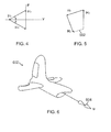
- FIG. 5 an exemplary graph providing residual momentum 502 may be shown.
- This residual momentum 502 may result from frictional losses, bias torque on the system or a number of other contributors.
- the residual momentum 502 may limit the amount of torque that may be extracted from the CMGs 102.
- the combination of vectors H 1 , H 2 and H 3 shown in Figure 5 has a non-zero residual momentum 502.
- Residual momentum 502 in the CMG array 102 may be mitigated by applying an external torque in the direction equal to and opposite to the system.
- the torque may be provided through a process referred to as desaturation.
- the residual moment 502 of the CMGs 102 may be driven to a desired momentum state by generating a command equal to the difference between the desired state and the momentum residual times some gain.
- the Law of Conservation of Angular Momentum provides that the residual momentum 502 may be determined by summing the momentum of the platform and the momentum stored in the CMGs 102. In a zero residual momentum state, the platform and CMG momentum may be equal and opposite.
- the goal of desaturization may be to drive the residual momentum 502 in the CMGs 102 to zero or within a threshold of zero.
- a bias momentum state may be created in anticipation of a specific maneuver. When a bias momentum state is generated, the amount of momentum transfer may be extended beyond that available by initiating the maneuver from a zero-bias state.
- utilizing dedicated or existing aero-control surfaces may be used to produce the torque 604 counter to the residual momentum 502 on the CMGs 102 when saturated.
- the torque 604 may be in a vectored direction that reduces the stored angular momentum in the CMGs 102.
- This airflow over the aero-control surface may produce positive torque 604 on the aircraft 602.
- airflow over the tail section may be used.
- the aero-control surfaces of the aircraft 602 may produce a roll axis torque M 604 that may cancel a CMG residual momentum 502 in that direction.
- desaturation of residual momentum 502 may no longer require dedicated surfaces or thruster mechanisms.
- the system may be used in other vehicles having CMGs 102 such as watercraft. A stream of air or liquid may be used.
- the airstream may be taken from outside the aircraft 602.
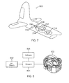
- the airstream may be captured through an air intake 702.
- More than one air intake 702 may exist on the aircraft 602.
- the intake 702 may include a scoop that receives the airstream.
- the intake 702 may project from the outer surface of the aircraft 602, which may be designed to utilize the dynamic pressure of the airstream to maintain a flow of air.
- the airstream may be taken in through an under carriage of the aircraft 602.
- the air intake 702 may re-direct air into a duct and manifold management system 704.
- the aircraft 602 may have a number of valves 706 that may receive the airstream from the duct and manifold management system 704.
- the airstream from the valves 706 may be directed in a manner that produces thrust via nozzles 708 strategically placed on the aircraft 602. The thrust may then be used to generate torque 604 to desaturate the CMGs 102.
- the system for desaturating the CMGs 102 is shown in the tail section of the aircraft 602, the system may be placed in other locations.
- the air intake 702 and duct and manifold system 704 may be provided in a middle portion of the aircraft 602 or at least a portion thereof. Portions of the desaturation system may be placed in the wings of the aircraft 602.
- the thrust may be generated from another on-board source, for example, an auxiliary power unit (APU) within the aircraft 602. Bleed thrust from an engine exhaust or a dedicated gas or liquid pressure generating device may also be used.
- APU auxiliary power unit
- Bleed thrust from an engine exhaust or a dedicated gas or liquid pressure generating device may also be used.
- the amount of desaturation torque 604 to be generated may be calculated, commanded and controlled via a processor 710 that utilizes sensor input from the aircraft 602 and CMG sensors.
- FIG 8 an exemplary block diagram providing generalized components for desaturating the CMGs 102 may be shown.
- the airstream 802 may be taken from a variety of sources. As shown above, the airstream may be taken from an external source.
- the airstream 802 may be received by a channel 804.
- the channel 804 may include the air intake 702, duct and manifold management system 704, valves 706 and nozzles 708.
- the airstream 802 may be taken from a propulsion device on the aircraft 602.
- the bleed air may be taken from a compressor of the propulsion device.
- the bleed air may then be provided to the channel 804.
- the channel 804, in this embodiment, may include fewer or more parts than that described above.
- the airstream 802 may be directed to the nozzles 708 within the channel 804 without using the air intake 702, duct and manifold management system 704 and valves 706.
- a combination of both the outside vectored air and the bleed air may be used.
- the channel 804 may have one or more nozzles 708.
- the nozzles 708 may be fixed.
- the fixed nozzles 708 may be selected to direct the airstream 802 to produce a desired torque 604 to desaturate the CMGs 102.
- the nozzles 708 may be selected based on angle and amount of torque 604 that may be generated therefrom.
- the nozzles 708 may be maneuverable. The nozzles may be moved to direct the airstream 802 and to produce the desired torque 604.
- torque 604 may be produced via a steering law or modulating the thrust from fixed nozzles 708 via a selection control law.
- the torque 604 may be generated via commanding aero-control surfaces to generate a torque in a direction opposite to that of the residual 502 and for a duration to produce an equivalent momentum thereby reducing the residual 502 to a near or zero residual state.
- software 806 may be used to vector the airstream 802.
- the software 806 may also be used for detecting saturation within the CMGs 102.
- Sensors may be attached to the CMGs 102 where saturated angular momentum within it may be detected. Saturation may be calculated based on the known orientation of the gimbal axis 106 of the CMGs 102.
- an estimation of the individual CMG momentum vectors which may be determined by knowledge of the inertial mass about its spin axis and a sensor that determines the rotational speed may be used.
- the appropriate amount of thrust may be determined within the algorithm and the nozzles 708 therein may be used to generate enough torque 604 to counteract the saturation within the CMGs 102.
- torque 604 may be provided to deplete the residual momentum through a combination of aero-control surfaces.
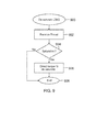
- a flow chart providing illustrative processes for desaturating the CMGs 102 may be shown.
- the processes for desaturation the CMGs 102 may begin at block 900.
- the system may receive thrust.
- the thrust as described above, may come from a variety of sources including outside the aircraft 602 through an air intake 702. Alternatively, the thrust may be bleed air received from a propulsion device.
- Saturation of the CMGs 102 may be detected at decision block 904.
- the useful torque and momentum transfer provided by the CMG 102 may be limited.
- the saturation may be detected by an algorithm or other control circuitry within the array 102 or other control processor.
- the momentum state may be calculated with an estimation of the stored angular momentum in the individual CMGs along with knowledge of their relative angular orientation through vector math/algorithms.
- the processes may end at block 908. Otherwise, the system may direct torque 604 to desaturate the CMGs 102 at block 906.
- the amount of torque 604 to desaturate the CMGs 102 may be computed by the algorithm.
- nozzles 708 may be either fixed or maneuverable by the algorithm to redirect the airflow. The processes may end at block 908.
- a method for adjusting a control moment gyroscope array 102 including: receiving a stream; and directing the stream to adjust momentum in the control moment gyroscope array 102.
- the method includes detecting saturation of the control moment gyroscope array 102.
- the method includes wherein receiving the stream comprises extracting bleed air from a propulsion device.
- the method includes wherein extracting the bleed air from the propulsion device comprises obtaining the bleed air from a compressor of the propulsion device.
- the method includes wherein directing the stream to reduce the momentum in the control moment gyroscope 102A, 102B, 102C includes maneuvering at least one nozzle 708 in a coordinated direction to produce a desired torque 604.
- the method includes wherein directing the stream to reduce the momentum in the control moment gyroscope 102A, 102B, 102C includes selecting at least one fixed nozzle 708 to produce a desired torque 604. In another alternative, the method includes wherein directing the stream to adjust the momentum in the control moment gyroscope (102A, 102B, 102C) comprises driving momentum in the control moment gyroscope (102A, 102B, 102C) to a desired state or threshold for generating a bias in large momentum maneuvers.
- a control moment gyroscope array 102 including: a plurality of control moment gyroscopes (CMGs) 102A, 102B, 102C having saturated angular momentum; and a channel receiving airflow for adjusting the angular momentum residual.
- the control moment gyroscope includes wherein the channel includes an air intake 702, duct and manifold system 704 and at least one valve and nozzle 708.
- the control moment gyroscope includes wherein the at least one nozzle 708 is maneuverable.
- the control moment gyroscope includes wherein the at least one nozzle 708 is fixed.
- control moment gyroscope including software for determining an amount of the airflow for removing the saturated angular momentum.
- control moment gyroscope includes software for determining whether a rotor 102 is saturated.
- control moment gyroscope of Claim 8 comprising a propulsion device for providing the airflow.
- a system including:
- reaction wheel arrays may be desaturated.
- Other angular momentum storage systems that combine various momentum devices may also be desaturated using those features presented above.
- the data structures and code within the software 806, in which the present disclosure may be implemented, may typically be stored on a non-transitory computer-readable storage.
- the storage may be any device or medium that may store code and/or data for use by a processor.
- the non-transitory computer-readable storage medium includes, but is not limited to, volatile memory, non-volatile memory, magnetic and optical storage devices such as disk drives, magnetic tape, CDs (compact discs), DVDs (digital versatile discs or digital video discs), or other media capable of storing code and/or data now known or later developed.
- the methods and processes described in the disclosure may be embodied as code and/or data, which may be stored in a non-transitory computer-readable storage medium as described above.
- a computer system reads and executes the code and/or data stored on the non-transitory computer-readable storage medium, the computer system performs the methods and processes embodied as data structures and code and stored within the non-transitory computer-readable storage medium.
- the methods and processes described may be included in hardware modules.
- the hardware modules may include, but are not limited to, application-specific integrated circuit (ASIC) chips, field-programmable gate arrays (FPGAs), and other programmable-logic devices now known or later developed. When the hardware modules are activated, the hardware modules perform the methods and processes included within the hardware modules.
- ASIC application-specific integrated circuit
- FPGAs field-programmable gate arrays
- the technology described herein may be implemented as logical operations and/or modules.
- the logical operations may be implemented as a sequence of processor-implemented executed steps and as interconnected machine or circuit modules.
- the descriptions of various component modules may be provided in terms of operations executed or effected by the modules.
- the resulting implementation is a matter of choice, dependent on the performance requirements of the underlying system implementing the described technology. Accordingly, the logical operations making up the embodiment of the technology described herein are referred to variously as operations, steps, objects, or modules. It should be understood that logical operations may be performed in any order, unless explicitly claimed otherwise or a specific order is inherently necessitated by the claim language.
Landscapes
- Engineering & Computer Science (AREA)
- Remote Sensing (AREA)
- Radar, Positioning & Navigation (AREA)
- Aviation & Aerospace Engineering (AREA)
- Physics & Mathematics (AREA)
- General Physics & Mathematics (AREA)
- Chemical & Material Sciences (AREA)
- Combustion & Propulsion (AREA)
- Manufacturing & Machinery (AREA)
- Control Of Position, Course, Altitude, Or Attitude Of Moving Bodies (AREA)
- Feedback Control In General (AREA)
- Gyroscopes (AREA)
Abstract
Description
- Embodiments of this disclosure generally relate to a control moment gyroscope (CMG), and more particularly, to managing momentum in CMGs using vectored air and/or bleed exhaust from a propulsion system.
- CMGs may be commonly employed in aircraft systems for controlling attitude. A generalized CMG may include a housing that supports an inner gimbal assembly (IGA). The IGA may include a rotor having an inertial element, for example, a rotating ring or cylinder coupled to a shaft. Spin bearings may be disposed around the shaft ends to facilitate the rotational movement of the shaft, which may be rotated about a spin axis by a spin motor.
- The IGA, in turn, may be rotated about a gimbal axis by a torque module assembly (TMA) mounted to a first end of the CMG housing. To facilitate the rotational movement of the IGA, gimbal bearings may be disposed between the IGA and the CMG housing. A sensor module assembly (SMA) may also be mounted to a second portion of the CMG housing opposite the TMA to deliver electrical signals and power to the IGA. The CMG may include a number of sensors suitable for determining rotational rate and position of the IGA.
- A CMG may include a spinning rotor and one or more motorized gimbals that tilt the rotor's angular momentum. A plurality of CMGs may be arranged to form an array. Control of the CMGs in the array may be performed individually or in concert as part of a momentum management system.
- Losses and external disturbances may saturate the momentum in a CMG array. The saturated moment may result in loss of effectiveness of the CMG for control that may prevent desired attitude. By desaturating, the CMG momentum may be brought back into nominal values and function properly.
- Therefore, it would be desirable to provide a system and method for desaturating CMGs in aircraft.
- A method for adjusting a control moment gyroscope array on board an aircraft includes receiving a stream and directing the stream to reduce momentum in the control moment gyroscope.
- A control moment gyroscope array has saturated angular momentum and a channel receiving airflow for removing the saturated angular momentum.
- A system has a control moment gyroscope array and at least one channel vectoring thrust to act on the control moment gyroscope array for desaturating angular momentum.
- The features, functions, and advantages may be achieved independently in various embodiments of the disclosure or may be combined in yet other embodiments.
- Embodiments of the disclosure will become more fully understood from the detailed description and the accompanying drawings, wherein:
-
Figure 1 is an array of exemplary control moment gyroscopes (CMGs); -
Figure 2 is a number of illustrative planes formed by rotating the CMGs; -
Figure 3 is an exemplary graph providing momentum vectors of the CMGs; -
Figure 4 is an exemplary graph providing vector sums in a zero momentum state; -
Figure 5 is an exemplary graph providing residual momentum that is non-zero; -
Figure 6 is an illustrative system for mitigating residual momentum in CMGs; -
Figure 7 is an illustrative system for desaturating the CMGs through an airstream; -
Figure 8 is an exemplary block diagram providing generalized components for desaturating the CMGs; and -
Figure 9 is a flow chart providing illustrative processes for desaturating the CMGs. - Control moment gyroscopes (CMGs) may be used for many applications including platform stabilization and vibration control of machinery. CMGs may be commonly used in transportation systems such as spacecraft, aircraft or watercraft. As part of their use, losses and periodic disturbances may result in momentum buildup in spacecraft for which magnetic torque rods or jets are used for desaturation. External disturbances may give rise to the accumulation of residual momentum. The residual momentum may build up to a point where the CMG array becomes saturated. When saturated, the useful torque and momentum transfer provided by the CMGs may be limited.
- Typically, at least three CMGs may be used to perform three-axis stabilization as CMG momentum may be constrained to an aircraft. In one embodiment, two CMGs in a scissor-pair arrangement to control torque and momentum in one axis may be used. Referring to
Figure 1 , an array ofexemplary CMGs CMGs 102 may be in a box configuration with their momentum vectors oriented in a nominal +Z direction. EachCMG 102 may include an inner gimbal assembly (IGA) 104A, 104B and 104C (collectively 104) that has a rotational degree of freedom about itsgimbal axis - The IGAs 104 may contain a rotating inertial mass (rotor) that may store angular momentum. This
rotor 102 may be suspended in a rotating mount. The angular momentum vectors H1, H2 and H3 of the IGAs 104 may be processed about their gimbal axis 106 thereby creating control torque. H1 may be associated with CMG 102A, H2 may be associated withCMG 102B and H3 may be associated withCMG 102C. Gimbal actuation may be accomplished using a mechanism often called a torque module assembly (TMA) 108A, 108B and 108C (collectively 108). Each momentum vector H1, H2 and H3 may be oriented in a plane formed by the rotation about each gimbal axis 106. - While
multiple CMGs 102 have been shown, other configurations may exist. CMGs 102 may be single or multiple gimbaled devices. Applications requiring significant levels of torque may tend to have a single-gimbal in order to take advantage of what is often referred to as "torque multiplication". Double gimbal devices may be used where low torque, high momentum may be required. Furthermore fewer ormore CMGs 102 may be used that do not have to be constrained to a plane. - In
Figure 2 , a number ofillustrative planes CMGs 102 depicted inFigure 1 may be shown. The momentum vector H1 ofCMG 102A may be provided inplane 202A. The momentum vector H2 ofCMG 102B may be provided inplane 202B, while the momentum vector H3 ofCMG 102C may be provided inplane 202C. The three planes 202 may form abox configuration 200. - In one embodiment, the momentum vectors H1, H2 and H3 may be oriented such that the net momentum for the
CMGs 102 may be zero. Turning toFigure 3 , an exemplary graph providing momentum vectors H1, H2 and H3 of theCMGs 102 may be shown. H1 and H2 may have momentum vectors angled at thirty degrees that may cancel their Y-axis components along with the vertical component of H3 along the Z-axis.Figure 4 may show how the momentum vectors H1, H2 and H3 sum to a zero momentum state. - When saturated, the momentum is non-zero which may make the
CMGs 102 loose effectiveness and control. When anarray 102 is completely saturated, there is no amount of momentum that may be extracted in that particular direction (in the saturated direction). In one embodiment, "saturated" may describe when the momentum is above a threshold, but may be interchangeable with completely saturated. Utilization of CMG momentum in attitude control may include creating torque by rotating the individual CMG momentum vectors. That torque may be reacted by the host structure that in turn rotates. The relative rotation of the host structure may tend to balance the momentum in theCMG array 102. In other words, the host platform may rotate with momentum equal to and opposite that of theCMG array 102. In a condition where the host platform is at rest and the momentum of theCMG array 102 is non-zero, the residual may act to mitigate the amount of torque and momentum that may be used to control the angular attitude and rate of the host structure. Management of that momentum residual may be used to have effective attitude control so desaturation may be utilized. In rare cases, an operator or system may elect to create a bias momentum vector prior to a large momentum maneuver in order to extend the amount utilized in a maneuver, later to be desaturated towards a nominal, zero momentum state. The same methods may be utilized to desaturate aCMG array 102 and may be used to build up a momentum bias in anticipation of such a maneuver. - In
Figure 5 , an exemplary graph providingresidual momentum 502 may be shown. Thisresidual momentum 502 may result from frictional losses, bias torque on the system or a number of other contributors. Ultimately, theresidual momentum 502 may limit the amount of torque that may be extracted from theCMGs 102. - The combination of vectors H1, H2 and H3 shown in
Figure 5 has a non-zeroresidual momentum 502.Residual momentum 502 in theCMG array 102 may be mitigated by applying an external torque in the direction equal to and opposite to the system. The torque may be provided through a process referred to as desaturation. Theresidual moment 502 of theCMGs 102 may be driven to a desired momentum state by generating a command equal to the difference between the desired state and the momentum residual times some gain. The Law of Conservation of Angular Momentum provides that theresidual momentum 502 may be determined by summing the momentum of the platform and the momentum stored in theCMGs 102. In a zero residual momentum state, the platform and CMG momentum may be equal and opposite. The goal of desaturization may be to drive theresidual momentum 502 in theCMGs 102 to zero or within a threshold of zero. A bias momentum state may be created in anticipation of a specific maneuver. When a bias momentum state is generated, the amount of momentum transfer may be extended beyond that available by initiating the maneuver from a zero-bias state. - In an
aircraft 602, as provided inFigure 6 , utilizing dedicated or existing aero-control surfaces may be used to produce thetorque 604 counter to theresidual momentum 502 on theCMGs 102 when saturated. Thetorque 604 may be in a vectored direction that reduces the stored angular momentum in theCMGs 102. This airflow over the aero-control surface may producepositive torque 604 on theaircraft 602. In one embodiment, airflow over the tail section may be used. - As depicted, the aero-control surfaces of the
aircraft 602 may produce a rollaxis torque M 604 that may cancel a CMGresidual momentum 502 in that direction. By utilizing existing sources of thrust from anaircraft 602, desaturation ofresidual momentum 502 may no longer require dedicated surfaces or thruster mechanisms. The system may be used in othervehicles having CMGs 102 such as watercraft. A stream of air or liquid may be used. - Turning to
Figure 7 , an illustrative system for desaturating theCMGs 102 through an airstream may be shown. The airstream may be taken from outside theaircraft 602. In the shown embodiment, the airstream may be captured through anair intake 702. More than oneair intake 702 may exist on theaircraft 602. Theintake 702 may include a scoop that receives the airstream. Theintake 702 may project from the outer surface of theaircraft 602, which may be designed to utilize the dynamic pressure of the airstream to maintain a flow of air. The airstream may be taken in through an under carriage of theaircraft 602. - The
air intake 702 may re-direct air into a duct andmanifold management system 704. Theaircraft 602 may have a number ofvalves 706 that may receive the airstream from the duct andmanifold management system 704. The airstream from thevalves 706 may be directed in a manner that produces thrust vianozzles 708 strategically placed on theaircraft 602. The thrust may then be used to generatetorque 604 to desaturate theCMGs 102. - While the system for desaturating the
CMGs 102 is shown in the tail section of theaircraft 602, the system may be placed in other locations. For example, theair intake 702 and duct andmanifold system 704 may be provided in a middle portion of theaircraft 602 or at least a portion thereof. Portions of the desaturation system may be placed in the wings of theaircraft 602. - In one embodiment, the thrust may be generated from another on-board source, for example, an auxiliary power unit (APU) within the
aircraft 602. Bleed thrust from an engine exhaust or a dedicated gas or liquid pressure generating device may also be used. The amount ofdesaturation torque 604 to be generated may be calculated, commanded and controlled via aprocessor 710 that utilizes sensor input from theaircraft 602 and CMG sensors. - In
Figure 8 , an exemplary block diagram providing generalized components for desaturating theCMGs 102 may be shown. Theairstream 802 may be taken from a variety of sources. As shown above, the airstream may be taken from an external source. Theairstream 802 may be received by achannel 804. Thechannel 804 may include theair intake 702, duct andmanifold management system 704,valves 706 andnozzles 708. - As also shown, the
airstream 802 may be taken from a propulsion device on theaircraft 602. The bleed air may be taken from a compressor of the propulsion device. The bleed air may then be provided to thechannel 804. Thechannel 804, in this embodiment, may include fewer or more parts than that described above. For example, theairstream 802 may be directed to thenozzles 708 within thechannel 804 without using theair intake 702, duct andmanifold management system 704 andvalves 706. In one embodiment, a combination of both the outside vectored air and the bleed air may be used. - In each, the
channel 804 may have one ormore nozzles 708. Thenozzles 708 may be fixed. The fixednozzles 708 may be selected to direct theairstream 802 to produce a desiredtorque 604 to desaturate theCMGs 102. For example, thenozzles 708 may be selected based on angle and amount oftorque 604 that may be generated therefrom. Alternatively, thenozzles 708 may be maneuverable. The nozzles may be moved to direct theairstream 802 and to produce the desiredtorque 604. - By gimbaling the
nozzles 708 within thechannel 804 in a coordinated set of directions,torque 604 may be produced via a steering law or modulating the thrust from fixednozzles 708 via a selection control law. Similarly, thetorque 604 may be generated via commanding aero-control surfaces to generate a torque in a direction opposite to that of the residual 502 and for a duration to produce an equivalent momentum thereby reducing the residual 502 to a near or zero residual state. - In both the fixed and
maneuverable nozzles 708,software 806 may be used to vector theairstream 802. Thesoftware 806 may also be used for detecting saturation within theCMGs 102. Sensors may be attached to theCMGs 102 where saturated angular momentum within it may be detected. Saturation may be calculated based on the known orientation of the gimbal axis 106 of theCMGs 102. In addition to a gimbal angle, an estimation of the individual CMG momentum vectors which may be determined by knowledge of the inertial mass about its spin axis and a sensor that determines the rotational speed may be used. - The appropriate amount of thrust may be determined within the algorithm and the
nozzles 708 therein may be used to generateenough torque 604 to counteract the saturation within theCMGs 102. Through thechannel 804,torque 604 may be provided to deplete the residual momentum through a combination of aero-control surfaces. - Referring to
Figure 9 , a flow chart providing illustrative processes for desaturating theCMGs 102 may be shown. The processes for desaturation theCMGs 102 may begin atblock 900. Atblock 902, the system may receive thrust. The thrust, as described above, may come from a variety of sources including outside theaircraft 602 through anair intake 702. Alternatively, the thrust may be bleed air received from a propulsion device. - Saturation of the
CMGs 102 may be detected atdecision block 904. When saturated, or above the threshold where desaturation is desired, the useful torque and momentum transfer provided by theCMG 102 may be limited. The saturation may be detected by an algorithm or other control circuitry within thearray 102 or other control processor. The momentum state may be calculated with an estimation of the stored angular momentum in the individual CMGs along with knowledge of their relative angular orientation through vector math/algorithms. When no saturation has been detected, the processes may end atblock 908. Otherwise, the system may directtorque 604 to desaturate theCMGs 102 atblock 906. The amount oftorque 604 to desaturate theCMGs 102 may be computed by the algorithm. Furthermore,nozzles 708 may be either fixed or maneuverable by the algorithm to redirect the airflow. The processes may end atblock 908. - In the text and the figures, a method is disclosed for adjusting a control
moment gyroscope array 102 including: receiving a stream; and directing the stream to adjust momentum in the controlmoment gyroscope array 102. In one variant, the method includes detecting saturation of the controlmoment gyroscope array 102. In another variant, the method includes wherein receiving the stream comprises extracting bleed air from a propulsion device. In one instance, the method includes wherein extracting the bleed air from the propulsion device comprises obtaining the bleed air from a compressor of the propulsion device. In one example, the method includes wherein directing the stream to reduce the momentum in thecontrol moment gyroscope nozzle 708 in a coordinated direction to produce a desiredtorque 604. - In one alternative, the method includes wherein directing the stream to reduce the momentum in the
control moment gyroscope fixed nozzle 708 to produce a desiredtorque 604. In another alternative, the method includes wherein directing the stream to adjust the momentum in the control moment gyroscope (102A, 102B, 102C) comprises driving momentum in the control moment gyroscope (102A, 102B, 102C) to a desired state or threshold for generating a bias in large momentum maneuvers. - In one aspect, a control
moment gyroscope array 102 is disclosed including: a plurality of control moment gyroscopes (CMGs) 102A, 102B, 102C having saturated angular momentum; and
a channel receiving airflow for adjusting the angular momentum residual. In one variant, the control moment gyroscope includes wherein the channel includes anair intake 702, duct andmanifold system 704 and at least one valve andnozzle 708. Inone variant, the control moment gyroscope includes wherein the at least onenozzle 708 is maneuverable. In one variant, the control moment gyroscope includes wherein the at least onenozzle 708 is fixed. In another variant, the control moment gyroscope is disclosed including software for determining an amount of the airflow for removing the saturated angular momentum. In still another variant, the control moment gyroscope includes software for determining whether arotor 102 is saturated. In yet another variant, the control moment gyroscope of Claim 8, comprising a propulsion device for providing the airflow. - In another aspect, a system is disclosed including:
- a control
moment gyroscope array 102; and at least one channel vectoring thrust to the controlmoment gyroscope array 102 for adjusting angular momentum. In one variant, the system of Claim 15, comprising a propulsion system for providing the thrust. In one variant, the system includes an air intake (702) for providing the thrust. In one variant, the system includes wherein the thrust comprises bleed air and other vectored air. In another variant, the system includes wherein adjusting the angular momentum comprises desaturating or adjusting to a desired momentum state. In yet another variant, the system of includes aero-control surfaces combined with the thrust for adjusting the angular momentum. - The features presented herein may be extended to other technologies. For example, the system may be converted such that reaction wheel arrays may be desaturated. Other angular momentum storage systems that combine various momentum devices may also be desaturated using those features presented above.
- The data structures and code within the
software 806, in which the present disclosure may be implemented, may typically be stored on a non-transitory computer-readable storage. The storage may be any device or medium that may store code and/or data for use by a processor. The non-transitory computer-readable storage medium includes, but is not limited to, volatile memory, non-volatile memory, magnetic and optical storage devices such as disk drives, magnetic tape, CDs (compact discs), DVDs (digital versatile discs or digital video discs), or other media capable of storing code and/or data now known or later developed. - The methods and processes described in the disclosure may be embodied as code and/or data, which may be stored in a non-transitory computer-readable storage medium as described above. When a computer system reads and executes the code and/or data stored on the non-transitory computer-readable storage medium, the computer system performs the methods and processes embodied as data structures and code and stored within the non-transitory computer-readable storage medium. Furthermore, the methods and processes described may be included in hardware modules. For example, the hardware modules may include, but are not limited to, application-specific integrated circuit (ASIC) chips, field-programmable gate arrays (FPGAs), and other programmable-logic devices now known or later developed. When the hardware modules are activated, the hardware modules perform the methods and processes included within the hardware modules.
- The technology described herein may be implemented as logical operations and/or modules. The logical operations may be implemented as a sequence of processor-implemented executed steps and as interconnected machine or circuit modules. Likewise, the descriptions of various component modules may be provided in terms of operations executed or effected by the modules. The resulting implementation is a matter of choice, dependent on the performance requirements of the underlying system implementing the described technology. Accordingly, the logical operations making up the embodiment of the technology described herein are referred to variously as operations, steps, objects, or modules. It should be understood that logical operations may be performed in any order, unless explicitly claimed otherwise or a specific order is inherently necessitated by the claim language.
- While embodiments of the disclosure have been described in terms of various specific embodiments, those skilled in the art will recognize that the embodiments of the disclosure may be practiced with modifications within the spirit and scope of the claims.
Claims (15)
- A method for adjusting a control moment gyroscope array (102) comprising:receiving a stream; anddirecting the stream to adjust momentum in the control moment gyroscope array (102).
- The method of Claim 1, comprising detecting saturation of the control moment gyroscope array (102).
- The method of any of Claims 1 or 2, wherein receiving the stream comprises extracting bleed air from a propulsion device.
- The method of Claim 3, wherein extracting the bleed air from the propulsion device comprises obtaining the bleed air from a compressor of the propulsion device.
- The method of any of Claims 1-4, wherein directing the stream to reduce the momentum in the control moment gyroscope (102A, 102B, 102C) comprises maneuvering at least one nozzle (708) in a coordinated direction to produce a desired torque (604).
- The method of any of Claims 1-4, wherein directing the stream to reduce the momentum in the control moment gyroscope (102A, 102B, 102C) comprises selecting at least one fixed nozzle (708) to produce a desired torque (604).
- The method of any of Claims 1-4, wherein directing the stream to adjust the momentum in the control moment gyroscope (102A, 102B, 102C) comprises driving momentum in the control moment gyroscope (102A, 102B, 102C) to a desired state or threshold for generating a bias in large momentum maneuvers.
- A control moment gyroscope array (102) comprising:a plurality of control moment gyroscopes (CMGs) (102A, 102B, 102C) having saturated angular momentum; anda channel receiving airflow for adjusting the angular momentum residual.
- The control moment gyroscope of Claim 8, wherein the channel comprises an air intake(702), duct and manifold system (704) and at least one valve and nozzle (708).
- The control moment gyroscope of Claim 9, wherein the at least one nozzle (708) is maneuverable.
- The control moment gyroscope of Claim 9, wherein the at least one nozzle (708) is fixed.
- The control moment gyroscope of any of Claims 8-11, comprising software for determining an amount of the airflow for removing the saturated angular momentum.
- The control moment gyroscope of any of Claim 8-11, comprising software for determining whether a rotor (102) is saturated.
- The control moment gyroscope of any of Claims 8-13, comprising a propulsion device for providing the airflow.
- The control moment gyroscope array as recited in any of the Claims 8-14 adjusted by the method as recited in of any of the Claims 1-7.
Applications Claiming Priority (1)
| Application Number | Priority Date | Filing Date | Title |
|---|---|---|---|
| US13/305,922 US20130133445A1 (en) | 2011-11-29 | 2011-11-29 | Control moment gyroscope desaturation in aircraft |
Publications (2)
| Publication Number | Publication Date |
|---|---|
| EP2599716A1 true EP2599716A1 (en) | 2013-06-05 |
| EP2599716B1 EP2599716B1 (en) | 2019-04-10 |
Family
ID=47227702
Family Applications (1)
| Application Number | Title | Priority Date | Filing Date |
|---|---|---|---|
| EP12194894.7A Active EP2599716B1 (en) | 2011-11-29 | 2012-11-29 | Control moment gyroscope desaturation in aircraft |
Country Status (4)
| Country | Link |
|---|---|
| US (1) | US20130133445A1 (en) |
| EP (1) | EP2599716B1 (en) |
| CN (1) | CN103135543A (en) |
| ES (1) | ES2733933T3 (en) |
Families Citing this family (4)
| Publication number | Priority date | Publication date | Assignee | Title |
|---|---|---|---|---|
| WO2017116705A1 (en) * | 2015-12-31 | 2017-07-06 | Sikorsky Aircraft Corporation | Vibration control assembly |
| CN109388145B (en) * | 2017-08-07 | 2020-08-21 | 深圳市道通智能航空技术有限公司 | Method and device for controlling aircraft and aircraft |
| CN113156987B (en) * | 2021-04-15 | 2022-05-31 | 哈尔滨工业大学 | Spacecraft actuating mechanism combining double-frame shear type moment gyroscope and flywheel and control method thereof |
| CN113720355B (en) * | 2021-09-10 | 2023-11-10 | 北京控制工程研究所 | A method and system for autonomous diagnosis of gyro output saturation |
Citations (3)
| Publication number | Priority date | Publication date | Assignee | Title |
|---|---|---|---|---|
| US20020145077A1 (en) * | 2001-04-05 | 2002-10-10 | Northrop Grumman Corporation. | Method and system for directing an object |
| US20110153123A1 (en) * | 2009-12-22 | 2011-06-23 | The Boeing Company | Algorithm for simultaneous attitude maneuver and momentum dumping |
| US20110309191A1 (en) * | 2010-06-17 | 2011-12-22 | Lockheed Martin Corporation | System and Method For Desaturation of a Control Moment Gyroscope |
Family Cites Families (14)
| Publication number | Priority date | Publication date | Assignee | Title |
|---|---|---|---|---|
| US2973162A (en) * | 1959-02-12 | 1961-02-28 | Haeussermann Walter | Attitude control system for space vehicles |
| US4726545A (en) * | 1986-12-02 | 1988-02-23 | Grumman Aerospace Corporation | VTOL aircraft having combination lift and lift/cruise engines |
| US4919367A (en) * | 1988-02-29 | 1990-04-24 | Whitcomb Melville T | Satellite attitude control |
| US4960250A (en) * | 1988-09-12 | 1990-10-02 | Space Industries Partnership, L.P. | Energy desaturation of electromechanical actuators used in satellite attitude control |
| FR2670745B1 (en) * | 1990-12-21 | 1993-04-16 | Aerospatiale | ATTITUDE CONTROL SYSTEM FOR 3-AXIS STABILIZED SATELLITE ON LOW TILT ORBIT. |
| US5131605A (en) * | 1991-06-12 | 1992-07-21 | Grumman Aerospace Corporation | Four engine VTOL aircraft |
| US6119985A (en) * | 1997-03-07 | 2000-09-19 | Pioneer Rocketplane Corporation | Reusable rocket-propelled high altitude airplane and method and apparatus for mid-air oxidizer transfer to said airplane |
| US6311931B1 (en) * | 1999-12-17 | 2001-11-06 | The Boeing Company | Bi-directional momentum bias spacecraft attitude control |
| US6622962B1 (en) * | 2002-04-29 | 2003-09-23 | Bruce D. White | Fixed wing aircraft having powered rotor VTOL capability with rotor blades stowable during horizontal flight |
| JP3970724B2 (en) * | 2002-08-30 | 2007-09-05 | Nec東芝スペースシステム株式会社 | Attitude change control device and attitude change control method for flying object |
| US8019493B1 (en) * | 2007-07-20 | 2011-09-13 | Lockheed Martin Corporation | Spacecraft thruster torque feedforward calibration system |
| GB0909158D0 (en) * | 2009-05-29 | 2009-07-08 | Rolls Royce Plc | An aircraft having a lift/propulsion unit |
| US20110011982A1 (en) * | 2009-07-20 | 2011-01-20 | Jason Herman | Modular control moment gyroscope (cmg) system for spacecraft attitude control |
| US8880246B1 (en) * | 2012-08-22 | 2014-11-04 | United States Of America As Represented By The Secretary Of The Navy | Method and apparatus for determining spacecraft maneuvers |
-
2011
- 2011-11-29 US US13/305,922 patent/US20130133445A1/en not_active Abandoned
-
2012
- 2012-11-26 CN CN2012104876862A patent/CN103135543A/en active Pending
- 2012-11-29 ES ES12194894T patent/ES2733933T3/en active Active
- 2012-11-29 EP EP12194894.7A patent/EP2599716B1/en active Active
Patent Citations (3)
| Publication number | Priority date | Publication date | Assignee | Title |
|---|---|---|---|---|
| US20020145077A1 (en) * | 2001-04-05 | 2002-10-10 | Northrop Grumman Corporation. | Method and system for directing an object |
| US20110153123A1 (en) * | 2009-12-22 | 2011-06-23 | The Boeing Company | Algorithm for simultaneous attitude maneuver and momentum dumping |
| US20110309191A1 (en) * | 2010-06-17 | 2011-12-22 | Lockheed Martin Corporation | System and Method For Desaturation of a Control Moment Gyroscope |
Also Published As
| Publication number | Publication date |
|---|---|
| ES2733933T3 (en) | 2019-12-03 |
| EP2599716B1 (en) | 2019-04-10 |
| US20130133445A1 (en) | 2013-05-30 |
| CN103135543A (en) | 2013-06-05 |
Similar Documents
| Publication | Publication Date | Title |
|---|---|---|
| US10805540B2 (en) | Quadcopter with pitched propeller configuration | |
| KR102941356B1 (en) | Bidirectional thrust device, system, and method | |
| US8763957B1 (en) | Spacecraft transfer orbit techniques | |
| JP2019189217A (en) | Pitch and thrust control for compound aircraft | |
| EP2599716B1 (en) | Control moment gyroscope desaturation in aircraft | |
| EP2336022A2 (en) | Morphing ducted fan for vertical take-off and landing vehicle | |
| JP2019503941A (en) | Vertical take-off and landing aircraft and its operation process | |
| US9334068B2 (en) | Unified orbit and attitude control for nanosatellites using pulsed ablative thrusters | |
| US8561944B2 (en) | System and method for desaturation of a control moment gyroscope | |
| CN106697331A (en) | Energy efficient satellite maneuvering | |
| US12560942B2 (en) | Thrust vectoring for fluid borne vehicles | |
| US7264202B2 (en) | Tri-cycloidal airship | |
| JP2013500459A (en) | Method and apparatus for a tandem turning and attitude control system | |
| JP2018144732A (en) | Flight equipment | |
| Defendini et al. | Low cost CMG-based AOCS designs | |
| Sawada et al. | High-stability attitude control of satellites by magnetic bearing wheels | |
| GB2461051A (en) | VTOL aircraft control | |
| JP7106006B2 (en) | Debris collection control device, debris collection satellite, capture interface device, connection device, debris collection system, debris collection method, and debris collection program | |
| US9617015B2 (en) | Method of commanding an attitude control system and attitude control system of a space vehicle | |
| FR2809502A1 (en) | Orientation control method for a low-orbit satellite using a triaxial arrangement of magneto-couplers together with a triaxial magnetometer for ensuring the satellite is correctly aligned using the Earth's magnetic field | |
| Sasaki et al. | Adaptive control/steering design for deorbiting space debris with hybrid actuators configuration | |
| CN118289229A (en) | Satellite control method, system, computer device and storage medium | |
| JP4930072B2 (en) | Satellite attitude control device | |
| Hall et al. | Ares i flight control system overview | |
| Terzibaschian et al. | High torque wheels for agile satellite maneuvers-in orbit experiences and future steps with recuperation of energy |
Legal Events
| Date | Code | Title | Description |
|---|---|---|---|
| PUAI | Public reference made under article 153(3) epc to a published international application that has entered the european phase |
Free format text: ORIGINAL CODE: 0009012 |
|
| 17P | Request for examination filed |
Effective date: 20121129 |
|
| AK | Designated contracting states |
Kind code of ref document: A1 Designated state(s): AL AT BE BG CH CY CZ DE DK EE ES FI FR GB GR HR HU IE IS IT LI LT LU LV MC MK MT NL NO PL PT RO RS SE SI SK SM TR |
|
| AX | Request for extension of the european patent |
Extension state: BA ME |
|
| STAA | Information on the status of an ep patent application or granted ep patent |
Free format text: STATUS: EXAMINATION IS IN PROGRESS |
|
| 17Q | First examination report despatched |
Effective date: 20180129 |
|
| STAA | Information on the status of an ep patent application or granted ep patent |
Free format text: STATUS: REQUEST FOR EXAMINATION WAS MADE |
|
| REG | Reference to a national code |
Ref country code: DE Ref legal event code: R079 Ref document number: 602012058774 Country of ref document: DE Free format text: PREVIOUS MAIN CLASS: B64C0017060000 Ipc: G01C0025000000 |
|
| RIC1 | Information provided on ipc code assigned before grant |
Ipc: G01C 19/02 20060101ALI20180509BHEP Ipc: G01C 25/00 20060101AFI20180509BHEP |
|
| GRAP | Despatch of communication of intention to grant a patent |
Free format text: ORIGINAL CODE: EPIDOSNIGR1 |
|
| STAA | Information on the status of an ep patent application or granted ep patent |
Free format text: STATUS: GRANT OF PATENT IS INTENDED |
|
| INTG | Intention to grant announced |
Effective date: 20180706 |
|
| GRAJ | Information related to disapproval of communication of intention to grant by the applicant or resumption of examination proceedings by the epo deleted |
Free format text: ORIGINAL CODE: EPIDOSDIGR1 |
|
| STAA | Information on the status of an ep patent application or granted ep patent |
Free format text: STATUS: REQUEST FOR EXAMINATION WAS MADE |
|
| INTC | Intention to grant announced (deleted) | ||
| GRAP | Despatch of communication of intention to grant a patent |
Free format text: ORIGINAL CODE: EPIDOSNIGR1 |
|
| STAA | Information on the status of an ep patent application or granted ep patent |
Free format text: STATUS: GRANT OF PATENT IS INTENDED |
|
| GRAJ | Information related to disapproval of communication of intention to grant by the applicant or resumption of examination proceedings by the epo deleted |
Free format text: ORIGINAL CODE: EPIDOSDIGR1 |
|
| STAA | Information on the status of an ep patent application or granted ep patent |
Free format text: STATUS: REQUEST FOR EXAMINATION WAS MADE |
|
| GRAP | Despatch of communication of intention to grant a patent |
Free format text: ORIGINAL CODE: EPIDOSNIGR1 |
|
| STAA | Information on the status of an ep patent application or granted ep patent |
Free format text: STATUS: GRANT OF PATENT IS INTENDED |
|
| INTG | Intention to grant announced |
Effective date: 20181019 |
|
| INTG | Intention to grant announced |
Effective date: 20181019 |
|
| INTG | Intention to grant announced |
Effective date: 20181102 |
|
| GRAS | Grant fee paid |
Free format text: ORIGINAL CODE: EPIDOSNIGR3 |
|
| GRAA | (expected) grant |
Free format text: ORIGINAL CODE: 0009210 |
|
| STAA | Information on the status of an ep patent application or granted ep patent |
Free format text: STATUS: THE PATENT HAS BEEN GRANTED |
|
| AK | Designated contracting states |
Kind code of ref document: B1 Designated state(s): AL AT BE BG CH CY CZ DE DK EE ES FI FR GB GR HR HU IE IS IT LI LT LU LV MC MK MT NL NO PL PT RO RS SE SI SK SM TR |
|
| REG | Reference to a national code |
Ref country code: GB Ref legal event code: FG4D |
|
| REG | Reference to a national code |
Ref country code: CH Ref legal event code: EP Ref country code: AT Ref legal event code: REF Ref document number: 1119305 Country of ref document: AT Kind code of ref document: T Effective date: 20190415 |
|
| REG | Reference to a national code |
Ref country code: IE Ref legal event code: FG4D |
|
| REG | Reference to a national code |
Ref country code: DE Ref legal event code: R096 Ref document number: 602012058774 Country of ref document: DE |
|
| REG | Reference to a national code |
Ref country code: NL Ref legal event code: MP Effective date: 20190410 |
|
| REG | Reference to a national code |
Ref country code: LT Ref legal event code: MG4D |
|
| REG | Reference to a national code |
Ref country code: AT Ref legal event code: MK05 Ref document number: 1119305 Country of ref document: AT Kind code of ref document: T Effective date: 20190410 |
|
| PG25 | Lapsed in a contracting state [announced via postgrant information from national office to epo] |
Ref country code: NL Free format text: LAPSE BECAUSE OF FAILURE TO SUBMIT A TRANSLATION OF THE DESCRIPTION OR TO PAY THE FEE WITHIN THE PRESCRIBED TIME-LIMIT Effective date: 20190410 |
|
| PG25 | Lapsed in a contracting state [announced via postgrant information from national office to epo] |
Ref country code: SE Free format text: LAPSE BECAUSE OF FAILURE TO SUBMIT A TRANSLATION OF THE DESCRIPTION OR TO PAY THE FEE WITHIN THE PRESCRIBED TIME-LIMIT Effective date: 20190410 Ref country code: LT Free format text: LAPSE BECAUSE OF FAILURE TO SUBMIT A TRANSLATION OF THE DESCRIPTION OR TO PAY THE FEE WITHIN THE PRESCRIBED TIME-LIMIT Effective date: 20190410 Ref country code: NO Free format text: LAPSE BECAUSE OF FAILURE TO SUBMIT A TRANSLATION OF THE DESCRIPTION OR TO PAY THE FEE WITHIN THE PRESCRIBED TIME-LIMIT Effective date: 20190710 Ref country code: AL Free format text: LAPSE BECAUSE OF FAILURE TO SUBMIT A TRANSLATION OF THE DESCRIPTION OR TO PAY THE FEE WITHIN THE PRESCRIBED TIME-LIMIT Effective date: 20190410 Ref country code: PT Free format text: LAPSE BECAUSE OF FAILURE TO SUBMIT A TRANSLATION OF THE DESCRIPTION OR TO PAY THE FEE WITHIN THE PRESCRIBED TIME-LIMIT Effective date: 20190910 Ref country code: HR Free format text: LAPSE BECAUSE OF FAILURE TO SUBMIT A TRANSLATION OF THE DESCRIPTION OR TO PAY THE FEE WITHIN THE PRESCRIBED TIME-LIMIT Effective date: 20190410 Ref country code: FI Free format text: LAPSE BECAUSE OF FAILURE TO SUBMIT A TRANSLATION OF THE DESCRIPTION OR TO PAY THE FEE WITHIN THE PRESCRIBED TIME-LIMIT Effective date: 20190410 |
|
| PG25 | Lapsed in a contracting state [announced via postgrant information from national office to epo] |
Ref country code: BG Free format text: LAPSE BECAUSE OF FAILURE TO SUBMIT A TRANSLATION OF THE DESCRIPTION OR TO PAY THE FEE WITHIN THE PRESCRIBED TIME-LIMIT Effective date: 20190710 Ref country code: GR Free format text: LAPSE BECAUSE OF FAILURE TO SUBMIT A TRANSLATION OF THE DESCRIPTION OR TO PAY THE FEE WITHIN THE PRESCRIBED TIME-LIMIT Effective date: 20190711 Ref country code: RS Free format text: LAPSE BECAUSE OF FAILURE TO SUBMIT A TRANSLATION OF THE DESCRIPTION OR TO PAY THE FEE WITHIN THE PRESCRIBED TIME-LIMIT Effective date: 20190410 Ref country code: LV Free format text: LAPSE BECAUSE OF FAILURE TO SUBMIT A TRANSLATION OF THE DESCRIPTION OR TO PAY THE FEE WITHIN THE PRESCRIBED TIME-LIMIT Effective date: 20190410 Ref country code: PL Free format text: LAPSE BECAUSE OF FAILURE TO SUBMIT A TRANSLATION OF THE DESCRIPTION OR TO PAY THE FEE WITHIN THE PRESCRIBED TIME-LIMIT Effective date: 20190410 |
|
| REG | Reference to a national code |
Ref country code: ES Ref legal event code: FG2A Ref document number: 2733933 Country of ref document: ES Kind code of ref document: T3 Effective date: 20191203 |
|
| PG25 | Lapsed in a contracting state [announced via postgrant information from national office to epo] |
Ref country code: IS Free format text: LAPSE BECAUSE OF FAILURE TO SUBMIT A TRANSLATION OF THE DESCRIPTION OR TO PAY THE FEE WITHIN THE PRESCRIBED TIME-LIMIT Effective date: 20190810 Ref country code: AT Free format text: LAPSE BECAUSE OF FAILURE TO SUBMIT A TRANSLATION OF THE DESCRIPTION OR TO PAY THE FEE WITHIN THE PRESCRIBED TIME-LIMIT Effective date: 20190410 |
|
| REG | Reference to a national code |
Ref country code: DE Ref legal event code: R097 Ref document number: 602012058774 Country of ref document: DE |
|
| PG25 | Lapsed in a contracting state [announced via postgrant information from national office to epo] |
Ref country code: EE Free format text: LAPSE BECAUSE OF FAILURE TO SUBMIT A TRANSLATION OF THE DESCRIPTION OR TO PAY THE FEE WITHIN THE PRESCRIBED TIME-LIMIT Effective date: 20190410 Ref country code: DK Free format text: LAPSE BECAUSE OF FAILURE TO SUBMIT A TRANSLATION OF THE DESCRIPTION OR TO PAY THE FEE WITHIN THE PRESCRIBED TIME-LIMIT Effective date: 20190410 Ref country code: SK Free format text: LAPSE BECAUSE OF FAILURE TO SUBMIT A TRANSLATION OF THE DESCRIPTION OR TO PAY THE FEE WITHIN THE PRESCRIBED TIME-LIMIT Effective date: 20190410 Ref country code: CZ Free format text: LAPSE BECAUSE OF FAILURE TO SUBMIT A TRANSLATION OF THE DESCRIPTION OR TO PAY THE FEE WITHIN THE PRESCRIBED TIME-LIMIT Effective date: 20190410 Ref country code: RO Free format text: LAPSE BECAUSE OF FAILURE TO SUBMIT A TRANSLATION OF THE DESCRIPTION OR TO PAY THE FEE WITHIN THE PRESCRIBED TIME-LIMIT Effective date: 20190410 |
|
| PLBE | No opposition filed within time limit |
Free format text: ORIGINAL CODE: 0009261 |
|
| STAA | Information on the status of an ep patent application or granted ep patent |
Free format text: STATUS: NO OPPOSITION FILED WITHIN TIME LIMIT |
|
| PG25 | Lapsed in a contracting state [announced via postgrant information from national office to epo] |
Ref country code: SM Free format text: LAPSE BECAUSE OF FAILURE TO SUBMIT A TRANSLATION OF THE DESCRIPTION OR TO PAY THE FEE WITHIN THE PRESCRIBED TIME-LIMIT Effective date: 20190410 |
|
| 26N | No opposition filed |
Effective date: 20200113 |
|
| PG25 | Lapsed in a contracting state [announced via postgrant information from national office to epo] |
Ref country code: TR Free format text: LAPSE BECAUSE OF FAILURE TO SUBMIT A TRANSLATION OF THE DESCRIPTION OR TO PAY THE FEE WITHIN THE PRESCRIBED TIME-LIMIT Effective date: 20190410 |
|
| PG25 | Lapsed in a contracting state [announced via postgrant information from national office to epo] |
Ref country code: SI Free format text: LAPSE BECAUSE OF FAILURE TO SUBMIT A TRANSLATION OF THE DESCRIPTION OR TO PAY THE FEE WITHIN THE PRESCRIBED TIME-LIMIT Effective date: 20190410 |
|
| REG | Reference to a national code |
Ref country code: CH Ref legal event code: PL |
|
| PG25 | Lapsed in a contracting state [announced via postgrant information from national office to epo] |
Ref country code: MC Free format text: LAPSE BECAUSE OF FAILURE TO SUBMIT A TRANSLATION OF THE DESCRIPTION OR TO PAY THE FEE WITHIN THE PRESCRIBED TIME-LIMIT Effective date: 20190410 Ref country code: LI Free format text: LAPSE BECAUSE OF NON-PAYMENT OF DUE FEES Effective date: 20191130 Ref country code: CH Free format text: LAPSE BECAUSE OF NON-PAYMENT OF DUE FEES Effective date: 20191130 Ref country code: LU Free format text: LAPSE BECAUSE OF NON-PAYMENT OF DUE FEES Effective date: 20191129 |
|
| REG | Reference to a national code |
Ref country code: BE Ref legal event code: MM Effective date: 20191130 |
|
| PG25 | Lapsed in a contracting state [announced via postgrant information from national office to epo] |
Ref country code: IE Free format text: LAPSE BECAUSE OF NON-PAYMENT OF DUE FEES Effective date: 20191129 |
|
| PG25 | Lapsed in a contracting state [announced via postgrant information from national office to epo] |
Ref country code: BE Free format text: LAPSE BECAUSE OF NON-PAYMENT OF DUE FEES Effective date: 20191130 |
|
| PG25 | Lapsed in a contracting state [announced via postgrant information from national office to epo] |
Ref country code: CY Free format text: LAPSE BECAUSE OF FAILURE TO SUBMIT A TRANSLATION OF THE DESCRIPTION OR TO PAY THE FEE WITHIN THE PRESCRIBED TIME-LIMIT Effective date: 20190410 |
|
| PG25 | Lapsed in a contracting state [announced via postgrant information from national office to epo] |
Ref country code: HU Free format text: LAPSE BECAUSE OF FAILURE TO SUBMIT A TRANSLATION OF THE DESCRIPTION OR TO PAY THE FEE WITHIN THE PRESCRIBED TIME-LIMIT; INVALID AB INITIO Effective date: 20121129 Ref country code: MT Free format text: LAPSE BECAUSE OF FAILURE TO SUBMIT A TRANSLATION OF THE DESCRIPTION OR TO PAY THE FEE WITHIN THE PRESCRIBED TIME-LIMIT Effective date: 20190410 |
|
| PG25 | Lapsed in a contracting state [announced via postgrant information from national office to epo] |
Ref country code: MK Free format text: LAPSE BECAUSE OF FAILURE TO SUBMIT A TRANSLATION OF THE DESCRIPTION OR TO PAY THE FEE WITHIN THE PRESCRIBED TIME-LIMIT Effective date: 20190410 |
|
| P01 | Opt-out of the competence of the unified patent court (upc) registered |
Effective date: 20230516 |
|
| PGFP | Annual fee paid to national office [announced via postgrant information from national office to epo] |
Ref country code: DE Payment date: 20251128 Year of fee payment: 14 |
|
| PGFP | Annual fee paid to national office [announced via postgrant information from national office to epo] |
Ref country code: GB Payment date: 20251127 Year of fee payment: 14 |
|
| PGFP | Annual fee paid to national office [announced via postgrant information from national office to epo] |
Ref country code: IT Payment date: 20251119 Year of fee payment: 14 |
|
| PGFP | Annual fee paid to national office [announced via postgrant information from national office to epo] |
Ref country code: FR Payment date: 20251125 Year of fee payment: 14 |
|
| PGFP | Annual fee paid to national office [announced via postgrant information from national office to epo] |
Ref country code: ES Payment date: 20251201 Year of fee payment: 14 |