EP2597888A1 - Lower main device and non-ip terminal housing method - Google Patents
Lower main device and non-ip terminal housing method Download PDFInfo
- Publication number
- EP2597888A1 EP2597888A1 EP11834079.3A EP11834079A EP2597888A1 EP 2597888 A1 EP2597888 A1 EP 2597888A1 EP 11834079 A EP11834079 A EP 11834079A EP 2597888 A1 EP2597888 A1 EP 2597888A1
- Authority
- EP
- European Patent Office
- Prior art keywords
- terminal
- main device
- information data
- instruction data
- upper main
- Prior art date
- Legal status (The legal status is an assumption and is not a legal conclusion. Google has not performed a legal analysis and makes no representation as to the accuracy of the status listed.)
- Granted
Links
Images

Classifications
-
- H—ELECTRICITY
- H04—ELECTRIC COMMUNICATION TECHNIQUE
- H04L—TRANSMISSION OF DIGITAL INFORMATION, e.g. TELEGRAPHIC COMMUNICATION
- H04L49/00—Packet switching elements
- H04L49/40—Constructional details, e.g. power supply, mechanical construction or backplane
-
- H—ELECTRICITY
- H04—ELECTRIC COMMUNICATION TECHNIQUE
- H04M—TELEPHONIC COMMUNICATION
- H04M1/00—Substation equipment, e.g. for use by subscribers
- H04M1/253—Telephone sets using digital voice transmission
- H04M1/2535—Telephone sets using digital voice transmission adapted for voice communication over an Internet Protocol [IP] network
-
- H—ELECTRICITY
- H04—ELECTRIC COMMUNICATION TECHNIQUE
- H04Q—SELECTING
- H04Q3/00—Selecting arrangements
- H04Q3/58—Arrangements providing connection between main exchange and sub-exchange or satellite
-
- H—ELECTRICITY
- H04—ELECTRIC COMMUNICATION TECHNIQUE
- H04M—TELEPHONIC COMMUNICATION
- H04M1/00—Substation equipment, e.g. for use by subscribers
- H04M1/71—Substation extension arrangements
- H04M1/715—Substation extension arrangements using two or more extensions per line
-
- H—ELECTRICITY
- H04—ELECTRIC COMMUNICATION TECHNIQUE
- H04Q—SELECTING
- H04Q2213/00—Indexing scheme relating to selecting arrangements in general and for multiplex systems
- H04Q2213/1309—Apparatus individually associated with a subscriber line, line circuits
-
- H—ELECTRICITY
- H04—ELECTRIC COMMUNICATION TECHNIQUE
- H04Q—SELECTING
- H04Q2213/00—Indexing scheme relating to selecting arrangements in general and for multiplex systems
- H04Q2213/13096—Digital apparatus individually associated with a subscriber line, digital line circuits
-
- H—ELECTRICITY
- H04—ELECTRIC COMMUNICATION TECHNIQUE
- H04Q—SELECTING
- H04Q2213/00—Indexing scheme relating to selecting arrangements in general and for multiplex systems
- H04Q2213/13196—Connection circuit/link/trunk/junction, bridge, router, gateway
-
- H—ELECTRICITY
- H04—ELECTRIC COMMUNICATION TECHNIQUE
- H04Q—SELECTING
- H04Q2213/00—Indexing scheme relating to selecting arrangements in general and for multiplex systems
- H04Q2213/13389—LAN, internet
Definitions
- the present invention relates to a lower main device and a non-IP (Internet Protocol) terminal, housing method to connect to an upper main device and a non-IP terminal.
- IP Internet Protocol
- IP terminals 903-1, 902-2; ... and 902-n as illustrated in Fig. 1 and connect each of IP terminals 903-1, 902-2, ... and 902-n to an upper main device through an IP network.
- PTL 1 discloses connecting a terminal housing device to a communication device connected to an IP network and a line switching network through a digital subscriber line and connecting a terminal device to the terminal housing device.
- IP terminals are more costly than non-IP terminals (for example, digital terminals), and require a switching hub to dispose the terminals and therefore are very costly. Further, each IP terminal needs to be set and managed, and has a significant problem in terms of maintenance and construction.
- a technique of connecting a digital terminal to an upper device through a digital line other than an IP network cannot connect the digital terminal to the upper main device through the IP network.
- a communication device includes an IP converting unit and the IP converting unit includes a VoIP processing unit and a packet processing unit, the communication device does not include a call control function of a phone.
- the present invention provides a lower main device that behaves as one or more IP terminals with respect to an upper main device, and that houses one or more non-IP terminals corresponding to the one or more IP terminals.
- the present invention provides a non-IP terminal housing method of behaving as one or more IP terminals with respect to an upper main device, and housing one or more non-IP terminals corresponding to the one or more IP terminals.
- the present invention provides a program that causes a computer to execute the non-IP terminal housing method of behaving as one or more IP terminals with respect to an upper main device, and housing one or more non-IP terminals corresponding to the one or more IP terminals.
- each non-IP terminal can behave as an IP terminal with respect to an upper main device.
- a configuration is employed with the present embodiment where a plurality of digital terminals 301-1, 301-2, ... and 301-n are housed in one digital terminal housing device (lower main device) 201 using a terminal housing package 203, and the plurality of digital terminals 301-1, 301-2, ... and 301-n are collectively connected to an upper main device 101 through the lower main device 201 and through an IP network.
- one lower main device 201 instead of connecting each IP terminal to the upper main device, one lower main device 201 collectively houses and manages the plurality of digital terminals 301-1, 301-2, ... and 301-n.
- the lower main device 201 collectively performs communication between the upper main device and all digital terminals to be connected to the lower main device 201.
- IP terminals which require a great amount of cost can be replaced with low-cost digital terminals, so that the lower main device 201 can collectively manage the plurality of digital terminals 301-1, 301-2, ... and 301-n and substantially reduce management labor required per terminal.
- the lower main device 201 which is originally operating as the main device is used, so that, upon failure in the IP network 151, the lower main device 201 can stop communication with the upper main device and operate as an independent main device. Consequently, the plurality of digital terminals 301-1, 301-2, ... and 301-n can be connected to a public line 161 through the terminal housing package 203 and an analog housing package 221 of the lower main device 201.
- the target function is easily realized, and an interface between the upper main device 101 and the lower main device 201 is multiplexed with an interface between an upper device 901 and an IP terminal 903 illustrated in Fig. 1 .
- the lower main device 201 is virtually implemented inside an IP terminal module 209 (including submodules 209-1, 209-2, ... and 209-n per IP terminal), and each of the submodules 209-1, 209-2, ... and 209-n of the IP terminal module 209 transmits/receives messages with the upper main device.
- the IP terminal 209 notifies a message to the upper main device 101 as if the IP terminal were connected, and performs resist processing of SIP (Session Initiation Protocol).
- SIP Session Initiation Protocol
- the IP terminal module 209 notifies a message to the upper main device 101 in the same way as the way when the IP terminal is off-hooked and the upper main device 101 transmits a message (including a message for a display instruction (such as an LCD or LED instruction)) to the lower main device 201 in the same way as the way for the IP terminal, a terminal instruction data conversion module 207b of the lower main device 201 converts the message into a message for the digital terminal 301-i and outputs the message to the terminal housing package 203.
- a terminal instruction data conversion module 207b of the lower main device 201 converts the message into a message for the digital terminal 301-i and outputs the message to the terminal housing package 203.
- the upper main device 101 can perform control in the same way as how the IP terminal is connected without particularly concerning that the subordinate digital terminal 301-i of the lower main device 201 is connected.
- the lower main device 201 can also easily control the digital terminal 301-i by utilizing a control module implemented in the IP terminal as the IP terminal module 209.
- the upper main device 101 and the lower main device 201 are connected through the IP network 151.
- the lower main device 201 houses the digital terminals 301-1, 301-2, ... and 301-n through the terminal housing package 203.
- FIG. 3 A conceptual diagram illustrated in Fig. 3 will be additionally described focusing on a flow of a message.
- the digital terminal instruction data refers to data for giving an instruction of the lower main device 201 to the digital terminals 301-1, 301-2, ... and 301-n to change the LCD, the LED and the like.
- the digital terminal information data refers to data for notifying from the digital terminals 301-1, 301-2, ... and 301-n to the lower main device 201 that a button is pushed or terminal information indicating off-hook and the like.
- the IP terminal instruction data and the IP terminal information data refer to terminal instruction data and terminal information data in the IP terminal control module 209, respectively.
- the conversion module 207 converts the IP terminal instruction data into digital terminal instruction data for a digital terminal. Further, the conversion module 207 converts the digital terminal information data for the digital terminal into IP terminal information data.
- the IP terminal module 209 plays a role of establishing connection with the upper main device 101, and transmitting/receiving the IP terminal instruction data and the IP terminal information data to and from the upper main device 101.
- the digital terminal information data is transmitted from the terminal housing package 203 to the terminal information data conversion module 207a, and the terminal information data conversion module 207a converts the digital terminal information data into IP terminal information data and passes the IP terminal information data to the IP terminal module 209.
- the transmission module 209a in the IP terminal module 209 multiplexes the IP terminal information data of each digital terminal inputted from the terminal information data conversion module 207a, and transmits the IP terminal information data to the upper main device 101.
- the upper main device 101 When receiving the IP terminal information data, the upper main device 101 recognizes that the digital terminal 301-i is off-hooked, and transmits the IP terminal instruction data to the IP terminal module 209 to change content of the LCD or the LED.
- the reception module 209b of the IP terminal module 209 receives the IP terminal instruction data, demultiplexes the IP terminal instruction data to IP terminal instruction data of each digital terminal and outputs the IP terminal instruction data of each digital terminal to the conversion module 207.
- the terminal instruction data conversion module 207b in the conversion module 207 converts the IP terminal instruction data matching the digital terminal 301-i into digital terminal instruction data for the digital terminal 301-i, and outputs the digital terminal instruction data to the terminal housing package 203.
- the LCD or the LED of the digital terminal 301-i can be changed according to the instruction of the upper main device 101.
- a basic control flow is the same as the above, and the digital terminal 301-i can be operated under this control. By repeating the same control as the above a plurality of times, the digital terminal 301-i can be connected to the upper main device 101.
- the terminal information data conversion module 207a converts this digital terminal information data into IP terminal information representing an INVITE message of SIP and outputs this IP terminal information data.
- the terminal instruction data conversion module 207b receives the IP terminal instruction data representing 180 ringing of SIP from the upper main device 101 through the reception module 209b, the terminal instruction data conversion module 207b converts this IP terminal information data into digital terminal instruction data for displaying ringing on the LCD or the LED, and outputs this digital terminal instruction data to the digital terminal through the terminal housing package 203.
- the terminal instruction data conversion module 207b When the terminal instruction data conversion module 207b receives the IP terminal instruction data representing 200 OK ringing of SIP of a communicating party from the upper main device 101 through the reception module 209b, the terminal instruction data conversion module 207b converts this IP terminal information data into digital terminal instruction data for notifying the off-hook of the communicating party to the LCD or the LED and outputs the digital terminal instruction data to the digital terminal through the terminal housing package 203.
- the terminal information data conversion module 207a converts this digital terminal information data, into IP terminal information data representing an ACK message of SIP, and outputs this IP terminal information data.
- the upper main device 101 controls terminals based on IP terminal instruction data and IP terminal information data and, consequently, basically does not need to care that a terminal is a digital terminal connected through the lower main device 201.
- data from the terminal housing package 203 is transmitted to the conversion module 207, and is transmitted to the upper main device through the IP terminal module 209 as described above.
- the lower main device 201 monitors a state of connection with the upper main device 101 through the IP network 151 at all times and processes data in this connected state if the connected state is normal, when an abnormal connected state continues for a certain period of time, data from the terminal housing package 203 is processed by a main device function of the main device normal operation module 223 of the lower main device 201, and a mode is switched to an abnormality mode for allowing the lower main device 201 to control the digital terminal 301-i.
- the abnormality mode refers to a mode in which the lower main device 201 originally functions as the main device, under the abnormality mode, the housed analog line housing package 221 can also connect the digital terminal 301-i to, for example, a phone connected to the public line 161.
- the digital terminal 301-i can use the public line 161 and it is possible to avoid a situation in which the digital terminal 301-i cannot perform communication.
- the embodiment can be modified such that analog terminals are used instead of IP terminals. Further, the above embodiment can also be modified to support a line control.
- the lower main device can be realized by hardware, software or a combination thereof.
- the software can be realized by causing a computer to read and execute a program.
- the lower main device can be realized through efficient IP connection.
- the digital terminal connected to the lower main device can use the public line and it is possible to improve survivability.
- a lower main device behaves as one or more IP terminals with respect to an upper main device, and houses one or more non-IP terminals corresponding to the one or more IP terminals.
- the lower main device described in supplemental note 1 has:
- the lower main device described in supplemental note 1 or 2 further has a main device functioning unit, and, when a state of communication with the upper main device becomes abnormal, the main device functioning unit functions in place of the upper main device.
- a non-IP terminal housing method includes behaving as one or more IP terminals with respect to an upper main device, and housing one or more non-IP terminals corresponding to the one or more IP terminals.
- the non-IP terminal housing method described in supplemental note 4 includes:
- the non-IP terminal housing method described in supplemental note 4 or 5 further includes a step of, when a state of communication with the upper main device becomes abnormal, at the main device functioning unit, functioning in place of the upper main device.
- a program causes a computer to execute a non-IP terminal housing method of behaving as one or more IP terminals with respect to an upper main device, and housing one or more non-IP terminals corresponding to the one or more IP terminals.
- the non-IP terminal housing method includes:
- the non-IP terminal housing method further includes a step of, when a state of communication with the upper main device becomes abnormal, at the main device functioning unit, functioning in place of the upper main device.
- the program can be stored using various types of non-transitory computer readable media and supplied to the computer.
- the various types of non-transitory computer readable media include various types of tangible storage media.
- the various types of non-transitory computer readable media include, for example, a magnetic recording medium (for example, a flexible disk, a magnetic tape and a hard disk drive), a magnetooptical recording medium (for example, a magnetooptical disk), a CD-ROM (Read Only Memory), a CD-R, a CD-R/W, and a semiconductor memory (for example, a mask ROM, a PROM (Programmable ROM), an EPROM (Erasable PROM), a flash ROM and a RAM (random access memory)).
- a magnetic recording medium for example, a flexible disk, a magnetic tape and a hard disk drive
- a magnetooptical recording medium for example, a magnetooptical disk
- CD-ROM Read Only Memory
- CD-R Compact Only Memory
- the program may be supplied to the computer using various types of transitory computer readable media.
- the transitory computer readable media include, for example, an electric signal, an optical signal and an electromagnetic wave.
- the transitory computer readable media can allow a program to be supplied to the computer through a wired communication channel such as electric wires or optical wires or wireless communication channels.
- the present invention can be utilized to connect a plurality of non-IP terminals to a main device.
Landscapes
- Engineering & Computer Science (AREA)
- Signal Processing (AREA)
- Computer Networks & Wireless Communication (AREA)
- Physics & Mathematics (AREA)
- Astronomy & Astrophysics (AREA)
- General Physics & Mathematics (AREA)
- Telephonic Communication Services (AREA)
- Sub-Exchange Stations And Push- Button Telephones (AREA)
- Communication Control (AREA)
Abstract
Description
- The present invention relates to a lower main device and a non-IP (Internet Protocol) terminal, housing method to connect to an upper main device and a non-IP terminal.
- Conventionally, to connect a phone to a main device from a place of the main device to a geographically distant place, it is necessary to install a necessary number of IP terminals 903-1, 902-2; ... and 902-n as illustrated in
Fig. 1 and connect each of IP terminals 903-1, 902-2, ... and 902-n to an upper main device through an IP network. - Further, although there was a technique of connecting a digital terminal to an upper main device through a digital network other than the IP network, there is no technique of connecting the digital terminal to the upper main device through the IP network.
- PTL 1 discloses connecting a terminal housing device to a communication device connected to an IP network and a line switching network through a digital subscriber line and connecting a terminal device to the terminal housing device.
- {PTL 1}
JP-A-2010-124456 - However, IP terminals are more costly than non-IP terminals (for example, digital terminals), and require a switching hub to dispose the terminals and therefore are very costly. Further, each IP terminal needs to be set and managed, and has a significant problem in terms of maintenance and construction.
- Furthermore, when connection between an IP terminal and the upper main device is cut due to failure in the IP network, there is also a problem that this IP terminal cannot be connected to a phone connected to other IP terminals and a public line.
- Meanwhile, a technique of connecting a digital terminal to an upper device through a digital line other than an IP network cannot connect the digital terminal to the upper main device through the IP network.
- Although, according to the technique disclosed in PTL 1, a communication device includes an IP converting unit and the IP converting unit includes a VoIP processing unit and a packet processing unit, the communication device does not include a call control function of a phone.
- It is therefore an object of the present invention to provide a lower main device and a non-IP terminal housing method which can connect non-IP terminals such as digital terminals to an upper main device through an IP network and support call control.
- The present invention provides a lower main device that behaves as one or more IP terminals with respect to an upper main device, and that houses one or more non-IP terminals corresponding to the one or more IP terminals.
- Further, the present invention provides a non-IP terminal housing method of behaving as one or more IP terminals with respect to an upper main device, and housing one or more non-IP terminals corresponding to the one or more IP terminals.
- Furthermore, the present invention provides a program that causes a computer to execute the non-IP terminal housing method of behaving as one or more IP terminals with respect to an upper main device, and housing one or more non-IP terminals corresponding to the one or more IP terminals.
- According to the present invention, each non-IP terminal can behave as an IP terminal with respect to an upper main device.
-
- {
Fig. 1 } A figure is a conceptual diagram illustrating a normal configuration. - {
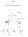
Fig. 2 } A figure is a first conceptual diagram of an embodiment of the present invention. - {
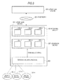
Fig. 3 } A figure is a second conceptual diagram of the embodiment of the present invention. - {
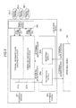
Fig. 4 } A figure is a block diagram illustrating an internal configuration of a lower main device according to the embodiment of the present invention. - {
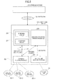
Fig. 5 } A figure is a block diagram for explaining a function when a failure occurs in an IP network in the embodiment of the present invention. - Hereinafter, an embodiment for implementing the present invention will be described in detail with reference to the drawings.
- As illustrated in
Fig. 2 , a configuration is employed with the present embodiment where a plurality of digital terminals 301-1, 301-2, ... and 301-n are housed in one digital terminal housing device (lower main device) 201 using aterminal housing package 203, and the plurality of digital terminals 301-1, 301-2, ... and 301-n are collectively connected to an uppermain device 101 through the lowermain device 201 and through an IP network. - That is, instead of connecting each IP terminal to the upper main device, one lower
main device 201 collectively houses and manages the plurality of digital terminals 301-1, 301-2, ... and 301-n. - The lower
main device 201 collectively performs communication between the upper main device and all digital terminals to be connected to the lowermain device 201. - By this means, only one lower
main device 201 needs to be connected with the uppermain device 101 through anIP network 151. - By so doing, IP terminals which require a great amount of cost can be replaced with low-cost digital terminals, so that the lower
main device 201 can collectively manage the plurality of digital terminals 301-1, 301-2, ... and 301-n and substantially reduce management labor required per terminal. - Further, the lower
main device 201 which is originally operating as the main device is used, so that, upon failure in theIP network 151, the lowermain device 201 can stop communication with the upper main device and operate as an independent main device. Consequently, the plurality of digital terminals 301-1, 301-2, ... and 301-n can be connected to apublic line 161 through theterminal housing package 203 and ananalog housing package 221 of the lowermain device 201. - In the present embodiment, by incorporating an existing mechanism of connecting IP terminals in the lower
main device 201, the target function is easily realized, and an interface between the uppermain device 101 and the lowermain device 201 is multiplexed with an interface between anupper device 901 and anIP terminal 903 illustrated inFig. 1 . As illustrated inFig. 3 , the lowermain device 201 is virtually implemented inside an IP terminal module 209 (including submodules 209-1, 209-2, ... and 209-n per IP terminal), and each of the submodules 209-1, 209-2, ... and 209-n of theIP terminal module 209 transmits/receives messages with the upper main device. - That is, when the digital terminal 301-i (i is a value of one of 1, 2, ... and n) connects to the
terminal housing package 203 of the lowermain device 201, theIP terminal 209 notifies a message to the uppermain device 101 as if the IP terminal were connected, and performs resist processing of SIP (Session Initiation Protocol). By so doing, the uppermain device 101 can recognize that the digital terminal 301-i is connected to the lowermain device 201 in the same way how the IP terminal is connected, and perform control in the same way how the IP terminal is controlled. - That is, when the digital terminal 301-i is off-hooked, if the
IP terminal module 209 notifies a message to the uppermain device 101 in the same way as the way when the IP terminal is off-hooked and the uppermain device 101 transmits a message (including a message for a display instruction (such as an LCD or LED instruction)) to the lowermain device 201 in the same way as the way for the IP terminal, a terminal instructiondata conversion module 207b of the lowermain device 201 converts the message into a message for the digital terminal 301-i and outputs the message to theterminal housing package 203. - By so doing, the upper
main device 101 can perform control in the same way as how the IP terminal is connected without particularly concerning that the subordinate digital terminal 301-i of the lowermain device 201 is connected. - Further, the lower
main device 201 can also easily control the digital terminal 301-i by utilizing a control module implemented in the IP terminal as theIP terminal module 209. - These processing are independently performed for digital terminals to be connected using the submodules 209-1, 209-2, ... and 209-i inside the
IP terminal module 209 and submodules 207-1, 207-2, ... and 207-n inside theconversion module 207. - As illustrated in
Fig. 5 , although it is possible to establish connection with the uppermain device 101 and perform the operation by performing the above control upon a normal operation, when a failure occurs in theIP network 151, it is possible to switch an operation mode and transition to the original operation of the main device using a main devicenormal operation module 223 and an analogline housing package 221. - According to a configuration example in
Fig. 3 , the uppermain device 101 and the lowermain device 201 are connected through theIP network 151. The lowermain device 201 houses the digital terminals 301-1, 301-2, ... and 301-n through theterminal housing package 203. - A conceptual diagram illustrated in
Fig. 3 will be additionally described focusing on a flow of a message. - Referring to
Fig. 4 , the digital terminal instruction data refers to data for giving an instruction of the lowermain device 201 to the digital terminals 301-1, 301-2, ... and 301-n to change the LCD, the LED and the like. The digital terminal information data refers to data for notifying from the digital terminals 301-1, 301-2, ... and 301-n to the lowermain device 201 that a button is pushed or terminal information indicating off-hook and the like. - The IP terminal instruction data and the IP terminal information data refer to terminal instruction data and terminal information data in the IP
terminal control module 209, respectively. - The
conversion module 207 converts the IP terminal instruction data into digital terminal instruction data for a digital terminal. Further, theconversion module 207 converts the digital terminal information data for the digital terminal into IP terminal information data. TheIP terminal module 209 plays a role of establishing connection with the uppermain device 101, and transmitting/receiving the IP terminal instruction data and the IP terminal information data to and from the uppermain device 101. - When the digital terminal 301-i is off-hooked, the digital terminal information data is transmitted from the
terminal housing package 203 to the terminal informationdata conversion module 207a, and the terminal informationdata conversion module 207a converts the digital terminal information data into IP terminal information data and passes the IP terminal information data to theIP terminal module 209. - The
transmission module 209a in theIP terminal module 209 multiplexes the IP terminal information data of each digital terminal inputted from the terminal informationdata conversion module 207a, and transmits the IP terminal information data to the uppermain device 101. - When receiving the IP terminal information data, the upper
main device 101 recognizes that the digital terminal 301-i is off-hooked, and transmits the IP terminal instruction data to theIP terminal module 209 to change content of the LCD or the LED. - The
reception module 209b of theIP terminal module 209 receives the IP terminal instruction data, demultiplexes the IP terminal instruction data to IP terminal instruction data of each digital terminal and outputs the IP terminal instruction data of each digital terminal to theconversion module 207. - The terminal instruction
data conversion module 207b in theconversion module 207 converts the IP terminal instruction data matching the digital terminal 301-i into digital terminal instruction data for the digital terminal 301-i, and outputs the digital terminal instruction data to theterminal housing package 203. - Under the above control, when the digital terminal 301-i is off-hooked, the LCD or the LED of the digital terminal 301-i can be changed according to the instruction of the upper
main device 101. - As to the other operations, a basic control flow is the same as the above, and the digital terminal 301-i can be operated under this control. By repeating the same control as the above a plurality of times, the digital terminal 301-i can be connected to the upper
main device 101. - If, during this repetition, the digital terminal transmits digital terminal information data indicating that a call operation to the digital terminal is performed, to the terminal information
data conversion module 207a through theterminal housing package 203, the terminal informationdata conversion module 207a converts this digital terminal information data into IP terminal information representing an INVITE message of SIP and outputs this IP terminal information data. When the terminal instructiondata conversion module 207b receives the IP terminal instruction data representing 180 ringing of SIP from the uppermain device 101 through thereception module 209b, the terminal instructiondata conversion module 207b converts this IP terminal information data into digital terminal instruction data for displaying ringing on the LCD or the LED, and outputs this digital terminal instruction data to the digital terminal through theterminal housing package 203. When the terminal instructiondata conversion module 207b receives the IP terminal instruction data representing 200 OK ringing of SIP of a communicating party from the uppermain device 101 through thereception module 209b, the terminal instructiondata conversion module 207b converts this IP terminal information data into digital terminal instruction data for notifying the off-hook of the communicating party to the LCD or the LED and outputs the digital terminal instruction data to the digital terminal through theterminal housing package 203. When the digital terminal transmits a response signal corresponding to digital terminal instruction data as digital terminal information data to the terminal informationdata conversion module 207a through theterminal housing package 203, the terminal informationdata conversion module 207a converts this digital terminal information data, into IP terminal information data representing an ACK message of SIP, and outputs this IP terminal information data. - The upper
main device 101 controls terminals based on IP terminal instruction data and IP terminal information data and, consequently, basically does not need to care that a terminal is a digital terminal connected through the lowermain device 201. - Next, an operation upon occurrence of failure will be described.
- Referring to
Fig. 5 , under a normal operation, data from theterminal housing package 203 is transmitted to theconversion module 207, and is transmitted to the upper main device through theIP terminal module 209 as described above. Although the lowermain device 201 monitors a state of connection with the uppermain device 101 through theIP network 151 at all times and processes data in this connected state if the connected state is normal, when an abnormal connected state continues for a certain period of time, data from theterminal housing package 203 is processed by a main device function of the main devicenormal operation module 223 of the lowermain device 201, and a mode is switched to an abnormality mode for allowing the lowermain device 201 to control the digital terminal 301-i. - The abnormality mode refers to a mode in which the lower
main device 201 originally functions as the main device, under the abnormality mode, the housed analogline housing package 221 can also connect the digital terminal 301-i to, for example, a phone connected to thepublic line 161. By this means, even when the lowermain device 201 and the uppermain device 101 are disconnected, the digital terminal 301-i can use thepublic line 161 and it is possible to avoid a situation in which the digital terminal 301-i cannot perform communication. - Although an example has been described with the above embodiment where digital terminals are used instead of IP terminals, the embodiment can be modified such that analog terminals are used instead of IP terminals. Further, the above embodiment can also be modified to support a line control.
- The lower main device according to the above embodiment can be realized by hardware, software or a combination thereof. The software can be realized by causing a computer to read and execute a program.
- According to the embodiment, by effectively utilizing the existing mechanism of controlling IP terminals and regarding the lower main device as a plurality of so-called IP terminals, the lower main device can be realized through efficient IP connection.
- Further, by comparing with the upper main device, using the lower main device with a system of small capacity, it is possible to significantly reduce entire cost compared to a system in which a plurality of terminals are connected to the upper main device.
- In addition, by making an access to the lower main device through the IP network using a configuration tool, it is possible to collectively set a resist destination of a digital terminal to be connected to the lower main device and significantly improve constructionability and maintainability.
- Further, even when the lower main device and the upper main device cannot be connected, the digital terminal connected to the lower main device can use the public line and it is possible to improve survivability.
- Although a part or entirety of the above embodiment can be disclosed as the following supplemental notes, the part or entirety of the above embodiment is not limited to the following supplemental notes.
- A lower main device behaves as one or more IP terminals with respect to an upper main device, and houses one or more non-IP terminals corresponding to the one or more IP terminals.
- The lower main device described in supplemental note 1, has:
- a terminal housing package that houses the one or more non-IP terminals;
- a terminal information data conversion module that receives an input of non-IP terminal information data outputted by each non-IP terminal through the terminal housing package, and that converts the non-IP terminal information data into IP terminal information data related to each non-IP terminal;
- a transmission module that multiplexes the IP terminal information data outputted by the terminal information data conversion module and related to each non-IP terminal, and that transmits the IP terminal information data to the upper main device through an IP network;
- a reception module that demultiplexes IP terminal instruction data received from the upper main device through the IP network, and that outputs the IP terminal instruction data related to each non-IP terminal; and
- a terminal instruction data conversion module that receives an input of the IP terminal instruction data outputted by the reception module and related to each non-IP terminal, converts the IP terminal instruction data into non-IP terminal instruction data related to each non-IP terminal and outputs the non-IP terminal instruction data related to each non-IP terminal to the terminal housing package, wherein the terminal housing package outputs to each non-IP terminal the non-IP terminal instruction data inputted from the terminal instruction data conversion module and related to each non-IP terminal.
- The lower main device described in supplemental note 1 or 2,
further has a main device functioning unit, and, when a state of communication with the upper main device becomes abnormal, the main device functioning unit functions in place of the upper main device. - A non-IP terminal housing method includes behaving as one or more IP terminals with respect to an upper main device, and housing one or more non-IP terminals corresponding to the one or more IP terminals.
- The non-IP terminal housing method described in supplemental note 4 includes:
- a step of, at a terminal information data conversion module, inputting non-IP terminal information data outputted by each non-IP terminal through the terminal housing package, and converting the non-IP terminal information data into IP terminal information data related to each non-IP terminal;
- a step of, at a transmission module, multiplexing the IP terminal information data outputted by the terminal information data conversion module and related to each non-IP terminal, and transmitting the IP terminal information data to the upper main device through an IP network;
- a step of, at a reception module, demultiplexing IP terminal instruction data received from the upper main device through the IP network, and outputting the IP terminal instruction data related to each non-IP terminal; and
- a step of, at a terminal instruction data conversion module, inputting the IP terminal instruction data outputted by the reception module and related to each non-IP terminal, converting the IP terminal instruction data into non-IP terminal instruction data related to each non-IP terminal and outputting the non-IP terminal instruction data related to each non-IP terminal through the terminal housing package
- The non-IP terminal housing method described in supplemental note 4 or 5, further includes a step of, when a state of communication with the upper main device becomes abnormal, at the main device functioning unit, functioning in place of the upper main device.
- A program causes a computer to execute a non-IP terminal housing method of behaving as one or more IP terminals with respect to an upper main device, and housing one or more non-IP terminals corresponding to the one or more IP terminals.
- In the program described in supplemental note 7,
the non-IP terminal housing method includes: - a step of, at a terminal information data conversion module, inputting non-IP terminal information data outputted by each non-IP terminal through the terminal housing package, and converting the non-IP terminal information data into IP terminal information data related to each non-IP terminal;
- a step of, at a transmission module, multiplexing the IP terminal information data outputted by the terminal information data conversion module and related to each non-IP terminal, and transmitting the IP terminal information data to the upper main device through an IP network;
- a step of, at a reception module, demultiplexing IP terminal instruction data received from the upper main device through the IP network, and outputting the IP terminal instruction data related to each non-IP terminal; and
- a step of, at a terminal instruction data conversion module, inputting the IP terminal instruction data outputted by the reception module and related to each non-IP terminal, converting the IP terminal instruction data into non-IP terminal instruction data related to each non-IP terminal and outputting the non-IP terminal instruction data related to each non-IP terminal through the terminal housing package
- In the program described in supplemental note 7 or 8,
the non-IP terminal housing method further includes a step of, when a state of communication with the upper main device becomes abnormal, at the main device functioning unit, functioning in place of the upper main device. - The program can be stored using various types of non-transitory computer readable media and supplied to the computer. The various types of non-transitory computer readable media include various types of tangible storage media. The various types of non-transitory computer readable media include, for example, a magnetic recording medium (for example, a flexible disk, a magnetic tape and a hard disk drive), a magnetooptical recording medium (for example, a magnetooptical disk), a CD-ROM (Read Only Memory), a CD-R, a CD-R/W, and a semiconductor memory (for example, a mask ROM, a PROM (Programmable ROM), an EPROM (Erasable PROM), a flash ROM and a RAM (random access memory)). Further, the program may be supplied to the computer using various types of transitory computer readable media. The transitory computer readable media include, for example, an electric signal, an optical signal and an electromagnetic wave. The transitory computer readable media can allow a program to be supplied to the computer through a wired communication channel such as electric wires or optical wires or wireless communication channels.
- This application is based on Japanese Patent Application No.
2010-235518 (filed on October 20, 2010 2010-235518 2010-235518 2010-235518 - Although the typical embodiment of the present invention has been described in detail, it should be understood that various changes, substitutions and alternatives can be made without deviating from the spirit and the scope of the invention defined by the claims. Further, even if the claims are amended upon application procedure, the inventors intend that a uniform scope of the claimed invention is maintained.
- The present invention can be utilized to connect a plurality of non-IP terminals to a main device.
-
- 101 UPPER MAIN DEVICE
- 151 IP NETWORK
- 201 DIGITAL TERMINAL HOUSING DEVICE (LOWER MAIN DEVICE)
- 203 TERMINAL HOUSING PACKAGE
- 207 CONVERSION MODULE
- 207a TERMINAL INFORMATION DATA CONVERSION MODULE
- 207b TERMINAL INSTRUCTION DATA CONVERSION MODULE
- 209 IP TERMINAL MODULE
- 209a TRANSMISSION MODULE
- 209b RECEPTION MODULE
- 221 ANALOG LINE HOUSING PACKAGE
- 223 MAIN DEVICE NORMAL OPERATION MODULE
- 301-1 TO 301-n DIGITAL TERMINAL
Claims (9)
- A lower main device that behaves as one or more IP terminals with respect to an upper main device, and that houses one or more non-IP terminals corresponding to the one or more IP terminals.
- The lower main device according to claim 1, comprising:a terminal housing package that houses the one or more non-IP terminals;a terminal information data conversion module that receives an input of non-IP terminal information data outputted by each non-IP terminal through the terminal housing package, and that converts the non-IP terminal information data into IP terminal information data related to each non-IP terminal;a transmission module that multiplexes the IP terminal information data outputted by the terminal information data conversion module and related to each non-IP terminal, and that transmits the IP terminal information data to the upper main device through an IP network;a reception module that demultiplexes IP terminal instruction data received from the upper main device through the IP network, and that outputs the IP terminal instruction data related to each non-IP terminal; anda terminal instruction data conversion module that receives an input of the IP terminal instruction data outputted by the reception module and related to each non-IP terminal, converts the IP terminal instruction data into non-IP terminal instruction data related to each non-IP terminal and outputs the non-IP terminal instruction data related to each non-IP terminal to the terminal housing package,wherein the terminal housing package outputs to each non-IP terminal the non-IP terminal instruction data inputted from the terminal instruction data conversion module and related to each non-IP terminal.
- The lower main device according to claim 1 or 2, further comprising a main device functioning unit, wherein, when a state of communication with the upper main device becomes abnormal, the main device functioning unit functions in place of the upper main device.
- A non-IP terminal housing method of behaving as one or more IP terminals with respect to an upper main device, and housing one or more non-IP terminals corresponding to the one or more IP terminals.
- The non-IP terminal housing method according to claim 4, comprising:a step of, at a terminal information data conversion module, inputting non-IP terminal information data outputted by each non-IP terminal through the terminal housing package, and converting the non-IP terminal information data into IP terminal information data related to each non-IP terminal;a step of, at a transmission module, multiplexing the IP terminal information data outputted by the terminal information data conversion module and related to each non-IP terminal, and transmitting the IP terminal information data to the upper main device through an IP network;a step of, at a reception module, demultiplexing IP terminal instruction data received from the upper main device through the IP network, and outputting the IP terminal instruction data related to each non-IP terminal; anda step of, at a terminal instruction data conversion module, inputting the IP terminal instruction data outputted by the reception module and related to each non-IP terminal, converting the IP terminal instruction data into non-IP terminal instruction data related to each non-IP terminal and outputting to each non-IP terminal the non-IP terminal instruction data related to each non-IP terminal through the terminal housing package.
- The non-IP terminal housing method according to claim 4 or 5, further comprising a step of, when a state of communication with the upper main device becomes abnormal, at the main device functioning unit, functioning in place of the upper main device.
- A program causing a computer to execute a non-IP terminal housing method of behaving as one or more IP terminals with respect to an upper main device, and housing one or more non-IP terminals corresponding to the one or more IP terminals.
- The program according to claim 7, wherein
the non-IP terminal housing method comprises:a step of, at a terminal information data conversion module, inputting non-IP terminal information data outputted by each non-IP terminal through the terminal housing package, and converting the non-IP terminal information data into IP terminal information data related to each non-IP terminal;a step of, at a transmission module, multiplexing the IP terminal information data outputted by the terminal information data conversion module and related to each non-IP terminal, and transmitting the IP terminal information data to the upper main device through an IP network;a step of, at a reception module, demultiplexing IP terminal instruction data received from the upper main device through the IP network, and outputting the IP terminal instruction data related to each non-IP terminal; anda step of, at a terminal instruction data conversion module, inputting the IP terminal instruction data outputted by the reception module and related to each non-IP terminal, converting the IP terminal instruction data into non-IP terminal instruction data related to each non-IP terminal and outputting to each non-IP terminal the non-IP terminal instruction data related to each non-IP terminal through the terminal housing package. - The program according to claim 7 or 8,
wherein the non-IP terminal housing method further comprises a step of, when a state of communication with the upper main device becomes abnormal, at the main device functioning unit, functioning in place of the upper main device.
Applications Claiming Priority (2)
| Application Number | Priority Date | Filing Date | Title |
|---|---|---|---|
| JP2010235518A JP5093534B2 (en) | 2010-10-20 | 2010-10-20 | Subordinate main apparatus and non-IP terminal accommodating method |
| PCT/JP2011/055796 WO2012053234A1 (en) | 2010-10-20 | 2011-03-11 | Lower main device and non-ip terminal housing method |
Publications (3)
| Publication Number | Publication Date |
|---|---|
| EP2597888A1 true EP2597888A1 (en) | 2013-05-29 |
| EP2597888A4 EP2597888A4 (en) | 2013-11-06 |
| EP2597888B1 EP2597888B1 (en) | 2014-10-29 |
Family
ID=45974962
Family Applications (1)
| Application Number | Title | Priority Date | Filing Date |
|---|---|---|---|
| EP11834079.3A Not-in-force EP2597888B1 (en) | 2010-10-20 | 2011-03-11 | Lower main device and non-ip terminal housing method |
Country Status (7)
| Country | Link |
|---|---|
| US (1) | US8611341B2 (en) |
| EP (1) | EP2597888B1 (en) |
| JP (1) | JP5093534B2 (en) |
| CN (1) | CN103109543B (en) |
| AU (1) | AU2011319298B2 (en) |
| CA (1) | CA2811412C (en) |
| WO (1) | WO2012053234A1 (en) |
Family Cites Families (16)
| Publication number | Priority date | Publication date | Assignee | Title |
|---|---|---|---|---|
| JP3708656B2 (en) * | 1997-02-04 | 2005-10-19 | 株式会社東芝 | Communications system |
| JP3967492B2 (en) * | 1999-06-17 | 2007-08-29 | 沖電気工業株式会社 | Voice terminal storage device |
| KR100876760B1 (en) | 2001-10-13 | 2009-01-07 | 삼성전자주식회사 | Call Processing Message Converter and Message Converting Method in Internet Protocol Telephony System |
| AU2002301409B2 (en) * | 2001-10-13 | 2003-11-06 | Samsung Electronics Co., Ltd. | Internet protocol telephony exchange system and call control method thereof |
| JP4257274B2 (en) | 2004-08-11 | 2009-04-22 | Necアクセステクニカ株式会社 | Bitmap optimization method between ADSL modem and ADSL modem |
| JP4444144B2 (en) | 2005-03-16 | 2010-03-31 | 株式会社東芝 | Gateway device |
| JP4765438B2 (en) * | 2005-06-30 | 2011-09-07 | 沖電気工業株式会社 | IP-PBX system |
| JP2007336022A (en) | 2006-06-13 | 2007-12-27 | Matsushita Electric Ind Co Ltd | Digital broadcast redistribution system and distribution apparatus |
| JP5196547B2 (en) * | 2007-05-21 | 2013-05-15 | Necインフロンティア株式会社 | Main device, method of mounting multi-functional unit on main device, and program thereof |
| JP4569655B2 (en) * | 2008-03-26 | 2010-10-27 | ブラザー工業株式会社 | Information communication terminal |
| JP5146877B2 (en) * | 2008-03-31 | 2013-02-20 | Necインフロンティア株式会社 | Method and system for incoming call history registration and outgoing call using the registered information |
| JP5112165B2 (en) * | 2008-05-09 | 2013-01-09 | 株式会社日立製作所 | Communication device |
| JP2010124456A (en) | 2008-10-21 | 2010-06-03 | Toshiba Corp | Communication system, communication apparatus and terminal accommodation apparatus |
| JP2010103652A (en) | 2008-10-22 | 2010-05-06 | Nec Corp | Network system and analog video synchronizing signal transmission method for use in same |
| CN101729699B (en) * | 2008-10-25 | 2012-02-01 | 华为技术有限公司 | Separation equipment and method for transmitting voice signal |
| JP5488786B2 (en) | 2009-03-31 | 2014-05-14 | 宇部興産株式会社 | Process for producing azaboracyclopentene compound and synthetic intermediate thereof |
-
2010
- 2010-10-20 JP JP2010235518A patent/JP5093534B2/en active Active
-
2011
- 2011-03-11 CN CN201180043587.9A patent/CN103109543B/en not_active Expired - Fee Related
- 2011-03-11 CA CA2811412A patent/CA2811412C/en active Active
- 2011-03-11 AU AU2011319298A patent/AU2011319298B2/en not_active Ceased
- 2011-03-11 WO PCT/JP2011/055796 patent/WO2012053234A1/en not_active Ceased
- 2011-03-11 EP EP11834079.3A patent/EP2597888B1/en not_active Not-in-force
- 2011-03-11 US US13/818,870 patent/US8611341B2/en active Active
Also Published As
| Publication number | Publication date |
|---|---|
| US20130156046A1 (en) | 2013-06-20 |
| CA2811412C (en) | 2013-10-08 |
| EP2597888B1 (en) | 2014-10-29 |
| US8611341B2 (en) | 2013-12-17 |
| CA2811412A1 (en) | 2012-04-26 |
| EP2597888A4 (en) | 2013-11-06 |
| JP2012124544A (en) | 2012-06-28 |
| CN103109543A (en) | 2013-05-15 |
| JP5093534B2 (en) | 2012-12-12 |
| CN103109543B (en) | 2015-01-28 |
| AU2011319298B2 (en) | 2014-01-30 |
| HK1181231A1 (en) | 2013-11-01 |
| AU2011319298A1 (en) | 2013-03-07 |
| WO2012053234A1 (en) | 2012-04-26 |
Similar Documents
| Publication | Publication Date | Title |
|---|---|---|
| KR100521154B1 (en) | Apparatus and method processing call in voice/data integration switching system | |
| KR100705568B1 (en) | Apparatus and Method for Processing S Eye Signaling in Integrated Voice / Data Exchange System | |
| NO322051B1 (en) | Transmission of data on multi-speed networks | |
| US7489677B2 (en) | Exchange equipment | |
| AU2011319298B2 (en) | Lower main device and non-IP terminal housing method | |
| CN1112008C (en) | Internet telephone switching system | |
| US7508821B2 (en) | Method for setting up a data connection between terminal devices | |
| EP2088759A1 (en) | A method, telephone system and telephone terminal for calling session | |
| US20070064677A1 (en) | Packet media gateway with a secondary PSTN connection and method for time slot switching | |
| HK1181231B (en) | Lower main device and non-ip terminal housing method | |
| CN105472188A (en) | Method and system for realizing telephone scheduling | |
| US6621814B1 (en) | Method and apparatus for transmitting voice data in data packets with additional supplementary services | |
| US20050169241A1 (en) | Integrated voice and data switching system | |
| JP2012015981A (en) | Communication system | |
| EP1650939A1 (en) | Gateway device, private branch exchange system, and private branch exchange method | |
| JP2001237897A (en) | Hybrid type telephony system | |
| JP4765438B2 (en) | IP-PBX system | |
| JP3334610B2 (en) | Audio level setting method | |
| JP4420330B2 (en) | Telephone system | |
| JPH07123172A (en) | Terminal device | |
| JP2004201054A (en) | Apparatus and method for communication control | |
| KR100428772B1 (en) | Key-phone system with voice-over digital subscriber line | |
| EP2504983B1 (en) | Method and gateway device for transmitting a caller number | |
| JP6567221B2 (en) | Communications system | |
| JP2009141712A (en) | Relay device and relay method |
Legal Events
| Date | Code | Title | Description |
|---|---|---|---|
| PUAI | Public reference made under article 153(3) epc to a published international application that has entered the european phase |
Free format text: ORIGINAL CODE: 0009012 |
|
| 17P | Request for examination filed |
Effective date: 20130225 |
|
| AK | Designated contracting states |
Kind code of ref document: A1 Designated state(s): AL AT BE BG CH CY CZ DE DK EE ES FI FR GB GR HR HU IE IS IT LI LT LU LV MC MK MT NL NO PL PT RO RS SE SI SK SM TR |
|
| A4 | Supplementary search report drawn up and despatched |
Effective date: 20131009 |
|
| RIC1 | Information provided on ipc code assigned before grant |
Ipc: H04M 3/00 20060101ALI20131003BHEP Ipc: H04L 12/28 20060101ALI20131003BHEP Ipc: H04Q 3/58 20060101AFI20131003BHEP |
|
| DAX | Request for extension of the european patent (deleted) | ||
| RIC1 | Information provided on ipc code assigned before grant |
Ipc: H04L 12/28 20060101ALI20140211BHEP Ipc: H04Q 3/58 20060101AFI20140211BHEP Ipc: H04M 3/00 20060101ALI20140211BHEP Ipc: H04M 1/253 20060101ALI20140211BHEP |
|
| GRAP | Despatch of communication of intention to grant a patent |
Free format text: ORIGINAL CODE: EPIDOSNIGR1 |
|
| INTG | Intention to grant announced |
Effective date: 20140424 |
|
| GRAS | Grant fee paid |
Free format text: ORIGINAL CODE: EPIDOSNIGR3 |
|
| GRAA | (expected) grant |
Free format text: ORIGINAL CODE: 0009210 |
|
| AK | Designated contracting states |
Kind code of ref document: B1 Designated state(s): AL AT BE BG CH CY CZ DE DK EE ES FI FR GB GR HR HU IE IS IT LI LT LU LV MC MK MT NL NO PL PT RO RS SE SI SK SM TR |
|
| RAP1 | Party data changed (applicant data changed or rights of an application transferred) |
Owner name: NEC INFRONTIA CORPORATION |
|
| REG | Reference to a national code |
Ref country code: GB Ref legal event code: FG4D |
|
| REG | Reference to a national code |
Ref country code: CH Ref legal event code: EP |
|
| REG | Reference to a national code |
Ref country code: AT Ref legal event code: REF Ref document number: 694039 Country of ref document: AT Kind code of ref document: T Effective date: 20141115 |
|
| REG | Reference to a national code |
Ref country code: IE Ref legal event code: FG4D |
|
| REG | Reference to a national code |
Ref country code: DE Ref legal event code: R096 Ref document number: 602011011023 Country of ref document: DE Effective date: 20141211 |
|
| REG | Reference to a national code |
Ref country code: AT Ref legal event code: MK05 Ref document number: 694039 Country of ref document: AT Kind code of ref document: T Effective date: 20141029 |
|
| REG | Reference to a national code |
Ref country code: NL Ref legal event code: VDEP Effective date: 20141029 |
|
| REG | Reference to a national code |
Ref country code: LT Ref legal event code: MG4D |
|
| RAP2 | Party data changed (patent owner data changed or rights of a patent transferred) |
Owner name: NEC PLATFORMS, LTD. |
|
| PG25 | Lapsed in a contracting state [announced via postgrant information from national office to epo] |
Ref country code: NO Free format text: LAPSE BECAUSE OF FAILURE TO SUBMIT A TRANSLATION OF THE DESCRIPTION OR TO PAY THE FEE WITHIN THE PRESCRIBED TIME-LIMIT Effective date: 20150129 Ref country code: NL Free format text: LAPSE BECAUSE OF FAILURE TO SUBMIT A TRANSLATION OF THE DESCRIPTION OR TO PAY THE FEE WITHIN THE PRESCRIBED TIME-LIMIT Effective date: 20141029 Ref country code: PT Free format text: LAPSE BECAUSE OF FAILURE TO SUBMIT A TRANSLATION OF THE DESCRIPTION OR TO PAY THE FEE WITHIN THE PRESCRIBED TIME-LIMIT Effective date: 20150302 Ref country code: ES Free format text: LAPSE BECAUSE OF FAILURE TO SUBMIT A TRANSLATION OF THE DESCRIPTION OR TO PAY THE FEE WITHIN THE PRESCRIBED TIME-LIMIT Effective date: 20141029 Ref country code: FI Free format text: LAPSE BECAUSE OF FAILURE TO SUBMIT A TRANSLATION OF THE DESCRIPTION OR TO PAY THE FEE WITHIN THE PRESCRIBED TIME-LIMIT Effective date: 20141029 Ref country code: IS Free format text: LAPSE BECAUSE OF FAILURE TO SUBMIT A TRANSLATION OF THE DESCRIPTION OR TO PAY THE FEE WITHIN THE PRESCRIBED TIME-LIMIT Effective date: 20150228 Ref country code: LT Free format text: LAPSE BECAUSE OF FAILURE TO SUBMIT A TRANSLATION OF THE DESCRIPTION OR TO PAY THE FEE WITHIN THE PRESCRIBED TIME-LIMIT Effective date: 20141029 |
|
| PG25 | Lapsed in a contracting state [announced via postgrant information from national office to epo] |
Ref country code: CY Free format text: LAPSE BECAUSE OF FAILURE TO SUBMIT A TRANSLATION OF THE DESCRIPTION OR TO PAY THE FEE WITHIN THE PRESCRIBED TIME-LIMIT Effective date: 20141029 Ref country code: RS Free format text: LAPSE BECAUSE OF FAILURE TO SUBMIT A TRANSLATION OF THE DESCRIPTION OR TO PAY THE FEE WITHIN THE PRESCRIBED TIME-LIMIT Effective date: 20141029 Ref country code: HR Free format text: LAPSE BECAUSE OF FAILURE TO SUBMIT A TRANSLATION OF THE DESCRIPTION OR TO PAY THE FEE WITHIN THE PRESCRIBED TIME-LIMIT Effective date: 20141029 Ref country code: GR Free format text: LAPSE BECAUSE OF FAILURE TO SUBMIT A TRANSLATION OF THE DESCRIPTION OR TO PAY THE FEE WITHIN THE PRESCRIBED TIME-LIMIT Effective date: 20150130 Ref country code: AT Free format text: LAPSE BECAUSE OF FAILURE TO SUBMIT A TRANSLATION OF THE DESCRIPTION OR TO PAY THE FEE WITHIN THE PRESCRIBED TIME-LIMIT Effective date: 20141029 Ref country code: SE Free format text: LAPSE BECAUSE OF FAILURE TO SUBMIT A TRANSLATION OF THE DESCRIPTION OR TO PAY THE FEE WITHIN THE PRESCRIBED TIME-LIMIT Effective date: 20141029 Ref country code: PL Free format text: LAPSE BECAUSE OF FAILURE TO SUBMIT A TRANSLATION OF THE DESCRIPTION OR TO PAY THE FEE WITHIN THE PRESCRIBED TIME-LIMIT Effective date: 20141029 Ref country code: LV Free format text: LAPSE BECAUSE OF FAILURE TO SUBMIT A TRANSLATION OF THE DESCRIPTION OR TO PAY THE FEE WITHIN THE PRESCRIBED TIME-LIMIT Effective date: 20141029 |
|
| REG | Reference to a national code |
Ref country code: DE Ref legal event code: R097 Ref document number: 602011011023 Country of ref document: DE |
|
| PG25 | Lapsed in a contracting state [announced via postgrant information from national office to epo] |
Ref country code: DK Free format text: LAPSE BECAUSE OF FAILURE TO SUBMIT A TRANSLATION OF THE DESCRIPTION OR TO PAY THE FEE WITHIN THE PRESCRIBED TIME-LIMIT Effective date: 20141029 Ref country code: EE Free format text: LAPSE BECAUSE OF FAILURE TO SUBMIT A TRANSLATION OF THE DESCRIPTION OR TO PAY THE FEE WITHIN THE PRESCRIBED TIME-LIMIT Effective date: 20141029 Ref country code: SK Free format text: LAPSE BECAUSE OF FAILURE TO SUBMIT A TRANSLATION OF THE DESCRIPTION OR TO PAY THE FEE WITHIN THE PRESCRIBED TIME-LIMIT Effective date: 20141029 Ref country code: RO Free format text: LAPSE BECAUSE OF FAILURE TO SUBMIT A TRANSLATION OF THE DESCRIPTION OR TO PAY THE FEE WITHIN THE PRESCRIBED TIME-LIMIT Effective date: 20141029 Ref country code: CZ Free format text: LAPSE BECAUSE OF FAILURE TO SUBMIT A TRANSLATION OF THE DESCRIPTION OR TO PAY THE FEE WITHIN THE PRESCRIBED TIME-LIMIT Effective date: 20141029 |
|
| PG25 | Lapsed in a contracting state [announced via postgrant information from national office to epo] |
Ref country code: IT Free format text: LAPSE BECAUSE OF FAILURE TO SUBMIT A TRANSLATION OF THE DESCRIPTION OR TO PAY THE FEE WITHIN THE PRESCRIBED TIME-LIMIT Effective date: 20141029 |
|
| PLBE | No opposition filed within time limit |
Free format text: ORIGINAL CODE: 0009261 |
|
| STAA | Information on the status of an ep patent application or granted ep patent |
Free format text: STATUS: NO OPPOSITION FILED WITHIN TIME LIMIT |
|
| 26N | No opposition filed |
Effective date: 20150730 |
|
| PG25 | Lapsed in a contracting state [announced via postgrant information from national office to epo] |
Ref country code: MC Free format text: LAPSE BECAUSE OF FAILURE TO SUBMIT A TRANSLATION OF THE DESCRIPTION OR TO PAY THE FEE WITHIN THE PRESCRIBED TIME-LIMIT Effective date: 20141029 Ref country code: LU Free format text: LAPSE BECAUSE OF FAILURE TO SUBMIT A TRANSLATION OF THE DESCRIPTION OR TO PAY THE FEE WITHIN THE PRESCRIBED TIME-LIMIT Effective date: 20150311 |
|
| REG | Reference to a national code |
Ref country code: CH Ref legal event code: PL |
|
| REG | Reference to a national code |
Ref country code: IE Ref legal event code: MM4A |
|
| PG25 | Lapsed in a contracting state [announced via postgrant information from national office to epo] |
Ref country code: CH Free format text: LAPSE BECAUSE OF NON-PAYMENT OF DUE FEES Effective date: 20150331 Ref country code: LI Free format text: LAPSE BECAUSE OF NON-PAYMENT OF DUE FEES Effective date: 20150331 Ref country code: IE Free format text: LAPSE BECAUSE OF NON-PAYMENT OF DUE FEES Effective date: 20150311 |
|
| REG | Reference to a national code |
Ref country code: FR Ref legal event code: PLFP Year of fee payment: 6 |
|
| PG25 | Lapsed in a contracting state [announced via postgrant information from national office to epo] |
Ref country code: SI Free format text: LAPSE BECAUSE OF FAILURE TO SUBMIT A TRANSLATION OF THE DESCRIPTION OR TO PAY THE FEE WITHIN THE PRESCRIBED TIME-LIMIT Effective date: 20141029 |
|
| PG25 | Lapsed in a contracting state [announced via postgrant information from national office to epo] |
Ref country code: MT Free format text: LAPSE BECAUSE OF FAILURE TO SUBMIT A TRANSLATION OF THE DESCRIPTION OR TO PAY THE FEE WITHIN THE PRESCRIBED TIME-LIMIT Effective date: 20141029 |
|
| REG | Reference to a national code |
Ref country code: FR Ref legal event code: PLFP Year of fee payment: 7 |
|
| PG25 | Lapsed in a contracting state [announced via postgrant information from national office to epo] |
Ref country code: SM Free format text: LAPSE BECAUSE OF FAILURE TO SUBMIT A TRANSLATION OF THE DESCRIPTION OR TO PAY THE FEE WITHIN THE PRESCRIBED TIME-LIMIT Effective date: 20141029 Ref country code: HU Free format text: LAPSE BECAUSE OF FAILURE TO SUBMIT A TRANSLATION OF THE DESCRIPTION OR TO PAY THE FEE WITHIN THE PRESCRIBED TIME-LIMIT; INVALID AB INITIO Effective date: 20110311 Ref country code: BG Free format text: LAPSE BECAUSE OF FAILURE TO SUBMIT A TRANSLATION OF THE DESCRIPTION OR TO PAY THE FEE WITHIN THE PRESCRIBED TIME-LIMIT Effective date: 20141029 |
|
| PG25 | Lapsed in a contracting state [announced via postgrant information from national office to epo] |
Ref country code: TR Free format text: LAPSE BECAUSE OF FAILURE TO SUBMIT A TRANSLATION OF THE DESCRIPTION OR TO PAY THE FEE WITHIN THE PRESCRIBED TIME-LIMIT Effective date: 20141029 |
|
| PG25 | Lapsed in a contracting state [announced via postgrant information from national office to epo] |
Ref country code: BE Free format text: LAPSE BECAUSE OF FAILURE TO SUBMIT A TRANSLATION OF THE DESCRIPTION OR TO PAY THE FEE WITHIN THE PRESCRIBED TIME-LIMIT Effective date: 20141029 |
|
| REG | Reference to a national code |
Ref country code: FR Ref legal event code: PLFP Year of fee payment: 8 |
|
| PG25 | Lapsed in a contracting state [announced via postgrant information from national office to epo] |
Ref country code: MK Free format text: LAPSE BECAUSE OF FAILURE TO SUBMIT A TRANSLATION OF THE DESCRIPTION OR TO PAY THE FEE WITHIN THE PRESCRIBED TIME-LIMIT Effective date: 20141029 |
|
| PG25 | Lapsed in a contracting state [announced via postgrant information from national office to epo] |
Ref country code: AL Free format text: LAPSE BECAUSE OF FAILURE TO SUBMIT A TRANSLATION OF THE DESCRIPTION OR TO PAY THE FEE WITHIN THE PRESCRIBED TIME-LIMIT Effective date: 20141029 |
|
| PGFP | Annual fee paid to national office [announced via postgrant information from national office to epo] |
Ref country code: DE Payment date: 20240320 Year of fee payment: 14 Ref country code: GB Payment date: 20240320 Year of fee payment: 14 |
|
| PGFP | Annual fee paid to national office [announced via postgrant information from national office to epo] |
Ref country code: FR Payment date: 20240327 Year of fee payment: 14 |
|
| REG | Reference to a national code |
Ref country code: DE Ref legal event code: R119 Ref document number: 602011011023 Country of ref document: DE |
|
| GBPC | Gb: european patent ceased through non-payment of renewal fee |
Effective date: 20250311 |
|
| PG25 | Lapsed in a contracting state [announced via postgrant information from national office to epo] |
Ref country code: DE Free format text: LAPSE BECAUSE OF NON-PAYMENT OF DUE FEES Effective date: 20251001 |
|
| PG25 | Lapsed in a contracting state [announced via postgrant information from national office to epo] |
Ref country code: GB Free format text: LAPSE BECAUSE OF NON-PAYMENT OF DUE FEES Effective date: 20250311 |
|
| PG25 | Lapsed in a contracting state [announced via postgrant information from national office to epo] |
Ref country code: FR Free format text: LAPSE BECAUSE OF NON-PAYMENT OF DUE FEES Effective date: 20250331 |