EP2597762A2 - Rotors of induction motors - Google Patents
Rotors of induction motors Download PDFInfo
- Publication number
- EP2597762A2 EP2597762A2 EP12185570.4A EP12185570A EP2597762A2 EP 2597762 A2 EP2597762 A2 EP 2597762A2 EP 12185570 A EP12185570 A EP 12185570A EP 2597762 A2 EP2597762 A2 EP 2597762A2
- Authority
- EP
- European Patent Office
- Prior art keywords
- rotor
- current
- rotor body
- radial slots
- radial
- Prior art date
- Legal status (The legal status is an assumption and is not a legal conclusion. Google has not performed a legal analysis and makes no representation as to the accuracy of the status listed.)
- Withdrawn
Links
- 230000006698 induction Effects 0.000 title claims abstract description 15
- 229910052782 aluminium Inorganic materials 0.000 claims description 17
- XAGFODPZIPBFFR-UHFFFAOYSA-N aluminium Chemical compound [Al] XAGFODPZIPBFFR-UHFFFAOYSA-N 0.000 claims description 16
- 230000015572 biosynthetic process Effects 0.000 claims description 14
- 229910000906 Bronze Inorganic materials 0.000 claims description 12
- 238000003475 lamination Methods 0.000 claims description 11
- 229910052802 copper Inorganic materials 0.000 claims description 7
- 239000010949 copper Substances 0.000 claims description 7
- RYGMFSIKBFXOCR-UHFFFAOYSA-N Copper Chemical compound [Cu] RYGMFSIKBFXOCR-UHFFFAOYSA-N 0.000 claims description 6
- 239000000463 material Substances 0.000 claims description 6
- XEEYBQQBJWHFJM-UHFFFAOYSA-N Iron Chemical compound [Fe] XEEYBQQBJWHFJM-UHFFFAOYSA-N 0.000 claims description 5
- PXHVJJICTQNCMI-UHFFFAOYSA-N Nickel Chemical compound [Ni] PXHVJJICTQNCMI-UHFFFAOYSA-N 0.000 claims description 5
- 230000000295 complement effect Effects 0.000 claims description 5
- 229910000976 Electrical steel Inorganic materials 0.000 claims description 3
- 239000011261 inert gas Substances 0.000 claims description 3
- 229910052742 iron Inorganic materials 0.000 claims description 3
- 229910052759 nickel Inorganic materials 0.000 claims description 3
- 229910017052 cobalt Inorganic materials 0.000 claims description 2
- 239000010941 cobalt Substances 0.000 claims description 2
- GUTLYIVDDKVIGB-UHFFFAOYSA-N cobalt atom Chemical compound [Co] GUTLYIVDDKVIGB-UHFFFAOYSA-N 0.000 claims description 2
- 230000005294 ferromagnetic effect Effects 0.000 claims description 2
- 239000000843 powder Substances 0.000 claims description 2
- WFKWXMTUELFFGS-UHFFFAOYSA-N tungsten Chemical compound [W] WFKWXMTUELFFGS-UHFFFAOYSA-N 0.000 claims description 2
- 229910052721 tungsten Inorganic materials 0.000 claims description 2
- 239000010937 tungsten Substances 0.000 claims description 2
- 238000005755 formation reaction Methods 0.000 description 7
- 230000000694 effects Effects 0.000 description 5
- 239000004020 conductor Substances 0.000 description 4
- 238000003466 welding Methods 0.000 description 4
- 229910045601 alloy Inorganic materials 0.000 description 3
- 239000000956 alloy Substances 0.000 description 3
- 230000007423 decrease Effects 0.000 description 3
- 238000000034 method Methods 0.000 description 3
- 239000000203 mixture Substances 0.000 description 3
- 239000010974 bronze Substances 0.000 description 2
- KUNSUQLRTQLHQQ-UHFFFAOYSA-N copper tin Chemical compound [Cu].[Sn] KUNSUQLRTQLHQQ-UHFFFAOYSA-N 0.000 description 2
- 230000002500 effect on skin Effects 0.000 description 2
- UFHFLCQGNIYNRP-UHFFFAOYSA-N Hydrogen Chemical compound [H][H] UFHFLCQGNIYNRP-UHFFFAOYSA-N 0.000 description 1
- 230000004075 alteration Effects 0.000 description 1
- 238000004581 coalescence Methods 0.000 description 1
- 230000003750 conditioning effect Effects 0.000 description 1
- 230000004907 flux Effects 0.000 description 1
- 239000001257 hydrogen Substances 0.000 description 1
- 229910052739 hydrogen Inorganic materials 0.000 description 1
- 238000005304 joining Methods 0.000 description 1
- 239000007788 liquid Substances 0.000 description 1
- 230000005291 magnetic effect Effects 0.000 description 1
- 229910052748 manganese Inorganic materials 0.000 description 1
- 230000003647 oxidation Effects 0.000 description 1
- 238000007254 oxidation reaction Methods 0.000 description 1
- 230000001737 promoting effect Effects 0.000 description 1
- 238000006467 substitution reaction Methods 0.000 description 1
Images



Classifications
-
- H—ELECTRICITY
- H02—GENERATION; CONVERSION OR DISTRIBUTION OF ELECTRIC POWER
- H02K—DYNAMO-ELECTRIC MACHINES
- H02K17/00—Asynchronous induction motors; Asynchronous induction generators
- H02K17/02—Asynchronous induction motors
- H02K17/16—Asynchronous induction motors having rotors with internally short-circuited windings, e.g. cage rotors
- H02K17/20—Asynchronous induction motors having rotors with internally short-circuited windings, e.g. cage rotors having deep-bar rotors
Definitions
- the present invention is directed to induction motors, and more particularly, rotors of induction motors.
- an induction motor includes a plurality of design specifications which are affected by an operating environment.
- One example of such a design specification is the starting current required to initiate rotation of an induction motor from rest.
- the starting current required to start the motor from rest may be increased above a feasible amount of current (e.g., as available from a power source such as a battery).
- cryogenic temperature ranges e.g., temperature ranges of a relatively low mean value, such as below -150 °C, -238 °F or 123 K
- the starting current may be even further affected, thereby negating the possibility of use of conventional rotor designs in cryogenic environments with available current limitations.
- a rotor of an induction motor includes a rotor body, the rotor body defining a central cavity configured to receive a motor shaft and having a plurality of radial slots formed therethrough, each radial slot of the plurality of radial slots extends outward radially from the central cavity to an outer surface of the rotor body, a plurality of current-conducting bars arranged within the plurality of radial slots of the rotor body, wherein each current-conducting bar of the plurality of current-conducting bars extend outward radially within each radial slot from the central cavity to the outer surface of the rotor body, a first end ring arranged on the rotor body in electrical communication with each current-conducting bar of the plurality of current-conducting bars, and a second end ring arranged on the rotor body in electrical communication with each current-conducting bar of the plurality of current-conducting bars.
- FIG. 1 is an isometric view of a rotor of an induction motor, according to an exemplary embodiment of the present invention
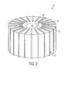
- FIG. 2 is an isometric view of rotor laminations of the rotor of FIG. 1 ;
- FIG. 3 is an isometric view of the rotor laminations and end rings of the rotor of FIG. 1 ;
- FIG. 4 is an expanded cross sectional view of an arc segment of the rotor laminations of the rotor of FIG. 1 ;
- FIG. 5 is a cross-sectional view of an induction motor, according to an exemplary embodiment of the present invention.
- an induction motor includes a plurality of design specifications, including a target starting current, which may be affected by an operating environment.
- a target starting current which may be affected by an operating environment.
- the starting current required to start the motor may exceed the specification and, thus, exclude conventional rotor designs in cryogenic environments.
- exemplary embodiments of the present invention provide a rotor of an induction motor which overcomes the drawbacks of conventional rotor designs in response to operation within cryogenic temperature ranges.
- the technical effects and benefits of one or more embodiments of the present invention include a rotor which includes a relatively stable starting current which exploits the benefits of deep bar and surface skin current effects to achieve a low starting current in cryogenic temperature ranges.
- the rotor 100 includes rotor body 101.
- the rotor body 101 may include a plurality of rotor laminations.
- the rotor body 101 may be formed of silicon steel laminations (e.g., M19 specification silicon steel) or other suitable laminations, or may be formed of sintered ferromagnetic powder.
- the rotor 100 may include a central cavity 106 formed through the rotor body 101 such that a motor shaft may be arranged therein.
- the central cavity 106 may be a generally cylindrical cavity configured to engage a cylindrical motor shaft.
- the rotor body 101 may include a plurality of radial slots 107 formed therethrough.
- the radial slots 107 may be formed proximate the central cavity 106 and extend radially outward therefrom.
- each radial slot of the plurality of radial slots 107 is an open slot, rather than a semi-closed slot, formed through an outer cylindrical surface of the rotor body 101.
- each radial slot of the plurality of radial slots 107 may be configured to receive and support a deep current conductive bar 102.
- Each deep bar 102 may be formed of a conductive material configured to have a relatively high resistivity at room temperature which decreases at a stable rate in response to a decrease in temperature.
- the resistivity of the deep bars 102 should be in a range typical of common conductors at room temperature.
- the operational characteristics of the rotor 100 at cryogenic temperatures may be on par with those of conventional rotors at room temperature.
- a suitable material for the deep bars 102 may include an alloy of aluminum bronze.
- the composition of aluminum bronze may include about 81% Cu, 4.0% Fe, 4.5% Ni (or Co), 9 to 9.5% Al, and 1.0% Mn.
- Other alloys with somewhat similar resistive properties are also applicable. Therefore, the particular alloy composition depicted here is merely explanatory in nature to aid in understanding of the current-conducting effects of such a material under cryogenic temperatures.
- the aluminum bronze alloy comprises more than 5% aluminum and at least 80% copper.
- the aluminum bronze alloy may comprise at least eighty-one percent (81%) copper and nine percent (9%) aluminum.
- the aluminum bronze alloy may further comprise at least four percent (4%) nickel or cobalt. Even further, the aluminum bronze alloy may further comprise at least four percent (4%) iron. Accordingly, several different compositions may be equivalently applicable to any desired implementation.
- the rotor 100 further includes end rings 104 arranged on the rotor body 101.
- Each end ring 104 may include a plurality of radial slots 105 formed therethrough which are each complementary to an associated radial slot 107 of the rotor body 101. Therefore, some or all of the deep bars 102 may protrude into associated radial slots 105 of each end ring 104.
- the end rings 104 may be formed of a conductive material with a relatively low resistivity at room temperature.
- an appropriate conductive material may include copper or aluminum.
- each end ring 104 is formed of elemental copper.
- each end ring 104 is electrically joined to all deep bars 102 through a plurality of conductive formations 103.
- the conductive formations 103 may be welds or other suitable formations configured to promote electrical conductivity between each end ring 104 through the deep bars 102. If the conductive formations 103 are welds, an appropriate welding technique which exploits the material properties of the deep bars 102 and end rings 104 may be used. For example, an inert gas welding technique including tungsten inert gas (TIG) welding may be used. Thus, oxidation may be reduced and good electrical conductivity achieved.
- TOG tungsten inert gas
- each radial slot 105 may be chosen based upon the desired welding technique to promote proper coalescence through the formation of a weld pool filling each of the radial slots 105.
- each radial slot 105 has a triangular cross section promoting the formation of a weld pool in maximal contact with material from the end rings 104 relative to weld pool contact with each deep bar 102.
- each deep bar 102 may protrude from the rotor body 101 to promote engagement with the end rings 104 illustrated in FIG. 1 .
- a notch or key slot 201 may be formed along the cavity 106 to promote securing of a motor shaft thereto.
- FIG. 3 an isometric view of the rotor laminations and end rings of the rotor of FIG. 1 is provided.
- each deep bar 102 protrudes from the rotor body 101 to promote engagement with the end rings 104.
- the triangular cross section of the plurality of slots 105 promote formation of a weld pool for use in joining each end ring 104 to each deep bar 102.
- each radial slot 107 of the rotor body 101 extends outward radially. Furthermore, each radial slot 107 has a rectangular cross section disposed to support an associated deep bar 102. Moreover, although each deep bar 102 protrudes axially into end rings 104, there is virtually no radial protrusion. Therefore, a relatively stable and minimal air gap between the rotor 100 and a stator is maintained during rotation of the rotor 100 (illustrated in FIG. 5 ). For clarity, radial slots 107A and 107B are illustrated without a deep bar arranged therein.
- FIG. 5 is a cross-sectional view of an induction motor 500 including the rotor 100 of FIG. 1 , according to an exemplary embodiment of the present invention. It should be noted that end rings 104 and deep bars 102 have been omitted from the illustration for clarity. A central axis of the central cavity 106 of the rotor 100 is collinear with a central axis of the stator 501.
- the rotor 100 Due to the skin effect and deep bar effect promoted by both the material of each deep current-conducting bar 102 and end ring 104, even at cryogenic temperatures, the rotor 100 allows for a relatively low starting current and stable steady-state operating current. As such, the rotor 100 may be relatively stable and appropriate for use in cryogenic environments such as within liquid hydrogen tanks (e.g., for cryogenic recirculation / thermal conditioning applications) and space or aerospace environments.
Landscapes
- Engineering & Computer Science (AREA)
- Power Engineering (AREA)
- Induction Machinery (AREA)
Abstract
A rotor (100) for an induction motor includes a rotor body (101), the rotor body defining a central cavity (106) configured to receive a motor shaft and having a plurality of radial slots (107) formed therethrough, each radial slot of the plurality of radial slots extends outward radially from the central cavity to an outer surface of the rotor body, a plurality of conductive bars (102) arranged within the plurality of radial slots of the rotor body, wherein each conductive bar of the plurality of conductive bars extend outward radially within each radial slot from the central cavity to the outer surface of the rotor body, a first end ring (104) arranged on the rotor body in electrical communication with each conductive bar of the plurality of conductive bars, and a second end ring (104) arranged on the rotor body in electrical communication with each conductive bar of the plurality of conductive bars.
Description
- The present invention is directed to induction motors, and more particularly, rotors of induction motors.
- Generally, an induction motor includes a plurality of design specifications which are affected by an operating environment. One example of such a design specification is the starting current required to initiate rotation of an induction motor from rest. Depending upon relative temperature of the operating environment of the induction motor, the starting current required to start the motor from rest may be increased above a feasible amount of current (e.g., as available from a power source such as a battery). Under cryogenic temperature ranges (e.g., temperature ranges of a relatively low mean value, such as below -150 °C, -238 °F or 123 K) the starting current may be even further affected, thereby negating the possibility of use of conventional rotor designs in cryogenic environments with available current limitations.
- According to the present invention, a rotor of an induction motor includes a rotor body, the rotor body defining a central cavity configured to receive a motor shaft and having a plurality of radial slots formed therethrough, each radial slot of the plurality of radial slots extends outward radially from the central cavity to an outer surface of the rotor body, a plurality of current-conducting bars arranged within the plurality of radial slots of the rotor body, wherein each current-conducting bar of the plurality of current-conducting bars extend outward radially within each radial slot from the central cavity to the outer surface of the rotor body, a first end ring arranged on the rotor body in electrical communication with each current-conducting bar of the plurality of current-conducting bars, and a second end ring arranged on the rotor body in electrical communication with each current-conducting bar of the plurality of current-conducting bars.
- The subject matter which is regarded as the invention is particularly pointed out and distinctly claimed in the claims at the conclusion of the specification. The foregoing and other features, and advantages of the invention are apparent from the following detailed description taken in conjunction with the accompanying drawings in which:
-
FIG. 1 is an isometric view of a rotor of an induction motor, according to an exemplary embodiment of the present invention; -
FIG. 2 is an isometric view of rotor laminations of the rotor ofFIG. 1 ; -
FIG. 3 is an isometric view of the rotor laminations and end rings of the rotor ofFIG. 1 ; -
FIG. 4 is an expanded cross sectional view of an arc segment of the rotor laminations of the rotor ofFIG. 1 ; and -
FIG. 5 is a cross-sectional view of an induction motor, according to an exemplary embodiment of the present invention. - As described above, an induction motor includes a plurality of design specifications, including a target starting current, which may be affected by an operating environment. In particular, in cryogenic temperature ranges the starting current required to start the motor may exceed the specification and, thus, exclude conventional rotor designs in cryogenic environments. However, exemplary embodiments of the present invention provide a rotor of an induction motor which overcomes the drawbacks of conventional rotor designs in response to operation within cryogenic temperature ranges. The technical effects and benefits of one or more embodiments of the present invention include a rotor which includes a relatively stable starting current which exploits the benefits of deep bar and surface skin current effects to achieve a low starting current in cryogenic temperature ranges.
- Turning to
FIG. 1 , an isometric view of a rotor of aninduction motor rotor 100 is illustrated. As shown, therotor 100 includesrotor body 101. Therotor body 101 may include a plurality of rotor laminations. For example, therotor body 101 may be formed of silicon steel laminations (e.g., M19 specification silicon steel) or other suitable laminations, or may be formed of sintered ferromagnetic powder. Therotor 100 may include acentral cavity 106 formed through therotor body 101 such that a motor shaft may be arranged therein. For example, thecentral cavity 106 may be a generally cylindrical cavity configured to engage a cylindrical motor shaft. Therotor body 101 may include a plurality ofradial slots 107 formed therethrough. Theradial slots 107 may be formed proximate thecentral cavity 106 and extend radially outward therefrom. In one embodiment, each radial slot of the plurality ofradial slots 107 is an open slot, rather than a semi-closed slot, formed through an outer cylindrical surface of therotor body 101. Further, each radial slot of the plurality ofradial slots 107 may be configured to receive and support a deep currentconductive bar 102. Eachdeep bar 102 may be formed of a conductive material configured to have a relatively high resistivity at room temperature which decreases at a stable rate in response to a decrease in temperature. Thus, as temperature decreases to cryogenic levels, the resistivity of thedeep bars 102 should be in a range typical of common conductors at room temperature. In this manner, the operational characteristics of therotor 100 at cryogenic temperatures may be on par with those of conventional rotors at room temperature. - A suitable material for the
deep bars 102 may include an alloy of aluminum bronze. According to at least one exemplary embodiment, the composition of aluminum bronze may include about 81% Cu, 4.0% Fe, 4.5% Ni (or Co), 9 to 9.5% Al, and 1.0% Mn. Other alloys with somewhat similar resistive properties are also applicable. Therefore, the particular alloy composition depicted here is merely explanatory in nature to aid in understanding of the current-conducting effects of such a material under cryogenic temperatures. For example, according to one exemplary embodiment, the aluminum bronze alloy comprises more than 5% aluminum and at least 80% copper. Furthermore, the aluminum bronze alloy may comprise at least eighty-one percent (81%) copper and nine percent (9%) aluminum. Furthermore, the aluminum bronze alloy may further comprise at least four percent (4%) nickel or cobalt. Even further, the aluminum bronze alloy may further comprise at least four percent (4%) iron. Accordingly, several different compositions may be equivalently applicable to any desired implementation. - Turning back to
FIG. 1 , therotor 100 further includesend rings 104 arranged on therotor body 101. Eachend ring 104 may include a plurality ofradial slots 105 formed therethrough which are each complementary to an associatedradial slot 107 of therotor body 101. Therefore, some or all of thedeep bars 102 may protrude into associatedradial slots 105 of eachend ring 104. Theend rings 104 may be formed of a conductive material with a relatively low resistivity at room temperature. For example, an appropriate conductive material may include copper or aluminum. According to at least one exemplary embodiment of the present invention, eachend ring 104 is formed of elemental copper. Furthermore, according to at least one exemplary embodiment of the present invention, eachend ring 104 is electrically joined to alldeep bars 102 through a plurality ofconductive formations 103. Theconductive formations 103 may be welds or other suitable formations configured to promote electrical conductivity between eachend ring 104 through thedeep bars 102. If theconductive formations 103 are welds, an appropriate welding technique which exploits the material properties of thedeep bars 102 andend rings 104 may be used. For example, an inert gas welding technique including tungsten inert gas (TIG) welding may be used. Thus, oxidation may be reduced and good electrical conductivity achieved. Furthermore, a cross sectional area of eachradial slot 105 may be chosen based upon the desired welding technique to promote proper coalescence through the formation of a weld pool filling each of theradial slots 105. According to at least one exemplary embodiment of the present invention, eachradial slot 105 has a triangular cross section promoting the formation of a weld pool in maximal contact with material from theend rings 104 relative to weld pool contact with eachdeep bar 102. - Turning now to
FIG. 2 , an isometric view of rotor laminations of the rotor ofFIG. 1 is provided. As illustrated, eachdeep bar 102 may protrude from therotor body 101 to promote engagement with theend rings 104 illustrated inFIG. 1 . Furthermore, a notch orkey slot 201 may be formed along thecavity 106 to promote securing of a motor shaft thereto. - Turning now to
FIG. 3 , an isometric view of the rotor laminations and end rings of the rotor ofFIG. 1 is provided. As illustrated, eachdeep bar 102 protrudes from therotor body 101 to promote engagement with theend rings 104. As further illustrated, the triangular cross section of the plurality ofslots 105 promote formation of a weld pool for use in joining eachend ring 104 to eachdeep bar 102. - Turning now to
FIG. 4 , an expanded cross-sectional view of an arc segment of the rotor laminations of the rotor ofFIG. 1 is provided. As shown, eachradial slot 107 of therotor body 101 extends outward radially. Furthermore, eachradial slot 107 has a rectangular cross section disposed to support an associateddeep bar 102. Moreover, although eachdeep bar 102 protrudes axially into end rings 104, there is virtually no radial protrusion. Therefore, a relatively stable and minimal air gap between therotor 100 and a stator is maintained during rotation of the rotor 100 (illustrated inFIG. 5 ). For clarity,radial slots -
FIG. 5 is a cross-sectional view of aninduction motor 500 including therotor 100 ofFIG. 1 , according to an exemplary embodiment of the present invention. It should be noted that end rings 104 anddeep bars 102 have been omitted from the illustration for clarity. A central axis of thecentral cavity 106 of therotor 100 is collinear with a central axis of thestator 501. Due to the particular arrangement of the radial slots within therotor body 101, and due to the relatively high resistivity of associated deep bars, when the rotational frequency of therotor 100 is on par with the rotational frequency of the stator 501 (e.g., stalled motor or a motor at rest), electrical current and magnetic flux are concentrated near anair gap 502 between therotor 100 and stator 501 (e.g., skin effect). As the rotational frequency of therotor 100 increases relative to the stator 501 (e.g., increasing speed of rotation), a deep bar effect forms driving electrical current into eachradial slot 107 through the deep currentconductive bars 102. Due to the skin effect and deep bar effect promoted by both the material of each deep current-conductingbar 102 andend ring 104, even at cryogenic temperatures, therotor 100 allows for a relatively low starting current and stable steady-state operating current. As such, therotor 100 may be relatively stable and appropriate for use in cryogenic environments such as within liquid hydrogen tanks (e.g., for cryogenic recirculation / thermal conditioning applications) and space or aerospace environments. - While the invention has been described in detail in connection with only a limited number of embodiments, it should be readily understood that the invention is not limited to such disclosed embodiments. Rather, the invention can be modified to incorporate any number of variations, alterations, substitutions or equivalent arrangements not heretofore described, but which are commensurate with the scope of the invention, which is defined by the claims. Additionally, while various embodiments of the invention have been described, it is to be understood that aspects of the invention may include only some of the described embodiments. Accordingly, the invention is not to be seen as limited by the foregoing description, but is only limited by the scope of the appended claims.
Claims (15)
- A rotor for an induction motor, comprising:a rotor body, the rotor body defining a central cavity configured to receive a motor shaft and having a plurality of radial slots formed therethrough, wherein each radial slot of the plurality of radial slots extends outward radially from the central cavity to an outer surface of the rotor body;a plurality of current-conducting bars arranged within the plurality of radial slots of the rotor body, wherein each current-conducting bar of the plurality of current-conducting bars extend outward radially within each radial slot from the central cavity to the outer surface of the rotor body;a first end ring arranged on the rotor body in electrical communication with each current-conducting bar of the plurality of current-conducting bars; anda second end ring arranged on the rotor body in electrical communication with each current-conducting bar of the plurality of current-conducting bars.
- The rotor of claim 1, wherein the rotor body is a laminated rotor body formed of a plurality of laminations or formed of sintered ferromagnetic powder; preferably
wherein the laminated rotor body is formed of a plurality of silicon steel laminations. - The rotor of claim 1 or 2, wherein each current-conducting bar of the plurality of current-conducting bars is formed of a material with a resistivity higher than elemental copper.
- The rotor of claim 1, 2 or 3, wherein each current-conducting bar of the plurality of current-conducting bars is formed of a bronze alloy.
- The rotor of claim 4, wherein each current-conducting bar of the plurality of current-conducting bars is formed of an aluminum bronze alloy.
- The rotor of claim 5, wherein the aluminum bronze alloy comprises more than 5% aluminum.
- The rotor of claim 5 or 6, wherein the aluminum bronze alloy comprises at least eighty-one percent (81 %) copper and nine percent (9%) aluminum.
- The rotor of claim 6 or 7, wherein the aluminum bronze alloy further comprises at least four percent (4%) nickel or cobalt; preferably
wherein the aluminum bronze alloy further comprises at least four percent (4%) iron. - The rotor of any preceding claim, wherein the first end ring comprises:a central hole complementary to the central cavity of the rotor body; anda second plurality of radial slots formed therethrough arranged complementary to each radial slot of the plurality of radial slots of the rotor body.
- The rotor of claim 9, wherein each current-conducting bar of the plurality of current-conducting bars protrudes into an associated radial slot of the second plurality of radial slots of the first end ring.
- The rotor of claim 10, further comprising an electrically conductive formation formed within each radial slot of the second plurality of radial slots of the first end ring, the electrically conductive formation being configured to promote electrical conductivity between each current-conducting bar and the first end ring; preferably
wherein the electrically conductive formation is a weld; more preferably wherein each weld is a tungsten inert gas (TIG) formed weld. - The rotor of claim 11, wherein each radial slot of the second plurality of radial slots has a triangular cross section configured to support each electrically conductive formation.
- The rotor of claim 9, 10, 11 or 12, wherein the second end ring comprises:a central hole complementary to the central cavity of the rotor body; anda third plurality of radial slots formed therethrough arranged complementary to each radial slot of the plurality of radial slots of the rotor body.
- The rotor of claim 13, wherein each current-conducting bar of the plurality of current-conducting bars protrudes into an associated radial slot of the third plurality of radial slots of the second end ring.
- The rotor of claim 14, further comprising an electrically conductive formation formed within each radial slot of the third plurality of radial slots of the second end ring, the electrically conductive formation being configured to promote electrical conductivity between each current-conducting bar and the second end ring; preferably
wherein each radial slot of the third plurality of radial slots has a triangular cross section configured to support each electrically conductive formation.
Applications Claiming Priority (1)
| Application Number | Priority Date | Filing Date | Title |
|---|---|---|---|
| US13/303,370 US20130127292A1 (en) | 2011-11-23 | 2011-11-23 | Rotors of induction motors |
Publications (1)
| Publication Number | Publication Date |
|---|---|
| EP2597762A2 true EP2597762A2 (en) | 2013-05-29 |
Family
ID=47048976
Family Applications (1)
| Application Number | Title | Priority Date | Filing Date |
|---|---|---|---|
| EP12185570.4A Withdrawn EP2597762A2 (en) | 2011-11-23 | 2012-09-22 | Rotors of induction motors |
Country Status (3)
| Country | Link |
|---|---|
| US (1) | US20130127292A1 (en) |
| EP (1) | EP2597762A2 (en) |
| CN (1) | CN103138515A (en) |
Cited By (2)
| Publication number | Priority date | Publication date | Assignee | Title |
|---|---|---|---|---|
| WO2014198477A3 (en) * | 2013-06-13 | 2015-07-02 | Robert Bosch Gmbh | Short-circuit ring for an electrical asynchronous machine, composed of partial ring segments |
| WO2017089034A1 (en) * | 2015-11-23 | 2017-06-01 | Bayerische Motoren Werke Aktiengesellschaft | Cage rotor and method for the production thereof |
Families Citing this family (6)
| Publication number | Priority date | Publication date | Assignee | Title |
|---|---|---|---|---|
| USD730832S1 (en) | 2012-08-21 | 2015-06-02 | Wireox | Lighted charger tip for a portable electronic device |
| KR102080633B1 (en) * | 2013-10-15 | 2020-02-24 | 현대모비스 주식회사 | End-ring for induction mortor, Rotator having the same |
| DE102014210339A1 (en) * | 2014-06-02 | 2015-12-03 | Siemens Aktiengesellschaft | Squirrel cage of an asynchronous machine |
| TWI580157B (en) * | 2016-08-04 | 2017-04-21 | 東元電機股份有限公司 | Method of manufacturing rotor structure |
| JP7531803B2 (en) * | 2022-02-25 | 2024-08-13 | 株式会社鷹取製作所 | Use of aluminum-copper alloy for hydrogen equipment, hydrogen-resistant components for hydrogen equipment and method of using the same |
| CN117680923A (en) * | 2023-11-07 | 2024-03-12 | 陕西斯瑞新材料股份有限公司 | A method for preparing high-resistance aluminum bronze guide bars for high-power industrial motors |
Family Cites Families (8)
| Publication number | Priority date | Publication date | Assignee | Title |
|---|---|---|---|---|
| US2784333A (en) * | 1953-08-03 | 1957-03-05 | Reliance Electric & Eng Co | Cast rotor and method |
| JPS5410908A (en) * | 1977-06-25 | 1979-01-26 | Mitsubishi Electric Corp | Preparing rotor for induction motor |
| US5097166A (en) * | 1990-09-24 | 1992-03-17 | Reuland Electric | Rotor lamination for an AC permanent magnet synchronous motor |
| US5068560A (en) * | 1990-12-26 | 1991-11-26 | Lynn Lundquist | Reduced current starting mechanism for three phase squirrel cage motors |
| WO2002056446A1 (en) * | 2000-12-27 | 2002-07-18 | Hitachi, Ltd. | Dynamo-electric machine |
| US7791240B2 (en) * | 2007-07-27 | 2010-09-07 | Gm Global Technology Operations, Inc. | Stir-welded rotors and methods of making |
| US8466593B2 (en) * | 2011-02-24 | 2013-06-18 | GM Global Technology Operations LLC | Rotor for an induction motor and method for fabricating |
| US9083221B2 (en) * | 2011-05-20 | 2015-07-14 | GM Global Technology Operations LLC | Rotor assembly with integral cast conductor bars and first end rings and welded second end rings and method of manufacturing same |
-
2011
- 2011-11-23 US US13/303,370 patent/US20130127292A1/en not_active Abandoned
-
2012
- 2012-09-21 CN CN2012103541452A patent/CN103138515A/en active Pending
- 2012-09-22 EP EP12185570.4A patent/EP2597762A2/en not_active Withdrawn
Non-Patent Citations (1)
| Title |
|---|
| None |
Cited By (3)
| Publication number | Priority date | Publication date | Assignee | Title |
|---|---|---|---|---|
| WO2014198477A3 (en) * | 2013-06-13 | 2015-07-02 | Robert Bosch Gmbh | Short-circuit ring for an electrical asynchronous machine, composed of partial ring segments |
| US10381906B2 (en) | 2013-06-13 | 2019-08-13 | Robert Bosch Gmbh | Short-circuit ring for an electrical asynchronous machine, composed of partial ring segments |
| WO2017089034A1 (en) * | 2015-11-23 | 2017-06-01 | Bayerische Motoren Werke Aktiengesellschaft | Cage rotor and method for the production thereof |
Also Published As
| Publication number | Publication date |
|---|---|
| US20130127292A1 (en) | 2013-05-23 |
| CN103138515A (en) | 2013-06-05 |
Similar Documents
| Publication | Publication Date | Title |
|---|---|---|
| US20130127292A1 (en) | Rotors of induction motors | |
| EP3465875B1 (en) | Stator assembly with stack of coated conductors | |
| JP5720715B2 (en) | Rotating electric machine | |
| US20170346358A1 (en) | Rotary-Electronic-Machine Stator Coil, Rotary-Electric-Machine Stator Having the Same, and Rotary Electric Machine Having the Same | |
| CN102308460B (en) | Electric machine | |
| JP5777898B2 (en) | Electric motor and method for manufacturing electric motor | |
| WO2010047173A1 (en) | Squirrel cage induction motor and squirrel cage induction motor driving system | |
| JP2009017697A (en) | Cage type induction motor and method of manufacturing cage type induction motor | |
| Mukherjee et al. | Design, analysis and fabrication of a brush-less DC motor | |
| JP6458641B2 (en) | Stator and rotating electric machine | |
| JP7444855B2 (en) | Claw pole motor with ring coil and serpentine coil | |
| JP2016036193A (en) | Induction motor | |
| JP5066820B2 (en) | Magnet structure | |
| JP6976038B2 (en) | Manufacturing method of magnetic member of rotating machine | |
| JP2015180181A (en) | Rotating electric machine | |
| JP2007166796A (en) | Rotating electric machine and control method thereof, compressor, blower, and air conditioner | |
| JP7399843B2 (en) | Three-phase AC axial dual gap induction motor | |
| KR101758103B1 (en) | Graphene electric motor | |
| CN201409065Y (en) | Brushless excitation motor | |
| JP6524247B2 (en) | METHOD OF MANUFACTURING ROTATING ELECTRIC ELECTRIC MACHINE, STATOR OF ROTATING ELECTRIC ELECTRIC MACHINE, AND ROTATING ELECTRIC ELECTRIC MACHINE WITH THE STATOR | |
| JP2005253198A (en) | Electric motor or generator | |
| JP6376820B2 (en) | Triple cage induction motor | |
| CN112740519A (en) | Method for producing a winding head arrangement for a rotating electrical machine | |
| KR101409830B1 (en) | Roebelbar | |
| JP2007195354A (en) | Surface magnet type rotating electrical machine and method for manufacturing the same |
Legal Events
| Date | Code | Title | Description |
|---|---|---|---|
| PUAI | Public reference made under article 153(3) epc to a published international application that has entered the european phase |
Free format text: ORIGINAL CODE: 0009012 |
|
| AK | Designated contracting states |
Kind code of ref document: A2 Designated state(s): AL AT BE BG CH CY CZ DE DK EE ES FI FR GB GR HR HU IE IS IT LI LT LU LV MC MK MT NL NO PL PT RO RS SE SI SK SM TR |
|
| AX | Request for extension of the european patent |
Extension state: BA ME |
|
| STAA | Information on the status of an ep patent application or granted ep patent |
Free format text: STATUS: THE APPLICATION HAS BEEN WITHDRAWN |
|
| 18W | Application withdrawn |
Effective date: 20140220 |