EP2597734A1 - Rotary connector device - Google Patents
Rotary connector device Download PDFInfo
- Publication number
- EP2597734A1 EP2597734A1 EP11828421.5A EP11828421A EP2597734A1 EP 2597734 A1 EP2597734 A1 EP 2597734A1 EP 11828421 A EP11828421 A EP 11828421A EP 2597734 A1 EP2597734 A1 EP 2597734A1
- Authority
- EP
- European Patent Office
- Prior art keywords
- rotator
- stator
- sleeve
- fixed
- cylindrical part
- Prior art date
- Legal status (The legal status is an assumption and is not a legal conclusion. Google has not performed a legal analysis and makes no representation as to the accuracy of the status listed.)
- Granted
Links
Images


Classifications
-
- B—PERFORMING OPERATIONS; TRANSPORTING
- B60—VEHICLES IN GENERAL
- B60R—VEHICLES, VEHICLE FITTINGS, OR VEHICLE PARTS, NOT OTHERWISE PROVIDED FOR
- B60R16/00—Electric or fluid circuits specially adapted for vehicles and not otherwise provided for; Arrangement of elements of electric or fluid circuits specially adapted for vehicles and not otherwise provided for
- B60R16/02—Electric or fluid circuits specially adapted for vehicles and not otherwise provided for; Arrangement of elements of electric or fluid circuits specially adapted for vehicles and not otherwise provided for electric constitutive elements
- B60R16/023—Electric or fluid circuits specially adapted for vehicles and not otherwise provided for; Arrangement of elements of electric or fluid circuits specially adapted for vehicles and not otherwise provided for electric constitutive elements for transmission of signals between vehicle parts or subsystems
- B60R16/027—Electric or fluid circuits specially adapted for vehicles and not otherwise provided for; Arrangement of elements of electric or fluid circuits specially adapted for vehicles and not otherwise provided for electric constitutive elements for transmission of signals between vehicle parts or subsystems between relatively movable parts of the vehicle, e.g. between steering wheel and column
-
- H—ELECTRICITY
- H01—ELECTRIC ELEMENTS
- H01R—ELECTRICALLY-CONDUCTIVE CONNECTIONS; STRUCTURAL ASSOCIATIONS OF A PLURALITY OF MUTUALLY-INSULATED ELECTRICAL CONNECTING ELEMENTS; COUPLING DEVICES; CURRENT COLLECTORS
- H01R39/00—Rotary current collectors, distributors or interrupters
- H01R39/64—Devices for uninterrupted current collection
-
- H—ELECTRICITY
- H01—ELECTRIC ELEMENTS
- H01R—ELECTRICALLY-CONDUCTIVE CONNECTIONS; STRUCTURAL ASSOCIATIONS OF A PLURALITY OF MUTUALLY-INSULATED ELECTRICAL CONNECTING ELEMENTS; COUPLING DEVICES; CURRENT COLLECTORS
- H01R35/00—Flexible or turnable line connectors, i.e. the rotation angle being limited
- H01R35/02—Flexible line connectors without frictional contact members
- H01R35/025—Flexible line connectors without frictional contact members having a flexible conductor wound around a rotation axis
Definitions
- the present invention relates to a rotary connector device. Particularly, the present invention relates to a configuration for reducing a noise occurring in a rotary connector device.
- Patent Document 1 discloses this type of rotary connector.
- a rotary connector device of the Patent Document 1 includes a first casing configured to be rotated integrally with a steering, and a second casing configured not to follow rotation of the steering.
- a steering shaft insert
- These casings have an annular space formed therein.
- a flexible flat cable that electrically connects a steering side member and a vehicle body side member to each other is arranged.
- the first casing includes a rotator and a sleeve.
- the rotator is fixed to the steering shaft such that the rotator is rotatable integrally with the steering.
- the sleeve is fixed to the rotator by snap-fitting. In this configuration, when the steering shaft rotates, a force is transmitted from the steering shaft so that the rotator is rotated and accordingly the sleeve is also rotated.
- the second casing includes a stator and a sub stator.
- the stator is fixed to a steering column such that the stator does not follow rotation of the steering.
- the sub stator is fixed to the stator by snap-fitting. In this configuration, even when the steering shaft rotates, the stator and the sub stator are not rotated.
- the sleeve is in contact with the stator, and the rotator is in contact with the sub stator.
- Patent Document 1 Japanese Patent Application Laid-Open No. 2001-126836
- a first noise results from a portion where the rotator and the sleeve are connected to each other.
- a force in a rotation direction of the steering shaft but also a force in an axial direction of the steering shaft (in a direction pushing the steering in or in a direction pulling the steering) and a force in a radial direction of the steering shaft (in a direction moving the steering in translation), may be applied to the steering shaft. It is considered that this is because, for example, an operating force applied to the steering wheel by a driver is biased.
- connection portion between the rotator and the sleeve As described above, if a force acts on the connection portion between the rotator and the sleeve, the positional relationship between a connection member (for example, a claw portion) at the rotator side and a connection member (for example, a receiving portion) at the sleeve side is slightly changed, and they are rubbed against each other. This causes a squeak that is the first noise.
- the rotator and the sleeve are connected to each other by the snap-fitting which provides a weak fixing force, and therefore rubbing between members is likely to occur and the squeak tends to increase.
- a second noise results from a portion where the stator and the sub stator are connected to each other, and is caused on the same principle as the first noise.
- the force in the axial direction and the force in the radial direction are applied to the steering shaft, and the rotator is strongly pressed against the sub stator. This causes a relatively high friction between the rotator and the sub stator when the rotator is rotated. Due to this friction, a connection portion between the sub stator and the stator receives a large force.
- a connection member for example, a claw portion
- a connection member for example, a receiving portion
- the present invention is made in view of the circumstances described above, and an object of the present invention is to provide a rotary connector device in which a noise during rotation is reduced even in a situation where a force other than a force in a rotation direction acts on an insert (for example, a steering shaft).
- a rotary connector device having the following configuration. That is, the rotary connector device includes a first rotating member, a second rotating member, and a fixed member.
- the first rotating member includes a connecting portion and a cylindrical part, and is configured to be mounted such that the first rotating member is rotated integrally with an insert inserted in the cylindrical part.
- the second rotating member includes a connecting object portion connectable with the connecting portion, and is mounted to the first rotating member such that the second rotating member is rotated integrally with the first rotating member.
- the fixed member includes a second cylindrical part, and is mounted such that the fixed member does not follow rotation of the insert inserted in the second cylindrical part and such that the fixed member is in contact with the second rotating member.
- a combination of materials of the connecting portion and the connecting object portion is such that occurrence of a squeak caused when the connecting portion and the connecting object portion are rubbed against each other is suppressed.
- the connecting portion and the connecting object portion are fixed to each other by fitting of one of them into the other.
- the rotary connector device is preferably configured as follows. That is, the fixed member includes a first fixed member and a second fixed member.
- the first fixed member includes a second connecting portion, and is configured to be mounted such that the first fixed member does not follow rotation of the insert.
- the second fixed member includes a second connecting object portion connectable with the second connecting portion, and is mounted to the first fixed member such that the second fixed member is not rotated relative to the first fixed member and is arranged such that the second fixed member is in contact with the first rotating member.
- a combination of materials of the second connecting portion and the second connecting object portion is such that occurrence of a squeak caused when the second connecting portion and the second connecting object portion are rubbed against each other is suppressed.
- the second connecting portion and the second connecting object portion are fixed to each other by fitting of one of them into the other.
- the same material is used as such a combination of materials that occurrence of a squeak is suppressed.
- the above-mentioned configuration can further reduce the noise that occurs during the rotation of the first rotating member and the second rotating member in a situation where a force other than the force in the rotation direction acts on the insert.
- FIG. 1 is a perspective view showing an overall configuration of a steering roll connector 1 according to one embodiment of the present invention
- FIG. 2 is an exploded perspective view of the steering roll connector 1.
- the steering roll connector 1 serving as a rotary connector device shown in FIGS. 1 and 2 includes a cable housing 10 having a rotator (first rotating member) 12 and a fixed casing (fixed member) 20.
- the fixed casing 20 is composed of a stator (first fixed member) 13 and a sub stator (second fixed member) 11.
- the stator 13 is fixed to a combination bracket switch (not shown) of a steering column.
- An insertion hole 19 in the shape of a through hole is formed at the center of the cable housing 10.
- a steering shaft supported on the steering column is inserted into the insertion hole 19.
- the stator 13 is rotatably mounted relative to the steering shaft.
- the stator 13 has a projection (second connecting portion) 48
- the sub stator 11 has a claw (second connecting object portion) 49 formed at a position corresponding to the projection 48.
- the projection 48 is hooked to the claw 49 (snap-fitting), and thereby the sub stator 11 is unrotatably mounted relative to the stator 13. Accordingly, not only the stator 13 but also the sub stator 11 is rotatable relative to the steering shaft.
- the rotator 12 is fixed to the steering shaft such that it is rotated integrally with the steering shaft.
- a steering wheel (rotation operation instrument) is fixed to the steering shaft.
- a lower surface of the rotator 12 and an upper surface of the sub stator 11 are configured to be in contact with each other.
- a sleeve (second rotating member) 16 is fixed to the rotator 12.
- the sleeve 16 has a projection (connecting object portion) 58
- the rotator 12 has a claw (connecting portion) 59 formed at a position corresponding to the projection 58.
- the projection 58 is hooked to the claw 59, and thereby the sleeve 16 is unrotatably mounted relative to the rotator 12 (snap-fitting). Since it is necessary to pivotally support the stator 13 by sandwiching it between the rotator 12 and the sleeve 16, the rotator 12 and the sleeve 16 are formed as separate parts and they are fixed to each other by snap-fitting.
- An upper surface of the sleeve 16 and a lower surface of the stator 13 are configured to be in contact with each other.
- an insertion slot 11a and an engagement recess 12a are formed in the sub stator 11 and the rotator 12, respectively.
- a fixing pin 17 for stopping rotation can be inserted through the insertion slot 11a.
- An engagement projection 17a is formed in the fixing pin 17. The fixing pin 17 is inserted through the insertion slot 11a and the engagement projection 17a is brought into engagement with the engagement recess 12a, and thereby the rotator 12 can be locked against rotation relative to the sub stator 11 and the stator 13.
- the fixing pin 17 is temporarily attached at a time of manufacturing the steering roll connector 1, in order to prevent the position of the rotator 12 from being displaced from an intermediate position (a position intermediate between a position of the rotator 12 having been rotated in a clockwise direction to the maximum and a position of the rotator 12 having been rotated in a counterclockwise direction to the maximum) when the steering roll connector 1 is mounted to a vehicle body. This improves an efficiency of an operation for assembling the steering roll connector 1 to the vehicle body, and also prevents an error in the assembling.
- the fixing pin 17 is broken off at the root of a portion inserted through the insertion slot 11a. Thereby, the rotator 12 is made rotatable relative to the sub stator 11 and the stator 13.
- a first connector 41 is mounted to the stator 13, and a second connector 42 is mounted to the rotator 12.
- the second connector 42 is rotated integrally with the rotation of the rotator 12.
- the first connector 41 is configured for connection with a wiring harness included in an electrical circuit at the vehicle body side.
- the second connector 42 is configured for connection with cables, not shown, extending from electrical component (such as a horn switch and an airbag module) included in the steering wheel.
- the first connector 41 and the second connector 42 are electrically connected to each other by a flexible flat cable 14 which will be described later.
- the stator 13 and the rotator 12 are opposed to each other in a direction of a rotation axis of the steering shaft.
- the rotator 12 and the stator 13 are arranged such that they connect an outer cylindrical part 31 provided at the inner side of the sub stator 11 and an inner cylindrical part 32 provided at the inner side of the rotator 12 to each other.
- the inner cylindrical part 32 is arranged inner than the outer cylindrical part 31.
- the outer cylindrical part 31 and the inner cylindrical part 32 are arranged opposed to each other in a radial direction.
- an accommodation space 15 that is an annular space surrounded by the stator 13, the rotator 12, the outer cylindrical part 31, and the inner cylindrical part 32, is formed.
- the retainer 25 includes a base ring 26 and a plurality of rotating rollers 27.
- the base ring 26 is configured as a plate-like member having an annular shape, and arranged adjacent to the stator 13.
- the base ring 26 is rotatable around an rotation axis of the rotator 12.
- the rotating rollers 27 are arranged on one surface side of the base ring 26 at regular intervals in a circumferential direction. Each of the rotating rollers 27 is rotatable around an axis that is parallel to the rotation axis of the rotator 12.
- the flexible flat cable 14 is accommodated in the accommodation space 15 in such a manner that it is wound on the base ring 26.
- the flexible flat cable 14 is drawn out from the first connector 41 into the accommodation space 15, and a part of it is wound at the outer side of the retainer 25 and along an inner circumferential surface of the sub stator 11. Then, in the middle of the winding, the flexible flat cable 14 reverses its direction while wrapping around one of the plurality of rotating rollers 27. Thereafter, the flexible flat cable 14 is wound at the inner side of the retainer 25 and along an outer circumferential surface of the inner cylindrical part 32 of the rotator 12, and finally is drawn out from the accommodation space 15 and introduced into the second connector 42.
- the flexible flat cable 14 is wound with an appropriate length of loosening.
- This length of loosening changes as the rotator 12 rotates relative to the stator 13.
- the retainer 25 appropriately rotates so as to follow the change in the loosening length, and thereby enables the flexible flat cable 14 to be always held in an aligned state within the accommodation space 15.
- FIG. 3 is a table showing materials used in this embodiment.
- a squeak occurring when resins are rubbed against each other is smaller in a case of rubbing between members of different materials than in a case of rubbing between members of the same material.
- One of the reasons therefor is that the phenomenon of a so-called chafing occurs at a contact surface between members in a case of the same material, while this chafing phenomenon is reduced in a case of different materials.
- the magnitude of the squeak varies depending on the material.
- the inventors discussed PBT (polybutylene terephthalate) and POM (polyacetal) as the materials of the rotator 12, the sub stator 11, the stator 13, and the sleeve 16 included in the steering roll connector 1 of this embodiment.
- the inventors of the present application also discussed a combination of PBT and PBT and a combination of a PBT and a POM, as a combination of materials of the sub stator 11 (claw 49) and the stator 13 (projection 48) ("FIRST MATERIAL” and "SECOND MATERIAL” of FIG. 3 ). As a result, it has been found that the squeak is reduced in the combination of PBT and POM as compared with the combination of PBT and PBT.
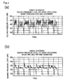
- FIG. 4(a) is a graph showing an outline of a sound pressure level of a squeak occurring in the claw 59 and the projection 58 in a case where both the rotator 12 and the sleeve 16 are formed of POM.
- FIG. 4(b) is a graph showing an outline of a sound pressure level of a squeak occurring in the claw 59 and the projection 58 in a case where both the rotator 12 and the sleeve 16 are formed of PBT.
- the sound pressure level of the squeak is lower in a case where both the rotator 12 and the sleeve 16 are formed of PBT than in a case where both the rotator 12 and the sleeve 16 are formed of POM.
- the steering roll connector 1 capable of suppressing occurrence of an abnormal noise even if a rotational force that pries the steering shaft is applied is provided.
- the rotator 12 is formed of POM
- the sub stator 11 is formed of PBT
- the stator 13 is formed of POM
- the sleeve 16 is formed of PBT.
- the abrasion resistance deteriorates in a case where sliding portions of the stator 13 and the rotator 12 or of the stator 13 and the sleeve 16 are formed of the same material, and the above-mentioned configuration applies to this case. Accordingly, the combination shown in SECOND MATERIAL of FIG. 3 is more excellent than the above-mentioned configuration.
- the steering roll connector 1 also includes a rotation sensor for detecting rotation, though not shown. Since the rotation sensor is arranged at a position in contact with the sleeve 16, it is preferable that the rotation sensor and the sleeve 16 are formed of different materials. For example, when the material of the rotation sensor is POM, PBT is adopted as the material of the sleeve 16, and thereby a noise can be reduced.
- the steering roll connector 1 of this embodiment includes the rotator 12, the sleeve 16, and the fixed casing 20.
- the rotator 12 includes the claw 59 and the inner cylindrical part 32, and is mounted to the steering shaft such that the rotator 12 is rotated integrally with the steering shaft inserted in the inner cylindrical part 32.
- the sleeve 16 includes the projection 58 connectable with the claw 59, and is mounted to the rotator 12 such that the sleeve 16 is rotated integrally with the rotator 12.
- the fixed casing 20 includes the outer cylindrical part 31, and is mounted to the steering column such that the fixed casing 20 does not follow the rotation of the steering shaft inserted in the outer cylindrical part 31 and such that the fixed casing 20 is in contact with the sleeve 16.
- a combination of materials of the claw 59 and the projection 58 is such that a squeak occurring when the claw 59 and the projection 58 are rubbed against each other is suppressed.
- the claw 59 and the projection 58 are fixed to each other by fitting of the claw 59 into the projection 58.
- the fixed casing 20 includes the stator 13 and the sub stator 11.
- the stator 13 includes the projection 48, and is fixed to the steering column such that the stator 13 does not follow the rotation of the steering shaft.
- the sub stator 11 includes the claw 49 connectable with the projection 48, and is mounted to the stator 13 such that the sub stator 11 is not rotated relative to the stator 13 and is arranged such that the sub stator 11 is in contact with the rotator 12.
- a combination of materials of the claw 49 and the projection 48 is such that a squeak occurring when the claw 49 and the projection 48 are rubbed against each other is suppressed.
- the claw 49 and the projection 48 are fixed to each other by fitting of one of them into the other.
- PBT and PBT are used as such a combination of materials that occurrence of a squeak is suppressed.
- a combination of PBT and POM is used as such a combination of materials that occurrence of a squeak is suppressed.
- the combination of the materials of the rotator 12 and the sleeve 16 is not limited to the above-described one, as long as occurrence of a squeak occurring when the rotator 12 and the sleeve 16 are rubbed against each other can be suppressed.
- a combination of PBT and POM may be adopted, or another engineering plastic may be adopted.
- the configuration for fixing the rotator 12 and the sleeve 16 to each other is not limited to the above-described configuration.
- a method may be adopted in which pin holes formed in the rotator 12 and the sleeve 16, respectively, are aligned and a joint pin is pushed into them.
Landscapes
- Engineering & Computer Science (AREA)
- Mechanical Engineering (AREA)
- Steering Controls (AREA)
- Power Steering Mechanism (AREA)
Abstract
Description
- The present invention relates to a rotary connector device. Particularly, the present invention relates to a configuration for reducing a noise occurring in a rotary connector device.
- Conventionally, various types of rotary connectors are known for electrically connecting a rotating side and a fixed side, such as a steering side and a vehicle body side of a vehicle, to each other.
Patent Document 1 discloses this type of rotary connector. - A rotary connector device of the
Patent Document 1 includes a first casing configured to be rotated integrally with a steering, and a second casing configured not to follow rotation of the steering. In these casings, a steering shaft (insert) can be inserted. These casings have an annular space formed therein. In the annular space, a flexible flat cable that electrically connects a steering side member and a vehicle body side member to each other is arranged. Hereinafter, configurations of the first casing and the second casing will be described with reference toFIG. 5 . - The first casing includes a rotator and a sleeve. The rotator is fixed to the steering shaft such that the rotator is rotatable integrally with the steering. The sleeve is fixed to the rotator by snap-fitting. In this configuration, when the steering shaft rotates, a force is transmitted from the steering shaft so that the rotator is rotated and accordingly the sleeve is also rotated.
- The second casing includes a stator and a sub stator. The stator is fixed to a steering column such that the stator does not follow rotation of the steering. The sub stator is fixed to the stator by snap-fitting. In this configuration, even when the steering shaft rotates, the stator and the sub stator are not rotated.
- In this configuration, the sleeve is in contact with the stator, and the rotator is in contact with the sub stator.
- Patent Document 1: Japanese Patent Application Laid-Open No.
2001-126836 - In the above-described conventional rotary connector device, it has been considered that a high friction does not occur in a contact portion between the sleeve and the stator and in a contact portion between the rotator and the sub stator so that the rotation of one does not apply any large force to the other.
- However, in the above-described rotary connector device, in a particular situation, an abnormal noise sometimes occurs when the steering is operated. The inventors of the present application, as a result of an intensive investigation of a cause thereof, have found that mainly two noises are caused from the rotary connector device (steering roll connector).
- A first noise results from a portion where the rotator and the sleeve are connected to each other. To be specific, not only a force in a rotation direction of the steering shaft but also a force in an axial direction of the steering shaft (in a direction pushing the steering in or in a direction pulling the steering) and a force in a radial direction of the steering shaft (in a direction moving the steering in translation), may be applied to the steering shaft. It is considered that this is because, for example, an operating force applied to the steering wheel by a driver is biased.
- If, in a state where a force other than the force in the rotation direction is applied to the steering shaft and the sleeve is pressed against the stator, a force is transmitted to the rotator so that the sleeve is rotated, a relatively high friction occurs between the stator and the sleeve. Due to this friction, the sleeve receives a force traveling against the rotation. Thus, a large force is applied to a connection portion between the rotator and the sleeve.
- As described above, if a force acts on the connection portion between the rotator and the sleeve, the positional relationship between a connection member (for example, a claw portion) at the rotator side and a connection member (for example, a receiving portion) at the sleeve side is slightly changed, and they are rubbed against each other. This causes a squeak that is the first noise. Particularly, the rotator and the sleeve are connected to each other by the snap-fitting which provides a weak fixing force, and therefore rubbing between members is likely to occur and the squeak tends to increase.
- A second noise results from a portion where the stator and the sub stator are connected to each other, and is caused on the same principle as the first noise. To be specific, in the same manner as described above, the force in the axial direction and the force in the radial direction are applied to the steering shaft, and the rotator is strongly pressed against the sub stator. This causes a relatively high friction between the rotator and the sub stator when the rotator is rotated. Due to this friction, a connection portion between the sub stator and the stator receives a large force. Thus, a connection member (for example, a claw portion) at the sub stator side and a connection member (for example, a receiving portion) at the stator side are rubbed against each other, to cause a noise (squeak).
- As mentioned above, it has been considered that a large force does not act between the sleeve and the stator and between the rotator and the sub stator. Therefore, a problem that the above-described two noises occur has not been assumed. Reduction of such noises is particularly demanded from the viewpoint of achieving the quietness in a vehicle, and the like.
- The present invention is made in view of the circumstances described above, and an object of the present invention is to provide a rotary connector device in which a noise during rotation is reduced even in a situation where a force other than a force in a rotation direction acts on an insert (for example, a steering shaft).
- The problem to be solved by the present invention is as described above, and next, means for solving the problem and effects thereof will be described.
- In an aspect of the present invention, a rotary connector device having the following configuration is provided. That is, the rotary connector device includes a first rotating member, a second rotating member, and a fixed member. The first rotating member includes a connecting portion and a cylindrical part, and is configured to be mounted such that the first rotating member is rotated integrally with an insert inserted in the cylindrical part. The second rotating member includes a connecting object portion connectable with the connecting portion, and is mounted to the first rotating member such that the second rotating member is rotated integrally with the first rotating member. The fixed member includes a second cylindrical part, and is mounted such that the fixed member does not follow rotation of the insert inserted in the second cylindrical part and such that the fixed member is in contact with the second rotating member. A combination of materials of the connecting portion and the connecting object portion is such that occurrence of a squeak caused when the connecting portion and the connecting object portion are rubbed against each other is suppressed.
- Accordingly, even when a force other than a force in a rotation direction is acting on the insert (for example, a steering shaft), a noise that occurs in the connecting portion and the connecting object portion during rotation of the first rotating member and the second rotating member can be reduced.
- In the rotary connector device, it is preferable that the connecting portion and the connecting object portion are fixed to each other by fitting of one of them into the other.
- That is, a configuration in which one is fitted into the other and thereby they are fixed to each other (snap-fitting) is excellent in operability in mounting, but a fixing force thereof is not so high and therefore rubbing between the connecting portion and the connecting object portion is likely to occur. Thus, the combination of materials mentioned above enables a more effective exertion of the effect of the present invention, that is, the suppression of occurrence of a squeak.
- The rotary connector device is preferably configured as follows. That is, the fixed member includes a first fixed member and a second fixed member. The first fixed member includes a second connecting portion, and is configured to be mounted such that the first fixed member does not follow rotation of the insert. The second fixed member includes a second connecting object portion connectable with the second connecting portion, and is mounted to the first fixed member such that the second fixed member is not rotated relative to the first fixed member and is arranged such that the second fixed member is in contact with the first rotating member. A combination of materials of the second connecting portion and the second connecting object portion is such that occurrence of a squeak caused when the second connecting portion and the second connecting object portion are rubbed against each other is suppressed.
- Accordingly, even when a force other than the force in the rotation direction is acting on the insert, a noise that occurs in the second connecting portion and the second connecting object portion during rotation of the first rotating member and the second rotating member can be reduced.
- In the rotary connector device, it is preferable that the second connecting portion and the second connecting object portion are fixed to each other by fitting of one of them into the other.
- That is, a configuration in which one is fitted into the other and thereby they are fixed to each other (snap-fitting) is excellent in operability in mounting, but a fixing force thereof is not so high and therefore rubbing between members is likely to occur. Thus, the combination of materials mentioned above enables a more effective exertion of the effect of the present invention, that is, the suppression of occurrence of a squeak.
- In the rotary connector device, it is preferable that the same material is used as such a combination of materials that occurrence of a squeak is suppressed.
- Accordingly, even when the same material is used, a material, such as polybutylene terephthalate, that is not likely to cause a squeak is used, and thereby the noise that occurs during the rotation of the first rotating member and the second rotating member in a situation where a force other than the force in the rotation direction acts on the insert can be reduced.
- In the rotary connector device, it is preferable that different materials are used as such a combination of materials that occurrence of a squeak is suppressed.
- That is, since it is generally known that a squeak occurring in a case of different materials is smaller than a squeak occurring in a case of the same kind of material, the above-mentioned configuration can further reduce the noise that occurs during the rotation of the first rotating member and the second rotating member in a situation where a force other than the force in the rotation direction acts on the insert.
-
- [
FIG. 1 ] A perspective view showing an overall configuration of a steering roll connector according to one embodiment of the present invention. - [
FIG. 2 ] An exploded perspective view of the steering roll connector. - [
FIG. 3 ] A table showing materials used in this embodiment. - [
FIG. 4 ] Graphs showing that a noise has been reduced as a result of changing the materials. - [
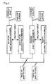
FIG. 5 ] A diagram for explaining the relationship among members included in the steering roll connector. - Next, an embodiment of the invention will be described.
FIG. 1 is a perspective view showing an overall configuration of asteering roll connector 1 according to one embodiment of the present invention, andFIG. 2 is an exploded perspective view of thesteering roll connector 1. - The
steering roll connector 1 serving as a rotary connector device shown inFIGS. 1 and2 includes acable housing 10 having a rotator (first rotating member) 12 and a fixed casing (fixed member) 20. The fixedcasing 20 is composed of a stator (first fixed member) 13 and a sub stator (second fixed member) 11. - The
stator 13 is fixed to a combination bracket switch (not shown) of a steering column. Aninsertion hole 19 in the shape of a through hole is formed at the center of thecable housing 10. A steering shaft supported on the steering column is inserted into theinsertion hole 19. Thestator 13 is rotatably mounted relative to the steering shaft. - As shown in
FIG. 2 and the like, thestator 13 has a projection (second connecting portion) 48, and thesub stator 11 has a claw (second connecting object portion) 49 formed at a position corresponding to theprojection 48. Theprojection 48 is hooked to the claw 49 (snap-fitting), and thereby thesub stator 11 is unrotatably mounted relative to thestator 13. Accordingly, not only thestator 13 but also thesub stator 11 is rotatable relative to the steering shaft. - On the other hand, the
rotator 12 is fixed to the steering shaft such that it is rotated integrally with the steering shaft. A steering wheel (rotation operation instrument) is fixed to the steering shaft. A lower surface of therotator 12 and an upper surface of thesub stator 11 are configured to be in contact with each other. - A sleeve (second rotating member) 16 is fixed to the
rotator 12. Thesleeve 16 has a projection (connecting object portion) 58, and therotator 12 has a claw (connecting portion) 59 formed at a position corresponding to theprojection 58. Theprojection 58 is hooked to theclaw 59, and thereby thesleeve 16 is unrotatably mounted relative to the rotator 12 (snap-fitting). Since it is necessary to pivotally support thestator 13 by sandwiching it between therotator 12 and thesleeve 16, therotator 12 and thesleeve 16 are formed as separate parts and they are fixed to each other by snap-fitting. An upper surface of thesleeve 16 and a lower surface of thestator 13 are configured to be in contact with each other. - As shown in
FIG. 2 , aninsertion slot 11a and anengagement recess 12a are formed in thesub stator 11 and therotator 12, respectively. A fixingpin 17 for stopping rotation can be inserted through theinsertion slot 11a. Anengagement projection 17a is formed in the fixingpin 17. The fixingpin 17 is inserted through theinsertion slot 11a and theengagement projection 17a is brought into engagement with theengagement recess 12a, and thereby therotator 12 can be locked against rotation relative to thesub stator 11 and thestator 13. - The fixing
pin 17 is temporarily attached at a time of manufacturing thesteering roll connector 1, in order to prevent the position of therotator 12 from being displaced from an intermediate position (a position intermediate between a position of therotator 12 having been rotated in a clockwise direction to the maximum and a position of therotator 12 having been rotated in a counterclockwise direction to the maximum) when thesteering roll connector 1 is mounted to a vehicle body. This improves an efficiency of an operation for assembling thesteering roll connector 1 to the vehicle body, and also prevents an error in the assembling. After thesteering roll connector 1 is appropriately mounted to the vehicle body, the fixingpin 17 is broken off at the root of a portion inserted through theinsertion slot 11a. Thereby, therotator 12 is made rotatable relative to thesub stator 11 and thestator 13. - A
first connector 41 is mounted to thestator 13, and asecond connector 42 is mounted to therotator 12. Thesecond connector 42 is rotated integrally with the rotation of therotator 12. Thefirst connector 41 is configured for connection with a wiring harness included in an electrical circuit at the vehicle body side. Thesecond connector 42 is configured for connection with cables, not shown, extending from electrical component (such as a horn switch and an airbag module) included in the steering wheel. Thefirst connector 41 and thesecond connector 42 are electrically connected to each other by a flexibleflat cable 14 which will be described later. - The
stator 13 and therotator 12 are opposed to each other in a direction of a rotation axis of the steering shaft. Therotator 12 and thestator 13 are arranged such that they connect an outercylindrical part 31 provided at the inner side of thesub stator 11 and an innercylindrical part 32 provided at the inner side of therotator 12 to each other. The innercylindrical part 32 is arranged inner than the outercylindrical part 31. The outercylindrical part 31 and the innercylindrical part 32 are arranged opposed to each other in a radial direction. In the above-described configuration, anaccommodation space 15 that is an annular space surrounded by thestator 13, therotator 12, the outercylindrical part 31, and the innercylindrical part 32, is formed. - As shown in
FIG. 2 , aretainer 25 and the flexibleflat cable 14 are accommodated within theaccommodation space 15. Theretainer 25 includes abase ring 26 and a plurality ofrotating rollers 27. - The
base ring 26 is configured as a plate-like member having an annular shape, and arranged adjacent to thestator 13. Thebase ring 26 is rotatable around an rotation axis of therotator 12. Therotating rollers 27 are arranged on one surface side of thebase ring 26 at regular intervals in a circumferential direction. Each of therotating rollers 27 is rotatable around an axis that is parallel to the rotation axis of therotator 12. The flexibleflat cable 14 is accommodated in theaccommodation space 15 in such a manner that it is wound on thebase ring 26. - To be specific, the flexible
flat cable 14 is drawn out from thefirst connector 41 into theaccommodation space 15, and a part of it is wound at the outer side of theretainer 25 and along an inner circumferential surface of thesub stator 11. Then, in the middle of the winding, the flexibleflat cable 14 reverses its direction while wrapping around one of the plurality ofrotating rollers 27. Thereafter, the flexibleflat cable 14 is wound at the inner side of theretainer 25 and along an outer circumferential surface of the innercylindrical part 32 of therotator 12, and finally is drawn out from theaccommodation space 15 and introduced into thesecond connector 42. - In this manner, within the
accommodation space 15, the flexibleflat cable 14 is wound with an appropriate length of loosening. This length of loosening changes as therotator 12 rotates relative to thestator 13. Theretainer 25 appropriately rotates so as to follow the change in the loosening length, and thereby enables the flexibleflat cable 14 to be always held in an aligned state within theaccommodation space 15. - Next, with reference to
FIG. 3 , a description will be given to a selection of materials made in this embodiment in order to reduce a noise that occurs during the rotation when a force other than a force in a rotation direction acts on the steering shaft.FIG. 3 is a table showing materials used in this embodiment. - Generally, it is known that a squeak occurring when resins are rubbed against each other is smaller in a case of rubbing between members of different materials than in a case of rubbing between members of the same material. One of the reasons therefor is that the phenomenon of a so-called chafing occurs at a contact surface between members in a case of the same material, while this chafing phenomenon is reduced in a case of different materials. It is also known that, even in a case where members of the same material are rubbed against each other, the magnitude of the squeak varies depending on the material.
- Considering the conditions described above, the inventors discussed PBT (polybutylene terephthalate) and POM (polyacetal) as the materials of the
rotator 12, thesub stator 11, thestator 13, and thesleeve 16 included in thesteering roll connector 1 of this embodiment. - In the following, a specific description will be given. The inventors of the present application firstly discussed a combination of POM and POM and a combination of PBT and PBT, as the materials of the rotator 12 (claw 59) and the sleeve 16 (projection 58) ("FIRST MATERIAL" and "SECOND MATERIAL" of
FIG. 3 ). As a result, it has been found that the squeak is reduced in the combination of PBT and PBT as compared with the combination of POM and POM. - The inventors of the present application also discussed a combination of PBT and PBT and a combination of a PBT and a POM, as a combination of materials of the sub stator 11 (claw 49) and the stator 13 (projection 48) ("FIRST MATERIAL" and "SECOND MATERIAL" of
FIG. 3 ). As a result, it has been found that the squeak is reduced in the combination of PBT and POM as compared with the combination of PBT and PBT. -
FIG. 4(a) is a graph showing an outline of a sound pressure level of a squeak occurring in theclaw 59 and theprojection 58 in a case where both therotator 12 and thesleeve 16 are formed of POM.FIG. 4(b) is a graph showing an outline of a sound pressure level of a squeak occurring in theclaw 59 and theprojection 58 in a case where both therotator 12 and thesleeve 16 are formed of PBT. - As seen from
FIG. 4 , the sound pressure level of the squeak is lower in a case where both therotator 12 and thesleeve 16 are formed of PBT than in a case where both therotator 12 and thesleeve 16 are formed of POM. - By selecting the materials of the resins in the above-described manner, the
steering roll connector 1 capable of suppressing occurrence of an abnormal noise even if a rotational force that pries the steering shaft is applied is provided. - From the viewpoint of noise reduction only, it is also conceivable that the
rotator 12 is formed of POM, thesub stator 11 is formed of PBT, thestator 13 is formed of POM, and thesleeve 16 is formed of PBT. However, it is known that the abrasion resistance deteriorates in a case where sliding portions of thestator 13 and therotator 12 or of thestator 13 and thesleeve 16 are formed of the same material, and the above-mentioned configuration applies to this case. Accordingly, the combination shown in SECOND MATERIAL ofFIG. 3 is more excellent than the above-mentioned configuration. - The
steering roll connector 1 also includes a rotation sensor for detecting rotation, though not shown. Since the rotation sensor is arranged at a position in contact with thesleeve 16, it is preferable that the rotation sensor and thesleeve 16 are formed of different materials. For example, when the material of the rotation sensor is POM, PBT is adopted as the material of thesleeve 16, and thereby a noise can be reduced. - As described above, the
steering roll connector 1 of this embodiment includes therotator 12, thesleeve 16, and the fixedcasing 20. Therotator 12 includes theclaw 59 and the innercylindrical part 32, and is mounted to the steering shaft such that therotator 12 is rotated integrally with the steering shaft inserted in the innercylindrical part 32. Thesleeve 16 includes theprojection 58 connectable with theclaw 59, and is mounted to therotator 12 such that thesleeve 16 is rotated integrally with therotator 12. The fixedcasing 20 includes the outercylindrical part 31, and is mounted to the steering column such that the fixedcasing 20 does not follow the rotation of the steering shaft inserted in the outercylindrical part 31 and such that the fixedcasing 20 is in contact with thesleeve 16. A combination of materials of theclaw 59 and theprojection 58 is such that a squeak occurring when theclaw 59 and theprojection 58 are rubbed against each other is suppressed. - Accordingly, when a force other than the force in the rotation direction acts on the steering shaft, the noise that occurs in the
claw 59 and theprojection 58 during the rotation of therotator 12 and thesleeve 16 can be reduced. - In the
steering roll connector 1 of this embodiment, theclaw 59 and theprojection 58 are fixed to each other by fitting of theclaw 59 into theprojection 58. - This can achieve a configuration with an excellent operability in mounting while suppressing occurrence of a squeak during the rotation of the
rotator 12 and thesleeve 16. - In the
steering roll connector 1 of this embodiment, the fixedcasing 20 includes thestator 13 and thesub stator 11. Thestator 13 includes theprojection 48, and is fixed to the steering column such that thestator 13 does not follow the rotation of the steering shaft. Thesub stator 11 includes theclaw 49 connectable with theprojection 48, and is mounted to thestator 13 such that thesub stator 11 is not rotated relative to thestator 13 and is arranged such that thesub stator 11 is in contact with therotator 12. A combination of materials of theclaw 49 and theprojection 48 is such that a squeak occurring when theclaw 49 and theprojection 48 are rubbed against each other is suppressed. - Accordingly, even when a force other than the force in the rotation direction is acting on the steering shaft, the noise that occurs in the
claw 49 and theprojection 48 during the rotation of therotator 12 and thesleeve 16 can be reduced. - In the
steering roll connector 1 of this embodiment, theclaw 49 and theprojection 48 are fixed to each other by fitting of one of them into the other. - This can achieve a configuration with an excellent operability in mounting while suppressing occurrence of a squeak during the rotation of the
rotator 12 and thesleeve 16. - In the
steering roll connector 1 of this embodiment, for therotator 12 and thesleeve 16, PBT and PBT are used as such a combination of materials that occurrence of a squeak is suppressed. - This, as compared with the combination of POM and POM, can reduce the noise that occurs during the rotation of the
rotator 12 and thesleeve 16 in a situation where a force other than the force in the rotation direction acts on the steering shaft. - In the
steering roll connector 1 of this embodiment, for thesub stator 11 and thestator 13, a combination of PBT and POM is used as such a combination of materials that occurrence of a squeak is suppressed. - This, as compared with the combination of PBT and PBT, can reduce the noise that occurs during the rotation of the
rotator 12 and thesleeve 16 in a situation where a force other than the force in the rotation direction acts on the steering shaft. - Although a preferred embodiment of the present invention has been described above, the above-described configuration may be modified, for example, as follows.
- The combination of the materials of the
rotator 12 and thesleeve 16 is not limited to the above-described one, as long as occurrence of a squeak occurring when therotator 12 and thesleeve 16 are rubbed against each other can be suppressed. For example, in a possible configuration, a combination of PBT and POM may be adopted, or another engineering plastic may be adopted. The same applies to the combination of the materials of thesub stator 11 and thestator 13. - The configuration for fixing the
rotator 12 and thesleeve 16 to each other is not limited to the above-described configuration. For example, a method may be adopted in which pin holes formed in therotator 12 and thesleeve 16, respectively, are aligned and a joint pin is pushed into them. The same applies to the configuration for fixing thesub stator 11 and thestator 13 to each other. -
1 steering roll connector (rotary connector device) 11 sub stator (second fixed member) 12 rotator (first rotating member) 13 stator (first fixed member) 16 sleeve (second rotating member) 20 fixed casing (fixed member) 31 outer cylindrical part (second cylindrical part) 32 inner cylindrical part (cylindrical part) 48 projection (second connecting portion) 49 claw (second connecting object portion) 58 projection (connecting object portion) 59 claw (connecting portion)
Claims (6)
- A rotary connector device comprising:a first rotating member including a connecting portion and a cylindrical part, the first rotating member being configured to be mounted such that the first rotating member is rotated integrally with an insert inserted in the cylindrical part;a second rotating member including a connecting object portion connectable with the connecting portion, the second rotating member being mounted to the first rotating member such that the second rotating member is rotated integrally with the first rotating member; anda fixed member including a second cylindrical part, the fixed member being mounted such that the fixed member does not follow rotation of the insert inserted in the second cylindrical part and such that the fixed member is in contact with the second rotating member,wherein a combination of materials of the connecting portion and the connecting object portion is such that occurrence of a squeak caused when the connecting portion and the connecting object portion are rubbed against each other is suppressed.
- The rotary connector device according to claim 1, wherein
the connecting portion and the connecting object portion are fixed to each other by fitting of one of them into the other. - The rotary connector device according to claim 1, wherein
the fixed member includes:a first fixed member including a second connecting portion, the first fixed member being configured to be mounted such that the first fixed member does not follow rotation of the insert; anda second fixed member including a second connecting object portion connectable with the second connecting portion, the second fixed member being mounted to the first fixed member such that the second fixed member is not rotated relative to the first fixed member and being arranged such that the second fixed member is in contact with the first rotating member,a combination of materials of the second connecting portion and the second connecting object portion is such that occurrence of a squeak caused when the second connecting portion and the second connecting object portion are rubbed against each other is suppressed. - The rotary connector device according to claim 3, wherein
the second connecting portion and the second connecting object portion are fixed to each other by fitting of one of them into the other. - The rotary connector device according to claim 1, wherein
the same material is used as such a combination of materials that occurrence of a squeak is suppressed. - The rotary connector device according to claim 1, wherein
different materials are used as such a combination of materials that occurrence of a squeak is suppressed.
Applications Claiming Priority (2)
| Application Number | Priority Date | Filing Date | Title |
|---|---|---|---|
| JP2010215401 | 2010-09-27 | ||
| PCT/JP2011/005435 WO2012042855A1 (en) | 2010-09-27 | 2011-09-27 | Rotary connector device |
Publications (3)
| Publication Number | Publication Date |
|---|---|
| EP2597734A1 true EP2597734A1 (en) | 2013-05-29 |
| EP2597734A4 EP2597734A4 (en) | 2013-12-11 |
| EP2597734B1 EP2597734B1 (en) | 2017-04-12 |
Family
ID=45892344
Family Applications (1)
| Application Number | Title | Priority Date | Filing Date |
|---|---|---|---|
| EP11828421.5A Active EP2597734B1 (en) | 2010-09-27 | 2011-09-27 | Rotary connector device |
Country Status (5)
| Country | Link |
|---|---|
| US (1) | US8529272B2 (en) |
| EP (1) | EP2597734B1 (en) |
| JP (1) | JP5019662B2 (en) |
| CN (1) | CN103081257B (en) |
| WO (1) | WO2012042855A1 (en) |
Families Citing this family (10)
| Publication number | Priority date | Publication date | Assignee | Title |
|---|---|---|---|---|
| JP5347986B2 (en) * | 2010-01-19 | 2013-11-20 | 株式会社リコー | Rotation detecting device, paper feeding device and image forming device |
| EP2542391B1 (en) * | 2010-03-02 | 2014-06-25 | ABB Research Ltd. | A system for electrically connecting a tool to a robot wrist and a method therefor |
| JP5117529B2 (en) * | 2010-03-30 | 2013-01-16 | 古河電気工業株式会社 | Rotating connector device |
| KR101591320B1 (en) * | 2013-01-15 | 2016-02-03 | 후루카와 덴키 고교 가부시키가이샤 | Rotary connector with sensor assembled thereto |
| US9627832B2 (en) | 2014-08-04 | 2017-04-18 | American Furukawa, Inc. | Lock member for a rotary connector device |
| US9413128B2 (en) * | 2014-09-04 | 2016-08-09 | Htc Corporation | Connector module having a rotating element disposed within and rotatable relative to a case |
| KR102241323B1 (en) * | 2017-02-10 | 2021-04-16 | 후루카와 덴키 고교 가부시키가이샤 | Rotating connector device |
| JP7354103B2 (en) * | 2018-06-11 | 2023-10-02 | 古河電気工業株式会社 | Rotary connector device and fixed body of the rotary connector device |
| WO2020121741A1 (en) * | 2018-12-13 | 2020-06-18 | 古河電気工業株式会社 | Rotary connector device |
| JP7680423B2 (en) * | 2020-03-25 | 2025-05-20 | 古河電気工業株式会社 | Rotating Connector Device |
Family Cites Families (8)
| Publication number | Priority date | Publication date | Assignee | Title |
|---|---|---|---|---|
| JP3676146B2 (en) | 1999-10-22 | 2005-07-27 | 古河電気工業株式会社 | Rotating connector |
| US6854977B2 (en) * | 2002-09-13 | 2005-02-15 | Trw Inc. | Steering wheel rotary connector |
| US6780032B2 (en) * | 2002-10-07 | 2004-08-24 | Tyco Electronics Corporation | Loop back clockspring connector having high current capacity |
| JP2006120512A (en) * | 2004-10-22 | 2006-05-11 | Alps Electric Co Ltd | Rotary connector |
| US7452224B1 (en) * | 2007-07-06 | 2008-11-18 | Bourns, Inc. | Clockspring sensor with locking clip and centering mechanism |
| JP4491013B2 (en) * | 2007-12-17 | 2010-06-30 | アルプス電気株式会社 | Rotating connector |
| DE102008057588A1 (en) * | 2008-11-15 | 2010-05-20 | Leopold Kostal Gmbh & Co. Kg | Electric device |
| JP4974195B2 (en) * | 2010-10-20 | 2012-07-11 | 古河電気工業株式会社 | Rotating connector device |
-
2011
- 2011-09-27 JP JP2012507519A patent/JP5019662B2/en active Active
- 2011-09-27 US US13/809,588 patent/US8529272B2/en active Active
- 2011-09-27 WO PCT/JP2011/005435 patent/WO2012042855A1/en not_active Ceased
- 2011-09-27 CN CN201180041648.8A patent/CN103081257B/en active Active
- 2011-09-27 EP EP11828421.5A patent/EP2597734B1/en active Active
Also Published As
| Publication number | Publication date |
|---|---|
| EP2597734B1 (en) | 2017-04-12 |
| CN103081257B (en) | 2015-11-25 |
| US8529272B2 (en) | 2013-09-10 |
| JPWO2012042855A1 (en) | 2014-02-06 |
| CN103081257A (en) | 2013-05-01 |
| JP5019662B2 (en) | 2012-09-05 |
| WO2012042855A1 (en) | 2012-04-05 |
| US20130115785A1 (en) | 2013-05-09 |
| EP2597734A4 (en) | 2013-12-11 |
Similar Documents
| Publication | Publication Date | Title |
|---|---|---|
| US8529272B2 (en) | Rotary connector device | |
| CN102822011B (en) | Rotary connector unit | |
| US8758024B2 (en) | Rotary connector device | |
| EP2685571B1 (en) | Rotatable connector device | |
| US9070496B2 (en) | Rotatable connector device | |
| JP4974195B2 (en) | Rotating connector device | |
| JP2011207402A5 (en) | ||
| KR20120105358A (en) | Rotary connector | |
| US20090317995A1 (en) | Rotary Connector Device | |
| WO2011122471A1 (en) | Rotary connector device | |
| CN103262365B (en) | Rotary connector device | |
| JP2007213958A (en) | Rotating connector device | |
| US12334695B2 (en) | Rotary connector device | |
| JPH08180950A (en) | Electrical connection device between steering wheel and steering column | |
| JPH08301126A (en) | Coupling structure of steering wheel and rotary connector | |
| JP2010009849A (en) | Rotary connector device | |
| JP5871436B2 (en) | Rotating connector device | |
| JP3296662B2 (en) | Rotary connector with temporary fixing mechanism | |
| US12157445B2 (en) | Actuator for electronic parking brake | |
| JP4191148B2 (en) | Spiral cable device | |
| KR20250065649A (en) | Rotating connector devices and vehicle-mounted devices |
Legal Events
| Date | Code | Title | Description |
|---|---|---|---|
| PUAI | Public reference made under article 153(3) epc to a published international application that has entered the european phase |
Free format text: ORIGINAL CODE: 0009012 |
|
| 17P | Request for examination filed |
Effective date: 20130118 |
|
| AK | Designated contracting states |
Kind code of ref document: A1 Designated state(s): AL AT BE BG CH CY CZ DE DK EE ES FI FR GB GR HR HU IE IS IT LI LT LU LV MC MK MT NL NO PL PT RO RS SE SI SK SM TR |
|
| RIC1 | Information provided on ipc code assigned before grant |
Ipc: H01R 35/04 20060101AFI20131031BHEP Ipc: B60R 16/027 20060101ALI20131031BHEP Ipc: B62D 1/04 20060101ALI20131031BHEP |
|
| A4 | Supplementary search report drawn up and despatched |
Effective date: 20131113 |
|
| DAX | Request for extension of the european patent (deleted) | ||
| 17Q | First examination report despatched |
Effective date: 20160321 |
|
| GRAP | Despatch of communication of intention to grant a patent |
Free format text: ORIGINAL CODE: EPIDOSNIGR1 |
|
| STAA | Information on the status of an ep patent application or granted ep patent |
Free format text: STATUS: GRANT OF PATENT IS INTENDED |
|
| INTG | Intention to grant announced |
Effective date: 20161104 |
|
| GRAS | Grant fee paid |
Free format text: ORIGINAL CODE: EPIDOSNIGR3 |
|
| GRAA | (expected) grant |
Free format text: ORIGINAL CODE: 0009210 |
|
| STAA | Information on the status of an ep patent application or granted ep patent |
Free format text: STATUS: THE PATENT HAS BEEN GRANTED |
|
| AK | Designated contracting states |
Kind code of ref document: B1 Designated state(s): AL AT BE BG CH CY CZ DE DK EE ES FI FR GB GR HR HU IE IS IT LI LT LU LV MC MK MT NL NO PL PT RO RS SE SI SK SM TR |
|
| REG | Reference to a national code |
Ref country code: GB Ref legal event code: FG4D |
|
| REG | Reference to a national code |
Ref country code: CH Ref legal event code: EP |
|
| REG | Reference to a national code |
Ref country code: IE Ref legal event code: FG4D |
|
| REG | Reference to a national code |
Ref country code: AT Ref legal event code: REF Ref document number: 884741 Country of ref document: AT Kind code of ref document: T Effective date: 20170515 |
|
| REG | Reference to a national code |
Ref country code: DE Ref legal event code: R096 Ref document number: 602011036988 Country of ref document: DE |
|
| REG | Reference to a national code |
Ref country code: NL Ref legal event code: MP Effective date: 20170412 |
|
| REG | Reference to a national code |
Ref country code: LT Ref legal event code: MG4D |
|
| REG | Reference to a national code |
Ref country code: AT Ref legal event code: MK05 Ref document number: 884741 Country of ref document: AT Kind code of ref document: T Effective date: 20170412 |
|
| PG25 | Lapsed in a contracting state [announced via postgrant information from national office to epo] |
Ref country code: NL Free format text: LAPSE BECAUSE OF FAILURE TO SUBMIT A TRANSLATION OF THE DESCRIPTION OR TO PAY THE FEE WITHIN THE PRESCRIBED TIME-LIMIT Effective date: 20170412 |
|
| PG25 | Lapsed in a contracting state [announced via postgrant information from national office to epo] |
Ref country code: GR Free format text: LAPSE BECAUSE OF FAILURE TO SUBMIT A TRANSLATION OF THE DESCRIPTION OR TO PAY THE FEE WITHIN THE PRESCRIBED TIME-LIMIT Effective date: 20170713 Ref country code: LT Free format text: LAPSE BECAUSE OF FAILURE TO SUBMIT A TRANSLATION OF THE DESCRIPTION OR TO PAY THE FEE WITHIN THE PRESCRIBED TIME-LIMIT Effective date: 20170412 Ref country code: AT Free format text: LAPSE BECAUSE OF FAILURE TO SUBMIT A TRANSLATION OF THE DESCRIPTION OR TO PAY THE FEE WITHIN THE PRESCRIBED TIME-LIMIT Effective date: 20170412 Ref country code: FI Free format text: LAPSE BECAUSE OF FAILURE TO SUBMIT A TRANSLATION OF THE DESCRIPTION OR TO PAY THE FEE WITHIN THE PRESCRIBED TIME-LIMIT Effective date: 20170412 Ref country code: HR Free format text: LAPSE BECAUSE OF FAILURE TO SUBMIT A TRANSLATION OF THE DESCRIPTION OR TO PAY THE FEE WITHIN THE PRESCRIBED TIME-LIMIT Effective date: 20170412 Ref country code: NO Free format text: LAPSE BECAUSE OF FAILURE TO SUBMIT A TRANSLATION OF THE DESCRIPTION OR TO PAY THE FEE WITHIN THE PRESCRIBED TIME-LIMIT Effective date: 20170712 Ref country code: ES Free format text: LAPSE BECAUSE OF FAILURE TO SUBMIT A TRANSLATION OF THE DESCRIPTION OR TO PAY THE FEE WITHIN THE PRESCRIBED TIME-LIMIT Effective date: 20170412 |
|
| PG25 | Lapsed in a contracting state [announced via postgrant information from national office to epo] |
Ref country code: IS Free format text: LAPSE BECAUSE OF FAILURE TO SUBMIT A TRANSLATION OF THE DESCRIPTION OR TO PAY THE FEE WITHIN THE PRESCRIBED TIME-LIMIT Effective date: 20170812 Ref country code: SE Free format text: LAPSE BECAUSE OF FAILURE TO SUBMIT A TRANSLATION OF THE DESCRIPTION OR TO PAY THE FEE WITHIN THE PRESCRIBED TIME-LIMIT Effective date: 20170412 Ref country code: PL Free format text: LAPSE BECAUSE OF FAILURE TO SUBMIT A TRANSLATION OF THE DESCRIPTION OR TO PAY THE FEE WITHIN THE PRESCRIBED TIME-LIMIT Effective date: 20170412 Ref country code: RS Free format text: LAPSE BECAUSE OF FAILURE TO SUBMIT A TRANSLATION OF THE DESCRIPTION OR TO PAY THE FEE WITHIN THE PRESCRIBED TIME-LIMIT Effective date: 20170412 Ref country code: LV Free format text: LAPSE BECAUSE OF FAILURE TO SUBMIT A TRANSLATION OF THE DESCRIPTION OR TO PAY THE FEE WITHIN THE PRESCRIBED TIME-LIMIT Effective date: 20170412 Ref country code: BG Free format text: LAPSE BECAUSE OF FAILURE TO SUBMIT A TRANSLATION OF THE DESCRIPTION OR TO PAY THE FEE WITHIN THE PRESCRIBED TIME-LIMIT Effective date: 20170712 |
|
| REG | Reference to a national code |
Ref country code: DE Ref legal event code: R097 Ref document number: 602011036988 Country of ref document: DE |
|
| PG25 | Lapsed in a contracting state [announced via postgrant information from national office to epo] |
Ref country code: RO Free format text: LAPSE BECAUSE OF FAILURE TO SUBMIT A TRANSLATION OF THE DESCRIPTION OR TO PAY THE FEE WITHIN THE PRESCRIBED TIME-LIMIT Effective date: 20170412 Ref country code: SK Free format text: LAPSE BECAUSE OF FAILURE TO SUBMIT A TRANSLATION OF THE DESCRIPTION OR TO PAY THE FEE WITHIN THE PRESCRIBED TIME-LIMIT Effective date: 20170412 Ref country code: CZ Free format text: LAPSE BECAUSE OF FAILURE TO SUBMIT A TRANSLATION OF THE DESCRIPTION OR TO PAY THE FEE WITHIN THE PRESCRIBED TIME-LIMIT Effective date: 20170412 Ref country code: DK Free format text: LAPSE BECAUSE OF FAILURE TO SUBMIT A TRANSLATION OF THE DESCRIPTION OR TO PAY THE FEE WITHIN THE PRESCRIBED TIME-LIMIT Effective date: 20170412 Ref country code: EE Free format text: LAPSE BECAUSE OF FAILURE TO SUBMIT A TRANSLATION OF THE DESCRIPTION OR TO PAY THE FEE WITHIN THE PRESCRIBED TIME-LIMIT Effective date: 20170412 |
|
| PLBE | No opposition filed within time limit |
Free format text: ORIGINAL CODE: 0009261 |
|
| STAA | Information on the status of an ep patent application or granted ep patent |
Free format text: STATUS: NO OPPOSITION FILED WITHIN TIME LIMIT |
|
| PG25 | Lapsed in a contracting state [announced via postgrant information from national office to epo] |
Ref country code: SM Free format text: LAPSE BECAUSE OF FAILURE TO SUBMIT A TRANSLATION OF THE DESCRIPTION OR TO PAY THE FEE WITHIN THE PRESCRIBED TIME-LIMIT Effective date: 20170412 Ref country code: IT Free format text: LAPSE BECAUSE OF FAILURE TO SUBMIT A TRANSLATION OF THE DESCRIPTION OR TO PAY THE FEE WITHIN THE PRESCRIBED TIME-LIMIT Effective date: 20170412 |
|
| 26N | No opposition filed |
Effective date: 20180115 |
|
| REG | Reference to a national code |
Ref country code: CH Ref legal event code: PL |
|
| GBPC | Gb: european patent ceased through non-payment of renewal fee |
Effective date: 20170927 |
|
| PG25 | Lapsed in a contracting state [announced via postgrant information from national office to epo] |
Ref country code: SI Free format text: LAPSE BECAUSE OF FAILURE TO SUBMIT A TRANSLATION OF THE DESCRIPTION OR TO PAY THE FEE WITHIN THE PRESCRIBED TIME-LIMIT Effective date: 20170412 Ref country code: MC Free format text: LAPSE BECAUSE OF FAILURE TO SUBMIT A TRANSLATION OF THE DESCRIPTION OR TO PAY THE FEE WITHIN THE PRESCRIBED TIME-LIMIT Effective date: 20170412 |
|
| REG | Reference to a national code |
Ref country code: IE Ref legal event code: MM4A |
|
| REG | Reference to a national code |
Ref country code: BE Ref legal event code: MM Effective date: 20170930 |
|
| PG25 | Lapsed in a contracting state [announced via postgrant information from national office to epo] |
Ref country code: LU Free format text: LAPSE BECAUSE OF NON-PAYMENT OF DUE FEES Effective date: 20170927 |
|
| REG | Reference to a national code |
Ref country code: FR Ref legal event code: ST Effective date: 20180531 |
|
| PG25 | Lapsed in a contracting state [announced via postgrant information from national office to epo] |
Ref country code: CH Free format text: LAPSE BECAUSE OF NON-PAYMENT OF DUE FEES Effective date: 20170930 Ref country code: LI Free format text: LAPSE BECAUSE OF NON-PAYMENT OF DUE FEES Effective date: 20170930 Ref country code: IE Free format text: LAPSE BECAUSE OF NON-PAYMENT OF DUE FEES Effective date: 20170927 Ref country code: GB Free format text: LAPSE BECAUSE OF NON-PAYMENT OF DUE FEES Effective date: 20170927 |
|
| PG25 | Lapsed in a contracting state [announced via postgrant information from national office to epo] |
Ref country code: FR Free format text: LAPSE BECAUSE OF NON-PAYMENT OF DUE FEES Effective date: 20171002 Ref country code: BE Free format text: LAPSE BECAUSE OF NON-PAYMENT OF DUE FEES Effective date: 20170930 |
|
| PG25 | Lapsed in a contracting state [announced via postgrant information from national office to epo] |
Ref country code: MT Free format text: LAPSE BECAUSE OF NON-PAYMENT OF DUE FEES Effective date: 20170927 |
|
| PG25 | Lapsed in a contracting state [announced via postgrant information from national office to epo] |
Ref country code: HU Free format text: LAPSE BECAUSE OF FAILURE TO SUBMIT A TRANSLATION OF THE DESCRIPTION OR TO PAY THE FEE WITHIN THE PRESCRIBED TIME-LIMIT; INVALID AB INITIO Effective date: 20110927 |
|
| PG25 | Lapsed in a contracting state [announced via postgrant information from national office to epo] |
Ref country code: CY Free format text: LAPSE BECAUSE OF NON-PAYMENT OF DUE FEES Effective date: 20170412 |
|
| PG25 | Lapsed in a contracting state [announced via postgrant information from national office to epo] |
Ref country code: MK Free format text: LAPSE BECAUSE OF FAILURE TO SUBMIT A TRANSLATION OF THE DESCRIPTION OR TO PAY THE FEE WITHIN THE PRESCRIBED TIME-LIMIT Effective date: 20170412 |
|
| PG25 | Lapsed in a contracting state [announced via postgrant information from national office to epo] |
Ref country code: TR Free format text: LAPSE BECAUSE OF FAILURE TO SUBMIT A TRANSLATION OF THE DESCRIPTION OR TO PAY THE FEE WITHIN THE PRESCRIBED TIME-LIMIT Effective date: 20170412 |
|
| PG25 | Lapsed in a contracting state [announced via postgrant information from national office to epo] |
Ref country code: PT Free format text: LAPSE BECAUSE OF FAILURE TO SUBMIT A TRANSLATION OF THE DESCRIPTION OR TO PAY THE FEE WITHIN THE PRESCRIBED TIME-LIMIT Effective date: 20170412 |
|
| PG25 | Lapsed in a contracting state [announced via postgrant information from national office to epo] |
Ref country code: AL Free format text: LAPSE BECAUSE OF FAILURE TO SUBMIT A TRANSLATION OF THE DESCRIPTION OR TO PAY THE FEE WITHIN THE PRESCRIBED TIME-LIMIT Effective date: 20170412 |
|
| P01 | Opt-out of the competence of the unified patent court (upc) registered |
Effective date: 20230512 |
|
| PGFP | Annual fee paid to national office [announced via postgrant information from national office to epo] |
Ref country code: DE Payment date: 20250805 Year of fee payment: 15 |