EP2597700A1 - Battery pack - Google Patents
Battery pack Download PDFInfo
- Publication number
- EP2597700A1 EP2597700A1 EP20120187560 EP12187560A EP2597700A1 EP 2597700 A1 EP2597700 A1 EP 2597700A1 EP 20120187560 EP20120187560 EP 20120187560 EP 12187560 A EP12187560 A EP 12187560A EP 2597700 A1 EP2597700 A1 EP 2597700A1
- Authority
- EP
- European Patent Office
- Prior art keywords
- battery pack
- battery
- module
- hole
- housing
- Prior art date
- Legal status (The legal status is an assumption and is not a legal conclusion. Google has not performed a legal analysis and makes no representation as to the accuracy of the status listed.)
- Granted
Links
Images



Classifications
-
- H—ELECTRICITY
- H01—ELECTRIC ELEMENTS
- H01M—PROCESSES OR MEANS, e.g. BATTERIES, FOR THE DIRECT CONVERSION OF CHEMICAL ENERGY INTO ELECTRICAL ENERGY
- H01M10/00—Secondary cells; Manufacture thereof
- H01M10/60—Heating or cooling; Temperature control
- H01M10/65—Means for temperature control structurally associated with the cells
- H01M10/657—Means for temperature control structurally associated with the cells by electric or electromagnetic means
- H01M10/6572—Peltier elements or thermoelectric devices
-
- H—ELECTRICITY
- H01—ELECTRIC ELEMENTS
- H01M—PROCESSES OR MEANS, e.g. BATTERIES, FOR THE DIRECT CONVERSION OF CHEMICAL ENERGY INTO ELECTRICAL ENERGY
- H01M10/00—Secondary cells; Manufacture thereof
- H01M10/60—Heating or cooling; Temperature control
- H01M10/62—Heating or cooling; Temperature control specially adapted for specific applications
- H01M10/625—Vehicles
-
- H—ELECTRICITY
- H01—ELECTRIC ELEMENTS
- H01M—PROCESSES OR MEANS, e.g. BATTERIES, FOR THE DIRECT CONVERSION OF CHEMICAL ENERGY INTO ELECTRICAL ENERGY
- H01M10/00—Secondary cells; Manufacture thereof
- H01M10/60—Heating or cooling; Temperature control
- H01M10/61—Types of temperature control
- H01M10/613—Cooling or keeping cold
-
- H—ELECTRICITY
- H01—ELECTRIC ELEMENTS
- H01M—PROCESSES OR MEANS, e.g. BATTERIES, FOR THE DIRECT CONVERSION OF CHEMICAL ENERGY INTO ELECTRICAL ENERGY
- H01M50/00—Constructional details or processes of manufacture of the non-active parts of electrochemical cells other than fuel cells, e.g. hybrid cells
- H01M50/20—Mountings; Secondary casings or frames; Racks, modules or packs; Suspension devices; Shock absorbers; Transport or carrying devices; Holders
- H01M50/204—Racks, modules or packs for multiple batteries or multiple cells
-
- H—ELECTRICITY
- H01—ELECTRIC ELEMENTS
- H01M—PROCESSES OR MEANS, e.g. BATTERIES, FOR THE DIRECT CONVERSION OF CHEMICAL ENERGY INTO ELECTRICAL ENERGY
- H01M50/00—Constructional details or processes of manufacture of the non-active parts of electrochemical cells other than fuel cells, e.g. hybrid cells
- H01M50/20—Mountings; Secondary casings or frames; Racks, modules or packs; Suspension devices; Shock absorbers; Transport or carrying devices; Holders
- H01M50/233—Mountings; Secondary casings or frames; Racks, modules or packs; Suspension devices; Shock absorbers; Transport or carrying devices; Holders characterised by physical properties of casings or racks, e.g. dimensions
- H01M50/242—Mountings; Secondary casings or frames; Racks, modules or packs; Suspension devices; Shock absorbers; Transport or carrying devices; Holders characterised by physical properties of casings or racks, e.g. dimensions adapted for protecting batteries against vibrations, collision impact or swelling
-
- H—ELECTRICITY
- H01—ELECTRIC ELEMENTS
- H01M—PROCESSES OR MEANS, e.g. BATTERIES, FOR THE DIRECT CONVERSION OF CHEMICAL ENERGY INTO ELECTRICAL ENERGY
- H01M50/00—Constructional details or processes of manufacture of the non-active parts of electrochemical cells other than fuel cells, e.g. hybrid cells
- H01M50/20—Mountings; Secondary casings or frames; Racks, modules or packs; Suspension devices; Shock absorbers; Transport or carrying devices; Holders
- H01M50/244—Secondary casings; Racks; Suspension devices; Carrying devices; Holders characterised by their mounting method
-
- H—ELECTRICITY
- H01—ELECTRIC ELEMENTS
- H01M—PROCESSES OR MEANS, e.g. BATTERIES, FOR THE DIRECT CONVERSION OF CHEMICAL ENERGY INTO ELECTRICAL ENERGY
- H01M50/00—Constructional details or processes of manufacture of the non-active parts of electrochemical cells other than fuel cells, e.g. hybrid cells
- H01M50/20—Mountings; Secondary casings or frames; Racks, modules or packs; Suspension devices; Shock absorbers; Transport or carrying devices; Holders
- H01M50/258—Modular batteries; Casings provided with means for assembling
-
- H—ELECTRICITY
- H01—ELECTRIC ELEMENTS
- H01M—PROCESSES OR MEANS, e.g. BATTERIES, FOR THE DIRECT CONVERSION OF CHEMICAL ENERGY INTO ELECTRICAL ENERGY
- H01M50/00—Constructional details or processes of manufacture of the non-active parts of electrochemical cells other than fuel cells, e.g. hybrid cells
- H01M50/20—Mountings; Secondary casings or frames; Racks, modules or packs; Suspension devices; Shock absorbers; Transport or carrying devices; Holders
- H01M50/262—Mountings; Secondary casings or frames; Racks, modules or packs; Suspension devices; Shock absorbers; Transport or carrying devices; Holders with fastening means, e.g. locks
-
- H—ELECTRICITY
- H01—ELECTRIC ELEMENTS
- H01M—PROCESSES OR MEANS, e.g. BATTERIES, FOR THE DIRECT CONVERSION OF CHEMICAL ENERGY INTO ELECTRICAL ENERGY
- H01M50/00—Constructional details or processes of manufacture of the non-active parts of electrochemical cells other than fuel cells, e.g. hybrid cells
- H01M50/30—Arrangements for facilitating escape of gases
-
- H—ELECTRICITY
- H01—ELECTRIC ELEMENTS
- H01M—PROCESSES OR MEANS, e.g. BATTERIES, FOR THE DIRECT CONVERSION OF CHEMICAL ENERGY INTO ELECTRICAL ENERGY
- H01M50/00—Constructional details or processes of manufacture of the non-active parts of electrochemical cells other than fuel cells, e.g. hybrid cells
- H01M50/60—Arrangements or processes for filling or topping-up with liquids; Arrangements or processes for draining liquids from casings
-
- H—ELECTRICITY
- H01—ELECTRIC ELEMENTS
- H01M—PROCESSES OR MEANS, e.g. BATTERIES, FOR THE DIRECT CONVERSION OF CHEMICAL ENERGY INTO ELECTRICAL ENERGY
- H01M10/00—Secondary cells; Manufacture thereof
- H01M10/60—Heating or cooling; Temperature control
- H01M10/65—Means for temperature control structurally associated with the cells
- H01M10/656—Means for temperature control structurally associated with the cells characterised by the type of heat-exchange fluid
- H01M10/6561—Gases
- H01M10/6563—Gases with forced flow, e.g. by blowers
-
- H—ELECTRICITY
- H01—ELECTRIC ELEMENTS
- H01M—PROCESSES OR MEANS, e.g. BATTERIES, FOR THE DIRECT CONVERSION OF CHEMICAL ENERGY INTO ELECTRICAL ENERGY
- H01M10/00—Secondary cells; Manufacture thereof
- H01M10/60—Heating or cooling; Temperature control
- H01M10/66—Heat-exchange relationships between the cells and other systems, e.g. central heating systems or fuel cells
- H01M10/663—Heat-exchange relationships between the cells and other systems, e.g. central heating systems or fuel cells the system being an air-conditioner or an engine
-
- H—ELECTRICITY
- H01—ELECTRIC ELEMENTS
- H01M—PROCESSES OR MEANS, e.g. BATTERIES, FOR THE DIRECT CONVERSION OF CHEMICAL ENERGY INTO ELECTRICAL ENERGY
- H01M2220/00—Batteries for particular applications
- H01M2220/20—Batteries in motive systems, e.g. vehicle, ship, plane
-
- H—ELECTRICITY
- H01—ELECTRIC ELEMENTS
- H01M—PROCESSES OR MEANS, e.g. BATTERIES, FOR THE DIRECT CONVERSION OF CHEMICAL ENERGY INTO ELECTRICAL ENERGY
- H01M50/00—Constructional details or processes of manufacture of the non-active parts of electrochemical cells other than fuel cells, e.g. hybrid cells
- H01M50/20—Mountings; Secondary casings or frames; Racks, modules or packs; Suspension devices; Shock absorbers; Transport or carrying devices; Holders
- H01M50/271—Lids or covers for the racks or secondary casings
-
- H—ELECTRICITY
- H01—ELECTRIC ELEMENTS
- H01M—PROCESSES OR MEANS, e.g. BATTERIES, FOR THE DIRECT CONVERSION OF CHEMICAL ENERGY INTO ELECTRICAL ENERGY
- H01M50/00—Constructional details or processes of manufacture of the non-active parts of electrochemical cells other than fuel cells, e.g. hybrid cells
- H01M50/20—Mountings; Secondary casings or frames; Racks, modules or packs; Suspension devices; Shock absorbers; Transport or carrying devices; Holders
- H01M50/289—Mountings; Secondary casings or frames; Racks, modules or packs; Suspension devices; Shock absorbers; Transport or carrying devices; Holders characterised by spacing elements or positioning means within frames, racks or packs
-
- Y—GENERAL TAGGING OF NEW TECHNOLOGICAL DEVELOPMENTS; GENERAL TAGGING OF CROSS-SECTIONAL TECHNOLOGIES SPANNING OVER SEVERAL SECTIONS OF THE IPC; TECHNICAL SUBJECTS COVERED BY FORMER USPC CROSS-REFERENCE ART COLLECTIONS [XRACs] AND DIGESTS
- Y02—TECHNOLOGIES OR APPLICATIONS FOR MITIGATION OR ADAPTATION AGAINST CLIMATE CHANGE
- Y02E—REDUCTION OF GREENHOUSE GAS [GHG] EMISSIONS, RELATED TO ENERGY GENERATION, TRANSMISSION OR DISTRIBUTION
- Y02E60/00—Enabling technologies; Technologies with a potential or indirect contribution to GHG emissions mitigation
- Y02E60/10—Energy storage using batteries
Definitions
- the invention relates to a battery pack.
- a battery cell is used as an energy source for a mobile unit, an electrical vehicle, hybrid cars and the like and different types of battery cells may be used depending on a type of an external device to which they are applied.
- the battery module may maximize an output voltage or an output current based on the number of the built-in battery
- a plurality of battery modules may be electrically connected to assemble a battery pack.
- the battery pack of high-capacity has a problem that a large amount of heat is generated in the process of the charge/discharge.
- a cooling system can be used with the high output and high capacity battery pack and the cooling system serves to decrease an internal temperature of the battery pack by providing a cooling medium such as air and the like to one side of the battery pack and discharging the air from the other side of a battery pack.
- the present invention provides a battery pack wherein water generated by air having high humidity flown in the inner portion of the battery pack is easily dumped through a first hole formed at a slope or slope portion of a lower housing and an end of a slope.
- a battery pack includes at least one battery module comprising a plurality of battery cells; and a housing accommodating the at least one battery module and having an inlet port at a first side thereof and an outlet port at a second side thereof opposite the first side, the housing having a bottom surface or plate that has a slope and a first hole at an end of the slope.
- the first hole may be arranged at a lower end of the sloped bottom surface or plate.
- the slope or slope portion is inclined downwardly in a direction from the inlet port towards the outlet port.
- the slope portion is preferably inclined downwardly from the inlet port and from the outlet port towards an area between the inlet port and the outlet port.
- the slope portion and/or the slope may be inclined downwardly or sloped towards a longitudinal side of the housing, the longitudinal side extending between first and the second side.
- a cushioning member is located between the bottom surface or plate of the housing and the battery module. The slope or slope portion and the first hole are formed in a direction from the inlet port to the outlet portion prior to or after the formation of the cushioning member.
- the slope portion and the first hole are formed between the inlet port and the cushioning member or the slope portion and the first hole are formed between the cushioning member and the outlet port. Further, in one embodiment, the slope or slope portion extends from a first end of battery module on which the inlet port is formed to a second end of the battery module on which the outlet port is formed.
- the battery pack includes a module supporting portion between the bottom surface or plate and the at least one battery module, and optionally a module fastening hole for fastening the at least one battery module may be formed on the module supporting portion.
- the battery pack includes a module seating portion between the bottom surface or plate of the housing and the at least one battery module, and the module seating portion may optionally have at least one second hole.
- an opening and closing means such as a valve
- the battery pack may include a pressure sensing section for controlling the operation of the opening and closing means at the first hole.
- an element When in the following an element is referred to as being “on” another element, it can be directly on the another element or be indirectly on the another element with one or more intervening elements interposed therebetween. Also, when an element is referred to as being “connected to” another element, it can be directly connected to another element or be indirectly connected to the another element with one or more intervening elements interposed therebetween.
- like reference numerals refer to like elements.
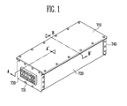
- FIG. 1 is a perspective view showing a battery pack according to a first embodiment of the present invention
- FIG. 2 is an exploded perspective view showing a battery pack according to the first embodiment of the present invention.
- a battery pack includes at least one battery module 100, 200, 300, 400 in which a plurality of battery cells are arranged in one direction; and a housing 710, 720, 730, 740 surrounding the battery module 100, 200, 300, 400, forming an air inlet port 731 at one side surface thereof and forming an air outlet port 741 at other side surface thereof facing the one side surface being arranged opposite thereof, hence, being arranged opposite thereof.
- a slope portion 722 gradually inclined downwardly in a direction from an air inlet port 731 side to the air outlet port 741 and particularly from the air inlet port 731 side to the air outlet port 741 is formed at a bottom surface or plate of the housing 710, 720, 730, 740.
- the slope portion 722 may be inclined downwardly from the air inlet port 731 to the center of the direction perpendicular to the direction in the air outlet port 741 side.
- the housing comprising a top housing 710, bottom housing 720, anterior housing 730, and posterior housing 740.
- a cushioning member 510 may be included between the bottom surface or plate of the housing 710, 720, 730, 740 and the battery module 100, 200, 300, 400.
- slope portion 722 and a first hole 724 may formed to direct fluid from the air inlet port 731 side to the air outlet portion 741 side prior to formation of the cushioning member 510.
- the bottom plate of the housing 710, 720, 730, 740 contacting the battery module 100, 200, 300, 400 may include a module supporting portion 723.
- a module fastening hole 725 for fastening the battery module 100, 200, 300, 400 may be formed at the module supporting portion 723.
- an opening and closing means 726 ( Fig 7 ), such as a valve, may be formed at a first hole 724.
- a pressure sensing section 727 ( Fig 7 ) for controlling the operation of the opening and closing means 726 may be located around the first hole 724 according to the pressure to be applied.
- the battery module 100 includes a plurality of battery cells 10 connected together to provide high power.
- a battery module 100 can include each a plurality of battery cells 10 stacked together in one direction.
- Each battery cell 10 includes a battery case provided with an opening portion, and a cap plate for sealing the opening portion.
- An electrical case includes cathode plate and anode plate and a separator located between the plates.
- the cap plate has a cathode terminal 11 connected with the cathode plate and an anode terminal 12 connected with the anode plate, wherein both terminals 11, 12 protrude outwardly.
- the cathode plate and the anode plate react with electrolyte to generate energy and the energy is transferred to the outside through the cathode terminal 11 and the anode terminal 12.
- the cathode terminal 11 and the anode terminal 12 of two adjacent battery cells 10 may be electrically connected through a bus bar made of nickel.
- a vent is provided between the cathode terminal 11 and the anode terminal 12.
- the vent serves as a pathway through which gas is discharged from the battery cell 10. This can prevent the battery cell to be damaged due to an internal pressure thereof.
- the battery cells 10 have a wide front surface arranged side by side to be opposite each other, wherein the center portion of a plurality of battery cells 10 is provided with the vent. This enables the vent to be aligned with an upper surface of the plurality of battery cells 10 arranged in one direction.
- a barrier 150 is located between adjacent battery cells 10.
- the barrier 150 provides a space between the battery cells 10 to provide a pathway through which a cooling medium can pass.
- a top cover 130 is assembled and mounted on the upper side corresponding to the vent portion in which the vent is formed.
- a pair of end plates 110 is located at outermost both sides of the battery 100. That is, the pair of end plates 110 is located to make surface contact with the outermost battery cells 10 to form a press-fit with the plurality of the inner side of the battery cells 10.
- top cover or plate 130 is located at the upper portion of the plurality of battery cell 10, a side plate 160 is located at a side surface thereof and a bottom plate is located at the bottom surface or plate thereof.
- the side portion of the pair of end plates 110 is bent perpendicular to the a side opposite of the battery cell 10 and the fastening hole 112, 212 for fastening to the side plate 160 is formed at the perpendicularly bent area.
- the fastener member is inserted through the fastening hole 112, 212 to fasten each of the pair of end plates 110 and the side plate 160 together.
- end plate 110 is bent perpendicular to the opposite direction of the battery cell 10 so that it points away from the battery cell 10 and the battery module 100 includes a bottom fastener portion 192 horizontally formed with the bottom surface or plate to be mounted to the module 100.
- the bottom fastener portion 192 of the battery module 100 may be fixed to the bottom surface or plate in which the battery is mounted by the fastener member.
- the fastener member may include a bolt or a stud.
- the bottom surface or plate of the housing forms a slope or slope portion 722 gradually inclined downwardly from the side of air inlet port 731 to the side of the air outlet port 741.
- a first hole 724 is formed at the end of the slope portion 722. As such, even if air having high humidity flows into the air inlet 731 and generates water, e.g. condensation water, the water is naturally discharged into the first hole 724 along the slope or slope portion 722.
- water e.g. condensation water
- the cushioning member 510 is formed between the bottom surface or plate of the housing and the battery module 100, 200, 300 and 400.
- the slope portion 722 and the first hole 724 may be formed before the cushioning member 510.
- the housing of the slope portion 722 is inclined to be gradually sloped downward from the air inlet port 731 to the air outlet port 741, and simultaneously may be formed to be gradually sloped downward from either end of the battery modules 100, 200, 300 and 400 to the center. This enables the water to be discharged from the both ends of the battery module 100, 200, 300 and 400 located prior to the cushioning member 510.
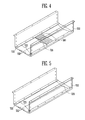
- FIG. 4 is a perspective view showing the lower housing according to a second embodiment of the present invention.
- the cushioning member 510 is formed in at least one area between the bottom surface or plate of the housing and the battery module 100, 200, 300 and 400.
- the slope portion 722 and the first hole 724 may be formed in a direction from the air inlet port 731 to the air discharging or outlet port 741 prior to the cushioning member 510. This enables water generated by air having high humidity to be discharged prior to the cushioning member 510.
- FIG. 5 is a perspective view showing a lower housing according to a third embodiment of the present invention.
- the slope portion 722 formed in the bottom surface or plate of the housing may be formed to extend from the one end of the battery module 100, 200, 300 and 400 in which the air inlet port 731 is formed, to another end of the battery module 100, 200, 300 and 400 in which the air outlet port 741 is formed.
- the first hole 724 for discharging water held in the inner portion of the battery module 100, 200, 300 and 400 is formed at the air outlet port 741.
- air introduced into the battery pack enables the water in the air to be easily discharged externally so that a short circuit within the battery pack is prevented, thereby improving the safety.
- the battery module according to the embodiment is identical to the configuration of the first embodiment except for a shape of the slope portion 722 of the housing, so the detailed description thereof will be omitted.
- FIG. 6 is an exploded perspective view showing the battery pack according to a fourth embodiment of the present invention.
- the battery pack according to the present invention includes at least one battery module 100, 200, 300, and 400 in which the plurality of battery cells is arranged, and a housing surrounding the battery module 100, 200, 300 and 400, having the air inlet port 731 at one side surface thereof and having the air outlet port 741 at other side surface opposite to the one side surface.
- the slope portion 722 is formed at the bottom surface or plate of the housing and is inclined to be gradually sloped downward from the air inlet port 731 to the air discharging or outlet port 741 and the first hole 724 is formed at the end of the slope portion 722.
- the slope portion 722 is inclined to be gradually sloped downward toward any one of the ends in a direction perpendicular to a direction from the air inlet port 731 to the air outlet port 741.
- a module seating portion 750 that is located substantially horizontally with the ground and on which the battery module 100, 200, 300 and 400 is seated may be formed at the upper side of the bottom surface or plate of the housing. At least one second hole 751 is formed at the module seating portion 750. This enables the battery module 100, 200, 300 and 400 to be tilted thereby improving the safety and the water may be easily discharged into the lower portion thereof by the second hole 751 formed at the module seating portion 750.
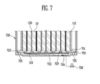
- FIG. 7 is a vertical cross-section view showing the battery pack according to a fourth embodiment.
- an opening and closing means 726 such as a valve, may be formed and further includes a pressure sensing portion 727 for controlling an operation of the opening and closing means 726 based on the pressure applied around the first hole 724.
- a pressure sensing portion 727 for controlling an operation of the opening and closing means 726 based on the pressure applied around the first hole 724.
- the opening and closing means 726 can be opened.
- the opening and closing means may be biased to be closed under ordinary operating conditions, thereby keeping the seal of the battery pack.
Landscapes
- Chemical & Material Sciences (AREA)
- Chemical Kinetics & Catalysis (AREA)
- Electrochemistry (AREA)
- General Chemical & Material Sciences (AREA)
- Engineering & Computer Science (AREA)
- Manufacturing & Machinery (AREA)
- Physics & Mathematics (AREA)
- Electromagnetism (AREA)
- Battery Mounting, Suspending (AREA)
Abstract
Description
- The invention relates to a battery pack.
- Typically, a battery cell is used as an energy source for a mobile unit, an electrical vehicle, hybrid cars and the like and different types of battery cells may be used depending on a type of an external device to which they are applied.
- If a long time-driving and high-power drive such as the electrical vehicle and the hybrid car, which requires high power consumption, it is necessary in order to maximize output and capacity, to have a plurality of battery cells electrically connected to construct a mass battery module.
- The battery module may maximize an output voltage or an output current based on the number of the built-in battery
- In addition, a plurality of battery modules may be electrically connected to assemble a battery pack.
- However, the battery pack of high-capacity has a problem that a large amount of heat is generated in the process of the charge/discharge.
- For this, a cooling system can be used with the high output and high capacity battery pack and the cooling system serves to decrease an internal temperature of the battery pack by providing a cooling medium such as air and the like to one side of the battery pack and discharging the air from the other side of a battery pack.
- In this case, when a humidity of air flowing into the battery pack is high, water may accumulate in the area, thereby blocking the air flow of an internal portion of the battery pack.
- Therefore, if the generated water is not effectively eliminated, the problem rises that a short circuit may be generated within the battery pack.
- The present invention provides a battery pack wherein water generated by air having high humidity flown in the inner portion of the battery pack is easily dumped through a first hole formed at a slope or slope portion of a lower housing and an end of a slope.
- A battery pack according to an embodiment of the present invention includes at least one battery module comprising a plurality of battery cells; and a housing accommodating the at least one battery module and having an inlet port at a first side thereof and an outlet port at a second side thereof opposite the first side, the housing having a bottom surface or plate that has a slope and a first hole at an end of the slope. In particular, the first hole may be arranged at a lower end of the sloped bottom surface or plate.
- In one embodiment, the slope or slope portion is inclined downwardly in a direction from the inlet port towards the outlet port. The slope portion is preferably inclined downwardly from the inlet port and from the outlet port towards an area between the inlet port and the outlet port. The slope portion and/or the slope may be inclined downwardly or sloped towards a longitudinal side of the housing, the longitudinal side extending between first and the second side. In one embodiment, a cushioning member is located between the bottom surface or plate of the housing and the battery module. The slope or slope portion and the first hole are formed in a direction from the inlet port to the outlet portion prior to or after the formation of the cushioning member. In another embodiment, the slope portion and the first hole are formed between the inlet port and the cushioning member or the slope portion and the first hole are formed between the cushioning member and the outlet port. Further, in one embodiment, the slope or slope portion extends from a first end of battery module on which the inlet port is formed to a second end of the battery module on which the outlet port is formed.
- In one embodiment, the battery pack includes a module supporting portion between the bottom surface or plate and the at least one battery module, and optionally a module fastening hole for fastening the at least one battery module may be formed on the module supporting portion.
- In another embodiment, the battery pack includes a module seating portion between the bottom surface or plate of the housing and the at least one battery module, and the module seating portion may optionally have at least one second hole.
- In one embodiment, an opening and closing means, such as a valve, is at the first hole. Additionally, the battery pack may include a pressure sensing section for controlling the operation of the opening and closing means at the first hole.
- Since water generated by humidity within the battery pack is easily discharged according to the present invention, a short circuit in the battery pack caused by e.g. condensation water may be prevented, thereby improving battery safety.
- The accompanying drawings, together with the specification, illustrate exemplary embodiments of the present invention, and, together with the description, serve to explain the principles of the present invention.
-
FIG. 1 . is a perspective view showing a battery pack according to a first embodiment of the present invention. -
FIG. 2 is an exploded perspective view showing a battery pack according to the first embodiment of the present invention. -
FIG. 3A is a cross-sectional view taken along A-A' ofFIG. 1 . -
FIG. 3B is a cross-sectional view taken along B-B' ofFIG. 1 . -
FIG. 4 is a perspective view showing a lower housing according to a second embodiment of the present invention. -
FIG. 5 is a perspective view showing a lower housing according to a third embodiment of the present invention. -
FIG. 6 is an exploded perspective view of a battery pack according to a fourth embodiment of the present invention. -
FIG. 7 is a cross-sectional view showing a portion of a battery pack according to the fourth embodiment of the present invention. - When in the following an element is referred to as being "on" another element, it can be directly on the another element or be indirectly on the another element with one or more intervening elements interposed therebetween. Also, when an element is referred to as being "connected to" another element, it can be directly connected to another element or be indirectly connected to the another element with one or more intervening elements interposed therebetween. Hereinafter, like reference numerals refer to like elements.
-
FIG. 1 is a perspective view showing a battery pack according to a first embodiment of the present invention andFIG. 2 is an exploded perspective view showing a battery pack according to the first embodiment of the present invention. - Referring to
FIGs. 1 and2 , a battery pack according to the present embodiment includes at least onebattery module housing battery module air inlet port 731 at one side surface thereof and forming anair outlet port 741 at other side surface thereof facing the one side surface being arranged opposite thereof, hence, being arranged opposite thereof. Aslope portion 722 gradually inclined downwardly in a direction from anair inlet port 731 side to theair outlet port 741 and particularly from theair inlet port 731 side to theair outlet port 741 is formed at a bottom surface or plate of thehousing slope portion 722 may be inclined downwardly from theair inlet port 731 to the center of the direction perpendicular to the direction in theair outlet port 741 side. - The housing comprising a
top housing 710,bottom housing 720,anterior housing 730, andposterior housing 740. - A
cushioning member 510 may be included between the bottom surface or plate of thehousing battery module - In addition, the
slope portion 722 and afirst hole 724 may formed to direct fluid from theair inlet port 731 side to theair outlet portion 741 side prior to formation of thecushioning member 510. - The bottom plate of the
housing battery module module supporting portion 723. Amodule fastening hole 725 for fastening thebattery module module supporting portion 723. - In addition, an opening and closing means 726(
Fig 7 ), such as a valve, may be formed at afirst hole 724. - A pressure sensing section 727 (
Fig 7 ) for controlling the operation of the opening and closing means 726 may be located around thefirst hole 724 according to the pressure to be applied. - Each configuration of the
battery module 100 of the present invention will be described below. - The
battery module 100 according to the present invention includes a plurality ofbattery cells 10 connected together to provide high power. Such abattery module 100 can include each a plurality ofbattery cells 10 stacked together in one direction. Eachbattery cell 10 includes a battery case provided with an opening portion, and a cap plate for sealing the opening portion. An electrical case includes cathode plate and anode plate and a separator located between the plates. - In addition, the cap plate has a cathode terminal 11 connected with the cathode plate and an
anode terminal 12 connected with the anode plate, wherein bothterminals 11, 12 protrude outwardly. - The cathode plate and the anode plate react with electrolyte to generate energy and the energy is transferred to the outside through the cathode terminal 11 and the
anode terminal 12. The cathode terminal 11 and theanode terminal 12 of twoadjacent battery cells 10 may be electrically connected through a bus bar made of nickel. - In addition, a vent is provided between the cathode terminal 11 and the
anode terminal 12. When a gas pressure generated within thebattery cell 10 is greater than a predetermined pressure, the vent serves as a pathway through which gas is discharged from thebattery cell 10. This can prevent the battery cell to be damaged due to an internal pressure thereof. - The
battery cells 10 have a wide front surface arranged side by side to be opposite each other, wherein the center portion of a plurality ofbattery cells 10 is provided with the vent. This enables the vent to be aligned with an upper surface of the plurality ofbattery cells 10 arranged in one direction. - In addition, a
barrier 150 is located betweenadjacent battery cells 10. Thebarrier 150 provides a space between thebattery cells 10 to provide a pathway through which a cooling medium can pass. - A
top cover 130 is assembled and mounted on the upper side corresponding to the vent portion in which the vent is formed. - In addition, a pair of
end plates 110 is located at outermost both sides of thebattery 100. That is, the pair ofend plates 110 is located to make surface contact with theoutermost battery cells 10 to form a press-fit with the plurality of the inner side of thebattery cells 10. - In addition, the top cover or
plate 130 is located at the upper portion of the plurality ofbattery cell 10, aside plate 160 is located at a side surface thereof and a bottom plate is located at the bottom surface or plate thereof. - In addition, the side portion of the pair of
end plates 110 is bent perpendicular to the a side opposite of thebattery cell 10 and thefastening hole side plate 160 is formed at the perpendicularly bent area. - The fastener member is inserted through the
fastening hole end plates 110 and theside plate 160 together. - The lower portion of
end plate 110 is bent perpendicular to the opposite direction of thebattery cell 10 so that it points away from thebattery cell 10 and thebattery module 100 includes abottom fastener portion 192 horizontally formed with the bottom surface or plate to be mounted to themodule 100. - In this way, the
bottom fastener portion 192 of thebattery module 100 may be fixed to the bottom surface or plate in which the battery is mounted by the fastener member. Herein, the fastener member may include a bolt or a stud. - Referring also to
FIGs. 3A and 3B , the bottom surface or plate of the housing forms a slope orslope portion 722 gradually inclined downwardly from the side ofair inlet port 731 to the side of theair outlet port 741. - In addition, a
first hole 724 is formed at the end of theslope portion 722. As such, even if air having high humidity flows into theair inlet 731 and generates water, e.g. condensation water, the water is naturally discharged into thefirst hole 724 along the slope orslope portion 722. - In one embodiment, the cushioning
member 510 is formed between the bottom surface or plate of the housing and thebattery module slope portion 722 and thefirst hole 724 may be formed before the cushioningmember 510. - Referring to
FIG. 3B , the housing of theslope portion 722 is inclined to be gradually sloped downward from theair inlet port 731 to theair outlet port 741, and simultaneously may be formed to be gradually sloped downward from either end of thebattery modules battery module member 510. -
FIG. 4 is a perspective view showing the lower housing according to a second embodiment of the present invention. - Referring to
FIG. 4 , the cushioningmember 510 is formed in at least one area between the bottom surface or plate of the housing and thebattery module slope portion 722 and thefirst hole 724 may be formed in a direction from theair inlet port 731 to the air discharging oroutlet port 741 prior to the cushioningmember 510. This enables water generated by air having high humidity to be discharged prior to the cushioningmember 510. -
FIG. 5 is a perspective view showing a lower housing according to a third embodiment of the present invention. - Referring to
FIG. 5 , theslope portion 722 formed in the bottom surface or plate of the housing may be formed to extend from the one end of thebattery module air inlet port 731 is formed, to another end of thebattery module air outlet port 741 is formed. - In one embodiment, the
first hole 724 for discharging water held in the inner portion of thebattery module air outlet port 741. - In this way, air introduced into the battery pack enables the water in the air to be easily discharged externally so that a short circuit within the battery pack is prevented, thereby improving the safety.
- The battery module according to the embodiment is identical to the configuration of the first embodiment except for a shape of the
slope portion 722 of the housing, so the detailed description thereof will be omitted. -
FIG. 6 is an exploded perspective view showing the battery pack according to a fourth embodiment of the present invention. - Referring to
FIG. 6 , the battery pack according to the present invention includes at least onebattery module battery module air inlet port 731 at one side surface thereof and having theair outlet port 741 at other side surface opposite to the one side surface. - The
slope portion 722 is formed at the bottom surface or plate of the housing and is inclined to be gradually sloped downward from theair inlet port 731 to the air discharging oroutlet port 741 and thefirst hole 724 is formed at the end of theslope portion 722. - The
slope portion 722 is inclined to be gradually sloped downward toward any one of the ends in a direction perpendicular to a direction from theair inlet port 731 to theair outlet port 741. - A
module seating portion 750 that is located substantially horizontally with the ground and on which thebattery module second hole 751 is formed at themodule seating portion 750. This enables thebattery module second hole 751 formed at themodule seating portion 750. -
FIG. 7 is a vertical cross-section view showing the battery pack according to a fourth embodiment. - Referring to
FIG. 7 , an opening and closing means 726, such as a valve, may be formed and further includes apressure sensing portion 727 for controlling an operation of the opening and closing means 726 based on the pressure applied around thefirst hole 724. When thepressure sensing portion 727 is filled with the water greater than a predetermined pressure, the opening and closing means 726 can be opened. The opening and closing means may be biased to be closed under ordinary operating conditions, thereby keeping the seal of the battery pack.
Claims (15)
- A battery pack comprising:at least one battery module (100) comprising a plurality of battery cells (10); anda housing accommodating the at least one battery module (100) and having an inlet port (731) at a first side thereof and an outlet port (741) at a second side thereof opposite the first side, the housing having a bottom plate, characterized in that the bottom plate comprise a slope portion (722) and a first hole (724) at an end of the slope portion (722).
- The battery pack of claim 1, wherein the slope portion (722) is inclined downwardly in a direction from the inlet port (731) towards the outlet port (741).
- The battery pack of claim 1 or 2, wherein the slope portion (722) is inclined downwardly from the inlet port (731) and from the outlet port (741) towards an area between the inlet port (731) and the outlet port (741).
- The battery pack of any of claims 1 to 3, wherein the slope portion (722) is downwardly sloped towards a longitudinal side plate of the housing.
- The battery pack of any on claims 1 to 4, wherein a cushioning member (510) is located between the bottom plate of the housing and the battery module (100).
- The battery pack of claim 5, wherein the slope portion (722) and the first hole (724) are formed between the inlet port (731) and the cushioning member (510).
- The battery pack of claim 5 or 6, wherein the slope portion (722) and the first hole (724) are formed between the cushioning member (510) and the outlet port (741).
- The battery pack of any of claims 1 to 7, wherein the slope portion (722) extends from a first end of battery module (110) on which the inlet port (731) is formed to a second end of the battery module (110) on which the outlet port (741) is formed.
- The battery pack of any of claims 1 to 8, further comprising a module supporting portion between the bottom plate and the at least one battery module (110).
- The battery pack of claim 9, wherein a module fastening hole for fastening the at least one battery module (110) is formed on the module supporting portion.
- The battery pack of any of claims 1 to 10, further comprising a module seating portion (750) between the bottom plate of the housing and the at least one battery module (110).
- The battery pack of claim 11, wherein the module seating portion (750) has at least one second hole (751).
- The battery pack of any of claims 1 to 12, wherein an opening and closing means (726) is at the first hole (724).
- The battery pack of claim 13, wherein a pressure sensing portion (727) for controlling the operation of the opening and closing means (726) is at the first hole (724).
- The battery pack of claim 13 or 14, wherein the opening and closing means (726) comprises a valve.
Applications Claiming Priority (1)
| Application Number | Priority Date | Filing Date | Title |
|---|---|---|---|
| KR1020110122178A KR101658027B1 (en) | 2011-11-22 | 2011-11-22 | Battery pack |
Publications (2)
| Publication Number | Publication Date |
|---|---|
| EP2597700A1 true EP2597700A1 (en) | 2013-05-29 |
| EP2597700B1 EP2597700B1 (en) | 2015-09-02 |
Family
ID=47018864
Family Applications (1)
| Application Number | Title | Priority Date | Filing Date |
|---|---|---|---|
| EP12187560.3A Active EP2597700B1 (en) | 2011-11-22 | 2012-10-08 | Battery pack |
Country Status (3)
| Country | Link |
|---|---|
| US (1) | US8883336B2 (en) |
| EP (1) | EP2597700B1 (en) |
| KR (1) | KR101658027B1 (en) |
Cited By (7)
| Publication number | Priority date | Publication date | Assignee | Title |
|---|---|---|---|---|
| CN103824984A (en) * | 2014-03-10 | 2014-05-28 | 江西博能上饶客车有限公司 | Quick-changing lithium battery box assembly used for new energy automobile |
| EP2816633A1 (en) * | 2013-06-14 | 2014-12-24 | GS Yuasa International Ltd. | Energy storage apparatus |
| EP2843724A1 (en) * | 2013-08-29 | 2015-03-04 | Samsung SDI Co., Ltd. | A housing for a battery pack with a drainage structure |
| WO2016053416A1 (en) * | 2014-09-30 | 2016-04-07 | Johnson Controls Technology Company | Battery module water management features |
| JP2018088424A (en) * | 2013-06-14 | 2018-06-07 | 株式会社Gsユアサ | Power storage module |
| EP3761388A1 (en) * | 2019-07-05 | 2021-01-06 | Contemporary Amperex Technology Co., Limited | Battery pack |
| DE102020006698A1 (en) | 2020-11-02 | 2022-05-05 | Daimler Ag | battery module and traction battery |
Families Citing this family (30)
| Publication number | Priority date | Publication date | Assignee | Title |
|---|---|---|---|---|
| JP6103238B2 (en) * | 2013-10-24 | 2017-03-29 | 株式会社豊田自動織機 | Battery pack |
| JP6103237B2 (en) * | 2013-10-24 | 2017-03-29 | 株式会社豊田自動織機 | Battery pack |
| KR101624281B1 (en) * | 2014-02-17 | 2016-05-25 | 주식회사 엘지화학 | Battery module and battery pack including the same |
| KR102273784B1 (en) | 2014-10-30 | 2021-07-06 | 삼성에스디아이 주식회사 | Battery pack |
| US10312485B2 (en) * | 2015-07-23 | 2019-06-04 | Ford Global Technologies, Llc | Battery assembly array plate |
| US10950904B2 (en) | 2016-02-29 | 2021-03-16 | Sanyo Electric Co., Ltd. | Battery system and electrically driven vehicle equipped with battery system |
| KR102065098B1 (en) * | 2016-08-12 | 2020-01-10 | 주식회사 엘지화학 | Secondary battery module improved in frame structure and frame assembly for the same |
| US9912023B1 (en) * | 2016-09-07 | 2018-03-06 | Thunder Power New Energy Vehicle Development Company Limited | Battery system housing with integrated cooling pipe |
| JP6664513B2 (en) * | 2016-10-31 | 2020-03-13 | エルジー・ケム・リミテッド | battery pack |
| CN116190878A (en) | 2017-01-27 | 2023-05-30 | Cps 科技控股有限公司 | Battery case |
| JP6860022B2 (en) * | 2017-02-15 | 2021-04-14 | 株式会社村田製作所 | Battery packs, electronics, vehicles, power tools and power storage systems |
| KR20200014317A (en) | 2017-06-09 | 2020-02-10 | 씨피에스 테크놀로지 홀딩스 엘엘씨 | Lead acid battery |
| US11936032B2 (en) | 2017-06-09 | 2024-03-19 | Cps Technology Holdings Llc | Absorbent glass mat battery |
| US20190150691A1 (en) * | 2017-10-25 | 2019-05-23 | Hongli Song | Battery for autonomous floor-cleaning apparatus |
| KR102669974B1 (en) * | 2018-05-21 | 2024-05-29 | 삼성에스디아이 주식회사 | Battery pack |
| KR102716343B1 (en) | 2018-05-25 | 2024-10-14 | 주식회사 엘지에너지솔루션 | Battery housing and battery module including the same |
| JP6743098B2 (en) * | 2018-08-31 | 2020-08-19 | 本田技研工業株式会社 | Battery pack for electric vehicle |
| CN112956071B (en) * | 2018-11-13 | 2023-11-17 | 瑞维安知识产权控股有限责任公司 | Battery pack drainage system |
| KR102366271B1 (en) | 2019-01-10 | 2022-02-21 | 주식회사 엘지에너지솔루션 | Battery Module Having Module Case |
| KR102564496B1 (en) * | 2019-07-02 | 2023-08-04 | 주식회사 엘지에너지솔루션 | Battery Pack Having Connection Plate and Electronic Device and Vehicle |
| KR102035764B1 (en) * | 2019-07-17 | 2019-10-24 | (주)휴먼텍코리아엔지니어링건축사사무소 | Fire fighting power controller device with apartment house |
| KR102398574B1 (en) * | 2019-10-10 | 2022-05-13 | 주식회사 엘지에너지솔루션 | Battery module and battery pack including the same |
| KR102843671B1 (en) * | 2020-01-30 | 2025-08-07 | 주식회사 엘지에너지솔루션 | Battery Module Having Drain Formed and Battery Pack Comprising the Same |
| KR102650084B1 (en) | 2020-03-04 | 2024-03-20 | 주식회사 엘지에너지솔루션 | Battery rack and energy storage system comprising the battery rack |
| KR102952415B1 (en) * | 2020-04-29 | 2026-04-14 | 주식회사 엘지에너지솔루션 | Battery pack with improved fixing structure and gas exhausting structure, and Electronic device and Vehicle comprising the Same |
| KR102900267B1 (en) * | 2020-10-08 | 2025-12-12 | 주식회사 엘지에너지솔루션 | Battery Module, Battery Rack, and Energy Storage System |
| HUE073228T2 (en) | 2021-07-29 | 2026-01-28 | Contemporary Amperex Technology Hong Kong Ltd | Battery, electricity-consuming apparatus, method for manufacturing battery and system of manufacturing battery |
| KR20230169735A (en) * | 2022-06-09 | 2023-12-18 | 에스케이온 주식회사 | Bolt for battery and battery module |
| KR102828743B1 (en) * | 2022-12-14 | 2025-07-03 | 제이트러스트(주) | A battery system |
| CN116345058A (en) * | 2023-04-28 | 2023-06-27 | 惠州亿纬锂能股份有限公司 | A battery module, battery pack and vehicle |
Citations (4)
| Publication number | Priority date | Publication date | Assignee | Title |
|---|---|---|---|---|
| US20030082438A1 (en) * | 2001-10-29 | 2003-05-01 | Young-Hae Kwon | Cooling system for batteries in electric vehicle |
| EP1897739A1 (en) * | 2006-09-07 | 2008-03-12 | Honda Motor Co., Ltd | Electrical device cooling structure in vehicle |
| US20080085445A1 (en) * | 2006-10-06 | 2008-04-10 | Panasonic Ev Energy Co., Ltd. | Exhaust system and battery pack |
| EP2368740A1 (en) * | 2008-12-24 | 2011-09-28 | Toyota Jidosha Kabushiki Kaisha | Temperature control structure for electricity storage module |
Family Cites Families (8)
| Publication number | Priority date | Publication date | Assignee | Title |
|---|---|---|---|---|
| DE10064648C2 (en) * | 1999-12-28 | 2003-09-18 | Honda Motor Co Ltd | battery unit |
| JP3681051B2 (en) * | 1999-12-28 | 2005-08-10 | 本田技研工業株式会社 | Power storage device |
| JP4274759B2 (en) * | 2002-08-16 | 2009-06-10 | ヤマハ発動機株式会社 | Electric motorcycle |
| EP2071647B1 (en) * | 2004-10-08 | 2018-01-17 | Honda Motor Co., Ltd. | Interlock structure of electric component box |
| KR100853621B1 (en) | 2004-10-26 | 2008-08-25 | 주식회사 엘지화학 | Battery pack cooling system |
| KR101141057B1 (en) | 2007-06-28 | 2012-05-03 | 주식회사 엘지화학 | Middle or Large-sized Battery Pack |
| KR101091211B1 (en) | 2008-02-28 | 2011-12-07 | 주식회사 엘지화학 | Jet Type Battery Pack for Electric Vehicles |
| JP5490406B2 (en) * | 2008-12-27 | 2014-05-14 | 三洋電機株式会社 | Power supply for vehicle |
-
2011
- 2011-11-22 KR KR1020110122178A patent/KR101658027B1/en active Active
-
2012
- 2012-08-08 US US13/570,217 patent/US8883336B2/en active Active
- 2012-10-08 EP EP12187560.3A patent/EP2597700B1/en active Active
Patent Citations (4)
| Publication number | Priority date | Publication date | Assignee | Title |
|---|---|---|---|---|
| US20030082438A1 (en) * | 2001-10-29 | 2003-05-01 | Young-Hae Kwon | Cooling system for batteries in electric vehicle |
| EP1897739A1 (en) * | 2006-09-07 | 2008-03-12 | Honda Motor Co., Ltd | Electrical device cooling structure in vehicle |
| US20080085445A1 (en) * | 2006-10-06 | 2008-04-10 | Panasonic Ev Energy Co., Ltd. | Exhaust system and battery pack |
| EP2368740A1 (en) * | 2008-12-24 | 2011-09-28 | Toyota Jidosha Kabushiki Kaisha | Temperature control structure for electricity storage module |
Cited By (12)
| Publication number | Priority date | Publication date | Assignee | Title |
|---|---|---|---|---|
| EP2816633A1 (en) * | 2013-06-14 | 2014-12-24 | GS Yuasa International Ltd. | Energy storage apparatus |
| JP2018088424A (en) * | 2013-06-14 | 2018-06-07 | 株式会社Gsユアサ | Power storage module |
| AU2014203081B2 (en) * | 2013-06-14 | 2018-06-28 | Gs Yuasa International Ltd. | Energy storage apparatus |
| US10522798B2 (en) | 2013-06-14 | 2019-12-31 | Gs Yuasa International Ltd. | Energy storage apparatus |
| EP2843724A1 (en) * | 2013-08-29 | 2015-03-04 | Samsung SDI Co., Ltd. | A housing for a battery pack with a drainage structure |
| US9590280B2 (en) | 2013-08-29 | 2017-03-07 | Samsung Sdi Co., Ltd. | Battery pack |
| CN103824984A (en) * | 2014-03-10 | 2014-05-28 | 江西博能上饶客车有限公司 | Quick-changing lithium battery box assembly used for new energy automobile |
| CN103824984B (en) * | 2014-03-10 | 2016-05-18 | 江西博能上饶客车有限公司 | For the quick change lithium battery box assembly of new-energy automobile |
| WO2016053416A1 (en) * | 2014-09-30 | 2016-04-07 | Johnson Controls Technology Company | Battery module water management features |
| EP3761388A1 (en) * | 2019-07-05 | 2021-01-06 | Contemporary Amperex Technology Co., Limited | Battery pack |
| US11611116B2 (en) | 2019-07-05 | 2023-03-21 | Contemporary Amperex Technology Co., Limited | Battery pack |
| DE102020006698A1 (en) | 2020-11-02 | 2022-05-05 | Daimler Ag | battery module and traction battery |
Also Published As
| Publication number | Publication date |
|---|---|
| US20130130073A1 (en) | 2013-05-23 |
| EP2597700B1 (en) | 2015-09-02 |
| KR101658027B1 (en) | 2016-09-21 |
| US8883336B2 (en) | 2014-11-11 |
| KR20130056530A (en) | 2013-05-30 |
Similar Documents
| Publication | Publication Date | Title |
|---|---|---|
| EP2597700B1 (en) | Battery pack | |
| CN103378319B (en) | Battery module | |
| KR100612305B1 (en) | Battery module | |
| JP6540628B2 (en) | Battery pack | |
| US20140023893A1 (en) | Secondary battery device | |
| KR101271883B1 (en) | Battery module | |
| CN105322248B (en) | Battery module, battery pack and device including the battery pack | |
| CN101946342B (en) | battery with multiple cells | |
| US8574747B2 (en) | Car power source apparatus | |
| US10312561B2 (en) | Unit cell pack | |
| JP6627682B2 (en) | Battery pack | |
| US12580284B2 (en) | Battery module including removable fuse assembly and battery pack including the same | |
| KR101708367B1 (en) | Battery pack | |
| US11621447B2 (en) | Secondary battery pack including cell frame with coating prevention part | |
| US10658649B2 (en) | Battery pack electronic equipment chamber and battery package comprising same | |
| CN103262295B (en) | Electrical storage device | |
| KR20090038850A (en) | Lead acid battery | |
| CN111357131B (en) | Battery pack including cell limiter | |
| JP2002157982A (en) | Battery module | |
| US11133557B2 (en) | On-vehicle battery pack | |
| US20160072166A1 (en) | Battery Package | |
| KR20140123757A (en) | Battery pack | |
| CN120049119A (en) | Battery pack and vehicle including the same | |
| JP6702116B2 (en) | Battery module | |
| JP2018032591A (en) | Battery pack |
Legal Events
| Date | Code | Title | Description |
|---|---|---|---|
| PUAI | Public reference made under article 153(3) epc to a published international application that has entered the european phase |
Free format text: ORIGINAL CODE: 0009012 |
|
| AK | Designated contracting states |
Kind code of ref document: A1 Designated state(s): AL AT BE BG CH CY CZ DE DK EE ES FI FR GB GR HR HU IE IS IT LI LT LU LV MC MK MT NL NO PL PT RO RS SE SI SK SM TR |
|
| AX | Request for extension of the european patent |
Extension state: BA ME |
|
| 17P | Request for examination filed |
Effective date: 20131129 |
|
| RBV | Designated contracting states (corrected) |
Designated state(s): AL AT BE BG CH CY CZ DE DK EE ES FI FR GB GR HR HU IE IS IT LI LT LU LV MC MK MT NL NO PL PT RO RS SE SI SK SM TR |
|
| GRAP | Despatch of communication of intention to grant a patent |
Free format text: ORIGINAL CODE: EPIDOSNIGR1 |
|
| RIC1 | Information provided on ipc code assigned before grant |
Ipc: H01M 10/663 20140101ALI20150324BHEP Ipc: H01M 10/6563 20140101ALI20150324BHEP Ipc: H01M 2/10 20060101AFI20150324BHEP Ipc: H01M 10/625 20140101ALI20150324BHEP |
|
| INTG | Intention to grant announced |
Effective date: 20150417 |
|
| GRAS | Grant fee paid |
Free format text: ORIGINAL CODE: EPIDOSNIGR3 |
|
| GRAA | (expected) grant |
Free format text: ORIGINAL CODE: 0009210 |
|
| AK | Designated contracting states |
Kind code of ref document: B1 Designated state(s): AL AT BE BG CH CY CZ DE DK EE ES FI FR GB GR HR HU IE IS IT LI LT LU LV MC MK MT NL NO PL PT RO RS SE SI SK SM TR |
|
| REG | Reference to a national code |
Ref country code: GB Ref legal event code: FG4D |
|
| REG | Reference to a national code |
Ref country code: AT Ref legal event code: REF Ref document number: 747111 Country of ref document: AT Kind code of ref document: T Effective date: 20150915 Ref country code: CH Ref legal event code: EP |
|
| REG | Reference to a national code |
Ref country code: IE Ref legal event code: FG4D |
|
| REG | Reference to a national code |
Ref country code: DE Ref legal event code: R096 Ref document number: 602012010190 Country of ref document: DE |
|
| REG | Reference to a national code |
Ref country code: FR Ref legal event code: PLFP Year of fee payment: 4 |
|
| REG | Reference to a national code |
Ref country code: AT Ref legal event code: MK05 Ref document number: 747111 Country of ref document: AT Kind code of ref document: T Effective date: 20150902 |
|
| PG25 | Lapsed in a contracting state [announced via postgrant information from national office to epo] |
Ref country code: FI Free format text: LAPSE BECAUSE OF FAILURE TO SUBMIT A TRANSLATION OF THE DESCRIPTION OR TO PAY THE FEE WITHIN THE PRESCRIBED TIME-LIMIT Effective date: 20150902 Ref country code: GR Free format text: LAPSE BECAUSE OF FAILURE TO SUBMIT A TRANSLATION OF THE DESCRIPTION OR TO PAY THE FEE WITHIN THE PRESCRIBED TIME-LIMIT Effective date: 20151203 Ref country code: LT Free format text: LAPSE BECAUSE OF FAILURE TO SUBMIT A TRANSLATION OF THE DESCRIPTION OR TO PAY THE FEE WITHIN THE PRESCRIBED TIME-LIMIT Effective date: 20150902 Ref country code: LV Free format text: LAPSE BECAUSE OF FAILURE TO SUBMIT A TRANSLATION OF THE DESCRIPTION OR TO PAY THE FEE WITHIN THE PRESCRIBED TIME-LIMIT Effective date: 20150902 Ref country code: NO Free format text: LAPSE BECAUSE OF FAILURE TO SUBMIT A TRANSLATION OF THE DESCRIPTION OR TO PAY THE FEE WITHIN THE PRESCRIBED TIME-LIMIT Effective date: 20151202 |
|
| REG | Reference to a national code |
Ref country code: LT Ref legal event code: MG4D Ref country code: NL Ref legal event code: MP Effective date: 20150902 |
|
| PG25 | Lapsed in a contracting state [announced via postgrant information from national office to epo] |
Ref country code: AT Free format text: LAPSE BECAUSE OF FAILURE TO SUBMIT A TRANSLATION OF THE DESCRIPTION OR TO PAY THE FEE WITHIN THE PRESCRIBED TIME-LIMIT Effective date: 20150902 Ref country code: PL Free format text: LAPSE BECAUSE OF FAILURE TO SUBMIT A TRANSLATION OF THE DESCRIPTION OR TO PAY THE FEE WITHIN THE PRESCRIBED TIME-LIMIT Effective date: 20150902 Ref country code: RS Free format text: LAPSE BECAUSE OF FAILURE TO SUBMIT A TRANSLATION OF THE DESCRIPTION OR TO PAY THE FEE WITHIN THE PRESCRIBED TIME-LIMIT Effective date: 20150902 Ref country code: SE Free format text: LAPSE BECAUSE OF FAILURE TO SUBMIT A TRANSLATION OF THE DESCRIPTION OR TO PAY THE FEE WITHIN THE PRESCRIBED TIME-LIMIT Effective date: 20150902 Ref country code: ES Free format text: LAPSE BECAUSE OF FAILURE TO SUBMIT A TRANSLATION OF THE DESCRIPTION OR TO PAY THE FEE WITHIN THE PRESCRIBED TIME-LIMIT Effective date: 20150902 |
|
| PG25 | Lapsed in a contracting state [announced via postgrant information from national office to epo] |
Ref country code: SK Free format text: LAPSE BECAUSE OF FAILURE TO SUBMIT A TRANSLATION OF THE DESCRIPTION OR TO PAY THE FEE WITHIN THE PRESCRIBED TIME-LIMIT Effective date: 20150902 Ref country code: IS Free format text: LAPSE BECAUSE OF FAILURE TO SUBMIT A TRANSLATION OF THE DESCRIPTION OR TO PAY THE FEE WITHIN THE PRESCRIBED TIME-LIMIT Effective date: 20160102 Ref country code: CZ Free format text: LAPSE BECAUSE OF FAILURE TO SUBMIT A TRANSLATION OF THE DESCRIPTION OR TO PAY THE FEE WITHIN THE PRESCRIBED TIME-LIMIT Effective date: 20150902 Ref country code: EE Free format text: LAPSE BECAUSE OF FAILURE TO SUBMIT A TRANSLATION OF THE DESCRIPTION OR TO PAY THE FEE WITHIN THE PRESCRIBED TIME-LIMIT Effective date: 20150902 Ref country code: IT Free format text: LAPSE BECAUSE OF FAILURE TO SUBMIT A TRANSLATION OF THE DESCRIPTION OR TO PAY THE FEE WITHIN THE PRESCRIBED TIME-LIMIT Effective date: 20150902 Ref country code: NL Free format text: LAPSE BECAUSE OF FAILURE TO SUBMIT A TRANSLATION OF THE DESCRIPTION OR TO PAY THE FEE WITHIN THE PRESCRIBED TIME-LIMIT Effective date: 20150902 |
|
| PG25 | Lapsed in a contracting state [announced via postgrant information from national office to epo] |
Ref country code: PT Free format text: LAPSE BECAUSE OF FAILURE TO SUBMIT A TRANSLATION OF THE DESCRIPTION OR TO PAY THE FEE WITHIN THE PRESCRIBED TIME-LIMIT Effective date: 20160104 Ref country code: RO Free format text: LAPSE BECAUSE OF FAILURE TO SUBMIT A TRANSLATION OF THE DESCRIPTION OR TO PAY THE FEE WITHIN THE PRESCRIBED TIME-LIMIT Effective date: 20150902 |
|
| REG | Reference to a national code |
Ref country code: CH Ref legal event code: PL |
|
| REG | Reference to a national code |
Ref country code: DE Ref legal event code: R097 Ref document number: 602012010190 Country of ref document: DE |
|
| PG25 | Lapsed in a contracting state [announced via postgrant information from national office to epo] |
Ref country code: MC Free format text: LAPSE BECAUSE OF FAILURE TO SUBMIT A TRANSLATION OF THE DESCRIPTION OR TO PAY THE FEE WITHIN THE PRESCRIBED TIME-LIMIT Effective date: 20150902 |
|
| PLBE | No opposition filed within time limit |
Free format text: ORIGINAL CODE: 0009261 |
|
| STAA | Information on the status of an ep patent application or granted ep patent |
Free format text: STATUS: NO OPPOSITION FILED WITHIN TIME LIMIT |
|
| REG | Reference to a national code |
Ref country code: IE Ref legal event code: MM4A |
|
| PG25 | Lapsed in a contracting state [announced via postgrant information from national office to epo] |
Ref country code: CH Free format text: LAPSE BECAUSE OF NON-PAYMENT OF DUE FEES Effective date: 20151031 Ref country code: LI Free format text: LAPSE BECAUSE OF NON-PAYMENT OF DUE FEES Effective date: 20151031 |
|
| 26N | No opposition filed |
Effective date: 20160603 |
|
| PG25 | Lapsed in a contracting state [announced via postgrant information from national office to epo] |
Ref country code: SI Free format text: LAPSE BECAUSE OF FAILURE TO SUBMIT A TRANSLATION OF THE DESCRIPTION OR TO PAY THE FEE WITHIN THE PRESCRIBED TIME-LIMIT Effective date: 20150902 Ref country code: DK Free format text: LAPSE BECAUSE OF FAILURE TO SUBMIT A TRANSLATION OF THE DESCRIPTION OR TO PAY THE FEE WITHIN THE PRESCRIBED TIME-LIMIT Effective date: 20150902 |
|
| REG | Reference to a national code |
Ref country code: FR Ref legal event code: PLFP Year of fee payment: 5 |
|
| PG25 | Lapsed in a contracting state [announced via postgrant information from national office to epo] |
Ref country code: IE Free format text: LAPSE BECAUSE OF NON-PAYMENT OF DUE FEES Effective date: 20151008 |
|
| PG25 | Lapsed in a contracting state [announced via postgrant information from national office to epo] |
Ref country code: BE Free format text: LAPSE BECAUSE OF FAILURE TO SUBMIT A TRANSLATION OF THE DESCRIPTION OR TO PAY THE FEE WITHIN THE PRESCRIBED TIME-LIMIT Effective date: 20150902 |
|
| PG25 | Lapsed in a contracting state [announced via postgrant information from national office to epo] |
Ref country code: BG Free format text: LAPSE BECAUSE OF FAILURE TO SUBMIT A TRANSLATION OF THE DESCRIPTION OR TO PAY THE FEE WITHIN THE PRESCRIBED TIME-LIMIT Effective date: 20150902 Ref country code: HU Free format text: LAPSE BECAUSE OF FAILURE TO SUBMIT A TRANSLATION OF THE DESCRIPTION OR TO PAY THE FEE WITHIN THE PRESCRIBED TIME-LIMIT; INVALID AB INITIO Effective date: 20121008 Ref country code: SM Free format text: LAPSE BECAUSE OF FAILURE TO SUBMIT A TRANSLATION OF THE DESCRIPTION OR TO PAY THE FEE WITHIN THE PRESCRIBED TIME-LIMIT Effective date: 20150902 |
|
| PG25 | Lapsed in a contracting state [announced via postgrant information from national office to epo] |
Ref country code: CY Free format text: LAPSE BECAUSE OF FAILURE TO SUBMIT A TRANSLATION OF THE DESCRIPTION OR TO PAY THE FEE WITHIN THE PRESCRIBED TIME-LIMIT Effective date: 20150902 |
|
| PG25 | Lapsed in a contracting state [announced via postgrant information from national office to epo] |
Ref country code: HR Free format text: LAPSE BECAUSE OF FAILURE TO SUBMIT A TRANSLATION OF THE DESCRIPTION OR TO PAY THE FEE WITHIN THE PRESCRIBED TIME-LIMIT Effective date: 20150902 |
|
| PG25 | Lapsed in a contracting state [announced via postgrant information from national office to epo] |
Ref country code: MT Free format text: LAPSE BECAUSE OF FAILURE TO SUBMIT A TRANSLATION OF THE DESCRIPTION OR TO PAY THE FEE WITHIN THE PRESCRIBED TIME-LIMIT Effective date: 20150902 |
|
| REG | Reference to a national code |
Ref country code: FR Ref legal event code: PLFP Year of fee payment: 6 |
|
| PG25 | Lapsed in a contracting state [announced via postgrant information from national office to epo] |
Ref country code: LU Free format text: LAPSE BECAUSE OF NON-PAYMENT OF DUE FEES Effective date: 20151008 |
|
| PG25 | Lapsed in a contracting state [announced via postgrant information from national office to epo] |
Ref country code: TR Free format text: LAPSE BECAUSE OF FAILURE TO SUBMIT A TRANSLATION OF THE DESCRIPTION OR TO PAY THE FEE WITHIN THE PRESCRIBED TIME-LIMIT Effective date: 20150902 Ref country code: MK Free format text: LAPSE BECAUSE OF FAILURE TO SUBMIT A TRANSLATION OF THE DESCRIPTION OR TO PAY THE FEE WITHIN THE PRESCRIBED TIME-LIMIT Effective date: 20150902 |
|
| REG | Reference to a national code |
Ref country code: FR Ref legal event code: PLFP Year of fee payment: 7 |
|
| PG25 | Lapsed in a contracting state [announced via postgrant information from national office to epo] |
Ref country code: AL Free format text: LAPSE BECAUSE OF FAILURE TO SUBMIT A TRANSLATION OF THE DESCRIPTION OR TO PAY THE FEE WITHIN THE PRESCRIBED TIME-LIMIT Effective date: 20150902 |
|
| REG | Reference to a national code |
Ref country code: DE Ref legal event code: R079 Ref document number: 602012010190 Country of ref document: DE Free format text: PREVIOUS MAIN CLASS: H01M0002100000 Ipc: H01M0050200000 |
|
| P01 | Opt-out of the competence of the unified patent court (upc) registered |
Effective date: 20230530 |
|
| PGFP | Annual fee paid to national office [announced via postgrant information from national office to epo] |
Ref country code: FR Payment date: 20250930 Year of fee payment: 14 |
|
| PGFP | Annual fee paid to national office [announced via postgrant information from national office to epo] |
Ref country code: DE Payment date: 20250930 Year of fee payment: 14 |
|
| PGFP | Annual fee paid to national office [announced via postgrant information from national office to epo] |
Ref country code: GB Payment date: 20251001 Year of fee payment: 14 |