EP2597535A2 - Image carrier and image forming apparatus having the same - Google Patents
Image carrier and image forming apparatus having the same Download PDFInfo
- Publication number
- EP2597535A2 EP2597535A2 EP12194470.6A EP12194470A EP2597535A2 EP 2597535 A2 EP2597535 A2 EP 2597535A2 EP 12194470 A EP12194470 A EP 12194470A EP 2597535 A2 EP2597535 A2 EP 2597535A2
- Authority
- EP
- European Patent Office
- Prior art keywords
- image carrier
- image
- flange
- forming apparatus
- carrier body
- Prior art date
- Legal status (The legal status is an assumption and is not a legal conclusion. Google has not performed a legal analysis and makes no representation as to the accuracy of the status listed.)
- Granted
Links
Images



Classifications
-
- G—PHYSICS
- G03—PHOTOGRAPHY; CINEMATOGRAPHY; ANALOGOUS TECHNIQUES USING WAVES OTHER THAN OPTICAL WAVES; ELECTROGRAPHY; HOLOGRAPHY
- G03G—ELECTROGRAPHY; ELECTROPHOTOGRAPHY; MAGNETOGRAPHY
- G03G15/00—Apparatus for electrographic processes using a charge pattern
- G03G15/06—Apparatus for electrographic processes using a charge pattern for developing
-
- G—PHYSICS
- G03—PHOTOGRAPHY; CINEMATOGRAPHY; ANALOGOUS TECHNIQUES USING WAVES OTHER THAN OPTICAL WAVES; ELECTROGRAPHY; HOLOGRAPHY
- G03G—ELECTROGRAPHY; ELECTROPHOTOGRAPHY; MAGNETOGRAPHY
- G03G15/00—Apparatus for electrographic processes using a charge pattern
- G03G15/75—Details relating to xerographic drum, band or plate, e.g. replacing, testing
- G03G15/751—Details relating to xerographic drum, band or plate, e.g. replacing, testing relating to drum
-
- G—PHYSICS
- G03—PHOTOGRAPHY; CINEMATOGRAPHY; ANALOGOUS TECHNIQUES USING WAVES OTHER THAN OPTICAL WAVES; ELECTROGRAPHY; HOLOGRAPHY
- G03G—ELECTROGRAPHY; ELECTROPHOTOGRAPHY; MAGNETOGRAPHY
- G03G21/00—Arrangements not provided for by groups G03G13/00 - G03G19/00, e.g. cleaning, elimination of residual charge
- G03G21/10—Collecting or recycling waste developer
-
- G—PHYSICS
- G03—PHOTOGRAPHY; CINEMATOGRAPHY; ANALOGOUS TECHNIQUES USING WAVES OTHER THAN OPTICAL WAVES; ELECTROGRAPHY; HOLOGRAPHY
- G03G—ELECTROGRAPHY; ELECTROPHOTOGRAPHY; MAGNETOGRAPHY
- G03G21/00—Arrangements not provided for by groups G03G13/00 - G03G19/00, e.g. cleaning, elimination of residual charge
- G03G21/16—Mechanical means for facilitating the maintenance of the apparatus, e.g. modular arrangements
-
- G—PHYSICS
- G03—PHOTOGRAPHY; CINEMATOGRAPHY; ANALOGOUS TECHNIQUES USING WAVES OTHER THAN OPTICAL WAVES; ELECTROGRAPHY; HOLOGRAPHY
- G03G—ELECTROGRAPHY; ELECTROPHOTOGRAPHY; MAGNETOGRAPHY
- G03G21/00—Arrangements not provided for by groups G03G13/00 - G03G19/00, e.g. cleaning, elimination of residual charge
- G03G21/20—Humidity or temperature control also ozone evacuation; Internal apparatus environment control
- G03G21/206—Conducting air through the machine, e.g. for cooling, filtering, removing gases like ozone
Definitions
- Embodiments disclosed herein relate to an image carrier to carry an electrostatic latent image and a visible image, and an image forming apparatus having the same.
- An image forming apparatus is an apparatus designed to form an image on a printing medium according to a signal, and includes a printer, a copy machine, a facsimile, and a multifunctional device which incorporates the functionalities of the printer, the copy machine, and the facsimile (which may be referred to as a multifunctional peripheral device or MFP).
- An electrophotographic image forming apparatus as a type of the image forming apparatus, is provided with an image carrier, a light scanning unit and a developing unit.
- the light scanning unit scans a beam of light to the image carrier charged with a predetermined electric potential to form an electrostatic latent image on the surface of the image carrier, and the developing unit supplies developer to the image carrier, on which the electrostatic latent image is formed, forming a visible image.
- the colors of toner used for the image forming apparatus include yellow (Y), magenta (M), cyan (C) and black (K).
- Y yellow
- M magenta
- C cyan
- K black
- four developing units are needed.
- the first is a single-pass scheme in which an image carrier is provided in each of the four developing units.
- the second is a multi-pass scheme in which an image carrier is shared among the four developing units.
- an image forming apparatus capable of preventing an image carrier from having an operational error due to waste developer.
- an image forming apparatus includes an image carrier, a first image carrier frame, and a second image carrier.
- the image carrier may have an electrostatic latent image formed thereon.
- the first image carrier frame may have one side of the image carrier rotatably installed thereto.
- the second image carrier frame may have an other side of the image carrier rotatably installed thereto.
- the image carrier may include an image carrier body, a first image carrier flange and a second image carrier flange.
- the image carrier body may be provided in the form of a cylinder having a hollowness.
- the first image carrier flange may be installed at one end of the image carrier body.
- the second image carrier flange may be installed at another end of the image carrier body.
- At least one of the first image carrier flange and the second image carrier flange may include a blower fan allowing air to pass through inside the image carrier body in one direction.
- the first image carrier frame may include a guide rib configured to guide air, which is discharged through the one end of the image carrier body, toward a radially outward direction of the image carrier body.
- the second image carrier frame may include a through-hole that allows air to pass therethrough, and be introduced to the inside of the image carrier body.
- the blower fan may allow the air to be drawn to the inside the image carrying body through the other end of the image carrier body, and then to be discharged through the one end of the image carrier body.
- the image forming apparatus may further include a drive gear configured to transmit a rotating force to the image carrier.
- the first image carrier flange may be provided at an outer circumferential surface thereof with a gear portion that is engaged with the drive gear.
- the first image carrier flange may include a flange portion which is provided in the form of a ring.
- the image forming apparatus may further include a gear member which is provided in the form of a ring corresponding to the flange portion and provided at an outer circumferential surface thereof with the gear portion. The gear member may be coupled to the first image carrier flange.
- the guide rib may extend toward the drive gear to guide the air, which is being discharged through the other end of the image carrier body, toward the drive gear.
- an image carrier may be disposed in an image forming apparatus, the image carrier including a hollow image carrier body, a first blower fan disposed at a first end of the image carrier body and a second blower fan disposed at the second end of the image carrier body.
- the first blower fan may draw air into the image carrier body through the second end of the image carrier body, and discharge air out of the image carrier body through the first end of the image carrier body, and the second blower fan may guide air inside of the image carrier body.
- the image carrier may further include a shaft disposed inside the image carrier body along a central longitudinal axis of the image carrier body, wherein the second blower fan guides air in a direction parallel to the central longitudinal axis of the image carrier body.
- the image carrier may further include a first image carrier frame including a first shaft installation hole to support a first end of the shaft and a plurality of guide ribs to guide air discharged from the first blower fan out of the image carrier body in a radially outward direction, and a second image carrier frame including a second shaft installation hole to support a second end of the shaft and a plurality of through holes arranged circumferentially about the second shaft installation through which air is drawn into the image carrier body.
- a first image carrier frame including a first shaft installation hole to support a first end of the shaft and a plurality of guide ribs to guide air discharged from the first blower fan out of the image carrier body in a radially outward direction
- a second image carrier frame including a second shaft installation hole to support a second end of the shaft and a plurality of through holes arranged circumferentially about the second shaft installation through which air is drawn into the image carrier body.
- the image carrier may also include a flange installed at the first end of the image carrier body and a gear member coupled to the flange.
- a drive gear of the image forming apparatus may engage the gear member to transmit a rotating force to the image carrier body, first blower fan, and second blower fan such that air discharged from the first blower fan prevents waste developer from accumulating on the drive gear.
- the first blower fan and second blower fan may include a plurality of blades and, the plurality of blades of the first blower fan may be shaped differently from the plurality of blades of the second blower fan.
- the first blower fan may be a centrifugal type blower fan
- the second blower fan may be an axial type blower fan.
- the air outside of an image carrier body is moved from one end of an image carrier, at which a drive gear is connected, to the other end of the image carrier, so that the waste developer generated from the image carrier is moved from the one end of the image carrier to the other end of the image carrier together with the air. Accordingly, the drive gear provided at the one end of the image carrier is prevented from being contaminated due to the waste developer, so that operational errors of the image carrier may be reduced.
- an image forming apparatus 1 includes a body 10, a printing medium feeding unit 20, a light scanning unit 30, an image carrier unit 40, a developing unit 50, a transfer unit 60, a fixing unit 70, and a printing medium discharge unit 80.
- the body 10 forms the external appearance of the image forming apparatus 1, and supports various components that are installed inside the body10.
- the body 10 may be provided at one side thereof with an opening 10a, through which the components inside of the body 10 are detachable. That is, the opening 10a may allow a user to access various components disposed within the image forming apparatus 1 to remove and/or replace the components as needed, perform maintenance, or clear paper jams for example.
- a side cover 11 having a lower end thereof rotatably installed to the opening 10a of the body 10 is provided so as to open/close the opening 10a with rotation of the side cover 11.
- the body 10 may be provided at an upper surface thereof with a loading portion 10b on which a printing medium having completed with the image formation is loaded.
- consecutively discharged printing mediums may be stacked in a predetermined order on the loading portion 10b.
- a discharge portion 10c is provided at one side of the loading portion 10b to discharge the printing medium having completed with the image formation onto the loading portion 10b.
- the printing medium feeding unit 20 includes a cassette 21 to store a printing medium S, a pickup roller 22 to pick up the printing medium one by one, and a transportation roller 23 to transport the printing medium S, which is picked up, to the transfer unit 60.
- the printing medium S used by the image forming apparatus 1 may include printing paper sheets such as glossy paper, plain paper, art paper, overhead projector film, and the like.
- the light scanning unit 30 may be disposed at a lower side of the image carrier unit 40. That is, the light scanning unit 30 may be positioned below the image carrier unit 40.
- the light scanning unit 30 forms an electrostatic latent image on the surface of an image carrier 42 by scanning light, which corresponds to image information, to the image carrier 42. For example, light may be transmitted from the light scanning unit 30 to the image carrier 42 in an upward diagonal direction, substantially along a path as shown by the dashed lines in FIG. 1 .
- the image carrier unit 40 may include an image carrier housing 41, the image carrier 42, a first image carrier frame 43, a second image carrier frame 44, a charging roller 45, and a shaft 46.
- the image carrier 42 carries an electrostatic latent image formed by the light scanning unit 30 and a visible image formed by the developing unit 50.
- the first image carrier frame 43 and the second image carrier frame 44 are installed at both sides of the image carrier housing 41, respectively, to rotatably support both ends of the image carrier 42.
- the charging roller 45 charges the image carrier 42 with a predetermined electric potential before a beam of light is scanned by the light scanning unit 30.
- the shaft 46 enables the image carrier 42 to be rotatably installed at the first image carrier frame 43.
- a drive gear 12 to drive the image carrier 42 may be provided at an inner side of the body 10.
- the drive gear 12 may rotate the image carrier 42 by engaging a gear member 47 disposed on an end portion of the image carrier 42, adjacent to the drive gear 12.
- the developing unit 50 forms a visible image by supplying developer to the image carrier 42 on which an electrostatic latent image is formed.
- the developing unit 50 is composed of four developing devices 50Y, 50M, 50C, and 50K to receive different colors of developers, for example, Yellow (Y), Magenta (M), Cyan (C), and Black (K), respectively.
- Each of the developing devices 50Y, 50M, 50C, and 50K may include a developer receiving portion 51 to receive developer that is to be supplied to the image carrier 42, a developing roller 53 disposed opposite the image carrier 42 to supply the image carrier 42 with developer, and a feeding roller 52 to supply the developing roller 53 with developer of the developer receiving portion 51.
- the transfer unit 60 may include an intermediate transfer belt 61 supported by support rollers 64 and 65 to transfer a visible image of the image carrier 42 to the printing medium, a first transfer roller 62, and a second transfer roller 63.
- the first transfer roller 62 is disposed opposite to the image carrier 42 while interposing the intermediate transfer belt 61 therebetween to transfer the visible image formed on the image carrier 42 to the intermediate transfer belt 61.
- the second transfer roller 63 is disposed opposite to the support roller 65 while interposing the intermediate transfer belt 61 therebetween to transfer the image on the intermediate transfer belt 61 to the printing medium.
- the fixing unit 70 may include a heating roller 71 having a heating source, and a pressure roller 72 installed opposite the heating roller 71 to press the printing medium to the heating roller 71.
- the heating source may include, for example, a heat lamp (e.g., halogen lamp), heating coil, a resistive heating element, or other heating device. Accordingly, when the printing medium passes through a gap between the heating roller 71 and the pressure roller 72, the developer transferred to the printing medium is fixed to the printing medium by the heat transmitted from the heating roller 71 and by the pressure exerted between the heating roller 71 and the pressure roller 72.
- the printing medium discharge unit 80 includes a discharge roller 81 and a discharge backup roller 82, which are provided at an inner side of the discharge portion 10c, to discharge the printing medium passing through the fixing unit 70 to the outside of the body 10.
- the charging roller 45 uniformly charges the surface of the image carrier 42.
- the light scanning unit 30 scans light, which corresponds to image information of any one color, yellow for example, to the uniformly charged surface of the image carrier 42, that forms an electrostatic latent image corresponding to yellow image information on the image carrier 42.
- a developing bias is applied to the developing roller 53 of the yellow developing unit 50Y to attach a yellow developer to the electrostatic latent image, so that a visible image of yellow color is formed on the image carrier 42.
- the visible image is transferred to the intermediate transfer belt 61 by the first transfer roller 62.
- the light scanning unit 30 scans light, which corresponds to image information of another color, magenta for example, to the light carrier 42, forming an electrostatic latent image corresponding to magenta image information on the image carrier 42.
- the magenta developing device 50M supplies magenta developer to the electrostatic latent image to form a visible image.
- the visible image of magenta color is transferred to the intermediate transfer belt 61 by the first transfer roller 62. In this case, the magenta visible image overlaps the previously transferred yellow visible image.
- a color image is formed on the intermediate transfer belt 61 while having yellow, magenta, cyan, and black images overlapped.
- the resulting color image is transferred to the printing medium which as the printing medium passes through the gap between the intermediate transfer belt 61 and the second transfer roller 63, and the printing medium is discharged to the outside of the body 10 by way of the fixing unit 70 and the printing medium discharge unit 80.
- a waste developer may remain on the image carrier 42. If the waste developer is scattered inside the body 10 and accumulated on the drive gear 12, the rotation of the image carrier 42, which is achieved while being engaged with the drive gear 12, becomes unstable, thereby degrading the image quality.
- the image carrier 42 may include an image carrier body 421 provided in the form of a cylinder having a hollowness, a first image carrier flange 422 installed at one end of the image carrier body 421, and a second image carrier flange 423 installed at the other end (opposite end) of the image carrier body 421.
- the image carrier unit 40 in order to prevent the waste developer from being accumulated on the drive gear 12, is configured such that air is moved from a first end of the image carrier 42, at which the drive gear 12 is positioned, to a second end of the image carrier 42, that is, the opposite end of the first end.
- the first image carrier flange 422 and the second image carrier flange 423 may be integrally provided with blower fans 422b and 423b, respectively, such that air passes through the inside of the image carrier body 421 in one direction.
- Each of the first image carrier flange 422 and the second image carrier flange 423 include flange portions 422a and 423a, respectively, that are provided in the form of a ring.
- Each of the blower fans 422b and 423b is integrally formed with the flange portion 423a at an inner side the flange portion 423a.
- the blower fan 422b and 423b respectively include hubs 422b-1 and 423b-1, on which the shaft 46 is installed, and blades 422b-2 and 423b-2 extending from the hubs 422b-1 and 423b-1 in a radially outward direction of the hubs 422b-1 and 423b-1 and may be connected to the flange portion 423a.
- the blades 422b-2 and 423b-2 include a plurality of blades that are spaced apart from each other in the circumferential direction of the hubs 422b-1 and 423b-1.
- the airfoil shape of the blade and the number of blades may be selected as necessary to achieve the desired effect and performance of the blower fans and/or to achieve a desired airflow.
- the blades may be inclined or curved (e.g., forward-inclined or backward-inclined) or may be substantially straight (e.g., an axial or radial-blade).
- Blower fans 422b and 423b may have similarly shaped blades or may have different blade shapes from one another. Blower fans 422b and 423b may have the same number of blades or may have a different number of blades from one another. Other factors may be considered in selecting the blower fan, including power consumption, noise, heat generation, fan speed (RPM), and the like.
- the blower fans 422b and 423b may be configured to allow air to be drawn to the inside of the image carrier body 421 through the second end of the image carrier body 421 and then to be discharged through the first end (the other, opposite end) of the image carrier body 421.
- the blower fans 422b and 423b may rotate such that air is drawn into the image carrier body 421 through a first end of the image carrier body 421 (e.g., through an end corresponding to the location of blower fan 422b) which corresponds to the same end on which the gear member 47 is disposed, and air may be discharged out through a second end of the image carrier body 421 (e.g., out of an end corresponding to the location of blower fan 423b).
- the blower fans 422b and 423b may rotate such that air is drawn into the image carrier body 421 through a second end of the image carrier body 421 (e.g., through through-hole 44b), and air may be discharged out of the image carrier body 421 through a first end of the image carrier body 421 (e.g., out of the end corresponding to the location of blower fan 422b) which corresponds to the same end on which the gear member 47 is disposed.
- blades 422b-2 may have an inclined shape while blades 423b-2 may be substantially straight.
- blower fan 423b may direct airflow in a direction parallel to the axis of shaft 46 of the image carrier body 421, while blower fan 422b may be a centrifugal fan and direct airflow discharged out of the image carrier body 421 in a different direction, for example in a substantially perpendicular direction (e.g., radially outward direction) relative to the image carrier body 421.
- the first image carrier flange 422 is provided with a gear member 47 coupled thereto that is engaged with the drive gear 12 such that the image carrier 42 receives a driving force through the drive gear 12.
- the gear member 47 may be provided in the form of a ring corresponding to the flange portion 423a of the first image carrier flange 422, and may have a gear portion 47a which is provided with teeth formed at an outer circumferential surface thereof.
- the first image carrier frame 43 and the second image carrier frame 44 may include shaft installation holes 43a and 44a, respectively, at which both ends of the shaft 46 are rotatably installed, respectively.
- the first image carrier frame 43 may include a guide rib 43b to guide air which passes through the inside the image carrier body 421 and then is discharged through the one end of the image carrier body 421.
- the guide rib 43b may include a pair of guide ribs 43b, which extend from a portion adjacent to the shaft installation hole 43a in the radially outward direction of the image carrier body 421, so that the air being discharged through the one end of the image carrier body 421 is guided in a radial outward direction of the image carrier body 421.
- the two guide ribs 43b may extend toward the drive gear 12 so that the air being discharged from the image carrier body 421 is guided to the drive gear 12. As shown in FIG.
- a first guide rib may have a longer length than the second guide rib.
- the first guide rib may extend from the first image carrier frame 43 to the shaft installation hole 43a, while the second guide rib may be disposed above the first guide rib and extend from the first image carrier frame 43 to an area above the shaft installation hole 43a.
- the second image carrier frame 44 may include a through-hole 44b that is provided at a portion adjacent to the shaft installation hole 44a such that air is introduced through the other end of the image carrier body 421 after passing through the second image carrier frame 44. That is, for example, air may flow through the through-hole 44b, through the second image carrier frame 44, out of the end of the image carrier body 421 corresponding to the first image carrier frame 43, toward gear member 47.
- the through-hole 44b for example may include a plurality of through-holes that are provided in a substantially trapezoidal shape and spaced apart from each other in the circumferential direction of the shaft 46 while having the shaft installation hole 44a as a center.
- the through-holes may be spaced apart to correspond to the space formed between the blades of the blower fan.
- the shape of the through-holes may correspond to the shape formed by the intersection of adjacent blades of the blower fan, the hub, and the flange portion.
- the plurality of through-holes may have other shapes, for example, circular, semicircular, square, rectangular, triangular, and the like.
- the image carrier 42 rotates, and the blower fans 422b and 423b, which are integrally formed with the first image carrier flange 422 and the second image carrier flange 423, respectively, rotate.
- the air inside the body 10 passes through the through-hole 44b as shown in FIG. 4 at a second end of the image carrier body 421.
- the air which is introduced to the inside of the image carrier body 421 passes through to a first end of the image carrier body 421, which is opposite of the second end.
- the air being introduced from the second end of the image carrier body 421 is discharged once it passes through the first end of the image carrier body 421.
- the discharged air is guided radially outward of the image carrier body 421 by the two guide ribs 43b, which are provided at the first image carrier frame 43, and then the air is discharged toward the drive gear 12.
- the air is discharged toward the drive gear 12
- air inside the body 10 is drawn through the second end of the image carrier body 421, so the air being discharged toward the drive gear 12 is moved from the first end of the image carrier body 421, at which the drive gear 12 is disposed, to the second end of the image carrier body 421, which again, corresponds to an opposite end of the first end.
- the above-described air flow continues at the outside of the image carrier body 421. Accordingly, even if the waste developer is scattered at the inside of the body 10, the waste developer is moved from the first end of the image carrier body 421 to the second end of the image carrier body 421 together with the air. Accordingly, the waste developer is prevented from being accumulated on the drive gear 12 and the gear member 47 that are positioned at the first end of the image carrier body 421.
- the first image carrier flange 422 and the second image carrier flange 423 may be integrally provided with the blower fans 422b and 423b, respectively, but the present disclosure is not limited thereto.
- only one of the first image carrier flange 422 and the second image carrier flange 423 may be provided with the blower fan.
- the gear member 47 may be provided at the outer circumferential surface thereof with the gear portion 47a which may be coupled to the first image carrier flange 422, but the present disclosure is not limited thereto.
- the gear part 47a may be integrally formed on the outer circumferential surface of the first image carrier flange 422.
- the image forming apparatus may use one or more processors, which may include a microprocessor, central processing unit (CPU), digital signal processor (DSP), or application-specific integrated circuit (ASIC), as well as portions or combinations of these and other processing devices, to perform various functions of the image forming apparatus and image carrier, according to the above-described example embodiments.
- processors which may include a microprocessor, central processing unit (CPU), digital signal processor (DSP), or application-specific integrated circuit (ASIC), as well as portions or combinations of these and other processing devices, to perform various functions of the image forming apparatus and image carrier, according to the above-described example embodiments.
- the image carrier, and the image forming apparatus having the same may be constructed such that operational errors related to waste developer accumulating on a drive gear of the image carrier may be avoided.
- the above-disclosed image carrier is capable of transferring waste developer, which may be scattered inside a body of the image forming apparatus, from one end of the image carrier in which the drive gear is disposed, to an opposite end of the image carrier, by generating an airflow using one or more blower fans.
- the airflow may be directed from a second end of the image carrier having a plurality of through-holes through an image carrier body, and out of a first end of the image carrier which is disposed adjacent to the drive gear.
- the first end of the image carrier may include one or more guide ribs which guides the airflow in an outward radial direction such that waste developer, which would otherwise accumulate on the drive gear, is moved from the first end of the image carrier to the second end of the image carrier.
- the above-disclosed image carrier may be included in various image forming devices, including a printer, a copy machine, a facsimile, and a multifunctional device which incorporates the functionalities of the printer, the copy machine, and the facsimile (which may be referred to as a multifunctional peripheral device or MFP).
- the printer may have the capability for single-sided printing and/or duplex printing, and is not limited to the example embodiment of the printer shown in FIG. 1 . Further, the printer may have more or less than the four developing devices shown in FIG.
- the disclosure may include only a single developing device with a single color, or may include developing devices having colors other than, or in addition to, yellow, magenta, cyan, and/or black, (e.g., orange, green, blue, red, etc.).
Landscapes
- Physics & Mathematics (AREA)
- General Physics & Mathematics (AREA)
- Life Sciences & Earth Sciences (AREA)
- Engineering & Computer Science (AREA)
- Environmental & Geological Engineering (AREA)
- Atmospheric Sciences (AREA)
- Biodiversity & Conservation Biology (AREA)
- Ecology (AREA)
- Environmental Sciences (AREA)
- Sustainable Development (AREA)
- Electrophotography Configuration And Component (AREA)
- Discharging, Photosensitive Material Shape In Electrophotography (AREA)
Abstract
Description
- Embodiments disclosed herein relate to an image carrier to carry an electrostatic latent image and a visible image, and an image forming apparatus having the same.
- An image forming apparatus is an apparatus designed to form an image on a printing medium according to a signal, and includes a printer, a copy machine, a facsimile, and a multifunctional device which incorporates the functionalities of the printer, the copy machine, and the facsimile (which may be referred to as a multifunctional peripheral device or MFP).
- An electrophotographic image forming apparatus, as a type of the image forming apparatus, is provided with an image carrier, a light scanning unit and a developing unit. The light scanning unit scans a beam of light to the image carrier charged with a predetermined electric potential to form an electrostatic latent image on the surface of the image carrier, and the developing unit supplies developer to the image carrier, on which the electrostatic latent image is formed, forming a visible image.
- In general, the colors of toner used for the image forming apparatus include yellow (Y), magenta (M), cyan (C) and black (K). In order to attach the four colors of toner to the electrostatic latent image, four developing units are needed.
- There are two variants of image forming schemes. The first is a single-pass scheme in which an image carrier is provided in each of the four developing units. The second is a multi-pass scheme in which an image carrier is shared among the four developing units.
- Therefore, it is an aspect of the present disclosure to provide an image forming apparatus capable of preventing an image carrier from having an operational error due to waste developer.
- Additional aspects of the disclosure will be set forth in part in the description which follows and, in part, will be apparent from the description, or may be learned by practice of the disclosure.
- According to the present invention there is provided an apparatus and method as set forth in the appended claims. Other features of the invention will be apparent from the dependent claims, and the description which follows.
- In accordance with one aspect of the present disclosure, an image forming apparatus includes an image carrier, a first image carrier frame, and a second image carrier. The image carrier may have an electrostatic latent image formed thereon. The first image carrier frame may have one side of the image carrier rotatably installed thereto. The second image carrier frame may have an other side of the image carrier rotatably installed thereto. The image carrier may include an image carrier body, a first image carrier flange and a second image carrier flange. The image carrier body may be provided in the form of a cylinder having a hollowness. The first image carrier flange may be installed at one end of the image carrier body. The second image carrier flange may be installed at another end of the image carrier body. At least one of the first image carrier flange and the second image carrier flange may include a blower fan allowing air to pass through inside the image carrier body in one direction. The first image carrier frame may include a guide rib configured to guide air, which is discharged through the one end of the image carrier body, toward a radially outward direction of the image carrier body. The second image carrier frame may include a through-hole that allows air to pass therethrough, and be introduced to the inside of the image carrier body.
- The blower fan may allow the air to be drawn to the inside the image carrying body through the other end of the image carrier body, and then to be discharged through the one end of the image carrier body.
- The image forming apparatus may further include a drive gear configured to transmit a rotating force to the image carrier. The first image carrier flange may be provided at an outer circumferential surface thereof with a gear portion that is engaged with the drive gear.
- The first image carrier flange may include a flange portion which is provided in the form of a ring. The image forming apparatus may further include a gear member which is provided in the form of a ring corresponding to the flange portion and provided at an outer circumferential surface thereof with the gear portion. The gear member may be coupled to the first image carrier flange.
- The guide rib may extend toward the drive gear to guide the air, which is being discharged through the other end of the image carrier body, toward the drive gear.
- According to another aspect of the disclosure, an image carrier may be disposed in an image forming apparatus, the image carrier including a hollow image carrier body, a first blower fan disposed at a first end of the image carrier body and a second blower fan disposed at the second end of the image carrier body. The first blower fan may draw air into the image carrier body through the second end of the image carrier body, and discharge air out of the image carrier body through the first end of the image carrier body, and the second blower fan may guide air inside of the image carrier body. The image carrier may further include a shaft disposed inside the image carrier body along a central longitudinal axis of the image carrier body, wherein the second blower fan guides air in a direction parallel to the central longitudinal axis of the image carrier body.
- The image carrier may further include a first image carrier frame including a first shaft installation hole to support a first end of the shaft and a plurality of guide ribs to guide air discharged from the first blower fan out of the image carrier body in a radially outward direction, and a second image carrier frame including a second shaft installation hole to support a second end of the shaft and a plurality of through holes arranged circumferentially about the second shaft installation through which air is drawn into the image carrier body.
- The image carrier may also include a flange installed at the first end of the image carrier body and a gear member coupled to the flange. A drive gear of the image forming apparatus may engage the gear member to transmit a rotating force to the image carrier body, first blower fan, and second blower fan such that air discharged from the first blower fan prevents waste developer from accumulating on the drive gear.
- The first blower fan and second blower fan may include a plurality of blades and, the plurality of blades of the first blower fan may be shaped differently from the plurality of blades of the second blower fan. The first blower fan may be a centrifugal type blower fan, and the second blower fan may be an axial type blower fan.
- As described above, the air outside of an image carrier body is moved from one end of an image carrier, at which a drive gear is connected, to the other end of the image carrier, so that the waste developer generated from the image carrier is moved from the one end of the image carrier to the other end of the image carrier together with the air. Accordingly, the drive gear provided at the one end of the image carrier is prevented from being contaminated due to the waste developer, so that operational errors of the image carrier may be reduced.
- These and/or other aspects of the disclosure will become apparent and more readily appreciated from the following description of the embodiments, taken in conjunction with the accompanying drawings of which:
-
FIG. 1 is a view schematically illustrating an image forming apparatus in accordance with one embodiment of the present disclosure. -
FIG. 2 is a perspective view illustrating an image carrier unit and a developing unit applied to the image forming apparatus in accordance with the embodiment of the present disclosure. -
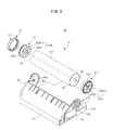
FIG. 3 is an exploded perspective view illustrating an installation state of the image carrier unit applied to the image forming apparatus in accordance with the embodiment of the present disclosure. -
FIG. 4 is a cross-sectional view illustrating the air flow in the image carrier applied to the image forming apparatus in accordance with the embodiment of the present disclosure. - Reference will now be made in detail to the embodiments of the present disclosure, examples of which are illustrated in the accompanying drawings, wherein like reference numerals refer to like elements throughout.
- Referring to
FIG. 1 , animage forming apparatus 1 includes abody 10, a printingmedium feeding unit 20, alight scanning unit 30, animage carrier unit 40, a developingunit 50, atransfer unit 60, afixing unit 70, and a printingmedium discharge unit 80. - The
body 10 forms the external appearance of theimage forming apparatus 1, and supports various components that are installed inside the body10. Thebody 10 may be provided at one side thereof with an opening 10a, through which the components inside of thebody 10 are detachable. That is, the opening 10a may allow a user to access various components disposed within theimage forming apparatus 1 to remove and/or replace the components as needed, perform maintenance, or clear paper jams for example. Aside cover 11 having a lower end thereof rotatably installed to the opening 10a of thebody 10 is provided so as to open/close the opening 10a with rotation of theside cover 11. Thebody 10 may be provided at an upper surface thereof with aloading portion 10b on which a printing medium having completed with the image formation is loaded. For example, when a printing medium is discharged from the printingmedium discharge unit 80, consecutively discharged printing mediums may be stacked in a predetermined order on theloading portion 10b. Adischarge portion 10c is provided at one side of theloading portion 10b to discharge the printing medium having completed with the image formation onto theloading portion 10b. - The printing
medium feeding unit 20 includes acassette 21 to store a printing medium S, apickup roller 22 to pick up the printing medium one by one, and atransportation roller 23 to transport the printing medium S, which is picked up, to thetransfer unit 60. The printing medium S used by theimage forming apparatus 1 may include printing paper sheets such as glossy paper, plain paper, art paper, overhead projector film, and the like. - The
light scanning unit 30 may be disposed at a lower side of theimage carrier unit 40. That is, thelight scanning unit 30 may be positioned below theimage carrier unit 40. Thelight scanning unit 30 forms an electrostatic latent image on the surface of animage carrier 42 by scanning light, which corresponds to image information, to theimage carrier 42. For example, light may be transmitted from thelight scanning unit 30 to theimage carrier 42 in an upward diagonal direction, substantially along a path as shown by the dashed lines inFIG. 1 . - Referring to
FIG. 1 andFIG. 2 , theimage carrier unit 40 may include animage carrier housing 41, theimage carrier 42, a firstimage carrier frame 43, a secondimage carrier frame 44, a chargingroller 45, and ashaft 46. Theimage carrier 42 carries an electrostatic latent image formed by thelight scanning unit 30 and a visible image formed by the developingunit 50. The firstimage carrier frame 43 and the secondimage carrier frame 44 are installed at both sides of theimage carrier housing 41, respectively, to rotatably support both ends of theimage carrier 42. The chargingroller 45 charges theimage carrier 42 with a predetermined electric potential before a beam of light is scanned by thelight scanning unit 30. Theshaft 46 enables theimage carrier 42 to be rotatably installed at the firstimage carrier frame 43. Adrive gear 12 to drive theimage carrier 42 may be provided at an inner side of thebody 10. Thedrive gear 12 may rotate theimage carrier 42 by engaging agear member 47 disposed on an end portion of theimage carrier 42, adjacent to thedrive gear 12. - The developing
unit 50 forms a visible image by supplying developer to theimage carrier 42 on which an electrostatic latent image is formed. The developingunit 50 is composed of four developingdevices - Each of the developing
devices developer receiving portion 51 to receive developer that is to be supplied to theimage carrier 42, a developingroller 53 disposed opposite theimage carrier 42 to supply theimage carrier 42 with developer, and a feedingroller 52 to supply the developingroller 53 with developer of thedeveloper receiving portion 51. - The
transfer unit 60 may include anintermediate transfer belt 61 supported bysupport rollers image carrier 42 to the printing medium, afirst transfer roller 62, and asecond transfer roller 63. Thefirst transfer roller 62 is disposed opposite to theimage carrier 42 while interposing theintermediate transfer belt 61 therebetween to transfer the visible image formed on theimage carrier 42 to theintermediate transfer belt 61. Thesecond transfer roller 63 is disposed opposite to thesupport roller 65 while interposing theintermediate transfer belt 61 therebetween to transfer the image on theintermediate transfer belt 61 to the printing medium. - The fixing
unit 70 may include aheating roller 71 having a heating source, and apressure roller 72 installed opposite theheating roller 71 to press the printing medium to theheating roller 71. The heating source may include, for example, a heat lamp (e.g., halogen lamp), heating coil, a resistive heating element, or other heating device. Accordingly, when the printing medium passes through a gap between theheating roller 71 and thepressure roller 72, the developer transferred to the printing medium is fixed to the printing medium by the heat transmitted from theheating roller 71 and by the pressure exerted between theheating roller 71 and thepressure roller 72. - Meanwhile, the printing
medium discharge unit 80 includes adischarge roller 81 and adischarge backup roller 82, which are provided at an inner side of thedischarge portion 10c, to discharge the printing medium passing through the fixingunit 70 to the outside of thebody 10. - Hereinafter, the operation of the image forming apparatus will be described. If a printing operation begins, the charging
roller 45 uniformly charges the surface of theimage carrier 42. Thelight scanning unit 30 scans light, which corresponds to image information of any one color, yellow for example, to the uniformly charged surface of theimage carrier 42, that forms an electrostatic latent image corresponding to yellow image information on theimage carrier 42. - Subsequently, a developing bias is applied to the developing
roller 53 of the yellow developingunit 50Y to attach a yellow developer to the electrostatic latent image, so that a visible image of yellow color is formed on theimage carrier 42. The visible image is transferred to theintermediate transfer belt 61 by thefirst transfer roller 62. - After the transfer of the yellow color for a page is completed, the
light scanning unit 30 scans light, which corresponds to image information of another color, magenta for example, to thelight carrier 42, forming an electrostatic latent image corresponding to magenta image information on theimage carrier 42. Themagenta developing device 50M supplies magenta developer to the electrostatic latent image to form a visible image. The visible image of magenta color is transferred to theintermediate transfer belt 61 by thefirst transfer roller 62. In this case, the magenta visible image overlaps the previously transferred yellow visible image. - By performing the above described operation for cyan and black colors, a color image is formed on the
intermediate transfer belt 61 while having yellow, magenta, cyan, and black images overlapped. The resulting color image is transferred to the printing medium which as the printing medium passes through the gap between theintermediate transfer belt 61 and thesecond transfer roller 63, and the printing medium is discharged to the outside of thebody 10 by way of the fixingunit 70 and the printingmedium discharge unit 80. - In the above described process of forming an image on the printing medium, a waste developer may remain on the
image carrier 42. If the waste developer is scattered inside thebody 10 and accumulated on thedrive gear 12, the rotation of theimage carrier 42, which is achieved while being engaged with thedrive gear 12, becomes unstable, thereby degrading the image quality. - Referring to
FIGS. 2 and3 , theimage carrier 42 may include animage carrier body 421 provided in the form of a cylinder having a hollowness, a firstimage carrier flange 422 installed at one end of theimage carrier body 421, and a secondimage carrier flange 423 installed at the other end (opposite end) of theimage carrier body 421. - The
image carrier unit 40, in order to prevent the waste developer from being accumulated on thedrive gear 12, is configured such that air is moved from a first end of theimage carrier 42, at which thedrive gear 12 is positioned, to a second end of theimage carrier 42, that is, the opposite end of the first end. - The first
image carrier flange 422 and the secondimage carrier flange 423 may be integrally provided withblower fans image carrier body 421 in one direction. Each of the firstimage carrier flange 422 and the secondimage carrier flange 423 includeflange portions blower fans flange portion 423a at an inner side theflange portion 423a. Theblower fan hubs 422b-1 and 423b-1, on which theshaft 46 is installed, andblades 422b-2 and 423b-2 extending from thehubs 422b-1 and 423b-1 in a radially outward direction of thehubs 422b-1 and 423b-1 and may be connected to theflange portion 423a. Theblades 422b-2 and 423b-2 include a plurality of blades that are spaced apart from each other in the circumferential direction of thehubs 422b-1 and 423b-1. The airfoil shape of the blade and the number of blades may be selected as necessary to achieve the desired effect and performance of the blower fans and/or to achieve a desired airflow. For example, the blades may be inclined or curved (e.g., forward-inclined or backward-inclined) or may be substantially straight (e.g., an axial or radial-blade).Blower fans Blower fans blower fans image carrier body 421 through the second end of theimage carrier body 421 and then to be discharged through the first end (the other, opposite end) of theimage carrier body 421. For example, theblower fans image carrier body 421 through a first end of the image carrier body 421 (e.g., through an end corresponding to the location ofblower fan 422b) which corresponds to the same end on which thegear member 47 is disposed, and air may be discharged out through a second end of the image carrier body 421 (e.g., out of an end corresponding to the location ofblower fan 423b). Alternatively, and more desirably, theblower fans image carrier body 421 through a second end of the image carrier body 421 (e.g., through through-hole 44b), and air may be discharged out of theimage carrier body 421 through a first end of the image carrier body 421 (e.g., out of the end corresponding to the location ofblower fan 422b) which corresponds to the same end on which thegear member 47 is disposed. As shown inFIG. 3 , for example,blades 422b-2 may have an inclined shape whileblades 423b-2 may be substantially straight. In another alternative embodiment,blower fan 423b may direct airflow in a direction parallel to the axis ofshaft 46 of theimage carrier body 421, whileblower fan 422b may be a centrifugal fan and direct airflow discharged out of theimage carrier body 421 in a different direction, for example in a substantially perpendicular direction (e.g., radially outward direction) relative to theimage carrier body 421. - The first
image carrier flange 422 is provided with agear member 47 coupled thereto that is engaged with thedrive gear 12 such that theimage carrier 42 receives a driving force through thedrive gear 12. Thegear member 47 may be provided in the form of a ring corresponding to theflange portion 423a of the firstimage carrier flange 422, and may have agear portion 47a which is provided with teeth formed at an outer circumferential surface thereof. - The first
image carrier frame 43 and the secondimage carrier frame 44 may includeshaft installation holes shaft 46 are rotatably installed, respectively. - The first
image carrier frame 43 may include aguide rib 43b to guide air which passes through the inside theimage carrier body 421 and then is discharged through the one end of theimage carrier body 421. Theguide rib 43b may include a pair ofguide ribs 43b, which extend from a portion adjacent to theshaft installation hole 43a in the radially outward direction of theimage carrier body 421, so that the air being discharged through the one end of theimage carrier body 421 is guided in a radial outward direction of theimage carrier body 421. For example, the twoguide ribs 43b may extend toward thedrive gear 12 so that the air being discharged from theimage carrier body 421 is guided to thedrive gear 12. As shown inFIG. 3 , for example, a first guide rib may have a longer length than the second guide rib. The first guide rib may extend from the firstimage carrier frame 43 to theshaft installation hole 43a, while the second guide rib may be disposed above the first guide rib and extend from the firstimage carrier frame 43 to an area above theshaft installation hole 43a. - The second
image carrier frame 44 may include a through-hole 44b that is provided at a portion adjacent to theshaft installation hole 44a such that air is introduced through the other end of theimage carrier body 421 after passing through the secondimage carrier frame 44. That is, for example, air may flow through the through-hole 44b, through the secondimage carrier frame 44, out of the end of theimage carrier body 421 corresponding to the firstimage carrier frame 43, towardgear member 47. The through-hole 44b, for example may include a plurality of through-holes that are provided in a substantially trapezoidal shape and spaced apart from each other in the circumferential direction of theshaft 46 while having theshaft installation hole 44a as a center. The through-holes may be spaced apart to correspond to the space formed between the blades of the blower fan. The shape of the through-holes may correspond to the shape formed by the intersection of adjacent blades of the blower fan, the hub, and the flange portion. Alternatively, the plurality of through-holes may have other shapes, for example, circular, semicircular, square, rectangular, triangular, and the like. - Hereinafter, the operation of the image carrier unit will be described with reference to
FIG. 4 in detail. - First, if a rotating force is transmitted to the
gear member 47 through thedrive gear 12, theimage carrier 42 rotates, and theblower fans image carrier flange 422 and the secondimage carrier flange 423, respectively, rotate. According to the rotation of theblower fans body 10 passes through the through-hole 44b as shown inFIG. 4 at a second end of theimage carrier body 421. The air which is introduced to the inside of theimage carrier body 421 passes through to a first end of theimage carrier body 421, which is opposite of the second end. The air being introduced from the second end of theimage carrier body 421 is discharged once it passes through the first end of theimage carrier body 421. The discharged air is guided radially outward of theimage carrier body 421 by the twoguide ribs 43b, which are provided at the firstimage carrier frame 43, and then the air is discharged toward thedrive gear 12. When the air is discharged toward thedrive gear 12, air inside thebody 10 is drawn through the second end of theimage carrier body 421, so the air being discharged toward thedrive gear 12 is moved from the first end of theimage carrier body 421, at which thedrive gear 12 is disposed, to the second end of theimage carrier body 421, which again, corresponds to an opposite end of the first end. - During the rotation of the
image carrier 42, the above-described air flow continues at the outside of theimage carrier body 421. Accordingly, even if the waste developer is scattered at the inside of thebody 10, the waste developer is moved from the first end of theimage carrier body 421 to the second end of theimage carrier body 421 together with the air. Accordingly, the waste developer is prevented from being accumulated on thedrive gear 12 and thegear member 47 that are positioned at the first end of theimage carrier body 421. - The first
image carrier flange 422 and the secondimage carrier flange 423 may be integrally provided with theblower fans image carrier flange 422 and the secondimage carrier flange 423 may be provided with the blower fan. - The
gear member 47 may be provided at the outer circumferential surface thereof with thegear portion 47a which may be coupled to the firstimage carrier flange 422, but the present disclosure is not limited thereto. Thegear part 47a may be integrally formed on the outer circumferential surface of the firstimage carrier flange 422. - The image forming apparatus may use one or more processors, which may include a microprocessor, central processing unit (CPU), digital signal processor (DSP), or application-specific integrated circuit (ASIC), as well as portions or combinations of these and other processing devices, to perform various functions of the image forming apparatus and image carrier, according to the above-described example embodiments.
- In accordance with the above-described example embodiments, the image carrier, and the image forming apparatus having the same, may be constructed such that operational errors related to waste developer accumulating on a drive gear of the image carrier may be avoided. The above-disclosed image carrier is capable of transferring waste developer, which may be scattered inside a body of the image forming apparatus, from one end of the image carrier in which the drive gear is disposed, to an opposite end of the image carrier, by generating an airflow using one or more blower fans. The airflow may be directed from a second end of the image carrier having a plurality of through-holes through an image carrier body, and out of a first end of the image carrier which is disposed adjacent to the drive gear. The first end of the image carrier may include one or more guide ribs which guides the airflow in an outward radial direction such that waste developer, which would otherwise accumulate on the drive gear, is moved from the first end of the image carrier to the second end of the image carrier.
- One of ordinary skill in the art would understand that the above-disclosed image carrier may be included in various image forming devices, including a printer, a copy machine, a facsimile, and a multifunctional device which incorporates the functionalities of the printer, the copy machine, and the facsimile (which may be referred to as a multifunctional peripheral device or MFP). Additionally, the printer may have the capability for single-sided printing and/or duplex printing, and is not limited to the example embodiment of the printer shown in
FIG. 1 . Further, the printer may have more or less than the four developing devices shown inFIG. 1 , and may include only a single developing device with a single color, or may include developing devices having colors other than, or in addition to, yellow, magenta, cyan, and/or black, (e.g., orange, green, blue, red, etc.). - Although a few example embodiments of the present disclosure have been shown and described, it would be appreciated by those skilled in the art that changes may be made to these embodiments without departing from the principles of the disclosure, the scope of which is defined in the claims and their equivalents.
- Attention is directed to all papers and documents which are filed concurrently with or previous to this specification in connection with this application and which are open to public inspection with this specification, and the contents of all such papers and documents are incorporated herein by reference.
- All of the features disclosed in this specification (including any accompanying claims, abstract and drawings), and/or all of the steps of any method or process so disclosed, may be combined in any combination, except combinations where at least some of such features and/or steps are mutually exclusive.
- Each feature disclosed in this specification (including any accompanying claims, abstract and drawings) may be replaced by alternative features serving the same, equivalent or similar purpose, unless expressly stated otherwise. Thus, unless expressly stated otherwise, each feature disclosed is one example only of a generic series of equivalent or similar features.
- The invention is not restricted to the details of the foregoing embodiment(s). The invention extends to any novel one, or any novel combination, of the features disclosed in this specification (including any accompanying claims, abstract and drawings), or to any novel one, or any novel combination, of the steps of any method or process so disclosed.
Claims (9)
- An image forming apparatus, comprising:an image carrier on which an electrostatic latent image is formed; anda shaft to enable the image carrier to be rotatably installed,wherein the image carrier comprises:a hollow image carrier body;a first image carrier flange installed at a first end of the image carrier body; anda second image carrier flange installed at a second end of the image carrier body, opposite of the first end, andwherein at least one of the first image carrier flange and the second image carrier flange is integrally provided with a blower fan to enable air to pass through the image carrier body from the second end of the image carrier body to the first end of the image carrier body.
- The image forming apparatus of claim 1, wherein the first image carrier flange and the second image carrier flange each include a ring-shaped flange portion to correspond to the image carrier body, and
the at least one blower fan is integrally formed with the corresponding flange portion at an inner side of the flange portion. - The image forming apparatus of claim 2, wherein the at least one blower fan comprises a hub at which the shaft is installed, and a plurality of blades which extend from the hub in a radially outward direction of the hub so as to be connected to the flange portion while being spaced apart from each other in a circumferential direction of the hub.
- The image forming apparatus of claim 1, further comprising:a first image carrier frame to rotatably support a first end of the shaft and a second image carrier frame to rotatably support a second end of the shaft, opposite to the first end of the shaft,wherein the first image carrier frame and the second image carrier frame each include a shaft installation hole such that both ends of the shaft are rotatably installed on the shaft installation hole of the first image carrier frame and the shaft installation hole of the second image carrier, respectively,wherein the at least one blower fan enables air to pass through the image carrier body from the second image carrier frame to the first image carrier frame, andwherein the first image carrier frame comprises a guide rib configured to guide air to a radially outward direction of the image carrier body.
- The image forming apparatus of claim 4, further comprising a drive gear configured to transmit a rotating force to the image carrier,
wherein the guide rib extends toward the drive gear such that air being discharged through the first end of the image carrier body is guided toward the drive gear. - The image forming apparatus of claim 4, wherein the second image carrier frame comprises at least one through-hole disposed adjacent to the shaft installation hole such that air is drawn to inside of the image carrier body as the air through the second image carrier frame.
- The image forming apparatus of claim 6, wherein the at least one through-hole comprises a plurality of through-holes that are disposed on the shaft installation hole, which are spaced apart from each other in a circumferential direction of the shaft.
- The image forming apparatus of claim 2, wherein the flange portion corresponding to the first image carrier flange is provided at an outer circumferential surface thereof with a gear portion that is supplied with a rotating force from the drive gear.
- The image forming apparatus of claim 8, further comprising a ring-shaped gear member corresponding to the flange portion of the first image carrier flange, and provided at an outer circumferential surface thereof with the gear portion,
wherein the gear member is coupled to the first image carrier flange.
Applications Claiming Priority (1)
| Application Number | Priority Date | Filing Date | Title |
|---|---|---|---|
| KR1020110125223A KR101887653B1 (en) | 2011-11-28 | 2011-11-28 | Image carrier and image forming apparatus having the same |
Publications (3)
| Publication Number | Publication Date |
|---|---|
| EP2597535A2 true EP2597535A2 (en) | 2013-05-29 |
| EP2597535A3 EP2597535A3 (en) | 2015-02-18 |
| EP2597535B1 EP2597535B1 (en) | 2019-03-27 |
Family
ID=47500911
Family Applications (1)
| Application Number | Title | Priority Date | Filing Date |
|---|---|---|---|
| EP12194470.6A Not-in-force EP2597535B1 (en) | 2011-11-28 | 2012-11-27 | Image forming apparatus having an image carrier |
Country Status (4)
| Country | Link |
|---|---|
| US (1) | US8867952B2 (en) |
| EP (1) | EP2597535B1 (en) |
| KR (1) | KR101887653B1 (en) |
| CN (1) | CN103135394B (en) |
Families Citing this family (1)
| Publication number | Priority date | Publication date | Assignee | Title |
|---|---|---|---|---|
| JP2019082584A (en) * | 2017-10-31 | 2019-05-30 | エイチピー プリンティング コリア カンパニー リミテッド | Developing roller, and developing device |
Family Cites Families (11)
| Publication number | Priority date | Publication date | Assignee | Title |
|---|---|---|---|---|
| JPH01100585A (en) * | 1987-10-13 | 1989-04-18 | Yokogawa Electric Corp | Motor fitting structure of printer |
| JPH0463369A (en) * | 1990-07-03 | 1992-02-28 | Ricoh Co Ltd | electrophotographic equipment |
| JPH04199081A (en) * | 1990-11-29 | 1992-07-20 | Toshiba Corp | Image forming device |
| JPH11109787A (en) * | 1997-10-03 | 1999-04-23 | Stanley Electric Co Ltd | Electrophotographic photosensitive drum |
| JP2002244488A (en) * | 2001-02-13 | 2002-08-30 | Ricoh Co Ltd | Latent image carrier and image forming apparatus |
| JP4167445B2 (en) * | 2002-05-07 | 2008-10-15 | 株式会社沖データ | Photoconductor and image forming apparatus |
| US7171137B2 (en) * | 2003-10-30 | 2007-01-30 | Samsung Electronics Co., Ltd. | Developing apparatus and image forming equipment and method thereof |
| JP2005181805A (en) * | 2003-12-22 | 2005-07-07 | Konica Minolta Business Technologies Inc | Image forming apparatus |
| JP4574418B2 (en) * | 2005-04-04 | 2010-11-04 | シャープ株式会社 | Cooling structure of electrostatic latent image carrier |
| JP4964012B2 (en) * | 2007-04-18 | 2012-06-27 | 株式会社リコー | Driving device and image forming apparatus |
| JP5653186B2 (en) * | 2009-11-25 | 2015-01-14 | キヤノン株式会社 | Electrophotographic equipment |
-
2011
- 2011-11-28 KR KR1020110125223A patent/KR101887653B1/en not_active Expired - Fee Related
-
2012
- 2012-11-26 US US13/684,889 patent/US8867952B2/en active Active
- 2012-11-27 EP EP12194470.6A patent/EP2597535B1/en not_active Not-in-force
- 2012-11-28 CN CN201210596635.3A patent/CN103135394B/en not_active Expired - Fee Related
Non-Patent Citations (1)
| Title |
|---|
| None |
Also Published As
| Publication number | Publication date |
|---|---|
| KR101887653B1 (en) | 2018-08-14 |
| US20130136483A1 (en) | 2013-05-30 |
| CN103135394B (en) | 2016-12-28 |
| EP2597535B1 (en) | 2019-03-27 |
| US8867952B2 (en) | 2014-10-21 |
| KR20130059096A (en) | 2013-06-05 |
| EP2597535A3 (en) | 2015-02-18 |
| CN103135394A (en) | 2013-06-05 |
Similar Documents
| Publication | Publication Date | Title |
|---|---|---|
| JP2011242635A (en) | Image forming apparatus | |
| JP2008281135A (en) | Gear and image forming device | |
| JP5896103B2 (en) | Transmission device and image forming apparatus having the same | |
| JP4298557B2 (en) | Image forming apparatus | |
| EP2597535B1 (en) | Image forming apparatus having an image carrier | |
| JP2017044956A (en) | Image forming apparatus | |
| JP5100173B2 (en) | Image forming apparatus | |
| EP1975736A2 (en) | Color image forming apparatus and image forming unit thereof | |
| JP2004257403A (en) | Rotation speed control device, endless belt device, and image forming device | |
| JP2010266638A (en) | Fixing device and image forming apparatus with the same | |
| JP2020016785A (en) | Developer transport device and image forming device | |
| JP2019078800A (en) | Image forming apparatus | |
| JP6619608B2 (en) | Photosensitive drum driving device and image forming apparatus including the same | |
| US7865116B2 (en) | Rotary type developing device | |
| JP6445872B2 (en) | Image forming apparatus | |
| JP3526764B2 (en) | Image forming device | |
| JP2006113483A (en) | Image forming apparatus | |
| JP2006036512A (en) | Sheet feeding device, sheet feeding unit, and image forming apparatus | |
| KR100941417B1 (en) | Image Forming Device | |
| JP2018066770A (en) | Developer agitating member and developing device | |
| JP2019113673A (en) | Image forming apparatus | |
| JP2002296864A (en) | Image forming device | |
| JP2006154021A (en) | Rotation drive device, photosensitive drum, process cartridge, image forming apparatus | |
| JP2012234090A (en) | Image formation device | |
| JP2015085617A (en) | Exhaust device, electrical device, and image forming apparatus |
Legal Events
| Date | Code | Title | Description |
|---|---|---|---|
| PUAI | Public reference made under article 153(3) epc to a published international application that has entered the european phase |
Free format text: ORIGINAL CODE: 0009012 |
|
| AK | Designated contracting states |
Kind code of ref document: A2 Designated state(s): AL AT BE BG CH CY CZ DE DK EE ES FI FR GB GR HR HU IE IS IT LI LT LU LV MC MK MT NL NO PL PT RO RS SE SI SK SM TR |
|
| AX | Request for extension of the european patent |
Extension state: BA ME |
|
| RIN1 | Information on inventor provided before grant (corrected) |
Inventor name: KIM, SUNG JIN Inventor name: SEO, YOUNG WOK Inventor name: LEE, JONG WOO |
|
| PUAL | Search report despatched |
Free format text: ORIGINAL CODE: 0009013 |
|
| AK | Designated contracting states |
Kind code of ref document: A3 Designated state(s): AL AT BE BG CH CY CZ DE DK EE ES FI FR GB GR HR HU IE IS IT LI LT LU LV MC MK MT NL NO PL PT RO RS SE SI SK SM TR |
|
| AX | Request for extension of the european patent |
Extension state: BA ME |
|
| RIC1 | Information provided on ipc code assigned before grant |
Ipc: G03G 15/00 20060101ALI20150109BHEP Ipc: G03G 21/20 20060101AFI20150109BHEP |
|
| 17P | Request for examination filed |
Effective date: 20150807 |
|
| RBV | Designated contracting states (corrected) |
Designated state(s): AL AT BE BG CH CY CZ DE DK EE ES FI FR GB GR HR HU IE IS IT LI LT LU LV MC MK MT NL NO PL PT RO RS SE SI SK SM TR |
|
| RAP1 | Party data changed (applicant data changed or rights of an application transferred) |
Owner name: S-PRINTING SOLUTION CO., LTD. |
|
| RAP1 | Party data changed (applicant data changed or rights of an application transferred) |
Owner name: HP PRINTING KOREA CO., LTD. |
|
| GRAP | Despatch of communication of intention to grant a patent |
Free format text: ORIGINAL CODE: EPIDOSNIGR1 |
|
| STAA | Information on the status of an ep patent application or granted ep patent |
Free format text: STATUS: GRANT OF PATENT IS INTENDED |
|
| INTG | Intention to grant announced |
Effective date: 20190107 |
|
| GRAS | Grant fee paid |
Free format text: ORIGINAL CODE: EPIDOSNIGR3 |
|
| GRAA | (expected) grant |
Free format text: ORIGINAL CODE: 0009210 |
|
| STAA | Information on the status of an ep patent application or granted ep patent |
Free format text: STATUS: THE PATENT HAS BEEN GRANTED |
|
| AK | Designated contracting states |
Kind code of ref document: B1 Designated state(s): AL AT BE BG CH CY CZ DE DK EE ES FI FR GB GR HR HU IE IS IT LI LT LU LV MC MK MT NL NO PL PT RO RS SE SI SK SM TR |
|
| REG | Reference to a national code |
Ref country code: GB Ref legal event code: FG4D |
|
| REG | Reference to a national code |
Ref country code: CH Ref legal event code: EP |
|
| REG | Reference to a national code |
Ref country code: AT Ref legal event code: REF Ref document number: 1113798 Country of ref document: AT Kind code of ref document: T Effective date: 20190415 |
|
| REG | Reference to a national code |
Ref country code: IE Ref legal event code: FG4D |
|
| REG | Reference to a national code |
Ref country code: DE Ref legal event code: R096 Ref document number: 602012058231 Country of ref document: DE |
|
| PG25 | Lapsed in a contracting state [announced via postgrant information from national office to epo] |
Ref country code: SE Free format text: LAPSE BECAUSE OF FAILURE TO SUBMIT A TRANSLATION OF THE DESCRIPTION OR TO PAY THE FEE WITHIN THE PRESCRIBED TIME-LIMIT Effective date: 20190327 Ref country code: LT Free format text: LAPSE BECAUSE OF FAILURE TO SUBMIT A TRANSLATION OF THE DESCRIPTION OR TO PAY THE FEE WITHIN THE PRESCRIBED TIME-LIMIT Effective date: 20190327 Ref country code: FI Free format text: LAPSE BECAUSE OF FAILURE TO SUBMIT A TRANSLATION OF THE DESCRIPTION OR TO PAY THE FEE WITHIN THE PRESCRIBED TIME-LIMIT Effective date: 20190327 Ref country code: NO Free format text: LAPSE BECAUSE OF FAILURE TO SUBMIT A TRANSLATION OF THE DESCRIPTION OR TO PAY THE FEE WITHIN THE PRESCRIBED TIME-LIMIT Effective date: 20190627 |
|
| REG | Reference to a national code |
Ref country code: NL Ref legal event code: MP Effective date: 20190327 |
|
| PG25 | Lapsed in a contracting state [announced via postgrant information from national office to epo] |
Ref country code: BG Free format text: LAPSE BECAUSE OF FAILURE TO SUBMIT A TRANSLATION OF THE DESCRIPTION OR TO PAY THE FEE WITHIN THE PRESCRIBED TIME-LIMIT Effective date: 20190627 Ref country code: LV Free format text: LAPSE BECAUSE OF FAILURE TO SUBMIT A TRANSLATION OF THE DESCRIPTION OR TO PAY THE FEE WITHIN THE PRESCRIBED TIME-LIMIT Effective date: 20190327 Ref country code: RS Free format text: LAPSE BECAUSE OF FAILURE TO SUBMIT A TRANSLATION OF THE DESCRIPTION OR TO PAY THE FEE WITHIN THE PRESCRIBED TIME-LIMIT Effective date: 20190327 Ref country code: NL Free format text: LAPSE BECAUSE OF FAILURE TO SUBMIT A TRANSLATION OF THE DESCRIPTION OR TO PAY THE FEE WITHIN THE PRESCRIBED TIME-LIMIT Effective date: 20190327 Ref country code: HR Free format text: LAPSE BECAUSE OF FAILURE TO SUBMIT A TRANSLATION OF THE DESCRIPTION OR TO PAY THE FEE WITHIN THE PRESCRIBED TIME-LIMIT Effective date: 20190327 Ref country code: GR Free format text: LAPSE BECAUSE OF FAILURE TO SUBMIT A TRANSLATION OF THE DESCRIPTION OR TO PAY THE FEE WITHIN THE PRESCRIBED TIME-LIMIT Effective date: 20190628 |
|
| REG | Reference to a national code |
Ref country code: AT Ref legal event code: MK05 Ref document number: 1113798 Country of ref document: AT Kind code of ref document: T Effective date: 20190327 |
|
| PG25 | Lapsed in a contracting state [announced via postgrant information from national office to epo] |
Ref country code: IT Free format text: LAPSE BECAUSE OF FAILURE TO SUBMIT A TRANSLATION OF THE DESCRIPTION OR TO PAY THE FEE WITHIN THE PRESCRIBED TIME-LIMIT Effective date: 20190327 Ref country code: RO Free format text: LAPSE BECAUSE OF FAILURE TO SUBMIT A TRANSLATION OF THE DESCRIPTION OR TO PAY THE FEE WITHIN THE PRESCRIBED TIME-LIMIT Effective date: 20190327 Ref country code: AL Free format text: LAPSE BECAUSE OF FAILURE TO SUBMIT A TRANSLATION OF THE DESCRIPTION OR TO PAY THE FEE WITHIN THE PRESCRIBED TIME-LIMIT Effective date: 20190327 Ref country code: PT Free format text: LAPSE BECAUSE OF FAILURE TO SUBMIT A TRANSLATION OF THE DESCRIPTION OR TO PAY THE FEE WITHIN THE PRESCRIBED TIME-LIMIT Effective date: 20190727 Ref country code: SK Free format text: LAPSE BECAUSE OF FAILURE TO SUBMIT A TRANSLATION OF THE DESCRIPTION OR TO PAY THE FEE WITHIN THE PRESCRIBED TIME-LIMIT Effective date: 20190327 Ref country code: EE Free format text: LAPSE BECAUSE OF FAILURE TO SUBMIT A TRANSLATION OF THE DESCRIPTION OR TO PAY THE FEE WITHIN THE PRESCRIBED TIME-LIMIT Effective date: 20190327 Ref country code: ES Free format text: LAPSE BECAUSE OF FAILURE TO SUBMIT A TRANSLATION OF THE DESCRIPTION OR TO PAY THE FEE WITHIN THE PRESCRIBED TIME-LIMIT Effective date: 20190327 Ref country code: CZ Free format text: LAPSE BECAUSE OF FAILURE TO SUBMIT A TRANSLATION OF THE DESCRIPTION OR TO PAY THE FEE WITHIN THE PRESCRIBED TIME-LIMIT Effective date: 20190327 |
|
| PG25 | Lapsed in a contracting state [announced via postgrant information from national office to epo] |
Ref country code: SM Free format text: LAPSE BECAUSE OF FAILURE TO SUBMIT A TRANSLATION OF THE DESCRIPTION OR TO PAY THE FEE WITHIN THE PRESCRIBED TIME-LIMIT Effective date: 20190327 Ref country code: PL Free format text: LAPSE BECAUSE OF FAILURE TO SUBMIT A TRANSLATION OF THE DESCRIPTION OR TO PAY THE FEE WITHIN THE PRESCRIBED TIME-LIMIT Effective date: 20190327 |
|
| REG | Reference to a national code |
Ref country code: DE Ref legal event code: R082 Ref document number: 602012058231 Country of ref document: DE Representative=s name: SCHOPPE, ZIMMERMANN, STOECKELER, ZINKLER, SCHE, DE Ref country code: DE Ref legal event code: R081 Ref document number: 602012058231 Country of ref document: DE Owner name: HEWLETT-PACKARD DEVELOPMENT COMPANY, L.P., SPR, US Free format text: FORMER OWNER: HP PRINTING KOREA CO., LTD., SUWON-SI, GYEONGGI-DO, KR |
|
| PG25 | Lapsed in a contracting state [announced via postgrant information from national office to epo] |
Ref country code: IS Free format text: LAPSE BECAUSE OF FAILURE TO SUBMIT A TRANSLATION OF THE DESCRIPTION OR TO PAY THE FEE WITHIN THE PRESCRIBED TIME-LIMIT Effective date: 20190727 Ref country code: AT Free format text: LAPSE BECAUSE OF FAILURE TO SUBMIT A TRANSLATION OF THE DESCRIPTION OR TO PAY THE FEE WITHIN THE PRESCRIBED TIME-LIMIT Effective date: 20190327 |
|
| REG | Reference to a national code |
Ref country code: DE Ref legal event code: R097 Ref document number: 602012058231 Country of ref document: DE |
|
| PG25 | Lapsed in a contracting state [announced via postgrant information from national office to epo] |
Ref country code: DK Free format text: LAPSE BECAUSE OF FAILURE TO SUBMIT A TRANSLATION OF THE DESCRIPTION OR TO PAY THE FEE WITHIN THE PRESCRIBED TIME-LIMIT Effective date: 20190327 |
|
| PLBE | No opposition filed within time limit |
Free format text: ORIGINAL CODE: 0009261 |
|
| STAA | Information on the status of an ep patent application or granted ep patent |
Free format text: STATUS: NO OPPOSITION FILED WITHIN TIME LIMIT |
|
| PG25 | Lapsed in a contracting state [announced via postgrant information from national office to epo] |
Ref country code: SI Free format text: LAPSE BECAUSE OF FAILURE TO SUBMIT A TRANSLATION OF THE DESCRIPTION OR TO PAY THE FEE WITHIN THE PRESCRIBED TIME-LIMIT Effective date: 20190327 |
|
| 26N | No opposition filed |
Effective date: 20200103 |
|
| PG25 | Lapsed in a contracting state [announced via postgrant information from national office to epo] |
Ref country code: TR Free format text: LAPSE BECAUSE OF FAILURE TO SUBMIT A TRANSLATION OF THE DESCRIPTION OR TO PAY THE FEE WITHIN THE PRESCRIBED TIME-LIMIT Effective date: 20190327 |
|
| REG | Reference to a national code |
Ref country code: CH Ref legal event code: PL |
|
| PG25 | Lapsed in a contracting state [announced via postgrant information from national office to epo] |
Ref country code: CH Free format text: LAPSE BECAUSE OF NON-PAYMENT OF DUE FEES Effective date: 20191130 Ref country code: LU Free format text: LAPSE BECAUSE OF NON-PAYMENT OF DUE FEES Effective date: 20191127 Ref country code: MC Free format text: LAPSE BECAUSE OF FAILURE TO SUBMIT A TRANSLATION OF THE DESCRIPTION OR TO PAY THE FEE WITHIN THE PRESCRIBED TIME-LIMIT Effective date: 20190327 Ref country code: LI Free format text: LAPSE BECAUSE OF NON-PAYMENT OF DUE FEES Effective date: 20191130 |
|
| REG | Reference to a national code |
Ref country code: BE Ref legal event code: MM Effective date: 20191130 |
|
| REG | Reference to a national code |
Ref country code: GB Ref legal event code: 732E Free format text: REGISTERED BETWEEN 20200917 AND 20200923 |
|
| PG25 | Lapsed in a contracting state [announced via postgrant information from national office to epo] |
Ref country code: IE Free format text: LAPSE BECAUSE OF NON-PAYMENT OF DUE FEES Effective date: 20191127 |
|
| PG25 | Lapsed in a contracting state [announced via postgrant information from national office to epo] |
Ref country code: BE Free format text: LAPSE BECAUSE OF NON-PAYMENT OF DUE FEES Effective date: 20191130 |
|
| PGFP | Annual fee paid to national office [announced via postgrant information from national office to epo] |
Ref country code: DE Payment date: 20201020 Year of fee payment: 9 Ref country code: FR Payment date: 20201021 Year of fee payment: 9 Ref country code: GB Payment date: 20201021 Year of fee payment: 9 |
|
| PG25 | Lapsed in a contracting state [announced via postgrant information from national office to epo] |
Ref country code: CY Free format text: LAPSE BECAUSE OF FAILURE TO SUBMIT A TRANSLATION OF THE DESCRIPTION OR TO PAY THE FEE WITHIN THE PRESCRIBED TIME-LIMIT Effective date: 20190327 |
|
| PG25 | Lapsed in a contracting state [announced via postgrant information from national office to epo] |
Ref country code: MT Free format text: LAPSE BECAUSE OF FAILURE TO SUBMIT A TRANSLATION OF THE DESCRIPTION OR TO PAY THE FEE WITHIN THE PRESCRIBED TIME-LIMIT Effective date: 20190327 Ref country code: HU Free format text: LAPSE BECAUSE OF FAILURE TO SUBMIT A TRANSLATION OF THE DESCRIPTION OR TO PAY THE FEE WITHIN THE PRESCRIBED TIME-LIMIT; INVALID AB INITIO Effective date: 20121127 |
|
| REG | Reference to a national code |
Ref country code: DE Ref legal event code: R119 Ref document number: 602012058231 Country of ref document: DE |
|
| PG25 | Lapsed in a contracting state [announced via postgrant information from national office to epo] |
Ref country code: MK Free format text: LAPSE BECAUSE OF FAILURE TO SUBMIT A TRANSLATION OF THE DESCRIPTION OR TO PAY THE FEE WITHIN THE PRESCRIBED TIME-LIMIT Effective date: 20190327 |
|
| GBPC | Gb: european patent ceased through non-payment of renewal fee |
Effective date: 20211127 |
|
| PG25 | Lapsed in a contracting state [announced via postgrant information from national office to epo] |
Ref country code: GB Free format text: LAPSE BECAUSE OF NON-PAYMENT OF DUE FEES Effective date: 20211127 Ref country code: DE Free format text: LAPSE BECAUSE OF NON-PAYMENT OF DUE FEES Effective date: 20220601 |
|
| PG25 | Lapsed in a contracting state [announced via postgrant information from national office to epo] |
Ref country code: FR Free format text: LAPSE BECAUSE OF NON-PAYMENT OF DUE FEES Effective date: 20211130 |