EP2597519A2 - Drive unit, and image forming apparatus and process cartridge incorporating same - Google Patents
Drive unit, and image forming apparatus and process cartridge incorporating same Download PDFInfo
- Publication number
- EP2597519A2 EP2597519A2 EP12189502.3A EP12189502A EP2597519A2 EP 2597519 A2 EP2597519 A2 EP 2597519A2 EP 12189502 A EP12189502 A EP 12189502A EP 2597519 A2 EP2597519 A2 EP 2597519A2
- Authority
- EP
- European Patent Office
- Prior art keywords
- gear
- photoreceptor
- development
- driven
- drive
- Prior art date
- Legal status (The legal status is an assumption and is not a legal conclusion. Google has not performed a legal analysis and makes no representation as to the accuracy of the status listed.)
- Granted
Links
- 238000000034 method Methods 0.000 title claims description 27
- 108091008695 photoreceptors Proteins 0.000 description 96
- 238000004140 cleaning Methods 0.000 description 46
- 230000005540 biological transmission Effects 0.000 description 5
- 230000008878 coupling Effects 0.000 description 4
- 238000010168 coupling process Methods 0.000 description 4
- 238000005859 coupling reaction Methods 0.000 description 4
- 230000015572 biosynthetic process Effects 0.000 description 3
- 230000013011 mating Effects 0.000 description 3
- 239000002699 waste material Substances 0.000 description 3
- 238000010438 heat treatment Methods 0.000 description 2
- 125000006850 spacer group Chemical group 0.000 description 2
- 238000004804 winding Methods 0.000 description 2
- 230000001419 dependent effect Effects 0.000 description 1
- 239000002245 particle Substances 0.000 description 1
- 238000002360 preparation method Methods 0.000 description 1
- 230000000717 retained effect Effects 0.000 description 1
Images



Classifications
-
- G—PHYSICS
- G03—PHOTOGRAPHY; CINEMATOGRAPHY; ANALOGOUS TECHNIQUES USING WAVES OTHER THAN OPTICAL WAVES; ELECTROGRAPHY; HOLOGRAPHY
- G03G—ELECTROGRAPHY; ELECTROPHOTOGRAPHY; MAGNETOGRAPHY
- G03G21/00—Arrangements not provided for by groups G03G13/00 - G03G19/00, e.g. cleaning, elimination of residual charge
- G03G21/16—Mechanical means for facilitating the maintenance of the apparatus, e.g. modular arrangements
- G03G21/18—Mechanical means for facilitating the maintenance of the apparatus, e.g. modular arrangements using a processing cartridge, whereby the process cartridge comprises at least two image processing means in a single unit
- G03G21/1839—Means for handling the process cartridge in the apparatus body
- G03G21/1857—Means for handling the process cartridge in the apparatus body for transmitting mechanical drive power to the process cartridge, drive mechanisms, gears, couplings, braking mechanisms
-
- G—PHYSICS
- G03—PHOTOGRAPHY; CINEMATOGRAPHY; ANALOGOUS TECHNIQUES USING WAVES OTHER THAN OPTICAL WAVES; ELECTROGRAPHY; HOLOGRAPHY
- G03G—ELECTROGRAPHY; ELECTROPHOTOGRAPHY; MAGNETOGRAPHY
- G03G15/00—Apparatus for electrographic processes using a charge pattern
- G03G15/75—Details relating to xerographic drum, band or plate, e.g. replacing, testing
- G03G15/757—Drive mechanisms for photosensitive medium, e.g. gears
-
- Y—GENERAL TAGGING OF NEW TECHNOLOGICAL DEVELOPMENTS; GENERAL TAGGING OF CROSS-SECTIONAL TECHNOLOGIES SPANNING OVER SEVERAL SECTIONS OF THE IPC; TECHNICAL SUBJECTS COVERED BY FORMER USPC CROSS-REFERENCE ART COLLECTIONS [XRACs] AND DIGESTS
- Y10—TECHNICAL SUBJECTS COVERED BY FORMER USPC
- Y10T—TECHNICAL SUBJECTS COVERED BY FORMER US CLASSIFICATION
- Y10T74/00—Machine element or mechanism
- Y10T74/19—Gearing
- Y10T74/19023—Plural power paths to and/or from gearing
- Y10T74/19074—Single drive plural driven
- Y10T74/19079—Parallel
Definitions
- the present invention generally relates to a drive unit for an image forming apparatus, such as a copier, a printer, a facsimile machine, or a multifunction machine including at least two of these functions; and an electrophotographic image forming apparatus and a process cartridge that incorporates a drive unit.
- an image forming apparatus such as a copier, a printer, a facsimile machine, or a multifunction machine including at least two of these functions
- an electrophotographic image forming apparatus and a process cartridge that incorporates a drive unit.
- Electrophotographic image forming apparatuses generally include a photoreceptor drum serving as an image bearer and rotary members that rotate around the photoreceptor drum, namely, a cleaning roller, a charging roller, and the like.
- the image bearer and such rotary members are rotated by a drive force transmitted from a drive source such as a motor.
- a structure proposed in JP-2010-139846-A includes a large-diameter gear to drive the image bearer, a motor to drive the large-diameter gear, and a drive gear to drive a rotary member of a development device, and the drive gear engages an output gear (a prime gear) of the motor, thereby rotating the rotary member.
- a drive force output from the output gear is transmitted to the image bearer and the rotary member through separate transmission routes. Accordingly, drive connections to transmit the drive force to the rotary members can increase in number, occupying a larger space inside the apparatus.
- a drive unit for rotating a first rotary member and a second rotary member disposed around the first rotary member includes a drive source, an output gear driven by the drive source, a first gear to engage the output gear, a first joint member projecting from a rotation center of the first gear coaxially with the first gear and coupled to a rotation center of the first rotary member, a second gear disposed between the first gear and the first joint member and connected to the first gear and the first joint member coaxially therewith, a driven gear to engage the second gear to be driven thereby, and a second joint member projecting from a rotation center of the driven gear coaxially in a direction in which the first joint member projects and connected to a rotation center of the second rotary member.
- the first gear is greater in diameter than the output gear
- the second gear is smaller in diameter than the first gear.
- the driven gear is smaller in diameter than the first gear and disposed within an area in a radial direction of the first gear.
- an image forming apparatus includes an image bearer, a rotary member disposed around the image bearer, and the above-described drive unit to drive the image bearer and the rotary member.
- the image bearer and the rotary member driven by the drive unit are housed in a common unit casing of a process cartridge.
- FIG. 1 is a schematic view of an image forming apparatus according to an embodiment of the present invention
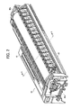
- FIG. 2 is a perspective view of a process cartridge incorporated in the image forming apparatus shown in FIG. 1 ;
- FIG. 3 is a cross-sectional view illustrating a main part of the process cartridge along line A-A shown in FIG. 2 ;
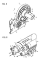
- FIG. 4 is a schematic perspective view of drive units according to an embodiment as viewed from the side of a development gear
- FIG. 5 is a perspective view of the drive unit as viewed from the side of a development clutch in FIG. 4 ;
- FIG. 6 is a partial perspective view of the process cartridge connected to the drive unit according to an embodiment as viewed from the side of a development roller;
- FIG. 7 is a partial perspective view of the drive unit shown in FIG. 6 as viewed from the side of a toner discharge coil.
- FIG. 1 a multicolor image forming apparatus according to an embodiment of the present invention is described.
- FIG. 1 is a schematic view of an image forming apparatus 100 according to an embodiment of the present invention.
- FIG. 2 is a perspective view of a process cartridge 30 removably mounted to a body of the image forming apparatus 100 shown in FIG. 1 .
- the image forming apparatus 100 is a socalled tandem image forming apparatus and includes drum-shaped photoreceptors 1Y, 1C, 1M, and 1B serving as image bearers on which toner images are formed, arranged in parallel to each other in the direction indicated by arrow A shown in FIG. 1 , in which an endless intermediate transfer belt 3 travels.
- the intermediate transfer belt 3 is stretched around support rollers 11A, 11B, 11C, and 11D. As one of the support rollers 11A through 11D rotates, the intermediate transfer belt 1 rotates in the direction indicated by arrow A.
- the toner images formed on the photoreceptors 1Y, 1C, 1 M, and 1B are transferred therefrom and superimposed one on another on the intermediate transfer belt 3, thus forming a multicolor image.
- a charging roller 4 to charge a surface of the photoreceptor 1 uniformly, a development device 2 to develop an electrostatic latent image formed on the photoreceptor 1 with toner into a toner image, and a cleaning unit 9 are provided.
- the cleaning unit 9 removes toner remaining (hereinafter “residual toner") on the photoreceptor 1 after a primary-transfer roller 6 transfers the toner image therefrom.
- the components provided around the photoreceptor 1, namely, the charging roller 4, the development device 2, and the cleaning unit 9 can be housed in a common unit casing together with the photoreceptor 1, thus forming a process cartridge 30 shown in FIG. 2 for forming yellow, cyan, magenta, or black toner images.
- the photoreceptor 1, the charging roller 4, the development device 2, and the cleaning unit 9 can be installed and removed together at a time from the image forming apparatus 100 easily and securely with the relative positions among them maintained with a high degree of accuracy. It is not necessary that all of the charging roller 4, the development device 2, and the cleaning unit 9 are united with the photoreceptor 1 into the process cartridge 30, but at least one of them may be united to the photoreceptor 1.
- the image forming apparatus 100 further includes a pair of registration rollers 7, a fixing device 8 including a heating roller 8a and a pressure roller 8b, and a secondary-transfer roller 10.
- a fixing device 8 including a heating roller 8a and a pressure roller 8b
- a secondary-transfer roller 10 a secondary-transfer roller 10.
- reference characters LY, LC, LM, and LB represent laser beams (i.e., exposure light) to form electrostatic latent images on the respective photoreceptors 1
- reference character P represents a sheet serving as a recording medium.
- FIG. 3 is a cross-sectional view illustrating a main part of the process cartridge 30 along line A-A shown in FIG. 2 .
- the process cartridge 30 is constructed of a photoreceptor unit 40 and a development unit 41 (i.e., the development device 2).
- the photoreceptor unit 40 and the development unit 41 may be housed in a common unit casing as a single unit.
- the photoreceptor unit 40 includes the photoreceptor 1, the charging roller 4, and the cleaning unit 9.
- a rotary shaft 1b of the photoreceptor 1 is supported by side plates 30a and 30b of the process cartridge 30 such that the photoreceptor 1 is rotatable.
- the charging roller 4 rotates while sliding on both axial end portions of the outer circumferential surface 1a of the photoreceptor 1.
- Spacers 4b are provided to axial end portions of the charging roller 4 to secure a predetermined distance between a charging portion 4a and the outer circumferential surface 1a of the photoreceptor 1. With this configuration, the charging portion 4a can be contactless from the photoreceptor 1 while charging the outer circumferential surface 1a of the photoreceptor 1 uniformly.
- the charging roller 4 is rotatable with a rotary shaft 4c thereof supported by the side plates 30a and 30b of the process cartridge 30. As the photoreceptor 1 rotates, the spacers 4b rotate, and thus the charging roller 4 rotates. It is to be noted that, alternatively, the charging roller 4 may be driven by a driving motor although the charging roller 4 in the present embodiment is not designed so.
- the development device 2 contains two-component developer including negatively charged toner and magnetic carrier in the present embodiment.
- the development device 2 includes a development roller 2a, rotary conveyance screws 2b to agitate and supply developer to the development roller 2a, and a development doctor 2c to adjust the amount of developer on the development roller 2a.
- the development roller 2a includes a stationary magnet 2a2 and a development sleeve 2a1 that rotates around the magnet 2a2. As the development roller 2a rotates, developer particles are caused to stand on end on thereon, and toner is supplied to the outer circumferential surface 1a of the photoreceptor 1.
- Developer is agitated and charged through triboelectric charging by the conveyance screws 2b, after which developer is supplied to the development roller 2a.
- the development doctor 2c adjusts a layer thickness of toner carried on the development roller 2a
- the developer is transported to a development position facing the photoreceptor 1, where toner is supplied to the electrostatic latent image formed on the photoreceptor 1.
- developer is returned inside the development unit 41 as the development roller 2a rotates.
- the cleaning unit 9, housed in the photoreceptor unit 40 includes a cleaning roller 9a to remove residual toner T from the outer circumferential surface 1a of the photoreceptor 1.
- the cleaning roller 9a includes a rotary shaft 9a1 and a toner remover 9a2, such as a fur brush or sponge, attached to the rotary shaft 9a1.
- the cleaning roller 9a can remove residual toner T from the photoreceptor 1 by rotating in a direction counter to the direction in which the surface of the photoreceptor 1 moves.
- the cleaning unit 9 further includes a cleaning blade 9b to scrape off residual toner T from the photoreceptor 1 by contacting slidingly the photoreceptor 1 and a toner discharge coil 9c through which toner removed by the cleaning blade 9b from the photoreceptor 1 (i.e., waste toner) is discharged outside.
- the toner discharge coil 9c includes a coil 9c2 winding around a rotary shaft 9c1. As the rotary shaft 9c1 rotates, waste toner is transported in the direction of winding of the coil 9c2. Thus, the residual toner T is removed by the cleaning blade 9b from the photoreceptor 1 and transported through the toner discharge coil 9c to a waste toner container.
- the photoreceptor 1 can serve as a drum-shaped first rotary member, and the cleaning roller 9a and the toner discharge coil 9c, disposed around the photoreceptor 1 and housed in a common unit casing (i.e., the photoreceptor unit 40), can serve as second rotary members.
- image formation in the image forming apparatus 100 is described below.
- the photoreceptor 1 is rotated in the direction indicated by arrow shown in FIG. 1 , and the charging roller 4 charges the outer circumferential surface 1a of the rotating photoreceptor 1 uniformly.
- a writing unit directs the laser beam L to the charged outer circumferential surface 1a of the photoreceptor 1, thus forming an electrostatic latent image for the corresponding color.
- the development device 2 supplies toner to the electrostatic latent image formed on the photoreceptor 1, developing it into a toner image.
- Transfer bias voltages are applied to the primary-transfer rollers 6, thereby transferring the toner images from the respective photoreceptors 1 sequentially and superimposing them on the intermediate transfer belt 3.
- a multicolor toner image is formed.
- the multicolor toner image is then transferred from the intermediate transfer belt 3 by the secondary-transfer roller 10 onto a sheet P of recording media, forwarded by the pair of registration rollers 7, timed to coincide with the multicolor toner image.
- the fixing device 8 fixes the toner image on the sheet P with heat from the heating roller 8a and pressure from the pressure roller 8b, after which the sheet P is output from the image forming apparatus 100.
- the respective photoreceptors 1 from which the toner images are transferred are cleaned by the cleaning units 9 and charged by the charging rollers 4 as a preparation for subsequent image formation.
- embodiments of the present invention are not limited thereto but can be, for example, monochrome image forming apparatuses including a single process cartridge for black. Additionally, although the description above concerns intermediate-transfer image formation using the intermediate transfer belt 3, embodiments of the present invention can be direct-transfer image forming apparatuses in which toner images formed on photoreceptors are transferred directly onto sheets of recording media transported by an endless conveyance belt.
- FIG. 4 is a schematic perspective view of drive units according to an embodiment as viewed from the side of a development gear.
- FIG. 5 is a perspective view of the drive units as viewed from the side of a development clutch in FIG. 4 .
- a photoreceptor drive unit 51 drives the first rotary member, namely, the photoreceptor 1, as well as the second rotary members, namely, the cleaning roller 9a and the toner discharge coil 9c, provided around the photoreceptor 1, housed in the photoreceptor unit 40.
- the photoreceptor drive unit 51 includes a photoreceptor motor 52 serving as a drive source, an output gear 52a (output gear) driven by the photoreceptor motor 52, a large-diameter gear 53 (first gear) larger in diameter than the output gear 52a, a small-diameter gear 54 (second gear) smaller in diameter than the large-diameter gear 53, and a first female joint 55 (first joint member).
- the large-diameter gear 53 is designed to mesh with the output gear 52a and decelerate outputs from the output gear 52a by being driven thereby.
- the small-diameter gear 54 is united to a first side of the large-diameter gear 53, specifically, united to a center of rotation (or axial center) of the large-diameter gear 53.
- the first female joint 55 projects to the photoreceptor 1 from a side of the small-diameter gear 54 coaxially with the small-diameter gear 54. Specifically, the first female joint 55 projects from a center of rotation (or axial center) of the small-diameter gear 54.
- the first female joint 55 is coupled to a rotation center of the photoreceptor 1.
- the first side of the large-diameter gear 53 faces the photoreceptor 1.
- the photoreceptor drive unit 51 further includes a cleaning driven gear 56 (driven gear), smaller in diameter than the large-diameter gear 53, and a third female joint 57 (second joint) projecting toward the photoreceptor 1 from a first side of the cleaning driven gear 56 coaxially.
- the third female joint 57 projects from an axial center of the cleaning driven gear 56.
- the cleaning driven gear 56 meshes with the small-diameter gear 54 and is driven thereby.
- the third female joint 57 is coupled to a center of rotation of the cleaning roller 9a.
- Gear tooth are cut in an output shaft 52-1 of the photoreceptor motor 52, thereby forming the output gear 52a.
- the drive force from the photoreceptor motor 52 is transmitted via the output gear 52a to the large-diameter gear 53.
- the drive force is then transmitted from the large-diameter gear 53 via the first female joint 55, which rotates together with the large-diameter gear 53, to a first male joint 31 (shown in FIG. 6 ) that rotates the photoreceptor 1.
- the first female joint 55 can be a female joint member having an involute spline shape, for example.
- the drive force from the photoreceptor motor 52 is decelerated a single step and is transmitted directly to the photoreceptor 1.
- the drive force from the photoreceptor motor 52 may be decelerated two steps or further before transmitted to the photoreceptor 1.
- the large-diameter gear 53 can be a multistage gear having the small-diameter gear 54 at the axial center thereof.
- the drive force from the photoreceptor motor 52 is transmitted also to the cleaning driven gear 56 via the small-diameter gear 54 rotating integrally with the large-diameter gear 53.
- the drive force is then transmitted from the cleaning driven gear 56 via the third female joint 57 that rotates integrally with the cleaning driven gear 56 to a third male joint 36 (shown in FIGS. 6 and 7 ) that rotates together or integrally with the cleaning roller 9a.
- the third male joint 36 rotates, further the toner discharge coil 9c is rotated.
- the third female joint 57 can be a female joint member having an involute spline shape, for example.
- a small-module gear having small teeth pitch is used as the large-diameter gear 53.
- This configuration can reduce the cycle of banding or color unevenness, making banding or color unevenness less noticeable in output images even if velocity fluctuations in teeth mesh cycle are reflected on the photoreceptor 1.
- the development roller 2a and the conveyance screws 2b, housed in the development unit 41, are driven by the development drive unit 61.
- the development drive unit 61 includes a development motor 62 serving as a drive source, an output gear 62a (development motor output gear) driven by the development motor 62, a development drive gear 63 larger in diameter than the output gear 62a, a development connection gear 64 provided to a first side of the development drive gear 63, coaxially with the development drive gear 63, a development driven gear 65 that meshes with the development connection gear 64 and is driven thereby, and a second female joint 66.
- the development drive gear 63 is designed to mesh with the output gear 62a and decelerate outputs from the output gear 62a by being driven thereby.
- the development connection gear 64 is larger in diameter than the development drive gear 63.
- the second female joint 66 projects coaxially from an axial center portion on a side of the development driven gear 65.
- Gear tooth are cut in an output shaft of the development motor 62, and thus the output shafts serves as the output gear 62a.
- the drive force from the development motor 62 is transmitted via the output gear 62a to the development drive gear 63 and to the development connection gear 64, which rotates integrally with the development drive gear 63. Further, the drive force is transmitted from the development connection gear 64 to the development driven gear 65. As the development driven gear 65 rotates, the drive force is further transmitted to the second female joint 66 rotating together with the development driven gear 65.
- the second female joint 66 can be a female joint member having an involute spline shape, for example.
- the second female joint 66 transmits the drive force to a second male joint 32 (shown in FIGS. 6 and 7 ) of the development device 2. Rotation of the second male joint 32 drives the development roller 2a and the conveyance screws 2b.
- FIG. 6 is a partial perspective view of the process cartridge 30 connected to the drive unit according to an embodiment as viewed from the development roller 2a.
- FIG. 7 is a partial perspective view of the drive unit shown in FIG. 6 as viewed from the toner discharge coil 9c.
- the development roller 2a, the conveyance screws 2b, the cleaning roller 9a (shown in FIG. 3 ), and the toner discharge coil 9c (rotary members) are provided around the photoreceptor 1 in the process cartridge 30.
- the rotary shafts of these rotary members are rotatably supported by the side plates 30a and 30b (shown in FIG. 2 ) of the process cartridge 30, retained in parallel to the rotary shaft 1b of the photoreceptor 1.
- the first male joint 31, having an involute spline shape, projects from the rotary shaft 1b of the photoreceptor 1 on the side of the side plate 30b.
- the first male joint 31 is connected to the rotary shaft 1b coaxially and rotates together with the photoreceptor 1.
- the second male joint 32 having an involute spline shape, for rotating the development roller 2a and the conveyance screws 2b, projects on the side of the side plate 30b (shown in FIG. 2 ).
- the second male joint 32 is supported rotatably by the side plate 30b (shown in FIG. 2 ).
- a first rotation gear 32a is attached coaxially to the second male joint 32
- a second rotation gear 33 is attached coaxially to a rotary shaft of the development roller 2a. With the second rotation gear 33 meshing with the first rotation gear 32a, the development roller 2a can rotate as the second male joint 32 rotates.
- a third rotation gear 34 provided coaxially with the rotary shaft 2b1 of the conveyance screws 2b meshes with the first rotation gear 32a, and the conveyance screw 2b rotates as the second male joint 32 rotates. Coupling in this case is similar to the coupling of the first male joint 31 fitted in the first female joint 55 of the photoreceptor drive unit 51.
- the second male joint 32 is inserted in the direction indicated by arrow Y (hereinafter "direction Y") into the second female joint 66 of the development drive unit 61.
- direction Y hereinafter "direction Y"
- the third male joint 36 having an involute spline shape, projects from one end of the cleaning roller 9a (shown in FIG. 3 ) on the side of the side plate 30b (shown in FIG. 2 ), coaxially with the rotary shaft 9a1 of the cleaning roller 9a.
- the third male joint 36 is supported rotatably by the side plate 30b (shown in FIG. 2 ).
- the cleaning roller 9a is designed to rotate as the third male joint 36 rotates.
- a fourth rotation gear 36a is fixed coaxially with a rotation axis of the third male joint 36 and positioned between the third male joint 36 and the toner remover 9a2.
- the fourth rotation gear 36a meshes with a fifth rotation gear 37 serving as an intermediate gear, and rotation of the third male joint 36 is transmitted via the fourth rotation gear 36a to the fifth rotation gear 37.
- the fifth rotation gear 37 meshes with a sixth rotation gear 38 provided coaxially with the rotary shaft 9c1 of the toner discharge coil 9c, and the toner discharge coil 9c rotates as the third male joint 36 rotates.
- Coupling in this case is similar to the coupling of the first male joint 31 fitted in the first female joint 55 of the photoreceptor drive unit 51. Specifically, as shown in FIGS.
- the third male joint 36 is inserted in the direction indicated by arrow Z (hereinafter "direction Z") into the third female joint 57 of the photoreceptor drive unit 51.
- direction Z the direction indicated by arrow Z
- the third male joint 36 fitted in the third female joint 57 rotation force from the photoreceptor motor 52 can be transmitted to the fourth rotation gear 36a. Accordingly, the rotation force transmitted to the fourth rotation gear 36a can rotate the cleaning roller 9a and the toner discharge coil 9c smoothly inside the process cartridge 30.
- the charging roller 4 is rotated by rotation of the photoreceptor 1 in the above-described configuration
- the charging roller 4 may be rotated by a drive force.
- the drive force is given from not the photoreceptor 1 via, for example, a flange-shaped gear provided to an end of the photoreceptor 1 but an element outside the process cartridge 30.
- male and female shapes of the above-described involute spline shapes can be reversed.
- the rotary members such as the cleaning roller 9a and the toner discharge coil 9c, disposed around the photoreceptor 1 receive the driving force from the third female joint 57 projecting from the cleaning driven gear 56 that meshes with the small-diameter gear 54 united to the axial center of the large-diameter gear 53.
- This configuration can obviate the need for supply of drive force from a flange-shaped gear provided to one end of the photoreceptor 1.
- Supplying drive force from the flange-shaped gear requires a drive transmission route from a large-diameter gear to a mating gear, and to a brush gear meshing with a flange gear coaxial with the mating gear.
- the drive force is transmitted from a large-diameter gear to a brush gear meshing with a small-diameter gear coaxial with the large-diameter gear, thus eliminating the flange gear and an element mating with the brush gear.
- gear meshing frequency is less reflected on the photoreceptor 1. Therefore, the possibility of occurrence of banding can be reduced.
- this configuration occupies a smaller space because the cleaning driven gear 56 is shaped to fall inside the face (projected area) of the large-diameter gear 53.
- the cleaning roller 9a and the toner discharge coil 9c receive the drive force transmitted through a joint structure, which is effective as the drive force can be transmitted with influence of gear meshing vibration on the photoreceptor 1 reduced or eliminated.
- the joint structure having involute spline shapes are effective to prevent reflection of gear meshing vibration on the photoreceptor 1.
- the joint structure having involute spline shapes are effective to prevent reflection of gear meshing vibration on the photoreceptor 1.
- the driving force for driving the rotary members namely, the cleaning roller 9a and the toner discharge coil 9c, housed in the photoreceptor unit 40 together with the photoreceptor 1 are transmitted from the photoreceptor motor 52 via the large-diameter gear 53 (first gear), the small-diameter gear 54 (second gear), the cleaning driven gear 56, and the third female joint 57 (second joint member).
- the large-diameter gear 53 and the small-diameter gear 54 are coaxial with each other, forming a multistage gear, and the cleaning driven gear 56 and the third female joint 57 are coaxial with each other similarly.
- the cleaning driven gear 56 (driven gear) engages the small-diameter gear 54 (second gear) that rotates coaxially with the large-diameter gear 53 (first gear) and thus receives drive force therefrom.
- the train of driving elements from the large-diameter gear 53 to the third female joint 57 can be disposed within the area (projected area) in the radial direction of the large-diameter gear 53, thus reducing the space necessary to accommodate the train of driving elements for the rotary members.
- the driving force for the rotary members can be transmitted through meshing of gears, without pulleys or belts. Thus, the number of components can be reduced.
- the cleaning roller 9a or the toner discharge coil 9c, or both are given driving force from the development motor 62 via a train of driving elements thereof, it requires a number of connections and a larger space.
- the above-described configuration can eliminate such disadvantages.
- the cleaning roller 9a and the toner discharge coil 9c are given driving force from the driving source (photoreceptor motor 52) identical to that for the photoreceptor 1.
- the cleaning driven gear 56 and the third female joint 57 both to transmit driving force from outside the process cartridge 30 to the cleaning roller 9a and the toner discharge coil 9c, are positioned within the area (projected area) of the large-diameter gear 53 in the radial direction, the configuration can be simple, and can be disposed within a smaller space.
- At least one of the rotary members disposed around the image bearer is given driving force from the second joint member projecting from axial center (or center of rotation) of the driven gear.
- the driven gear engages the second gear that rotates coaxially with the first gear, and thus driving force from the first gear can be transmitted to the driven gear and further to the rotary member. Since the driven gear is shaped to occupy only an area inside the area of the first gear in the radial direction thereof, space necessary for drive connection for the rotary member can be reduced.
Landscapes
- Engineering & Computer Science (AREA)
- Computer Vision & Pattern Recognition (AREA)
- Physics & Mathematics (AREA)
- General Physics & Mathematics (AREA)
- Electrophotography Configuration And Component (AREA)
Abstract
Description
- The present invention generally relates to a drive unit for an image forming apparatus, such as a copier, a printer, a facsimile machine, or a multifunction machine including at least two of these functions; and an electrophotographic image forming apparatus and a process cartridge that incorporates a drive unit.
- Electrophotographic image forming apparatuses generally include a photoreceptor drum serving as an image bearer and rotary members that rotate around the photoreceptor drum, namely, a cleaning roller, a charging roller, and the like. The image bearer and such rotary members are rotated by a drive force transmitted from a drive source such as a motor.
- For example, a structure proposed in
JP-2010-139846-A - In this structure, a drive force output from the output gear is transmitted to the image bearer and the rotary member through separate transmission routes. Accordingly, drive connections to transmit the drive force to the rotary members can increase in number, occupying a larger space inside the apparatus.
- It is a general object of the present invention to provide an improved and useful drive unit and an image forming apparatus in which the above-described problems are eliminated.
- In order to achieve the above-described object, there is provided a drive unit according to claim 1. Advantageous embodiments are defined by the dependent claims.
- Advantageously, a drive unit for rotating a first rotary member and a second rotary member disposed around the first rotary member includes a drive source, an output gear driven by the drive source, a first gear to engage the output gear, a first joint member projecting from a rotation center of the first gear coaxially with the first gear and coupled to a rotation center of the first rotary member, a second gear disposed between the first gear and the first joint member and connected to the first gear and the first joint member coaxially therewith, a driven gear to engage the second gear to be driven thereby, and a second joint member projecting from a rotation center of the driven gear coaxially in a direction in which the first joint member projects and connected to a rotation center of the second rotary member. The first gear is greater in diameter than the output gear, and the second gear is smaller in diameter than the first gear. The driven gear is smaller in diameter than the first gear and disposed within an area in a radial direction of the first gear.
- Advantageously, an image forming apparatus includes an image bearer, a rotary member disposed around the image bearer, and the above-described drive unit to drive the image bearer and the rotary member.
- Advantageously, the image bearer and the rotary member driven by the drive unit are housed in a common unit casing of a process cartridge.
- A more complete appreciation of the disclosure and many of the attendant advantages thereof will be readily obtained as the same becomes better understood by reference to the following detailed description when considered in connection with the accompanying drawings, wherein:
-
FIG. 1 is a schematic view of an image forming apparatus according to an embodiment of the present invention; -
FIG. 2 is a perspective view of a process cartridge incorporated in the image forming apparatus shown inFIG. 1 ; -
FIG. 3 is a cross-sectional view illustrating a main part of the process cartridge along line A-A shown inFIG. 2 ; -
FIG. 4 is a schematic perspective view of drive units according to an embodiment as viewed from the side of a development gear; -
FIG. 5 is a perspective view of the drive unit as viewed from the side of a development clutch inFIG. 4 ; -
FIG. 6 is a partial perspective view of the process cartridge connected to the drive unit according to an embodiment as viewed from the side of a development roller; and -
FIG. 7 is a partial perspective view of the drive unit shown inFIG. 6 as viewed from the side of a toner discharge coil. - In describing preferred embodiments illustrated in the drawings, specific terminology is employed for the sake of clarity. However, the disclosure of this patent specification is not intended to be limited to the specific terminology so selected, and it is to be understood that each specific element includes all technical equivalents that operate in a similar manner and achieve a similar result.
- Referring now to the drawings, wherein like reference numerals designate identical or corresponding parts throughout the several views thereof, and particularly to
FIG. 1 , a multicolor image forming apparatus according to an embodiment of the present invention is described. - It is to be noted that the suffixes Y, M, C, and B attached to each reference numeral indicate only that components indicated thereby are used for forming yellow, magenta, cyan, and black images, respectively, and hereinafter may be omitted when color discrimination is not necessary.
-
FIG. 1 is a schematic view of animage forming apparatus 100 according to an embodiment of the present invention.FIG. 2 is a perspective view of aprocess cartridge 30 removably mounted to a body of theimage forming apparatus 100 shown inFIG. 1 . - The
image forming apparatus 100 according to the present embodiment is a socalled tandem image forming apparatus and includes drum-shaped photoreceptors FIG. 1 , in which an endlessintermediate transfer belt 3 travels. - The
intermediate transfer belt 3 is stretched aroundsupport rollers support rollers 11A through 11D rotates, the intermediate transfer belt 1 rotates in the direction indicated by arrow A. The toner images formed on thephotoreceptors intermediate transfer belt 3, thus forming a multicolor image. - Around the photoreceptor 1, a
charging roller 4 to charge a surface of the photoreceptor 1 uniformly, adevelopment device 2 to develop an electrostatic latent image formed on the photoreceptor 1 with toner into a toner image, and acleaning unit 9 are provided. Thecleaning unit 9 removes toner remaining (hereinafter "residual toner") on the photoreceptor 1 after a primary-transfer roller 6 transfers the toner image therefrom. - The components provided around the photoreceptor 1, namely, the
charging roller 4, thedevelopment device 2, and thecleaning unit 9 can be housed in a common unit casing together with the photoreceptor 1, thus forming aprocess cartridge 30 shown inFIG. 2 for forming yellow, cyan, magenta, or black toner images. Thus, the photoreceptor 1, thecharging roller 4, thedevelopment device 2, and thecleaning unit 9 can be installed and removed together at a time from theimage forming apparatus 100 easily and securely with the relative positions among them maintained with a high degree of accuracy. It is not necessary that all of thecharging roller 4, thedevelopment device 2, and thecleaning unit 9 are united with the photoreceptor 1 into theprocess cartridge 30, but at least one of them may be united to the photoreceptor 1. - In
FIG. 1 , theimage forming apparatus 100 further includes a pair ofregistration rollers 7, afixing device 8 including aheating roller 8a and apressure roller 8b, and a secondary-transfer roller 10. It is to be noted that, inFIG. 1 , reference characters LY, LC, LM, and LB represent laser beams (i.e., exposure light) to form electrostatic latent images on the respective photoreceptors 1, and reference character P represents a sheet serving as a recording medium. -
FIG. 3 is a cross-sectional view illustrating a main part of theprocess cartridge 30 along line A-A shown inFIG. 2 . - In the configuration shown in
FIGS. 2 and3 , theprocess cartridge 30 is constructed of aphotoreceptor unit 40 and a development unit 41 (i.e., the development device 2). Thephotoreceptor unit 40 and thedevelopment unit 41 may be housed in a common unit casing as a single unit. - The
photoreceptor unit 40 includes the photoreceptor 1, thecharging roller 4, and thecleaning unit 9. Arotary shaft 1b of the photoreceptor 1 is supported byside plates process cartridge 30 such that the photoreceptor 1 is rotatable. Thecharging roller 4 rotates while sliding on both axial end portions of the outercircumferential surface 1a of the photoreceptor 1.Spacers 4b are provided to axial end portions of thecharging roller 4 to secure a predetermined distance between acharging portion 4a and the outercircumferential surface 1a of the photoreceptor 1. With this configuration, thecharging portion 4a can be contactless from the photoreceptor 1 while charging the outercircumferential surface 1a of the photoreceptor 1 uniformly. Thecharging roller 4 is rotatable with arotary shaft 4c thereof supported by theside plates process cartridge 30. As the photoreceptor 1 rotates, thespacers 4b rotate, and thus thecharging roller 4 rotates. It is to be noted that, alternatively, thecharging roller 4 may be driven by a driving motor although thecharging roller 4 in the present embodiment is not designed so. - The
development device 2 contains two-component developer including negatively charged toner and magnetic carrier in the present embodiment. Thedevelopment device 2 includes adevelopment roller 2a,rotary conveyance screws 2b to agitate and supply developer to thedevelopment roller 2a, and adevelopment doctor 2c to adjust the amount of developer on thedevelopment roller 2a. Thedevelopment roller 2a includes a stationary magnet 2a2 and a development sleeve 2a1 that rotates around the magnet 2a2. As thedevelopment roller 2a rotates, developer particles are caused to stand on end on thereon, and toner is supplied to the outercircumferential surface 1a of the photoreceptor 1. - Developer is agitated and charged through triboelectric charging by the
conveyance screws 2b, after which developer is supplied to thedevelopment roller 2a. After thedevelopment doctor 2c adjusts a layer thickness of toner carried on thedevelopment roller 2a, the developer is transported to a development position facing the photoreceptor 1, where toner is supplied to the electrostatic latent image formed on the photoreceptor 1. After toner therein is thus consumed, developer is returned inside thedevelopment unit 41 as thedevelopment roller 2a rotates. - As shown in
FIG. 3 , thecleaning unit 9, housed in thephotoreceptor unit 40, includes acleaning roller 9a to remove residual toner T from the outercircumferential surface 1a of the photoreceptor 1. Thecleaning roller 9a includes a rotary shaft 9a1 and a toner remover 9a2, such as a fur brush or sponge, attached to the rotary shaft 9a1. For example, thecleaning roller 9a can remove residual toner T from the photoreceptor 1 by rotating in a direction counter to the direction in which the surface of the photoreceptor 1 moves. - The
cleaning unit 9 further includes acleaning blade 9b to scrape off residual toner T from the photoreceptor 1 by contacting slidingly the photoreceptor 1 and atoner discharge coil 9c through which toner removed by thecleaning blade 9b from the photoreceptor 1 (i.e., waste toner) is discharged outside. Thetoner discharge coil 9c includes a coil 9c2 winding around a rotary shaft 9c1. As the rotary shaft 9c1 rotates, waste toner is transported in the direction of winding of the coil 9c2. Thus, the residual toner T is removed by thecleaning blade 9b from the photoreceptor 1 and transported through thetoner discharge coil 9c to a waste toner container. - Thus, in the present embodiment, the photoreceptor 1 can serve as a drum-shaped first rotary member, and the
cleaning roller 9a and thetoner discharge coil 9c, disposed around the photoreceptor 1 and housed in a common unit casing (i.e., the photoreceptor unit 40), can serve as second rotary members. - Referring to
FIG. 1 , image formation in theimage forming apparatus 100 is described below. - Initially the photoreceptor 1 is rotated in the direction indicated by arrow shown in
FIG. 1 , and the chargingroller 4 charges the outercircumferential surface 1a of the rotating photoreceptor 1 uniformly. Then, a writing unit directs the laser beam L to the charged outercircumferential surface 1a of the photoreceptor 1, thus forming an electrostatic latent image for the corresponding color. Then, thedevelopment device 2 supplies toner to the electrostatic latent image formed on the photoreceptor 1, developing it into a toner image. - Transfer bias voltages are applied to the primary-transfer rollers 6, thereby transferring the toner images from the respective photoreceptors 1 sequentially and superimposing them on the
intermediate transfer belt 3. Thus, a multicolor toner image is formed. The multicolor toner image is then transferred from theintermediate transfer belt 3 by the secondary-transfer roller 10 onto a sheet P of recording media, forwarded by the pair ofregistration rollers 7, timed to coincide with the multicolor toner image. The fixingdevice 8 fixes the toner image on the sheet P with heat from theheating roller 8a and pressure from thepressure roller 8b, after which the sheet P is output from theimage forming apparatus 100. - Meanwhile, the respective photoreceptors 1 from which the toner images are transferred are cleaned by the
cleaning units 9 and charged by the chargingrollers 4 as a preparation for subsequent image formation. - It is to be noted that, although the description above concerns tandem-type multicolor image forming apparatus, embodiments of the present invention are not limited thereto but can be, for example, monochrome image forming apparatuses including a single process cartridge for black. Additionally, although the description above concerns intermediate-transfer image formation using the
intermediate transfer belt 3, embodiments of the present invention can be direct-transfer image forming apparatuses in which toner images formed on photoreceptors are transferred directly onto sheets of recording media transported by an endless conveyance belt. - Descriptions are given below of a drive route in the body and a drive transmission route to the photoreceptor 1, the
development roller 2a, theconveyance screws 2b, the cleaningroller 9a, thetoner discharge coil 9c, and the chargingroller 4 housed in theprocess cartridge 30 according to the present embodiment. - Initially, the drive route in the body is described with reference to
FIGS. 4 and5 .FIG. 4 is a schematic perspective view of drive units according to an embodiment as viewed from the side of a development gear.FIG. 5 is a perspective view of the drive units as viewed from the side of a development clutch inFIG. 4 . - A
photoreceptor drive unit 51 drives the first rotary member, namely, the photoreceptor 1, as well as the second rotary members, namely, the cleaningroller 9a and thetoner discharge coil 9c, provided around the photoreceptor 1, housed in thephotoreceptor unit 40. Thephotoreceptor drive unit 51 includes aphotoreceptor motor 52 serving as a drive source, anoutput gear 52a (output gear) driven by thephotoreceptor motor 52, a large-diameter gear 53 (first gear) larger in diameter than theoutput gear 52a, a small-diameter gear 54 (second gear) smaller in diameter than the large-diameter gear 53, and a first female joint 55 (first joint member). The large-diameter gear 53 is designed to mesh with theoutput gear 52a and decelerate outputs from theoutput gear 52a by being driven thereby. The small-diameter gear 54 is united to a first side of the large-diameter gear 53, specifically, united to a center of rotation (or axial center) of the large-diameter gear 53. The first female joint 55 projects to the photoreceptor 1 from a side of the small-diameter gear 54 coaxially with the small-diameter gear 54. Specifically, the first female joint 55 projects from a center of rotation (or axial center) of the small-diameter gear 54. The first female joint 55 is coupled to a rotation center of the photoreceptor 1. The first side of the large-diameter gear 53 faces the photoreceptor 1. - The
photoreceptor drive unit 51 further includes a cleaning driven gear 56 (driven gear), smaller in diameter than the large-diameter gear 53, and a third female joint 57 (second joint) projecting toward the photoreceptor 1 from a first side of the cleaning drivengear 56 coaxially. In particular, the third female joint 57 projects from an axial center of the cleaning drivengear 56. The cleaning drivengear 56 meshes with the small-diameter gear 54 and is driven thereby. The third female joint 57 is coupled to a center of rotation of the cleaningroller 9a. - It is to be noted that the term "mesh" or "meshes" used in this specification means that projections and recesses of two gears engage each other, and the term "fits" means that the shape of one object fully conforms to the shape of the other object.
- Gear tooth are cut in an output shaft 52-1 of the
photoreceptor motor 52, thereby forming theoutput gear 52a. The drive force from thephotoreceptor motor 52 is transmitted via theoutput gear 52a to the large-diameter gear 53. The drive force is then transmitted from the large-diameter gear 53 via the first female joint 55, which rotates together with the large-diameter gear 53, to a first male joint 31 (shown inFIG. 6 ) that rotates the photoreceptor 1. It is to be noted that the first female joint 55 can be a female joint member having an involute spline shape, for example. In the present embodiment, the drive force from thephotoreceptor motor 52 is decelerated a single step and is transmitted directly to the photoreceptor 1. Alternatively, the drive force from thephotoreceptor motor 52 may be decelerated two steps or further before transmitted to the photoreceptor 1. - Additionally, the large-
diameter gear 53 can be a multistage gear having the small-diameter gear 54 at the axial center thereof. The drive force from thephotoreceptor motor 52 is transmitted also to the cleaning drivengear 56 via the small-diameter gear 54 rotating integrally with the large-diameter gear 53. The drive force is then transmitted from the cleaning drivengear 56 via the third female joint 57 that rotates integrally with the cleaning drivengear 56 to a third male joint 36 (shown inFIGS. 6 and7 ) that rotates together or integrally with the cleaningroller 9a. As the third male joint 36 rotates, further thetoner discharge coil 9c is rotated. It is to be noted that the third female joint 57 can be a female joint member having an involute spline shape, for example. - It is to be noted that, in the present embodiment, a small-module gear having small teeth pitch is used as the large-
diameter gear 53. This configuration can reduce the cycle of banding or color unevenness, making banding or color unevenness less noticeable in output images even if velocity fluctuations in teeth mesh cycle are reflected on the photoreceptor 1. - Next, a
development drive unit 61 shown inFIGS. 4 and5 to transmit drive force to the rotary members in thedevelopment unit 41 is described below. - The
development roller 2a and theconveyance screws 2b, housed in thedevelopment unit 41, are driven by thedevelopment drive unit 61. Thedevelopment drive unit 61 includes adevelopment motor 62 serving as a drive source, anoutput gear 62a (development motor output gear) driven by thedevelopment motor 62, adevelopment drive gear 63 larger in diameter than theoutput gear 62a, adevelopment connection gear 64 provided to a first side of thedevelopment drive gear 63, coaxially with thedevelopment drive gear 63, a development drivengear 65 that meshes with thedevelopment connection gear 64 and is driven thereby, and a second female joint 66. Thedevelopment drive gear 63 is designed to mesh with theoutput gear 62a and decelerate outputs from theoutput gear 62a by being driven thereby. Thedevelopment connection gear 64 is larger in diameter than thedevelopment drive gear 63. The second female joint 66 projects coaxially from an axial center portion on a side of the development drivengear 65. - Gear tooth are cut in an output shaft of the
development motor 62, and thus the output shafts serves as theoutput gear 62a. The drive force from thedevelopment motor 62 is transmitted via theoutput gear 62a to thedevelopment drive gear 63 and to thedevelopment connection gear 64, which rotates integrally with thedevelopment drive gear 63. Further, the drive force is transmitted from thedevelopment connection gear 64 to the development drivengear 65. As the development drivengear 65 rotates, the drive force is further transmitted to the second female joint 66 rotating together with the development drivengear 65. It is to be noted that the second female joint 66 can be a female joint member having an involute spline shape, for example. - The second female joint 66 transmits the drive force to a second male joint 32 (shown in
FIGS. 6 and7 ) of thedevelopment device 2. Rotation of the second male joint 32 drives thedevelopment roller 2a and theconveyance screws 2b. - Referring to
FIGS. 6 and7 , descriptions are given below of a drive transmission route to the photoreceptor 1, thedevelopment roller 2a, theconveyance screws 2b, the cleaningroller 9a, and thetoner discharge coil 9c, which are housed in theprocess cartridge 30 and driven by the above-described drive units.FIG. 6 is a partial perspective view of theprocess cartridge 30 connected to the drive unit according to an embodiment as viewed from thedevelopment roller 2a.FIG. 7 is a partial perspective view of the drive unit shown inFIG. 6 as viewed from thetoner discharge coil 9c. - As shown in
FIGS. 6 and7 , thedevelopment roller 2a, theconveyance screws 2b, the cleaningroller 9a (shown inFIG. 3 ), and thetoner discharge coil 9c (rotary members) are provided around the photoreceptor 1 in theprocess cartridge 30. The rotary shafts of these rotary members are rotatably supported by theside plates FIG. 2 ) of theprocess cartridge 30, retained in parallel to therotary shaft 1b of the photoreceptor 1. The first male joint 31, having an involute spline shape, projects from therotary shaft 1b of the photoreceptor 1 on the side of theside plate 30b. The first male joint 31 is connected to therotary shaft 1b coaxially and rotates together with the photoreceptor 1. - Accordingly, as shown in
FIGS. 4 and6 , when the first male joint 31 of theprocess cartridge 30 is inserted in the direction indicated by arrow X (hereinafter "direction X") into the first female joint 55 of thephotoreceptor drive unit 51, the first male joint 31 can be connected to the first female joint 55 properly. Then, rotation force from thephotoreceptor motor 52 can be transmitted to the photoreceptor 1 via the first male joint 31. With this rotation force, the photoreceptor 1 can rotate smoothly inside theprocess cartridge 30. - Similarly, referring to
FIG. 6 , the second male joint 32, having an involute spline shape, for rotating thedevelopment roller 2a and theconveyance screws 2b, projects on the side of theside plate 30b (shown inFIG. 2 ). The second male joint 32 is supported rotatably by theside plate 30b (shown inFIG. 2 ). Afirst rotation gear 32a is attached coaxially to the second male joint 32, and asecond rotation gear 33 is attached coaxially to a rotary shaft of thedevelopment roller 2a. With thesecond rotation gear 33 meshing with thefirst rotation gear 32a, thedevelopment roller 2a can rotate as the second male joint 32 rotates. - Further, a
third rotation gear 34 provided coaxially with the rotary shaft 2b1 of the conveyance screws 2b meshes with thefirst rotation gear 32a, and theconveyance screw 2b rotates as the second male joint 32 rotates. Coupling in this case is similar to the coupling of the first male joint 31 fitted in the first female joint 55 of thephotoreceptor drive unit 51. Specifically, as shown inFIGS. 4 and6 , the second male joint 32 is inserted in the direction indicated by arrow Y (hereinafter "direction Y") into the second female joint 66 of thedevelopment drive unit 61. With the second male joint 32 fitted in the second female joint 66, rotation force from thedevelopment motor 62 can be transmitted to thefirst rotation gear 32a. Accordingly, the rotation force transmitted to thefirst rotation gear 32a can rotate thedevelopment roller 2a and the conveyance screws 2b smoothly inside theprocess cartridge 30. - Additionally, as shown in
FIG. 7 , the third male joint 36, having an involute spline shape, projects from one end of the cleaningroller 9a (shown inFIG. 3 ) on the side of theside plate 30b (shown inFIG. 2 ), coaxially with the rotary shaft 9a1 of the cleaningroller 9a. The third male joint 36 is supported rotatably by theside plate 30b (shown inFIG. 2 ). The cleaningroller 9a is designed to rotate as the third male joint 36 rotates. - A
fourth rotation gear 36a is fixed coaxially with a rotation axis of the third male joint 36 and positioned between the third male joint 36 and the toner remover 9a2. Thefourth rotation gear 36a meshes with afifth rotation gear 37 serving as an intermediate gear, and rotation of the third male joint 36 is transmitted via thefourth rotation gear 36a to thefifth rotation gear 37. Further, thefifth rotation gear 37 meshes with asixth rotation gear 38 provided coaxially with the rotary shaft 9c1 of thetoner discharge coil 9c, and thetoner discharge coil 9c rotates as the third male joint 36 rotates. Coupling in this case is similar to the coupling of the first male joint 31 fitted in the first female joint 55 of thephotoreceptor drive unit 51. Specifically, as shown inFIGS. 4 and6 , the third male joint 36 is inserted in the direction indicated by arrow Z (hereinafter "direction Z") into the third female joint 57 of thephotoreceptor drive unit 51. With the third male joint 36 fitted in the third female joint 57, rotation force from thephotoreceptor motor 52 can be transmitted to thefourth rotation gear 36a. Accordingly, the rotation force transmitted to thefourth rotation gear 36a can rotate thecleaning roller 9a and thetoner discharge coil 9c smoothly inside theprocess cartridge 30. - It is to be noted that, although the charging
roller 4 is rotated by rotation of the photoreceptor 1 in the above-described configuration, alternatively, the chargingroller 4 may be rotated by a drive force. In such a configuration, it is preferable that the drive force is given from not the photoreceptor 1 via, for example, a flange-shaped gear provided to an end of the photoreceptor 1 but an element outside theprocess cartridge 30. - Additionally, male and female shapes of the above-described involute spline shapes can be reversed.
- In the image forming apparatus according to the present embodiment, the rotary members, such as the cleaning
roller 9a and thetoner discharge coil 9c, disposed around the photoreceptor 1 receive the driving force from the third female joint 57 projecting from the cleaning drivengear 56 that meshes with the small-diameter gear 54 united to the axial center of the large-diameter gear 53. This configuration can obviate the need for supply of drive force from a flange-shaped gear provided to one end of the photoreceptor 1. Supplying drive force from the flange-shaped gear requires a drive transmission route from a large-diameter gear to a mating gear, and to a brush gear meshing with a flange gear coaxial with the mating gear. - Instead, in the present embodiment, the drive force is transmitted from a large-diameter gear to a brush gear meshing with a small-diameter gear coaxial with the large-diameter gear, thus eliminating the flange gear and an element mating with the brush gear. In other words, since the number of times of gear meshing in the drive transmission route is reduced from twice to once, gear meshing frequency is less reflected on the photoreceptor 1. Therefore, the possibility of occurrence of banding can be reduced.
- Additionally, this configuration occupies a smaller space because the cleaning driven
gear 56 is shaped to fall inside the face (projected area) of the large-diameter gear 53. - Additionally, the cleaning
roller 9a and thetoner discharge coil 9c receive the drive force transmitted through a joint structure, which is effective as the drive force can be transmitted with influence of gear meshing vibration on the photoreceptor 1 reduced or eliminated. In particular, the joint structure having involute spline shapes, as in the above-described embodiment, are effective to prevent reflection of gear meshing vibration on the photoreceptor 1. - In particular, the joint structure having involute spline shapes, as in the above-described embodiment, are effective to prevent reflection of gear meshing vibration on the photoreceptor 1.
- In the above-described embodiment, the driving force for driving the rotary members, namely, the cleaning
roller 9a and thetoner discharge coil 9c, housed in thephotoreceptor unit 40 together with the photoreceptor 1, are transmitted from thephotoreceptor motor 52 via the large-diameter gear 53 (first gear), the small-diameter gear 54 (second gear), the cleaning drivengear 56, and the third female joint 57 (second joint member). The large-diameter gear 53 and the small-diameter gear 54 are coaxial with each other, forming a multistage gear, and the cleaning drivengear 56 and the third female joint 57 are coaxial with each other similarly. The cleaning driven gear 56 (driven gear) engages the small-diameter gear 54 (second gear) that rotates coaxially with the large-diameter gear 53 (first gear) and thus receives drive force therefrom. - Accordingly, the train of driving elements from the large-
diameter gear 53 to the third female joint 57 can be disposed within the area (projected area) in the radial direction of the large-diameter gear 53, thus reducing the space necessary to accommodate the train of driving elements for the rotary members. Additionally, the driving force for the rotary members can be transmitted through meshing of gears, without pulleys or belts. Thus, the number of components can be reduced. - If the
cleaning roller 9a or thetoner discharge coil 9c, or both, are given driving force from thedevelopment motor 62 via a train of driving elements thereof, it requires a number of connections and a larger space. The above-described configuration can eliminate such disadvantages. - Additionally, in the above-described embodiment, the cleaning
roller 9a and thetoner discharge coil 9c are given driving force from the driving source (photoreceptor motor 52) identical to that for the photoreceptor 1. Simultaneously, since the cleaning drivengear 56 and the third female joint 57, both to transmit driving force from outside theprocess cartridge 30 to thecleaning roller 9a and thetoner discharge coil 9c, are positioned within the area (projected area) of the large-diameter gear 53 in the radial direction, the configuration can be simple, and can be disposed within a smaller space. - By contrast, if a gear disposed inside the projected area of the large-
diameter gear 53 is driven by an additional motor separate from thephotoreceptor motor 52 for driving the large-diameter gear 53, and the additional motor is disposed outside the projected area of the large-diameter gear 53, a part of the train of driving elements is positioned outside the projected area of the large-diameter gear 53. - As described above, in the above-described embodiment, at least one of the rotary members disposed around the image bearer is given driving force from the second joint member projecting from axial center (or center of rotation) of the driven gear. The driven gear engages the second gear that rotates coaxially with the first gear, and thus driving force from the first gear can be transmitted to the driven gear and further to the rotary member. Since the driven gear is shaped to occupy only an area inside the area of the first gear in the radial direction thereof, space necessary for drive connection for the rotary member can be reduced.
- This patent application is based on Japanese Patent Application Nos.
2011-249509 filed on November 15, 2011 2012-136064 filed on June 15,2012
Claims (5)
- A drive unit (51) for rotating a first rotary member (1) and a second rotary member (9a; 9c) disposed around the first rotary member (1), the drive unit (51) comprising:a drive source (52);an output gear (52a) driven by the drive source (52);a first gear (53) greater in diameter than the output gear (52a) and disposed to engage the output gear (52a);a first joint member (55) projecting from a rotation center of the first gear (53) coaxially with the first gear (53) and coupled to a rotation center of the first rotary member (1);a second gear (54) disposed between the first gear (53) and the first joint member (55) and connected to the first gear (53) and the first joint member (55) coaxially therewith, the second gear (54) smaller in diameter than the first gear (53);a driven gear (56) to engage the second gear (54) to be driven thereby, the driven gear (56) smaller in diameter than the first gear (53) and disposed within an area of the first gear (53) in a radial direction thereof; anda second joint member (57) projecting coaxially from a rotation center of the driven gear (56) in a direction in which the first joint member (55) projects and connected to a rotation center of the second rotary member (9a; 9c).
- The drive unit (51) according to claim 1, wherein the second joint member (57) has an involute spline shape.
- The drive unit (51) according to claim 1 or 2, wherein the first rotary member (1) is a drum-shaped image bearer.
- An image fanning apparatus (100) comprising:a drum-shaped image bearer (1);a rotary member (9a; 9c) disposed around the image bearer (1); andthe drive unit (51) according to claim 1, 2, or 3.
- A process cartridge (30) removably mounted in the image forming apparatus (100) according to claim 4, the process cartridge (30) comprising:the image bearer (1); andthe rotary member (9a; 9c) disposed around the image bearer (1) and housed in a unit casing together with the image bearer (1).
Applications Claiming Priority (2)
| Application Number | Priority Date | Filing Date | Title |
|---|---|---|---|
| JP2011249509 | 2011-11-15 | ||
| JP2012136064A JP5991037B2 (en) | 2011-11-15 | 2012-06-15 | Drive device, image forming apparatus, and process cartridge |
Publications (3)
| Publication Number | Publication Date |
|---|---|
| EP2597519A2 true EP2597519A2 (en) | 2013-05-29 |
| EP2597519A3 EP2597519A3 (en) | 2016-10-12 |
| EP2597519B1 EP2597519B1 (en) | 2020-10-21 |
Family
ID=47115466
Family Applications (1)
| Application Number | Title | Priority Date | Filing Date |
|---|---|---|---|
| EP12189502.3A Active EP2597519B1 (en) | 2011-11-15 | 2012-10-23 | Drive unit, and image forming apparatus and process cartridge incorporating same |
Country Status (4)
| Country | Link |
|---|---|
| US (1) | US8903278B2 (en) |
| EP (1) | EP2597519B1 (en) |
| JP (1) | JP5991037B2 (en) |
| CN (1) | CN103105757B (en) |
Families Citing this family (5)
| Publication number | Priority date | Publication date | Assignee | Title |
|---|---|---|---|---|
| JP6212911B2 (en) | 2012-05-17 | 2017-10-18 | 株式会社リコー | State determination device, image processing device, state determination method, and state determination program |
| US10171531B2 (en) | 2016-04-13 | 2019-01-01 | Viasat, Inc. | Continuing electronic media entertainment after completion of travel segment |
| JP6914620B2 (en) * | 2016-06-29 | 2021-08-04 | キヤノン株式会社 | Image forming device |
| JP6715151B2 (en) | 2016-09-29 | 2020-07-01 | 本田技研工業株式会社 | Clutch actuator |
| CN108957997B (en) * | 2018-07-27 | 2024-04-05 | 珠海天威飞马打印耗材有限公司 | Process cartridge |
Citations (1)
| Publication number | Priority date | Publication date | Assignee | Title |
|---|---|---|---|---|
| JP2010139846A (en) | 2008-12-12 | 2010-06-24 | Ricoh Co Ltd | Driving mechanism for image forming apparatus, image forming apparatus, and process cartridge |
Family Cites Families (32)
| Publication number | Priority date | Publication date | Assignee | Title |
|---|---|---|---|---|
| KR950007530B1 (en) * | 1991-11-26 | 1995-07-11 | 삼성전자주식회사 | Magnetic roller driving apparatus of a developer |
| US5689764A (en) * | 1995-05-24 | 1997-11-18 | Ricoh Company, Ltd. | Image forming apparatus and device for driving a contact type charging member |
| US5905927A (en) * | 1996-12-03 | 1999-05-18 | Minolta Co., Ltd. | Image forming apparatus and driving mechanism for image holding member |
| JP2000075765A (en) * | 1998-08-28 | 2000-03-14 | Matsushita Electric Ind Co Ltd | Color image forming equipment |
| JP3716716B2 (en) * | 2000-07-10 | 2005-11-16 | 富士ゼロックス株式会社 | Rotating body driving device and image forming apparatus using the same |
| JP2002207331A (en) * | 2001-01-09 | 2002-07-26 | Matsushita Electric Ind Co Ltd | Image forming device |
| JP3657530B2 (en) * | 2001-05-15 | 2005-06-08 | シャープ株式会社 | Image forming apparatus |
| JP4081662B2 (en) * | 2001-12-14 | 2008-04-30 | 富士ゼロックス株式会社 | Driving device and image forming apparatus using the same |
| JP2004109616A (en) | 2002-09-19 | 2004-04-08 | Seiko Epson Corp | Color image forming device |
| JP2004102020A (en) | 2002-09-11 | 2004-04-02 | Seiko Epson Corp | Color image forming device |
| US7155151B2 (en) * | 2002-11-20 | 2006-12-26 | Seiko Epson Corporation | Developer carrier, developing device, image forming apparatus and computer system |
| JP2004184439A (en) * | 2002-11-29 | 2004-07-02 | Seiko Epson Corp | Heat radiating device in developing cartridge and developing cartridge provided with the same |
| KR100644625B1 (en) * | 2004-09-06 | 2006-11-10 | 삼성전자주식회사 | A driving method of the developer driving device and an image forming apparatus having the same |
| JP4089689B2 (en) * | 2004-12-28 | 2008-05-28 | ブラザー工業株式会社 | Image forming apparatus and photosensitive drum unit |
| JP4270167B2 (en) * | 2005-05-20 | 2009-05-27 | ブラザー工業株式会社 | Image forming apparatus |
| US7526231B2 (en) * | 2005-08-08 | 2009-04-28 | Ricoh Company, Ltd. | Driven unit installable in an image forming apparatus with a reduced force |
| JP4857739B2 (en) * | 2005-11-30 | 2012-01-18 | ブラザー工業株式会社 | Image forming apparatus and developing cartridge |
| JP4778807B2 (en) * | 2006-02-17 | 2011-09-21 | 株式会社リコー | Image forming apparatus |
| JP2007219317A (en) * | 2006-02-17 | 2007-08-30 | Brother Ind Ltd | Image forming apparatus |
| JP4914620B2 (en) * | 2006-02-28 | 2012-04-11 | 株式会社リコー | Image forming apparatus |
| US7693468B2 (en) * | 2006-04-28 | 2010-04-06 | Ricoh Company, Ltd. | Image forming apparatus capable of effectively forming a quality color image |
| JP4651131B2 (en) * | 2006-12-11 | 2011-03-16 | キヤノン株式会社 | Process cartridge |
| JP5229604B2 (en) * | 2007-01-12 | 2013-07-03 | 株式会社リコー | Image forming apparatus |
| KR20080081668A (en) * | 2007-03-06 | 2008-09-10 | 삼성전자주식회사 | Image forming apparatus and fixing unit provided therein |
| KR101222579B1 (en) * | 2007-03-23 | 2013-01-16 | 삼성전자주식회사 | Image forming apparatus |
| KR101059821B1 (en) * | 2007-03-26 | 2011-08-26 | 삼성전자주식회사 | Color image forming apparatus and image forming unit |
| JP2008262096A (en) | 2007-04-13 | 2008-10-30 | Ricoh Co Ltd | Image forming apparatus |
| JP5152481B2 (en) * | 2007-09-14 | 2013-02-27 | 株式会社リコー | Drive transmission device, image forming apparatus using the same, and process cartridge |
| DE102008013983B3 (en) * | 2008-03-12 | 2009-08-13 | Jahnel-Kestermann Getriebewerke Gmbh & Co. Kg | Method for adjusting a tooth flank position of a toothed wheel, which is frictionally connected to a double helical pinion shaft |
| JP4845999B2 (en) * | 2009-05-15 | 2011-12-28 | 株式会社沖データ | Image forming apparatus |
| JP5445942B2 (en) * | 2009-12-25 | 2014-03-19 | 株式会社リコー | Drive transmission device, drive device, and image forming apparatus |
| JP5383523B2 (en) * | 2010-01-14 | 2014-01-08 | シャープ株式会社 | Rotation transmission mechanism of image forming apparatus |
-
2012
- 2012-06-15 JP JP2012136064A patent/JP5991037B2/en active Active
- 2012-10-18 US US13/654,881 patent/US8903278B2/en not_active Expired - Fee Related
- 2012-10-23 EP EP12189502.3A patent/EP2597519B1/en active Active
- 2012-11-07 CN CN201210441381.8A patent/CN103105757B/en not_active Expired - Fee Related
Patent Citations (1)
| Publication number | Priority date | Publication date | Assignee | Title |
|---|---|---|---|---|
| JP2010139846A (en) | 2008-12-12 | 2010-06-24 | Ricoh Co Ltd | Driving mechanism for image forming apparatus, image forming apparatus, and process cartridge |
Also Published As
| Publication number | Publication date |
|---|---|
| EP2597519B1 (en) | 2020-10-21 |
| JP5991037B2 (en) | 2016-09-14 |
| CN103105757B (en) | 2015-12-09 |
| CN103105757A (en) | 2013-05-15 |
| EP2597519A3 (en) | 2016-10-12 |
| JP2013127596A (en) | 2013-06-27 |
| US8903278B2 (en) | 2014-12-02 |
| US20130118303A1 (en) | 2013-05-16 |
Similar Documents
| Publication | Publication Date | Title |
|---|---|---|
| US8903277B2 (en) | Drive transmitter and image forming apparatus | |
| US7634213B2 (en) | Toner collecting device, image forming unit and image forming apparatus | |
| JP5424115B2 (en) | Drive transmission device and image forming apparatus | |
| JP5928887B2 (en) | Structure and image forming apparatus | |
| US8585537B2 (en) | Driving device and image forming apparatus | |
| EP2597519B1 (en) | Drive unit, and image forming apparatus and process cartridge incorporating same | |
| JP2014034995A (en) | Driving transmission device and image formation device | |
| JP2012013899A (en) | Developing device, process unit and image forming apparatus | |
| JP5268879B2 (en) | Drive transmission mechanism and image forming apparatus having the same | |
| JP2015194247A (en) | Drive transmission device and image forming device | |
| JPH1115275A (en) | Developing drive | |
| JP2001235970A (en) | Driving device for image carrier and image forming apparatus having the driving device | |
| JP6094795B2 (en) | Process unit and image forming apparatus | |
| JP3796474B2 (en) | Color image forming apparatus | |
| JP6697712B2 (en) | Drive device and image forming apparatus | |
| JP2002207331A (en) | Image forming device | |
| JP5167894B2 (en) | Image forming apparatus | |
| US9541883B2 (en) | Image forming apparatus | |
| JP2012233488A (en) | Planetary gear shifting mechanism, rotary driving device and image forming apparatus | |
| JP2010139846A (en) | Driving mechanism for image forming apparatus, image forming apparatus, and process cartridge | |
| JP2017003635A (en) | Drive device and image formation apparatus | |
| JP4635976B2 (en) | Image forming apparatus | |
| JP2007025731A (en) | Image carrier driving apparatus and image forming apparatus having the driving apparatus | |
| JP2015004874A (en) | Process unit and image forming apparatus | |
| JP2007264420A (en) | Image forming apparatus |
Legal Events
| Date | Code | Title | Description |
|---|---|---|---|
| PUAI | Public reference made under article 153(3) epc to a published international application that has entered the european phase |
Free format text: ORIGINAL CODE: 0009012 |
|
| 17P | Request for examination filed |
Effective date: 20121023 |
|
| AK | Designated contracting states |
Kind code of ref document: A2 Designated state(s): AL AT BE BG CH CY CZ DE DK EE ES FI FR GB GR HR HU IE IS IT LI LT LU LV MC MK MT NL NO PL PT RO RS SE SI SK SM TR |
|
| AX | Request for extension of the european patent |
Extension state: BA ME |
|
| PUAL | Search report despatched |
Free format text: ORIGINAL CODE: 0009013 |
|
| AK | Designated contracting states |
Kind code of ref document: A3 Designated state(s): AL AT BE BG CH CY CZ DE DK EE ES FI FR GB GR HR HU IE IS IT LI LT LU LV MC MK MT NL NO PL PT RO RS SE SI SK SM TR |
|
| AX | Request for extension of the european patent |
Extension state: BA ME |
|
| RIC1 | Information provided on ipc code assigned before grant |
Ipc: G03G 15/00 20060101AFI20160908BHEP Ipc: G03G 21/18 20060101ALI20160908BHEP |
|
| STAA | Information on the status of an ep patent application or granted ep patent |
Free format text: STATUS: EXAMINATION IS IN PROGRESS |
|
| 17Q | First examination report despatched |
Effective date: 20190516 |
|
| GRAP | Despatch of communication of intention to grant a patent |
Free format text: ORIGINAL CODE: EPIDOSNIGR1 |
|
| STAA | Information on the status of an ep patent application or granted ep patent |
Free format text: STATUS: GRANT OF PATENT IS INTENDED |
|
| INTG | Intention to grant announced |
Effective date: 20200512 |
|
| GRAS | Grant fee paid |
Free format text: ORIGINAL CODE: EPIDOSNIGR3 |
|
| GRAA | (expected) grant |
Free format text: ORIGINAL CODE: 0009210 |
|
| STAA | Information on the status of an ep patent application or granted ep patent |
Free format text: STATUS: THE PATENT HAS BEEN GRANTED |
|
| AK | Designated contracting states |
Kind code of ref document: B1 Designated state(s): AL AT BE BG CH CY CZ DE DK EE ES FI FR GB GR HR HU IE IS IT LI LT LU LV MC MK MT NL NO PL PT RO RS SE SI SK SM TR |
|
| REG | Reference to a national code |
Ref country code: GB Ref legal event code: FG4D |
|
| REG | Reference to a national code |
Ref country code: CH Ref legal event code: EP |
|
| REG | Reference to a national code |
Ref country code: IE Ref legal event code: FG4D |
|
| REG | Reference to a national code |
Ref country code: DE Ref legal event code: R096 Ref document number: 602012072867 Country of ref document: DE |
|
| REG | Reference to a national code |
Ref country code: AT Ref legal event code: REF Ref document number: 1326422 Country of ref document: AT Kind code of ref document: T Effective date: 20201115 |
|
| REG | Reference to a national code |
Ref country code: NL Ref legal event code: FP |
|
| REG | Reference to a national code |
Ref country code: AT Ref legal event code: MK05 Ref document number: 1326422 Country of ref document: AT Kind code of ref document: T Effective date: 20201021 |
|
| PG25 | Lapsed in a contracting state [announced via postgrant information from national office to epo] |
Ref country code: FI Free format text: LAPSE BECAUSE OF FAILURE TO SUBMIT A TRANSLATION OF THE DESCRIPTION OR TO PAY THE FEE WITHIN THE PRESCRIBED TIME-LIMIT Effective date: 20201021 Ref country code: RS Free format text: LAPSE BECAUSE OF FAILURE TO SUBMIT A TRANSLATION OF THE DESCRIPTION OR TO PAY THE FEE WITHIN THE PRESCRIBED TIME-LIMIT Effective date: 20201021 Ref country code: NO Free format text: LAPSE BECAUSE OF FAILURE TO SUBMIT A TRANSLATION OF THE DESCRIPTION OR TO PAY THE FEE WITHIN THE PRESCRIBED TIME-LIMIT Effective date: 20210121 Ref country code: PT Free format text: LAPSE BECAUSE OF FAILURE TO SUBMIT A TRANSLATION OF THE DESCRIPTION OR TO PAY THE FEE WITHIN THE PRESCRIBED TIME-LIMIT Effective date: 20210222 Ref country code: GR Free format text: LAPSE BECAUSE OF FAILURE TO SUBMIT A TRANSLATION OF THE DESCRIPTION OR TO PAY THE FEE WITHIN THE PRESCRIBED TIME-LIMIT Effective date: 20210122 |
|
| REG | Reference to a national code |
Ref country code: LT Ref legal event code: MG4D |
|
| PG25 | Lapsed in a contracting state [announced via postgrant information from national office to epo] |
Ref country code: PL Free format text: LAPSE BECAUSE OF FAILURE TO SUBMIT A TRANSLATION OF THE DESCRIPTION OR TO PAY THE FEE WITHIN THE PRESCRIBED TIME-LIMIT Effective date: 20201021 Ref country code: SE Free format text: LAPSE BECAUSE OF FAILURE TO SUBMIT A TRANSLATION OF THE DESCRIPTION OR TO PAY THE FEE WITHIN THE PRESCRIBED TIME-LIMIT Effective date: 20201021 Ref country code: LV Free format text: LAPSE BECAUSE OF FAILURE TO SUBMIT A TRANSLATION OF THE DESCRIPTION OR TO PAY THE FEE WITHIN THE PRESCRIBED TIME-LIMIT Effective date: 20201021 Ref country code: ES Free format text: LAPSE BECAUSE OF FAILURE TO SUBMIT A TRANSLATION OF THE DESCRIPTION OR TO PAY THE FEE WITHIN THE PRESCRIBED TIME-LIMIT Effective date: 20201021 Ref country code: IS Free format text: LAPSE BECAUSE OF FAILURE TO SUBMIT A TRANSLATION OF THE DESCRIPTION OR TO PAY THE FEE WITHIN THE PRESCRIBED TIME-LIMIT Effective date: 20210221 Ref country code: BG Free format text: LAPSE BECAUSE OF FAILURE TO SUBMIT A TRANSLATION OF THE DESCRIPTION OR TO PAY THE FEE WITHIN THE PRESCRIBED TIME-LIMIT Effective date: 20210121 Ref country code: AT Free format text: LAPSE BECAUSE OF FAILURE TO SUBMIT A TRANSLATION OF THE DESCRIPTION OR TO PAY THE FEE WITHIN THE PRESCRIBED TIME-LIMIT Effective date: 20201021 |
|
| REG | Reference to a national code |
Ref country code: CH Ref legal event code: PL |
|
| PG25 | Lapsed in a contracting state [announced via postgrant information from national office to epo] |
Ref country code: HR Free format text: LAPSE BECAUSE OF FAILURE TO SUBMIT A TRANSLATION OF THE DESCRIPTION OR TO PAY THE FEE WITHIN THE PRESCRIBED TIME-LIMIT Effective date: 20201021 Ref country code: LU Free format text: LAPSE BECAUSE OF NON-PAYMENT OF DUE FEES Effective date: 20201023 |
|
| REG | Reference to a national code |
Ref country code: BE Ref legal event code: MM Effective date: 20201031 |
|
| REG | Reference to a national code |
Ref country code: DE Ref legal event code: R097 Ref document number: 602012072867 Country of ref document: DE |
|
| PG25 | Lapsed in a contracting state [announced via postgrant information from national office to epo] |
Ref country code: LT Free format text: LAPSE BECAUSE OF FAILURE TO SUBMIT A TRANSLATION OF THE DESCRIPTION OR TO PAY THE FEE WITHIN THE PRESCRIBED TIME-LIMIT Effective date: 20201021 Ref country code: MC Free format text: LAPSE BECAUSE OF FAILURE TO SUBMIT A TRANSLATION OF THE DESCRIPTION OR TO PAY THE FEE WITHIN THE PRESCRIBED TIME-LIMIT Effective date: 20201021 Ref country code: SK Free format text: LAPSE BECAUSE OF FAILURE TO SUBMIT A TRANSLATION OF THE DESCRIPTION OR TO PAY THE FEE WITHIN THE PRESCRIBED TIME-LIMIT Effective date: 20201021 Ref country code: RO Free format text: LAPSE BECAUSE OF FAILURE TO SUBMIT A TRANSLATION OF THE DESCRIPTION OR TO PAY THE FEE WITHIN THE PRESCRIBED TIME-LIMIT Effective date: 20201021 Ref country code: SM Free format text: LAPSE BECAUSE OF FAILURE TO SUBMIT A TRANSLATION OF THE DESCRIPTION OR TO PAY THE FEE WITHIN THE PRESCRIBED TIME-LIMIT Effective date: 20201021 Ref country code: CZ Free format text: LAPSE BECAUSE OF FAILURE TO SUBMIT A TRANSLATION OF THE DESCRIPTION OR TO PAY THE FEE WITHIN THE PRESCRIBED TIME-LIMIT Effective date: 20201021 Ref country code: EE Free format text: LAPSE BECAUSE OF FAILURE TO SUBMIT A TRANSLATION OF THE DESCRIPTION OR TO PAY THE FEE WITHIN THE PRESCRIBED TIME-LIMIT Effective date: 20201021 |
|
| PLBE | No opposition filed within time limit |
Free format text: ORIGINAL CODE: 0009261 |
|
| STAA | Information on the status of an ep patent application or granted ep patent |
Free format text: STATUS: NO OPPOSITION FILED WITHIN TIME LIMIT |
|
| PG25 | Lapsed in a contracting state [announced via postgrant information from national office to epo] |
Ref country code: LI Free format text: LAPSE BECAUSE OF NON-PAYMENT OF DUE FEES Effective date: 20201031 Ref country code: DK Free format text: LAPSE BECAUSE OF FAILURE TO SUBMIT A TRANSLATION OF THE DESCRIPTION OR TO PAY THE FEE WITHIN THE PRESCRIBED TIME-LIMIT Effective date: 20201021 Ref country code: BE Free format text: LAPSE BECAUSE OF NON-PAYMENT OF DUE FEES Effective date: 20201031 Ref country code: CH Free format text: LAPSE BECAUSE OF NON-PAYMENT OF DUE FEES Effective date: 20201031 |
|
| 26N | No opposition filed |
Effective date: 20210722 |
|
| PG25 | Lapsed in a contracting state [announced via postgrant information from national office to epo] |
Ref country code: AL Free format text: LAPSE BECAUSE OF FAILURE TO SUBMIT A TRANSLATION OF THE DESCRIPTION OR TO PAY THE FEE WITHIN THE PRESCRIBED TIME-LIMIT Effective date: 20201021 Ref country code: IE Free format text: LAPSE BECAUSE OF NON-PAYMENT OF DUE FEES Effective date: 20201023 Ref country code: IT Free format text: LAPSE BECAUSE OF FAILURE TO SUBMIT A TRANSLATION OF THE DESCRIPTION OR TO PAY THE FEE WITHIN THE PRESCRIBED TIME-LIMIT Effective date: 20201021 |
|
| PG25 | Lapsed in a contracting state [announced via postgrant information from national office to epo] |
Ref country code: SI Free format text: LAPSE BECAUSE OF FAILURE TO SUBMIT A TRANSLATION OF THE DESCRIPTION OR TO PAY THE FEE WITHIN THE PRESCRIBED TIME-LIMIT Effective date: 20201021 |
|
| PGFP | Annual fee paid to national office [announced via postgrant information from national office to epo] |
Ref country code: NL Payment date: 20211020 Year of fee payment: 10 |
|
| PGFP | Annual fee paid to national office [announced via postgrant information from national office to epo] |
Ref country code: GB Payment date: 20211022 Year of fee payment: 10 Ref country code: DE Payment date: 20211020 Year of fee payment: 10 |
|
| PGFP | Annual fee paid to national office [announced via postgrant information from national office to epo] |
Ref country code: FR Payment date: 20211022 Year of fee payment: 10 |
|
| PG25 | Lapsed in a contracting state [announced via postgrant information from national office to epo] |
Ref country code: IS Free format text: LAPSE BECAUSE OF FAILURE TO SUBMIT A TRANSLATION OF THE DESCRIPTION OR TO PAY THE FEE WITHIN THE PRESCRIBED TIME-LIMIT Effective date: 20210221 Ref country code: TR Free format text: LAPSE BECAUSE OF FAILURE TO SUBMIT A TRANSLATION OF THE DESCRIPTION OR TO PAY THE FEE WITHIN THE PRESCRIBED TIME-LIMIT Effective date: 20201021 Ref country code: MT Free format text: LAPSE BECAUSE OF FAILURE TO SUBMIT A TRANSLATION OF THE DESCRIPTION OR TO PAY THE FEE WITHIN THE PRESCRIBED TIME-LIMIT Effective date: 20201021 Ref country code: CY Free format text: LAPSE BECAUSE OF FAILURE TO SUBMIT A TRANSLATION OF THE DESCRIPTION OR TO PAY THE FEE WITHIN THE PRESCRIBED TIME-LIMIT Effective date: 20201021 |
|
| PG25 | Lapsed in a contracting state [announced via postgrant information from national office to epo] |
Ref country code: MK Free format text: LAPSE BECAUSE OF FAILURE TO SUBMIT A TRANSLATION OF THE DESCRIPTION OR TO PAY THE FEE WITHIN THE PRESCRIBED TIME-LIMIT Effective date: 20201021 |
|
| REG | Reference to a national code |
Ref country code: DE Ref legal event code: R119 Ref document number: 602012072867 Country of ref document: DE |
|
| REG | Reference to a national code |
Ref country code: NL Ref legal event code: MM Effective date: 20221101 |
|
| GBPC | Gb: european patent ceased through non-payment of renewal fee |
Effective date: 20221023 |
|
| PG25 | Lapsed in a contracting state [announced via postgrant information from national office to epo] |
Ref country code: NL Free format text: LAPSE BECAUSE OF NON-PAYMENT OF DUE FEES Effective date: 20221101 Ref country code: FR Free format text: LAPSE BECAUSE OF NON-PAYMENT OF DUE FEES Effective date: 20221031 Ref country code: DE Free format text: LAPSE BECAUSE OF NON-PAYMENT OF DUE FEES Effective date: 20230503 |
|
| PG25 | Lapsed in a contracting state [announced via postgrant information from national office to epo] |
Ref country code: GB Free format text: LAPSE BECAUSE OF NON-PAYMENT OF DUE FEES Effective date: 20221023 |