EP2597444A2 - Center of gravity determination - Google Patents
Center of gravity determination Download PDFInfo
- Publication number
- EP2597444A2 EP2597444A2 EP12194705.5A EP12194705A EP2597444A2 EP 2597444 A2 EP2597444 A2 EP 2597444A2 EP 12194705 A EP12194705 A EP 12194705A EP 2597444 A2 EP2597444 A2 EP 2597444A2
- Authority
- EP
- European Patent Office
- Prior art keywords
- axis
- center
- orientation
- gravity
- test platform
- Prior art date
- Legal status (The legal status is an assumption and is not a legal conclusion. Google has not performed a legal analysis and makes no representation as to the accuracy of the status listed.)
- Ceased
Links
- 230000005484 gravity Effects 0.000 title claims abstract description 133
- 238000012360 testing method Methods 0.000 claims abstract description 58
- 238000000034 method Methods 0.000 claims abstract description 34
- 238000012545 processing Methods 0.000 claims description 41
- 239000000463 material Substances 0.000 description 7
- 229910000831 Steel Inorganic materials 0.000 description 4
- 239000010959 steel Substances 0.000 description 4
- XAGFODPZIPBFFR-UHFFFAOYSA-N aluminium Chemical compound [Al] XAGFODPZIPBFFR-UHFFFAOYSA-N 0.000 description 3
- 229910052782 aluminium Inorganic materials 0.000 description 3
- 238000013480 data collection Methods 0.000 description 3
- 230000006870 function Effects 0.000 description 3
- 230000008901 benefit Effects 0.000 description 2
- 238000011156 evaluation Methods 0.000 description 2
- 230000001788 irregular Effects 0.000 description 2
- 238000013507 mapping Methods 0.000 description 2
- 230000002093 peripheral effect Effects 0.000 description 2
- 230000003213 activating effect Effects 0.000 description 1
- 238000004891 communication Methods 0.000 description 1
- 238000001514 detection method Methods 0.000 description 1
- 238000006073 displacement reaction Methods 0.000 description 1
- 238000010295 mobile communication Methods 0.000 description 1
- 238000004886 process control Methods 0.000 description 1
Images



Classifications
-
- G—PHYSICS
- G01—MEASURING; TESTING
- G01M—TESTING STATIC OR DYNAMIC BALANCE OF MACHINES OR STRUCTURES; TESTING OF STRUCTURES OR APPARATUS, NOT OTHERWISE PROVIDED FOR
- G01M1/00—Testing static or dynamic balance of machines or structures
- G01M1/12—Static balancing; Determining position of centre of gravity
- G01M1/122—Determining position of centre of gravity
Definitions
- This disclosure relates to testing and evaluation of objects and to systems and methods to determine the center of gravity of an object under testing and evaluation.
- Various applications may benefit from an ability to determine the center of gravity of an object which may be of an irregular shape, volume, and mass.
- One exemplary application from the aerospace industry relates to radar cross-section testing, during which objects such as a complete aircraft, models thereof, or components thereof may be mounted on a pylon and positioned in a radar test field. In order to balance the object on the pylon it is useful to position the object such that the object's center of gravity is disposed proximate a longitudinal axis that extends through the pylon.
- systems and methods to determine the center of gravity of the test object may find utility.
- systems and methods to determine the center of gravity of a device are provided.
- systems and methods as described herein first locate the center of gravity of a test object in two axes when the object is positioned in a first orientation.
- the object is then rotated with respect to a third axis into a second orientation and the center of gravity is determined in at least one of the two axes.
- a change in the center of gravity between the first orientation and the second orientation may be used to determine the center of gravity along the third axis.
- the first and second axes are X and Y axes
- the third axis is a Z axis.
- a method to determine a center of gravity of a three dimensional object comprises positioning the object on a test platform in a first orientation, determining a position of the center of gravity along a first axis and a second axis when the object is in the first orientation, rotating the object with respect to a third axis which is substantially orthogonal to the first axis and the second axis, determining a position of the center of gravity along at least one of the first axis or the second axis when the object is in the second orientation, and using a change in the position of the center of gravity along the at least one of the first axis or the second axis when the object is in the second orientation to determine a position of the center of gravity along the third axis.
- a system to determine a center of gravity of a three dimensional object comprising a frame, a test platform coupled to the frame and upon which the object may be mounted.
- the test platform is rotatable relative to the frame about an axis between a first position in which the object is in a first orientation and a second position in which the object is in a second orientation.
- the system further comprises at least three load cells coupled to the test platform to collect mass data related to an object positioned on the test platform and a computer-based processing device coupled to the at least three load cells.
- the computer-based processing device comprises logic instruction stored in a non-transitory computer readable medium which, when executed by the processing device, configures the processing device to receive a first data set from the at least three load cells when the object is positioned on the test platform in the first orientation, determine a position of the center of gravity along a first axis and a second axis when the object is in the first orientation, and receive a second data set from the at least three load cells when the object is positioned on the test platform in the second orientation, determine a position of the center of gravity along at least one of the first axis or the second axis when the object is in the second orientation, and use a change in the position of the center of gravity along the at least one of the first axis or the second axis when the object is in the second orientation to determine a position of the center of gravity along the third axis.
- a computer-based system to determine a center of gravity of a three dimensional object comprising a non-transitory memory module, a computer-based processing device coupled to memory, and logic instruction stored in the non-transitory memory module which, when executed by the processing device, configures the processing device to receive a first data set from at least three load cells coupled to a test platform holding a the object in a first orientation, determine a position of the center of gravity along a first axis and a second axis in three dimensional space when the object is in the first orientation, receive a second data set from the at least three load cells when the object is positioned on the test platform in a second orientation, different from the first orientation, determine a position of the center of gravity along at least one of the first axis or the second axis when the object is in the second orientation, and use a change in the position of the center of gravity along the at least one of the first axis or the second axis when the object is in the second orientation to determine a position
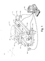
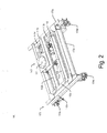
- a wire detection system 100 comprises a frame 110, a test platform 140 coupled to the frame 110 and upon which the object may be mounted.
- the test platform 140 may be rotated relative to the frame 110 about an axis between a first position in which the object is in a first orientation and a second position in which the object is in a second orientation.
- the system 100 further comprises at least three load cells 160 coupled to the frame 110 to collect mass data related to an object positioned on the test platform 140, and a computer-based processing device 180 coupled to the at least three load cells.
- the frame 110 comprises a four crossbars 112a, 112b, 112c, 112d formed from a suitable material such as, e.g. steel, aluminum, or the like.
- Crossbars 112a, 112b, 112c, 112d which may be referred to collectively herein by reference numeral 112, are connected to form a rigid, rectangular structure.
- the crossbars could be formed from other materials in alternate geometric shapes.
- test platform 140 is mounted to the crossbars 114, 116 and is supported on a first end by a hinge assembly 120 and on an opposing end by a hoist 130.
- test platform 140 also comprises four crossbars 142a, 142b, 142c, 142d formed from a suitable material such as, e.g. steel, aluminum, or the like.
- Crossbars 142a, 142b, 142c, 142d which may be referred to collectively herein by reference numeral 142, are connected to form a rigid, rectangular structure.
- the crossbars could be formed from other materials in alternate geometric shapes.
- Test platform 140 further comprises a mounting pad 144 onto which an object may be mounted.
- the mounting pad is a substantially circular structure steel pad mounted on the crossbars 142b, 142c.
- the mounting pad 144 could be formed from other materials in alternate geometric shapes.
- Hoist 130 is mounted between crossbar 112d and crossbar 142d and functions to raise and lower crossbar 142d, thereby rotating platform 140 about the C-axis extending through the hinge assembly 120.
- Hoist 130 may be embodied as a hydraulic hoist, an electric hoist, or the like. In the embodiment depicted herein hoist 130 is coupled to motor 132 which raises and lowers the hoist 130 to rotate platform 140 relative to the frame 110.
- a plurality of load cells 160a, 160b, 160c, 160d which may be referred to collectively by reference numeral 160, are coupled to the frame 110 to collect data from loads positioned on the frame 110.
- load cells are mounted on frame 110.
- Load cells 160a, 160b, 160c are visible in Fig. 1 .
- Load cell 160d is behind platform 140 in the perspective view of Fig. 1 and is therefore not visible.
- Load cells 160 generate an output which is proportional to the force applied to the load cell. Outputs from load cells 160 may be amplified or otherwise processed and input to a computer-based processing device 180.
- the frame 110 may be mounted on a cart 170 such that the entire system 100 is mobile.
- Cart 170 comprises a four crossbars 172a, 172b, 172c, 172d formed from a suitable material such as, e.g. steel, aluminum, or the like.
- Crossbars 172a, 172b, 172c, 172d which may be referred to collectively herein by reference numeral 172, are connected to form a rigid, rectangular structure.
- the crossbars could be formed from other materials in alternate geometric shapes.
- Frame 170 is mounted on wheels 174a, 174b, 174c, 174d, which may be referred to collectively herein by reference numeral 174, and which are adapted to rest upon a ground surface.
- a coordinate system may be mapped onto the three-dimensional space surrounding the platform 140.
- a Cartesian coordinate system may be used to map the space, with the x-axis extending in a direction substantially parallel to the crossbar 112c, the y-axis substantially parallel to the crossbar 112a, and the z-axis substantially perpendicular to the plane defined by the x-axis and the y-axis. It may be preferable for certain applications that the plane defined by the x-axis and the y-axis are parallel or substantially parallel to the ground surface, upon which the platform 140 rests. In other embodiments the origin of the coordinate system may be placed at load cell 160b.
- the particular coordinate system is not critical to the invention and that the space may be mapped using alternate coordinate systems, e.g., polar coordinates, and that the orientation of the coordinate system may be rotated or translated.
- Fig. 5 is a schematic illustration of a computing system 180 which may be adapted to implement center of gravity determination, according to one or more of the embodiments described herein.
- system 180 may include one or more accompanying input/output devices including a display 502 having a screen 504, one or more speakers 506, a keyboard 510, one or more other I/O device(s) 512, and a mouse 514.
- the other I/O device(s) 512 may include a touch screen, a voice-activated input device, a track ball, and any other device that allows the system 180 to receive input from a user.
- the system 180 includes system hardware 520 and memory 530, which may be implemented as random access memory and/or read-only memory.
- a file store 580 may be communicatively coupled to system 180.
- File store 580 may be internal to computing device 508 such as, e.g., one or more hard drives, CD-ROM drives, DVD-ROM drives, or other types of storage devices.
- File store 580 may also be external to computer 508 such as, e.g., one or more external hard drives, network attached storage, or a separate storage network.
- System hardware 520 may include one or more processors 522, at least two graphics processors 524, network interfaces 526, and bus structures 528.
- processor 522 may be embodied as an Intel ® Core2 Duo® processor available from Intel Corporation, Santa Clara, California, USA.
- processor means any type of computational element, such as but not limited to, a microprocessor, a microcontroller, a complex instruction set computing (CISC) microprocessor, a reduced instruction set (RISC) microprocessor, a very long instruction word (VLIW) microprocessor, or any other type of processor or processing circuit.
- CISC complex instruction set computing
- RISC reduced instruction set
- VLIW very long instruction word
- Graphics processors 524 may function as adjunct processors that manage graphics and/or video operations. Graphics processors 524 may be integrated onto the motherboard of computing system 500 or may be coupled via an expansion slot on the motherboard.
- network interface 526 could be a wired interface such as an Ethernet interface (see, e.g., Institute of Electrical and Electronics Engineers/IEEE 802.3-2002) or a wireless interface such as an IEEE 802.11 a, b or g-compliant interface (see, e.g., IEEE Standard for IT-Telecommunications and information exchange between systems LAN/MAN--Part II: Wireless LAN Medium Access Control (MAC) and Physical Layer (PHY) specifications Amendment 4: Further Higher Data Rate Extension in the 2.4 GHz Band, 802.11G-2003).
- GPRS general packet radio service
- Bus structures 528 connect various components of system hardware 128.
- bus structures 528 may be one or more of several types of bus structure(s) including a memory bus, a peripheral bus or external bus, and/or a local bus using any variety of available bus architectures including, but not limited to, 11-bit bus, Industrial Standard Architecture (ISA), Micro-Channel Architecture (MSA), Extended ISA (EISA), Intelligent Drive Electronics (IDE), VESA Local Bus (VLB), Peripheral Component Interconnect (PCI), Universal Serial Bus (USB), Advanced Graphics Port (AGP), Personal Computer Memory Card International Association bus (PCMCIA), and Small Computer Systems Interface (SCSI).
- ISA Industrial Standard Architecture
- MSA Micro-Channel Architecture
- EISA Extended ISA
- IDE Intelligent Drive Electronics
- VLB VESA Local Bus
- PCI Peripheral Component Interconnect
- USB Universal Serial Bus
- AGP Advanced Graphics Port
- PCMCIA Personal Computer Memory Card International Association bus
- SCSI Small Computer Systems Interface
- Memory 530 may include an operating system 540 for managing operations of computing device 508.
- operating system 540 includes a hardware interface module 554 that provides an interface to system hardware 520.
- operating system 540 may include a file system 550 that manages files used in the operation of computing device 508 and a process control subsystem 552 that manages processes executing on computing device 508.
- Operating system 540 may include (or manage) one or more communication interfaces that may operate in conjunction with system hardware 120 to transceive data packets and/or data streams from a remote source. Operating system 540 may further include a system call interface module 542 that provides an interface between the operating system 540 and one or more application modules resident in memory 530. Operating system 540 may be embodied as a UNIX operating system or any derivative thereof (e.g., Linux, Solaris, etc.) or as a Windows® brand operating system, or other operating systems.
- system 180 may be embodied as a personal computer, a laptop computer, a personal digital assistant, a mobile telephone, an entertainment device, or another computing device.
- memory 530 includes one or more logic modules embodied as logic instructions encoded on a tangible, non transitory memory to impart functionality to the system 180.
- the embodiment depicted in Fig. 5 comprises a data collection module 562, and an analysis module 564. Additional details about the process and operations implemented by these modules are described with reference to Figs. 4A-4B , and Fig. 6 below.
- the system 100 may be employed to determine the center of gravity in three-dimensional space of an object mounted on the platform.
- the object may be irregular in shape, volume, density, and distribution of mass.
- an object may be positioned on the platform 140 when the platform 140 is in a first position substantially parallel with the frame.
- the data collection module 562 collects data from the load cells 160 and the analysis module 566 uses the data collected from the load cells 160 to determine the center of gravity along the X-axis and Y-axis.
- the hoist 130 is then activated to rotate the object through a predetermined angular range of motion, thereby shifting the center of gravity of the object along the X-axis.
- the change in the position of the center of gravity along the X-axis may then be used to determine a position of the center of gravity of the object in the Z-axis.
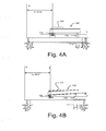
- a calibration process may be implemented to determine the center of gravity of the platform 140 when the platform is in a substantially flat orientation, as depicted in Fig. 4A .
- the system 100 may be activated and the data collection module 562 collects force data from each load cell 160.
- the hoist is then activated to rotate platform 140 through a predetermined angle ⁇ about a C-axis extending through the hinge assembly 120.
- the predetermined angle ⁇ measures between 1 degree and 10 degrees, although angles greater than 10 degrees may be used.
- the angle ⁇ may be determined using an inclinometer or similar instrument.
- the center of gravity of the platform 140 along the X-axis is then calculated using Equation (1) above. This results in a mapping between the predetermined angle of rotation ⁇ and the X-axis center of gravity, X_rig_angle. This mapping may be stored in a memory module.
- a single angle of rotation ⁇ may be used.
- the calibration process may rotate the platform incrementally through a range of predetermined angles ⁇ and may record the X-axis center of gravity, X_rig_angle at each rotation angle ⁇ .
- the values may be stored in a data table or other suitable data structure in memory 530 of system 180, or in the file store 580 coupled to system 180.
- the system 100 may be used to determine the center of gravity of an object mounted on platform 140.
- an object is positioned on the platform when the platform is in a first position.
- the first position corresponds to the platform being positioned substantially parallel to the frame 110, i.e., a rotation angle ⁇ of zero degrees.
- m model represents the mass of the object mounted on the platform 110
- m tot represents the total mass measured by the load cells 160
- m rig represents the mass of the platform 140 measured by the load cells 160 during the calibration process.
- x mzero represents the X-axis center of gravity of the object when the platform is not rotated, i.e., at a rotation angle of zero degrees
- x totzero represents the x-axis center of gravity of the object and the platform when the platform is not rotated, i.e., at a rotation angle of zero degrees
- x rigzero represents the x-axis center of gravity of the platform when the platform is not rotated, i.e., at a rotation angle of zero degrees.
- the object is rotated to a second orientation by activating the hoist assembly to rotate the platform 140 about the C-axis extending through the hinge assembly 120 to the predetermined rotation angle ⁇ at which the platform was calibrated in operation 610.
- x mangle represents the X-axis center of gravity of the object when the platform is rotated at the rotation angle of ⁇ degrees
- x totangle represents the x-axis center of gravity of the object and the platform when the platform is rotated at the rotation angle of ⁇ degrees
- x rigangle represents the x-axis center of gravity of the platform when the platform rotated at the rotation angle of ⁇ degrees.
- the changes in the X-axis center of gravity may be used to determine the center of gravity of the object along a Z-axis, substantially orthogonal to the plane defined by the X-axis and the Y-axis.
- Z cgatttach represents the Z-axis center of gravity of the object measured with reference to an attachment point of the platform
- X 0 represents the X-axis center of gravity of the object when the platform 140 is in the initial position, i.e., disposed at a rotation angle of zero degrees
- X t represents the X-axis center of gravity when the platform 140 is in the second position, i.e., disposed at a rotation angle of ⁇ .
- the attachment point may be displaced from the pivot point defined by the C-axis extending through the hinge assembly 140 by a distance a along the Z-axis.
- Za represents the displacement of attachment point from the pivot point along the Z-axis.
- the model depicted in Fig. 7 calculates the Z-axis center of gravity using a coordinate system positioned at the attachment point. In some embodiments it may be useful to translate the coordinate system to a reference position measured from an edge of the platform, as illustrated in Figs. 3 and 4A-4B. In such a coordinate system the X-axis may be translated by an amount representing the pivot offset along the X-axis, represented by Xp Offset in Figs. 4A and 4B .
- Xm zero_pivot Xm zero - Xp offset
- Xm zero_point represents the X-axis center of gravity in the coordinate system centered about the pivot point
- Xm zero represents the X-axis center of gravity in the coordinate system measured from the edge of the platform
- Xp offset represents the X-axis offset between the two.
- Xm angle_point represents the X-axis center of gravity in the coordinate system centered about the pivot point
- Xm angle represents the X-axis center of gravity in the coordinate system measured from the edge of the platform
- Xp offset represents the X-axis offset between the two.
- the (X,Y,Z) coordinates of the center of gravity of the object may be stored in a memory module such as memory 530 or file store 580 of computing system 180.
- the coordinates may be used in subsequent operations in which in which the object may be mounted on a device such as a pylon used in radar cross-section testing.
- a method is disclosed to determine a center of gravity of a three dimensional object, including positioning the object on a test platform 140 in a first orientation, determining a position of the center of gravity along a first axis and a second axis when the object is in the first orientation, rotating the object with respect to a third axis which is substantially orthogonal to the first axis and the second axis to position the object in a second orientation, determining a position of the center of gravity along at least one of the first axis or the second axis when the object is in the second orientation, and using a change in the position of the center of gravity along the at least one of the first axis or the second axis when the object is in the second orientation to determine a position of the center of gravity along the third axis.
- the method includes wherein positioning the object on a test platform 140 in a first orientation comprises positioning the object on a test platform 140 that is oriented substantially parallel to a ground surface.
- the method includes wherein positioning the object on a test platform 140 in a first orientation comprises positioning the object on a test platform 140 that is oriented an angle with respect to a ground surface.
- determining a position of the center of gravity along a first axis and a second axis when the object is in the first orientation includes receiving inputs from at least three load cells 160 coupled to the test platform 140, and using the inputs from the at least three load cells 160 to determine a position of the center of gravity of the object along an X-axis substantially parallel to the first axis and a Y-axis substantially parallel to the second axis when the object is in the first orientation.
- the method includes wherein rotating the object with respect to a third axis which is substantially orthogonal to the first axis and the second axis comprises rotating the object about a C-axis, substantially parallel to an X-axis substantially parallel to the first axis, through a predetermined angle measuring between two degrees and 15 degrees.
- the method includes wherein using a change in the position of the center of gravity along the at least one of the first axis or the second axis when the object is in the second orientation to determine a position of the center of gravity along the third axis comprises calculating a Z-axis center of gravity measured from a C-axis, substantially parallel to an X-axis, wherein the Z-axis is substantially parallel to the third axis and the X-axis is substantially parallel to the first axis.
- the method further includes implementing a calibration process to determine the center of gravity of the platform in three-dimensional space in the first orientation and the second orientation; and adjusting the position of the center of gravity of the object to compensate for the center of gravity of the platform 140.
- a system to determine a center of gravity of a three dimensional object including a frame 110, a test platform 140 coupled to the frame 110 and upon which the object may be mounted, wherein the test platform 140 is rotatable relative to the frame 110 about first, second, and third axes between a first position in which the object is in a first orientation and a second position in which the object is in a second orientation, wherein the third axis is substantially orthogonal to the first and second axes, at least three load cells 160 coupled to the frame 110 to collect mass data related to an object positioned on the test platform 140, and a computer-based processing device 180 coupled to the at least three load cells 160 and including logic instruction stored in a non-transitory computer readable medium which, when executed by the processing device 180, configures the processing device 180.
- the processing device 180 is configured to receive a first data set from the at least three load cells 160 when the object is positioned on the test platform 140 in the first orientation; determine a position of the center of gravity along the first axis and the second axis when the object is in the first orientation; receive a second data set from the at least three load cells 160 when the object is rotated about the third axis and positioned on the test platform 140 in the second orientation, determine a position of the center of gravity along at least one of the first axis or the second axis when the object is in the second orientation, and use a change in the position of the center of gravity along the at least one of the first axis or the second axis when the object is in the second orientation to determine a position of the center of gravity along the third axis.
- the system includes wherein the first orientation positions the object on the test platform 140 when it is oriented substantially parallel to a ground surface. In yet another instance, the system includes wherein the first orientation positions the object on the test platform 140 when it is oriented an angle with respect to a ground surface.
- the system includes wherein the computer-based processing device 180 further includes logic instruction stored in a non-transitory computer readable medium which, when executed by the processing device 180, configures the processing device 180 to receive inputs from at least three load cells 160 coupled to the test platform 140; and use the inputs from the at least three load cells 160 to determine a position of the center of gravity of the object along an X-axis and a Y-axis when the object is in the first orientation.
- the system includes wherein the object is rotated with respect to a Z-axis through a predetermined angle measuring between two degrees and 15 degrees.
- the computer-based processing device 180 further comprises logic instruction stored in a non-transitory computer readable medium which, when executed by the processing device 180, configures the processing device 180 to calculate a Z-axis center of gravity measured from a C-axis, substantially parallel to an X-axis that is substantially parallel to the first axis.
- the system includes wherein the computer-based processing device 180 further includes logic instruction stored in a non-transitory computer readable medium which, when executed by the processing device 180, configures the processing device 180 to implement a calibration process to determine the center of gravity of the platform in three-dimensional space in the first orientation and the second orientation, and adjust the position of the center of gravity of the object to compensate for the center of gravity of the platform.
- a computer-based system to determine a determine a center of gravity of a three dimensional object, including: a non-transitory memory module, a computer-based processing device 180 coupled to memory, and logic instruction stored in the non-transitory memory module which, when executed by the processing device 180, configures the processing device 180 to receive a first data set from at least three load cells 160 coupled to a test platform 140 holding a the object in a first orientation, determine a position of the center of gravity along a first axis and a second axis in three dimensional space when the object is in the first orientation, receive a second data set from the at least three load cells 160 when the object is rotated about a third axis substantially orthogonal to the first and second axes and positioned on the test platform 140 in a second orientation, different from the first orientation; determine a position of the center of gravity along at least one of the first axis or the second axis when the object is in the second orientation, and use a change in the position of
- the computer-based system includes wherein the first orientation positions the object on the test platform 140 when it is oriented substantially parallel to a ground surface. In yet another example, the computer-based system includes wherein the first orientation positions the object on the test platform 140 when it is oriented an angle with respect to a ground surface.
- the computer-based system further includes logic instruction which, when executed by the processing device 180, configures the processing device 180 to receive inputs from at least three load cells 160 coupled to the test platform 140; and use the inputs from the at least three load cells 160 to determine a position of the center of gravity of the object along an X-axis and a Y-axis when the object is in the first orientation.
- the computer-based system includes wherein the object is rotated with respect to a Z-axis through a predetermined angle measuring between two degrees and 15 degrees.
- the computer-based system further includes logic instruction which, when executed by the processing device 180, configures the processing device 180 to calculate a Z-axis center of gravity measured from a C-axis, substantially parallel to an X-axis that is substantially parallel to the first axis.
- the computer-based system further includes logic instruction which, when executed by the processing device 180, configures the processing device 180 to implement a calibration process to determine the center of gravity of the test platform 140 in three-dimensional space in the first orientation and the second orientation, and adjust the position of the center of gravity of the object to compensate for the center of gravity of the test platform 140.
- a system to determine the center of gravity of an object determines the center of gravity in an X-Y plane when the object is disposed on a platform in a first orientation.
Landscapes
- Engineering & Computer Science (AREA)
- Aviation & Aerospace Engineering (AREA)
- Physics & Mathematics (AREA)
- General Physics & Mathematics (AREA)
- Testing Of Balance (AREA)
- Length Measuring Devices With Unspecified Measuring Means (AREA)
Abstract
Description
- This disclosure relates to testing and evaluation of objects and to systems and methods to determine the center of gravity of an object under testing and evaluation. Various applications may benefit from an ability to determine the center of gravity of an object which may be of an irregular shape, volume, and mass. One exemplary application from the aerospace industry relates to radar cross-section testing, during which objects such as a complete aircraft, models thereof, or components thereof may be mounted on a pylon and positioned in a radar test field. In order to balance the object on the pylon it is useful to position the object such that the object's center of gravity is disposed proximate a longitudinal axis that extends through the pylon. Thus, systems and methods to determine the center of gravity of the test object may find utility.
- In various aspects, systems and methods to determine the center of gravity of a device are provided. In some embodiments, systems and methods as described herein first locate the center of gravity of a test object in two axes when the object is positioned in a first orientation. The object is then rotated with respect to a third axis into a second orientation and the center of gravity is determined in at least one of the two axes. A change in the center of gravity between the first orientation and the second orientation may be used to determine the center of gravity along the third axis. In an exemplary system the first and second axes are X and Y axes, and the third axis is a Z axis.
- Thus, in one embodiment there is provided a method to determine a center of gravity of a three dimensional object comprises positioning the object on a test platform in a first orientation, determining a position of the center of gravity along a first axis and a second axis when the object is in the first orientation, rotating the object with respect to a third axis which is substantially orthogonal to the first axis and the second axis, determining a position of the center of gravity along at least one of the first axis or the second axis when the object is in the second orientation, and using a change in the position of the center of gravity along the at least one of the first axis or the second axis when the object is in the second orientation to determine a position of the center of gravity along the third axis.
- In another embodiment there is provided a system to determine a center of gravity of a three dimensional object, comprising a frame, a test platform coupled to the frame and upon which the object may be mounted. In some embodiments the test platform is rotatable relative to the frame about an axis between a first position in which the object is in a first orientation and a second position in which the object is in a second orientation. The system further comprises at least three load cells coupled to the test platform to collect mass data related to an object positioned on the test platform and a computer-based processing device coupled to the at least three load cells.
- The computer-based processing device comprises logic instruction stored in a non-transitory computer readable medium which, when executed by the processing device, configures the processing device to receive a first data set from the at least three load cells when the object is positioned on the test platform in the first orientation, determine a position of the center of gravity along a first axis and a second axis when the object is in the first orientation, and receive a second data set from the at least three load cells when the object is positioned on the test platform in the second orientation, determine a position of the center of gravity along at least one of the first axis or the second axis when the object is in the second orientation, and use a change in the position of the center of gravity along the at least one of the first axis or the second axis when the object is in the second orientation to determine a position of the center of gravity along the third axis.
- In another embodiment there is provided a computer-based system to determine a center of gravity of a three dimensional object comprising a non-transitory memory module, a computer-based processing device coupled to memory, and logic instruction stored in the non-transitory memory module which, when executed by the processing device, configures the processing device to receive a first data set from at least three load cells coupled to a test platform holding a the object in a first orientation, determine a position of the center of gravity along a first axis and a second axis in three dimensional space when the object is in the first orientation, receive a second data set from the at least three load cells when the object is positioned on the test platform in a second orientation, different from the first orientation, determine a position of the center of gravity along at least one of the first axis or the second axis when the object is in the second orientation, and use a change in the position of the center of gravity along the at least one of the first axis or the second axis when the object is in the second orientation to determine a position of the center of gravity along the third axis.
- The features, functions and advantages discussed herein can be achieved independently in various embodiments described herein or may be combined in yet other embodiments, further details of which can be seen with reference to the following description and drawings.
- The detailed description is described with reference to the accompanying figures.
-
Figs. 1 and2 are schematic, perspective views of a system for center of gravity determination in accordance with some embodiments. -
Fig. 3 is a schematic, top view of a system for center of gravity determination in accordance with some embodiments. -
Fig. 4 is schematic, side view of a system for center of gravity determination in accordance with some embodiments. -
Fig. 5 is a schematic illustration of a computing system in which portions of a system for center of gravity determination may be implemented according to embodiments. -
Fig. 6 is a flowchart illustrating operations in a method of center of gravity determination, according to embodiments. -
Fig. 7 is a schematic illustration of a geometric model for center of gravity determination according to embodiments. - Described herein are exemplary systems and methods for center of gravity determination. In the following description, numerous specific details are set forth to provide a thorough understanding of various embodiments. However, it will be understood by those skilled in the art that the various embodiments may be practiced without the specific details. In other instances, well-known methods, procedures, components, and circuits have not been illustrated or described in detail so as not to obscure the particular embodiments.
-
Figs. 1 and2 are schematic, perspective views of a system for center of gravity determination in accordance with some embodiments, andFig. 3 is a schematic, top view of a system for center of gravity determination in accordance with some embodiments. Referring toFigs. 1-3 , in one embodiment awire detection system 100 comprises aframe 110, atest platform 140 coupled to theframe 110 and upon which the object may be mounted. Thetest platform 140 may be rotated relative to theframe 110 about an axis between a first position in which the object is in a first orientation and a second position in which the object is in a second orientation. Thesystem 100 further comprises at least three load cells 160 coupled to theframe 110 to collect mass data related to an object positioned on thetest platform 140, and a computer-basedprocessing device 180 coupled to the at least three load cells. - In greater detail, in the embodiment depicted in
Figs. 1-3 theframe 110 comprises a fourcrossbars - A
test platform 140 is mounted to the crossbars 114, 116 and is supported on a first end by ahinge assembly 120 and on an opposing end by ahoist 130. In the embodiment described hereintest platform 140 also comprises fourcrossbars -
Test platform 140 further comprises amounting pad 144 onto which an object may be mounted. In the embodiment depicted here the mounting pad is a substantially circular structure steel pad mounted on thecrossbars mounting pad 144 could be formed from other materials in alternate geometric shapes. -
Hoist 130 is mounted betweencrossbar 112d andcrossbar 142d and functions to raise and lowercrossbar 142d, thereby rotatingplatform 140 about the C-axis extending through thehinge assembly 120.Hoist 130 may be embodied as a hydraulic hoist, an electric hoist, or the like. In the embodiment depicted hereinhoist 130 is coupled tomotor 132 which raises and lowers thehoist 130 torotate platform 140 relative to theframe 110. - A plurality of
load cells frame 110 to collect data from loads positioned on theframe 110. In one embodiment four load cells are mounted onframe 110.Load cells Fig. 1 . Load cell 160d is behindplatform 140 in the perspective view ofFig. 1 and is therefore not visible. Load cells 160 generate an output which is proportional to the force applied to the load cell. Outputs from load cells 160 may be amplified or otherwise processed and input to a computer-basedprocessing device 180. - Referring to
Figs. 2-3 , in some embodiments theframe 110 may be mounted on acart 170 such that theentire system 100 is mobile.Cart 170 comprises a fourcrossbars Frame 170 is mounted onwheels - A coordinate system may be mapped onto the three-dimensional space surrounding the
platform 140. In one embodiment a Cartesian coordinate system may be used to map the space, with the x-axis extending in a direction substantially parallel to thecrossbar 112c, the y-axis substantially parallel to thecrossbar 112a, and the z-axis substantially perpendicular to the plane defined by the x-axis and the y-axis. It may be preferable for certain applications that the plane defined by the x-axis and the y-axis are parallel or substantially parallel to the ground surface, upon which theplatform 140 rests. In other embodiments the origin of the coordinate system may be placed atload cell 160b. One skilled in the art will recognize that the particular coordinate system is not critical to the invention and that the space may be mapped using alternate coordinate systems, e.g., polar coordinates, and that the orientation of the coordinate system may be rotated or translated. -
Fig. 5 is a schematic illustration of acomputing system 180 which may be adapted to implement center of gravity determination, according to one or more of the embodiments described herein. Referring toFig. 5 , in one embodiment,system 180 may include one or more accompanying input/output devices including adisplay 502 having ascreen 504, one ormore speakers 506, akeyboard 510, one or more other I/O device(s) 512, and amouse 514. The other I/O device(s) 512 may include a touch screen, a voice-activated input device, a track ball, and any other device that allows thesystem 180 to receive input from a user. - The
system 180 includessystem hardware 520 andmemory 530, which may be implemented as random access memory and/or read-only memory. Afile store 580 may be communicatively coupled tosystem 180.File store 580 may be internal to computing device 508 such as, e.g., one or more hard drives, CD-ROM drives, DVD-ROM drives, or other types of storage devices.File store 580 may also be external to computer 508 such as, e.g., one or more external hard drives, network attached storage, or a separate storage network. -
System hardware 520 may include one ormore processors 522, at least twographics processors 524, network interfaces 526, andbus structures 528. In one embodiment,processor 522 may be embodied as an Intel ® Core2 Duo® processor available from Intel Corporation, Santa Clara, California, USA. As used herein, the term "processor" means any type of computational element, such as but not limited to, a microprocessor, a microcontroller, a complex instruction set computing (CISC) microprocessor, a reduced instruction set (RISC) microprocessor, a very long instruction word (VLIW) microprocessor, or any other type of processor or processing circuit. -
Graphics processors 524 may function as adjunct processors that manage graphics and/or video operations.Graphics processors 524 may be integrated onto the motherboard of computing system 500 or may be coupled via an expansion slot on the motherboard. - In one embodiment,
network interface 526 could be a wired interface such as an Ethernet interface (see, e.g., Institute of Electrical and Electronics Engineers/IEEE 802.3-2002) or a wireless interface such as an IEEE 802.11 a, b or g-compliant interface (see, e.g., IEEE Standard for IT-Telecommunications and information exchange between systems LAN/MAN--Part II: Wireless LAN Medium Access Control (MAC) and Physical Layer (PHY) specifications Amendment 4: Further Higher Data Rate Extension in the 2.4 GHz Band, 802.11G-2003). Another example of a wireless interface would be a general packet radio service (GPRS) interface (see, e.g., Guidelines on GPRS Handset Requirements, Global System for Mobile Communications/GSM Association, Ver. 3.0.1, December 2002). -
Bus structures 528 connect various components of system hardware 128. In one embodiment,bus structures 528 may be one or more of several types of bus structure(s) including a memory bus, a peripheral bus or external bus, and/or a local bus using any variety of available bus architectures including, but not limited to, 11-bit bus, Industrial Standard Architecture (ISA), Micro-Channel Architecture (MSA), Extended ISA (EISA), Intelligent Drive Electronics (IDE), VESA Local Bus (VLB), Peripheral Component Interconnect (PCI), Universal Serial Bus (USB), Advanced Graphics Port (AGP), Personal Computer Memory Card International Association bus (PCMCIA), and Small Computer Systems Interface (SCSI). -
Memory 530 may include anoperating system 540 for managing operations of computing device 508. In one embodiment,operating system 540 includes ahardware interface module 554 that provides an interface tosystem hardware 520. In addition,operating system 540 may include afile system 550 that manages files used in the operation of computing device 508 and aprocess control subsystem 552 that manages processes executing on computing device 508. -
Operating system 540 may include (or manage) one or more communication interfaces that may operate in conjunction withsystem hardware 120 to transceive data packets and/or data streams from a remote source.Operating system 540 may further include a systemcall interface module 542 that provides an interface between theoperating system 540 and one or more application modules resident inmemory 530.Operating system 540 may be embodied as a UNIX operating system or any derivative thereof (e.g., Linux, Solaris, etc.) or as a Windows® brand operating system, or other operating systems. - In various embodiments, the
system 180 may be embodied as a personal computer, a laptop computer, a personal digital assistant, a mobile telephone, an entertainment device, or another computing device. - In one embodiment,
memory 530 includes one or more logic modules embodied as logic instructions encoded on a tangible, non transitory memory to impart functionality to thesystem 180. The embodiment depicted inFig. 5 comprises adata collection module 562, and an analysis module 564. Additional details about the process and operations implemented by these modules are described with reference toFigs. 4A-4B , andFig. 6 below. - In operation, the
system 100 may be employed to determine the center of gravity in three-dimensional space of an object mounted on the platform. The object may be irregular in shape, volume, density, and distribution of mass. In brief overview, in one embodiment an object may be positioned on theplatform 140 when theplatform 140 is in a first position substantially parallel with the frame. Thedata collection module 562 collects data from the load cells 160 and theanalysis module 566 uses the data collected from the load cells 160 to determine the center of gravity along the X-axis and Y-axis. The hoist 130 is then activated to rotate the object through a predetermined angular range of motion, thereby shifting the center of gravity of the object along the X-axis. The change in the position of the center of gravity along the X-axis may then be used to determine a position of the center of gravity of the object in the Z-axis. - In greater detail, and referring to
Fig. 6 , in some embodiments a calibration process may be implemented to determine the center of gravity of theplatform 140 when the platform is in a substantially flat orientation, as depicted inFig. 4A . By way of example, thesystem 100 may be activated and thedata collection module 562 collects force data from each load cell 160. Theanalysis module 562 then calculates the gravitational center of theplatform 140 in the X-axis as follows:
Where L is the distance betweenload cells load cells 160a through 160d. - The following variables are recorded:
- Xp_offset: The distance along the X-axis from the origin to the C-axis extending through the hinge pivot point, 120.
- Zp_offset: The distance along the Z-axis from the origin to the C-axis extending through the hinge pivot point, 120.
- Za: The distance along the Z-axis from the C-axis extending through the hinge pivot point, 120, to the plane of the attachment point, 144.
- M_rig: The total mass of the assembled
structures load cells - X_rig_zero: The center of gravity along the X-axis of the combined
structure - The hoist is then activated to rotate
platform 140 through a predetermined angle θ about a C-axis extending through thehinge assembly 120. In some embodiments the predetermined angle θ measures between 1 degree and 10 degrees, although angles greater than 10 degrees may be used. The angle θ may be determined using an inclinometer or similar instrument. The center of gravity of theplatform 140 along the X-axis is then calculated using Equation (1) above. This results in a mapping between the predetermined angle of rotation θ and the X-axis center of gravity, X_rig_angle. This mapping may be stored in a memory module. - In some embodiments a single angle of rotation θ may be used. In other embodiments the calibration process may rotate the platform incrementally through a range of predetermined angles θ and may record the X-axis center of gravity, X_rig_angle at each rotation angle θ. The values may be stored in a data table or other suitable data structure in
memory 530 ofsystem 180, or in thefile store 580 coupled tosystem 180. - Once the calibration data is stored in memory the
system 100 may be used to determine the center of gravity of an object mounted onplatform 140. Thus, atoperation 615 an object is positioned on the platform when the platform is in a first position. In some embodiments the first position corresponds to the platform being positioned substantially parallel to theframe 110, i.e., a rotation angle θ of zero degrees. The mass of the model is determined by:
- Where mmodel represents the mass of the object mounted on the
platform 110, mtot represents the total mass measured by the load cells 160, and mrig represents the mass of theplatform 140 measured by the load cells 160 during the calibration process. - At
operation 620 the X-axis center of gravity of the object relative to the pivot point defined by the C-axis extending through thehinge assembly 120 may then be calculated using the equation:
- Where xmzero represents the X-axis center of gravity of the object when the platform is not rotated, i.e., at a rotation angle of zero degrees, xtotzero represents the x-axis center of gravity of the object and the platform when the platform is not rotated, i.e., at a rotation angle of zero degrees, and xrigzero represents the x-axis center of gravity of the platform when the platform is not rotated, i.e., at a rotation angle of zero degrees.
- At
operation 625 the object is rotated to a second orientation by activating the hoist assembly to rotate theplatform 140 about the C-axis extending through thehinge assembly 120 to the predetermined rotation angle θ at which the platform was calibrated inoperation 610. - At
operation 630 the center gravity of the object relative to the pivot point may then be calculated using the equation:
- Where xmangle represents the X-axis center of gravity of the object when the platform is rotated at the rotation angle of θ degrees, xtotangle represents the x-axis center of gravity of the object and the platform when the platform is rotated at the rotation angle of θ degrees, and xrigangle represents the x-axis center of gravity of the platform when the platform rotated at the rotation angle of θ degrees.
- At
operation 635 the changes in the X-axis center of gravity may be used to determine the center of gravity of the object along a Z-axis, substantially orthogonal to the plane defined by the X-axis and the Y-axis.Fig. 7 is a schematic illustration of a geometric model for center of gravity determination according to embodiments. Referring toFig. 7 , in some embodiments the center of gravity in the Z-axis may be determined using the equation:
- Where Zcgatttach represents the Z-axis center of gravity of the object measured with reference to an attachment point of the platform, X0 represents the X-axis center of gravity of the object when the
platform 140 is in the initial position, i.e., disposed at a rotation angle of zero degrees, Xt represents the X-axis center of gravity when theplatform 140 is in the second position, i.e., disposed at a rotation angle of θ. In some embodiments the attachment point may be displaced from the pivot point defined by the C-axis extending through thehinge assembly 140 by a distance a along the Z-axis. Thus, the term Za represents the displacement of attachment point from the pivot point along the Z-axis. - The model depicted in
Fig. 7 calculates the Z-axis center of gravity using a coordinate system positioned at the attachment point. In some embodiments it may be useful to translate the coordinate system to a reference position measured from an edge of the platform, as illustrated inFigs. 3 and4A-4B. In such a coordinate system the X-axis may be translated by an amount representing the pivot offset along the X-axis, represented by Xp Offset inFigs. 4A and 4B . - In this coordinate system the X-axis center of gravity of the object oriented in the first position i.e., disposed at a rotation angle of zero degrees may be determined as follows:

- Where Xmzero_point represents the X-axis center of gravity in the coordinate system centered about the pivot point, Xmzero represents the X-axis center of gravity in the coordinate system measured from the edge of the platform, and Xpoffset represents the X-axis offset between the two. Similarly, the X-axis center of gravity of the object oriented in the second position i.e., disposed at a rotation angle of θ degrees may be determined as follows:

- Where Xmangle_point represents the X-axis center of gravity in the coordinate system centered about the pivot point, Xmangle represents the X-axis center of gravity in the coordinate system measured from the edge of the platform, and Xpoffset represents the X-axis offset between the two. In this coordinate system the center of gravity in the Z-axis may be calculated as follows:

- The (X,Y,Z) coordinates of the center of gravity of the object may be stored in a memory module such as
memory 530 orfile store 580 ofcomputing system 180. In some embodiments the coordinates may be used in subsequent operations in which in which the object may be mounted on a device such as a pylon used in radar cross-section testing. - In the text and the figures, a method is disclosed to determine a center of gravity of a three dimensional object, including positioning the object on a
test platform 140 in a first orientation, determining a position of the center of gravity along a first axis and a second axis when the object is in the first orientation, rotating the object with respect to a third axis which is substantially orthogonal to the first axis and the second axis to position the object in a second orientation, determining a position of the center of gravity along at least one of the first axis or the second axis when the object is in the second orientation, and using a change in the position of the center of gravity along the at least one of the first axis or the second axis when the object is in the second orientation to determine a position of the center of gravity along the third axis. In one variant, the method includes wherein positioning the object on atest platform 140 in a first orientation comprises positioning the object on atest platform 140 that is oriented substantially parallel to a ground surface. - In yet another variant, the method includes wherein positioning the object on a
test platform 140 in a first orientation comprises positioning the object on atest platform 140 that is oriented an angle with respect to a ground surface. In still another variant, the method includes wherein determining a position of the center of gravity along a first axis and a second axis when the object is in the first orientation includes receiving inputs from at least three load cells 160 coupled to thetest platform 140, and using the inputs from the at least three load cells 160 to determine a position of the center of gravity of the object along an X-axis substantially parallel to the first axis and a Y-axis substantially parallel to the second axis when the object is in the first orientation. - In another variant, the method includes wherein rotating the object with respect to a third axis which is substantially orthogonal to the first axis and the second axis comprises rotating the object about a C-axis, substantially parallel to an X-axis substantially parallel to the first axis, through a predetermined angle measuring between two degrees and 15 degrees. In yet another variant, the method includes wherein using a change in the position of the center of gravity along the at least one of the first axis or the second axis when the object is in the second orientation to determine a position of the center of gravity along the third axis comprises calculating a Z-axis center of gravity measured from a C-axis, substantially parallel to an X-axis, wherein the Z-axis is substantially parallel to the third axis and the X-axis is substantially parallel to the first axis.
- In another example, the method further includes implementing a calibration process to determine the center of gravity of the platform in three-dimensional space in the first orientation and the second orientation; and adjusting the position of the center of gravity of the object to compensate for the center of gravity of the
platform 140. - In one aspect, a system is disclosed to determine a center of gravity of a three dimensional object including a
frame 110, atest platform 140 coupled to theframe 110 and upon which the object may be mounted, wherein thetest platform 140 is rotatable relative to theframe 110 about first, second, and third axes between a first position in which the object is in a first orientation and a second position in which the object is in a second orientation, wherein the third axis is substantially orthogonal to the first and second axes, at least three load cells 160 coupled to theframe 110 to collect mass data related to an object positioned on thetest platform 140, and a computer-basedprocessing device 180 coupled to the at least three load cells 160 and including logic instruction stored in a non-transitory computer readable medium which, when executed by theprocessing device 180, configures theprocessing device 180. - The
processing device 180 is configured to receive a first data set from the at least three load cells 160 when the object is positioned on thetest platform 140 in the first orientation; determine a position of the center of gravity along the first axis and the second axis when the object is in the first orientation; receive a second data set from the at least three load cells 160 when the object is rotated about the third axis and positioned on thetest platform 140 in the second orientation, determine a position of the center of gravity along at least one of the first axis or the second axis when the object is in the second orientation, and use a change in the position of the center of gravity along the at least one of the first axis or the second axis when the object is in the second orientation to determine a position of the center of gravity along the third axis. In one instance, the system includes wherein the first orientation positions the object on thetest platform 140 when it is oriented substantially parallel to a ground surface. In yet another instance, the system includes wherein the first orientation positions the object on thetest platform 140 when it is oriented an angle with respect to a ground surface. - In yet another instance, the system includes wherein the computer-based
processing device 180 further includes logic instruction stored in a non-transitory computer readable medium which, when executed by theprocessing device 180, configures theprocessing device 180 to receive inputs from at least three load cells 160 coupled to thetest platform 140; and use the inputs from the at least three load cells 160 to determine a position of the center of gravity of the object along an X-axis and a Y-axis when the object is in the first orientation. - In one variant, the system includes wherein the object is rotated with respect to a Z-axis through a predetermined angle measuring between two degrees and 15 degrees. In yet another variant, the system includes wherein the computer-based
processing device 180 further comprises logic instruction stored in a non-transitory computer readable medium which, when executed by theprocessing device 180, configures theprocessing device 180 to calculate a Z-axis center of gravity measured from a C-axis, substantially parallel to an X-axis that is substantially parallel to the first axis. In yet another instance, the system includes wherein the computer-basedprocessing device 180 further includes logic instruction stored in a non-transitory computer readable medium which, when executed by theprocessing device 180, configures theprocessing device 180 to implement a calibration process to determine the center of gravity of the platform in three-dimensional space in the first orientation and the second orientation, and adjust the position of the center of gravity of the object to compensate for the center of gravity of the platform. - In yet another aspect, a computer-based system is disclosed to determine a determine a center of gravity of a three dimensional object, including: a non-transitory memory module, a computer-based
processing device 180 coupled to memory, and logic instruction stored in the non-transitory memory module which, when executed by theprocessing device 180, configures theprocessing device 180 to receive a first data set from at least three load cells 160 coupled to atest platform 140 holding a the object in a first orientation, determine a position of the center of gravity along a first axis and a second axis in three dimensional space when the object is in the first orientation, receive a second data set from the at least three load cells 160 when the object is rotated about a third axis substantially orthogonal to the first and second axes and positioned on thetest platform 140 in a second orientation, different from the first orientation; determine a position of the center of gravity along at least one of the first axis or the second axis when the object is in the second orientation, and use a change in the position of the center of gravity along the at least one of the first axis or the second axis when the object is in the second orientation to determine a position of the center of gravity along the third axis. In yet another instance, the computer-based system includes wherein the first orientation positions the object on thetest platform 140 when it is oriented substantially parallel to a ground surface. In yet another example, the computer-based system includes wherein the first orientation positions the object on thetest platform 140 when it is oriented an angle with respect to a ground surface. - In still another variant, the computer-based system further includes logic instruction which, when executed by the
processing device 180, configures theprocessing device 180 to receive inputs from at least three load cells 160 coupled to thetest platform 140; and use the inputs from the at least three load cells 160 to determine a position of the center of gravity of the object along an X-axis and a Y-axis when the object is in the first orientation. In one variant, the computer-based system includes wherein the object is rotated with respect to a Z-axis through a predetermined angle measuring between two degrees and 15 degrees. In one variant, the computer-based system further includes logic instruction which, when executed by theprocessing device 180, configures theprocessing device 180 to calculate a Z-axis center of gravity measured from a C-axis, substantially parallel to an X-axis that is substantially parallel to the first axis. In yet another variant, the computer-based system further includes logic instruction which, when executed by theprocessing device 180, configures theprocessing device 180 to implement a calibration process to determine the center of gravity of thetest platform 140 in three-dimensional space in the first orientation and the second orientation, and adjust the position of the center of gravity of the object to compensate for the center of gravity of thetest platform 140. - Thus, as described herein a system to determine the center of gravity of an object determines the center of gravity in an X-Y plane when the object is disposed on a platform in a first orientation.
- Reference in the specification to "one embodiment" or "some embodiments" means that a particular feature, structure, or characteristic described in connection with the embodiment is included in at least an implementation. The appearances of the phrase "in one embodiment" in various places in the specification may or may not be all referring to the same embodiment.
- Although embodiments have been described in language specific to structural features and/or methodological acts, it is to be understood that claimed subject matter may not be limited to the specific features or acts described. Rather, the specific features and acts are disclosed as sample forms of implementing the claimed subject matter.
Claims (12)
- A method to determine a center of gravity of a three dimensional object, comprising:positioning the object on a test platform (140) in a first orientation;determining a position of the center of gravity along a first axis and a second axis when the object is in the first orientation;rotating the object with respect to a third axis which is substantially orthogonal to the first axis and the second axis to position the object in a second orientation;determining a position of the center of gravity along at least one of the first axis or the second axis when the object is in the second orientation; andusing a change in the position of the center of gravity along the at least one of the first axis or the second axis when the object is in the second orientation to determine a position of the center of gravity along the third axis.
- The method of claim 1, wherein positioning the object on a test platform (140) in a first orientation comprises positioning the object on a test platform (140) that is oriented substantially parallel to a ground surface.
- The method of claim 1, wherein positioning the object on a test platform (140) in a first orientation comprises positioning the object on a test platform (140) that is oriented an angle with respect to a ground surface.
- The method of any of claims 1-3, wherein determining a position of the center of gravity along a first axis and a second axis when the object is in the first orientation comprises:receiving inputs from at least three load cells (160) coupled to the test platform (140); andusing the inputs from the at least three load cells (160) to determine a position of the center of gravity of the object along an X-axis substantially parallel to the first axis and a Y-axis substantially parallel to the second axis when the object is in the first orientation.
- The method of any of claims 1-4, wherein rotating the object with respect to a third axis which is substantially orthogonal to the first axis and the second axis comprises rotating the object about a C-axis, substantially parallel to an X-axis substantially parallel to the first axis, through a predetermined angle measuring between two degrees and 15 degrees.
- The method of any of claims 1-5, wherein using a change in the position of the center of gravity along the at least one of the first axis or the second axis when the object is in the second orientation to determine a position of the center of gravity along the third axis comprises calculating a Z-axis center of gravity measured from a C-axis, substantially parallel to an X-axis, wherein the Z-axis is substantially parallel to the third axis and the X-axis is substantially parallel to the first axis.
- The method of claim 1, further comprising:implementing a calibration process to determine the center of gravity of the platform in three-dimensional space in the first orientation and the second orientation; andadjusting the position of the center of gravity of the object to compensate for the center of gravity of the platform (140).
- A system to determine a center of gravity of a three dimensional object, comprising:a frame (110);a test platform (140) coupled to the frame (110) and upon which the object may be mounted, wherein the test platform (140) is rotatable relative to the frame (110) about first, second, and third axes between a first position in which the object is in a first orientation and a second position in which the object is in a second orientation, wherein the third axis is substantially orthogonal to the first and second axes;at least three load cells (160) coupled to the frame (110) to collect mass data related to an object positioned on the test platform (140); anda computer-based processing device (180) coupled to the at least three load cells (160) and comprising logic instruction stored in a non-transitory computer readable medium which, when executed by the processing device (180), configures the processing device (180) to:receive a first data set from the at least three load cells (160) when the object is positioned on the test platform (140) in the first orientation;determine a position of the center of gravity along the first axis and the second axis when the object is in the first orientation;receive a second data set from the at least three load cells (160) when the object is rotated about the third axis and positioned on the test platform (140) in the second orientation;determine a position of the center of gravity along at least one of the first axis or the second axis when the object is in the second orientation; anduse a change in the position of the center of gravity along the at least one of the first axis or the second axis when the object is in the second orientation to determine a position of the center of gravity along the third axis; andimplement a calibration process to determine the center of gravity
of the platform in three-dimensional space in the first orientation and the second orientation; andadjust the position of the center of gravity of the object to compensate for the center of gravity of the platform. - The system of claim 8, wherein the first orientation positions the object on the test platform (140) when it is oriented substantially parallel to a ground surface.
- The system of claim 8, wherein the first orientation positions the object on the test platform (140) when it is oriented an angle with respect to a ground surface.
- The system of claim 8, wherein the computer-based processing device (180) further comprises logic instruction stored in a non-transitory computer readable medium which, when executed by the processing device (180), configures the processing device (180) to:receive inputs from at least three load cells (160) coupled to the test platform (140); anduse the inputs from the at least three load cells (160) to determine a position of the center of gravity of the object along an X-axis and a Y-axis when the object is in the first orientation.
- The system of claim 8, wherein the computer-based processing device (180) further comprises logic instruction stored in a non-transitory computer readable medium which, when executed by the processing device (180), configures the processing device (180) to calculate a Z-axis center of gravity measured from a C-axis, substantially parallel to an X-axis that is substantially parallel to the first axis.
Applications Claiming Priority (1)
| Application Number | Priority Date | Filing Date | Title |
|---|---|---|---|
| US13/305,240 US9417151B2 (en) | 2011-11-28 | 2011-11-28 | Center of gravity determination |
Publications (2)
| Publication Number | Publication Date |
|---|---|
| EP2597444A2 true EP2597444A2 (en) | 2013-05-29 |
| EP2597444A3 EP2597444A3 (en) | 2014-03-05 |
Family
ID=47664051
Family Applications (1)
| Application Number | Title | Priority Date | Filing Date |
|---|---|---|---|
| EP12194705.5A Ceased EP2597444A3 (en) | 2011-11-28 | 2012-11-28 | Center of gravity determination |
Country Status (4)
| Country | Link |
|---|---|
| US (1) | US9417151B2 (en) |
| EP (1) | EP2597444A3 (en) |
| JP (1) | JP2013113846A (en) |
| CN (1) | CN103134638B (en) |
Cited By (1)
| Publication number | Priority date | Publication date | Assignee | Title |
|---|---|---|---|---|
| CN113654727A (en) * | 2021-09-10 | 2021-11-16 | 广东博智林机器人有限公司 | Method, system and device for measuring gravity center position, computer device and storage medium |
Families Citing this family (10)
| Publication number | Priority date | Publication date | Assignee | Title |
|---|---|---|---|---|
| TWI585304B (en) * | 2012-06-29 | 2017-06-01 | 鴻準精密工業股份有限公司 | Method for manufacturing fan impeller |
| CN103884471B (en) * | 2014-04-16 | 2016-08-24 | 宁波汇众汽车车桥制造有限公司 | Center of gravity measurement method |
| CN106979843B (en) * | 2016-01-15 | 2019-08-27 | 中国航发常州兰翔机械有限责任公司 | A method for detecting the center of gravity of an aero-engine |
| CN105784276B (en) * | 2016-05-11 | 2017-12-26 | 大连理工大学 | Device for automatic measurement and adjustment of multi-axial inertia of test model of offshore structure and its application method |
| US10309857B2 (en) * | 2016-11-30 | 2019-06-04 | Sikorsky Aircraft Corporation | Systems and methods for determining aircraft center-of-gravity |
| CN107238468B (en) * | 2017-08-01 | 2019-06-18 | 中科新松有限公司 | Method, device, equipment and storage medium for identifying the center of mass of a tool at the end of a robotic arm |
| CN113701945B (en) * | 2021-08-05 | 2024-05-31 | 中冶建筑研究总院有限公司 | A device and method for measuring the center of gravity of a pottery figurine |
| CN114659708B (en) * | 2022-03-17 | 2025-03-18 | 拼多多(上海)网络科技有限公司 | Information processing method, device, equipment and storage medium |
| US12601652B2 (en) * | 2023-04-27 | 2026-04-14 | Viettel Group | Weight and center of gravity measurement equipment for aerial vehicles |
| CN117694841B (en) * | 2024-02-06 | 2024-04-30 | 成都中医药大学 | Gravity center track data acquisition method |
Family Cites Families (27)
| Publication number | Priority date | Publication date | Assignee | Title |
|---|---|---|---|---|
| JPS54145179A (en) * | 1978-05-02 | 1979-11-13 | Kawatetsu Keiryoki Kk | Device for measuring center of gravity of fixed heavy body |
| DE3440571A1 (en) | 1984-11-07 | 1985-11-07 | Daimler-Benz Ag, 7000 Stuttgart | Arrangement for determining the centre of gravity of a test specimen |
| JPH0354432A (en) * | 1989-07-21 | 1991-03-08 | Fujitsu Ltd | Apparatus for measuring weight, center of gravity and moment of inertia of three-dimensional body |
| JPH04328438A (en) * | 1991-04-26 | 1992-11-17 | Mitsubishi Heavy Ind Ltd | Apparatus for measuring weight and center of gravity |
| US5214749A (en) * | 1991-06-12 | 1993-05-25 | Massachusetts Institute Of Technology | Dynamic control of a robot with its center of mass decoupled from an end effector by a redundant linkage |
| JPH06123669A (en) * | 1992-07-23 | 1994-05-06 | Ishikawajima Inspection & Instrumentation Co | Center of gravity measuring device |
| JPH06265433A (en) * | 1993-03-11 | 1994-09-22 | Suzuki Motor Corp | Measuring method of body center of gravity |
| EP0662600A4 (en) * | 1993-06-10 | 1997-02-12 | Oh Yoh Keisoku Kenkyusho Kk | Apparatus for measuring position of moving object. |
| US5387071A (en) * | 1993-06-29 | 1995-02-07 | Pinkston; Donald L. | Rotatable recovery vehicle |
| DE10053605B4 (en) | 2000-10-28 | 2012-08-23 | Robert Bosch Gmbh | System and method for determining the center of gravity of a vehicle |
| EP1419368B1 (en) | 2001-08-24 | 2008-11-12 | United Parcel Service Of America, Inc. | Method and apparatus for measuring and diverting an object from a high-speed conveyor |
| US8322968B1 (en) * | 2004-03-15 | 2012-12-04 | Mizner Richard J | Fork lift for trucks, methods, and associated devices |
| US7415866B2 (en) | 2006-02-14 | 2008-08-26 | Mondher Latiri | Device for determining the center of gravity of an object |
| US7579986B2 (en) | 2006-03-15 | 2009-08-25 | The Boeing Company | Method and system for all-in-view coherent GPS signal PRN codes acquisition and navigation solution determination |
| EP2017172A4 (en) * | 2006-05-09 | 2011-11-02 | Equos Res Co Ltd | VEHICLE, CHARACTERISTIC VALUE ESTIMATING DEVICE AND DEVICE FOR DETERMINING A LOADED ARTICLE |
| US7701393B2 (en) | 2006-12-19 | 2010-04-20 | The Boeing Company | Radio frequency navigation using frequency response matching |
| US7783301B2 (en) | 2006-12-19 | 2010-08-24 | The Boeing Company | Method and device for determining a location of a communications device |
| US20090228210A1 (en) | 2007-06-28 | 2009-09-10 | The Boeing Company | Navigation system based on neutrino detection |
| DE102008038615A1 (en) | 2007-09-18 | 2009-03-19 | Continental Teves Ag & Co. Ohg | Sensor device and method for detecting the movement of a vehicle |
| US7969352B2 (en) | 2008-01-08 | 2011-06-28 | The Boeing Company | Global positioning system accuracy enhancement |
| US7865296B2 (en) | 2008-03-19 | 2011-01-04 | Gm Global Technology Operations, Inc. | Identification of vehicle CG height and mass for roll control |
| US8035558B2 (en) | 2008-05-30 | 2011-10-11 | The Boeing Company | Precise absolute time transfer from a satellite system |
| US7952518B2 (en) | 2008-05-30 | 2011-05-31 | The Boeing Company | Internet hotspots localization using satellite systems |
| CN101487755B (en) | 2009-02-27 | 2011-01-19 | 西安信通控制系统有限责任公司 | Test system and method for drill platform mass centre |
| US8511150B2 (en) | 2009-12-10 | 2013-08-20 | Halliburton Energy Services, Inc. | Methods and systems for determining process variables using location of center of gravity |
| JP2011133297A (en) * | 2009-12-24 | 2011-07-07 | Nippon Sharyo Seizo Kaisha Ltd | Gravity center height measuring apparatus and gravity center height measuring method |
| US8504208B2 (en) * | 2011-05-25 | 2013-08-06 | Honda Motor Co., Ltd. | Mobile object controller and floor surface estimator |
-
2011
- 2011-11-28 US US13/305,240 patent/US9417151B2/en active Active
-
2012
- 2012-10-29 JP JP2012237372A patent/JP2013113846A/en active Pending
- 2012-11-28 CN CN201210495269.2A patent/CN103134638B/en active Active
- 2012-11-28 EP EP12194705.5A patent/EP2597444A3/en not_active Ceased
Non-Patent Citations (1)
| Title |
|---|
| None |
Cited By (1)
| Publication number | Priority date | Publication date | Assignee | Title |
|---|---|---|---|---|
| CN113654727A (en) * | 2021-09-10 | 2021-11-16 | 广东博智林机器人有限公司 | Method, system and device for measuring gravity center position, computer device and storage medium |
Also Published As
| Publication number | Publication date |
|---|---|
| CN103134638A (en) | 2013-06-05 |
| US20130138376A1 (en) | 2013-05-30 |
| EP2597444A3 (en) | 2014-03-05 |
| CN103134638B (en) | 2018-12-14 |
| JP2013113846A (en) | 2013-06-10 |
| US9417151B2 (en) | 2016-08-16 |
Similar Documents
| Publication | Publication Date | Title |
|---|---|---|
| US9417151B2 (en) | Center of gravity determination | |
| RU2445635C2 (en) | Force sensor and method of determining turning radius of moving object | |
| CN106885566A (en) | A kind of method of wearable motion sensor and its anti-magnetic interference | |
| CN202904027U (en) | Autonomous indoor positioning system | |
| CN103941309A (en) | Geomagnetic sensor calibration apparatus and method thereof | |
| CN108318038A (en) | A kind of quaternary number Gaussian particle filtering pose of mobile robot calculation method | |
| Monteiro et al. | Physics experiments using simultaneously more than one smartphone sensors | |
| AU2022405422A1 (en) | Tilt compensation apparatus and tilt compensation method therefor | |
| CN114841965A (en) | Steel structure deformation detection method and device, computer equipment and storage medium | |
| WO2020026514A1 (en) | Indoor position estimation apparatus, indoor position estimation method, and program | |
| CN102914414B (en) | Vibration measuring instrument based on Android platform mobile phone and detection method thereof | |
| CN111415532A (en) | Transportation impact recorder based on Internet of things and recording method thereof | |
| WO2020026513A1 (en) | Indoor position estimation apparatus, user terminal, indoor position estimation method, and program | |
| EP3161499B1 (en) | Magnetometer unit for electronic devices | |
| US9170168B2 (en) | Systems and methods for determining mass properties of vehicle components | |
| CN105303201A (en) | A method and system for handwriting recognition based on motion sensing | |
| CN105628303B (en) | CubeSat centroid measurement method | |
| Akeila et al. | Implementation, calibration and testing of GFINS models based on six-accelerometer cube | |
| Müller et al. | Dynamic multibody model of a turntable ladder truck considering unloaded outriggers and sensitivity-based parameter identification | |
| Cekus et al. | Method of determining the effective surface area of a rigid body under wind disturbances | |
| Sun et al. | Implementing quaternion based AHRS on a MEMS multisensor hardware platform | |
| CN109029427A (en) | Object positioning method, object positioning device and electronic equipment | |
| CN102620891A (en) | Flexible measuring device for center of mass of cabinet and implementation method | |
| CN206847637U (en) | A kind of contactless system for determining object space and posture | |
| CN112098925B (en) | Electronic device, tracking system and tracking method |
Legal Events
| Date | Code | Title | Description |
|---|---|---|---|
| PUAI | Public reference made under article 153(3) epc to a published international application that has entered the european phase |
Free format text: ORIGINAL CODE: 0009012 |
|
| 17P | Request for examination filed |
Effective date: 20121128 |
|
| AK | Designated contracting states |
Kind code of ref document: A2 Designated state(s): AL AT BE BG CH CY CZ DE DK EE ES FI FR GB GR HR HU IE IS IT LI LT LU LV MC MK MT NL NO PL PT RO RS SE SI SK SM TR |
|
| AX | Request for extension of the european patent |
Extension state: BA ME |
|
| PUAL | Search report despatched |
Free format text: ORIGINAL CODE: 0009013 |
|
| AK | Designated contracting states |
Kind code of ref document: A3 Designated state(s): AL AT BE BG CH CY CZ DE DK EE ES FI FR GB GR HR HU IE IS IT LI LT LU LV MC MK MT NL NO PL PT RO RS SE SI SK SM TR |
|
| AX | Request for extension of the european patent |
Extension state: BA ME |
|
| RIC1 | Information provided on ipc code assigned before grant |
Ipc: G01M 1/12 20060101AFI20140128BHEP |
|
| 17Q | First examination report despatched |
Effective date: 20171221 |
|
| STAA | Information on the status of an ep patent application or granted ep patent |
Free format text: STATUS: THE APPLICATION HAS BEEN REFUSED |
|
| 18R | Application refused |
Effective date: 20200311 |