EP2597285A2 - Fuel-air mixture distribution for gas turbine engine combustors - Google Patents
Fuel-air mixture distribution for gas turbine engine combustors Download PDFInfo
- Publication number
- EP2597285A2 EP2597285A2 EP12193572.0A EP12193572A EP2597285A2 EP 2597285 A2 EP2597285 A2 EP 2597285A2 EP 12193572 A EP12193572 A EP 12193572A EP 2597285 A2 EP2597285 A2 EP 2597285A2
- Authority
- EP
- European Patent Office
- Prior art keywords
- fuel
- nozzles
- manifold
- duplex
- recited
- Prior art date
- Legal status (The legal status is an assumption and is not a legal conclusion. Google has not performed a legal analysis and makes no representation as to the accuracy of the status listed.)
- Granted
Links
Images


Classifications
-
- F—MECHANICAL ENGINEERING; LIGHTING; HEATING; WEAPONS; BLASTING
- F02—COMBUSTION ENGINES; HOT-GAS OR COMBUSTION-PRODUCT ENGINE PLANTS
- F02C—GAS-TURBINE PLANTS; AIR INTAKES FOR JET-PROPULSION PLANTS; CONTROLLING FUEL SUPPLY IN AIR-BREATHING JET-PROPULSION PLANTS
- F02C9/00—Controlling gas-turbine plants; Controlling fuel supply in air- breathing jet-propulsion plants
- F02C9/26—Control of fuel supply
- F02C9/28—Regulating systems responsive to plant or ambient parameters, e.g. temperature, pressure, rotor speed
-
- F—MECHANICAL ENGINEERING; LIGHTING; HEATING; WEAPONS; BLASTING
- F02—COMBUSTION ENGINES; HOT-GAS OR COMBUSTION-PRODUCT ENGINE PLANTS
- F02C—GAS-TURBINE PLANTS; AIR INTAKES FOR JET-PROPULSION PLANTS; CONTROLLING FUEL SUPPLY IN AIR-BREATHING JET-PROPULSION PLANTS
- F02C7/00—Features, components parts, details or accessories, not provided for in, or of interest apart form groups F02C1/00 - F02C6/00; Air intakes for jet-propulsion plants
- F02C7/22—Fuel supply systems
- F02C7/228—Dividing fuel between various burners
-
- F—MECHANICAL ENGINEERING; LIGHTING; HEATING; WEAPONS; BLASTING
- F02—COMBUSTION ENGINES; HOT-GAS OR COMBUSTION-PRODUCT ENGINE PLANTS
- F02C—GAS-TURBINE PLANTS; AIR INTAKES FOR JET-PROPULSION PLANTS; CONTROLLING FUEL SUPPLY IN AIR-BREATHING JET-PROPULSION PLANTS
- F02C7/00—Features, components parts, details or accessories, not provided for in, or of interest apart form groups F02C1/00 - F02C6/00; Air intakes for jet-propulsion plants
- F02C7/22—Fuel supply systems
- F02C7/232—Fuel valves; Draining valves or systems
-
- F—MECHANICAL ENGINEERING; LIGHTING; HEATING; WEAPONS; BLASTING
- F23—COMBUSTION APPARATUS; COMBUSTION PROCESSES
- F23R—GENERATING COMBUSTION PRODUCTS OF HIGH PRESSURE OR HIGH VELOCITY, e.g. GAS-TURBINE COMBUSTION CHAMBERS
- F23R3/00—Continuous combustion chambers using liquid or gaseous fuel
- F23R3/28—Continuous combustion chambers using liquid or gaseous fuel characterised by the fuel supply
- F23R3/34—Feeding into different combustion zones
-
- F—MECHANICAL ENGINEERING; LIGHTING; HEATING; WEAPONS; BLASTING
- F05—INDEXING SCHEMES RELATING TO ENGINES OR PUMPS IN VARIOUS SUBCLASSES OF CLASSES F01-F04
- F05D—INDEXING SCHEME FOR ASPECTS RELATING TO NON-POSITIVE-DISPLACEMENT MACHINES OR ENGINES, GAS-TURBINES OR JET-PROPULSION PLANTS
- F05D2260/00—Function
- F05D2260/96—Preventing, counteracting or reducing vibration or noise
- F05D2260/964—Preventing, counteracting or reducing vibration or noise counteracting thermoacoustic noise
-
- F—MECHANICAL ENGINEERING; LIGHTING; HEATING; WEAPONS; BLASTING
- F05—INDEXING SCHEMES RELATING TO ENGINES OR PUMPS IN VARIOUS SUBCLASSES OF CLASSES F01-F04
- F05D—INDEXING SCHEME FOR ASPECTS RELATING TO NON-POSITIVE-DISPLACEMENT MACHINES OR ENGINES, GAS-TURBINES OR JET-PROPULSION PLANTS
- F05D2270/00—Control
- F05D2270/01—Purpose of the control system
- F05D2270/14—Purpose of the control system to control thermoacoustic behaviour in the combustion chambers
Definitions
- the present disclosure relates to a gas turbine engine and, more particularly, to a combustor operations therefor.
- Gas turbine engines such as those which power modem commercial and military aircraft, generally include a compressor for pressurizing an airflow, a combustor for burning a hydrocarbon fuel in the presence of the pressurized air, and a turbine for extracting energy from the resultant combustion gases.
- the combustor generally includes radially spaced inner and outer liners that define an annular combustion chamber therebetween. Arrays of circumferentially distributed combustion air holes penetrate multiple axial locations along each liner to radially admit the pressurized air into the combustion chamber.
- a plurality of circumferentially distributed fuel nozzles project into a forward section of the combustion chamber through a respective fuel nozzle guide to supply the fuel to be mixed with the pressurized air.
- Gas turbine engines are effectively designed for low noise with advanced combustors optimized for low NOx emissions.
- Particular acoustic tones from the combustor may be relative noise contributors since other turbomachinery noise sources have already been significantly reduced.
- a fuel system for a gas turbine engine includes a primary fuel manifold operable to communicate fuel to a primary flow jet in each of a plurality of duplex fuel nozzles and a secondary fuel manifold operable to communicate fuel to a secondary flow jet in each of the duplex fuel nozzles and secondary flow jet in each of a plurality of simplex nozzles.
- An equalizer valve in communication with the primary fuel manifold and the simplex fuel manifold, the equalizer valve movable between an open position and a closed position, the closed position operable to permit supply of the primary fuel manifold with greater fuel pressure than the secondary flow manifold, the open position operable to permit supply of the primary fuel manifold with essentially an equal fuel pressure as the secondary flow manifold.
- a method of noise control from a combustor of a gas turbine engine includes selectively forming a plurality of local circumferential zones with different fuel-air ratios within the combustor.
- FIG. 1 schematically illustrates a gas turbine engine 20.
- the gas turbine engine 20 is disclosed herein as a two-spool turbofan that generally incorporates a fan section 22, a compressor section 24, a combustor section 26 and a turbine section 28.
- Alternative engines might include an augmentor section (not shown) among other systems or features.
- the fan section 22 drives air along a bypass flowpath while the compressor section 24 drives air along a core flowpath for compression and communication into the combustor section 26 then expansion through the turbine section 28.
- FIG. 1 schematically illustrates a gas turbine engine 20.
- the gas turbine engine 20 is disclosed herein as a two-spool turbofan that generally incorporates a fan section 22, a compressor section 24, a combustor section 26 and a turbine section 28.
- Alternative engines might include an augmentor section (not shown) among other systems or features.
- the fan section 22 drives air along a bypass flowpath while the compressor section 24 drives air along a core flowpath for compression and communication into the combustor section 26
- the engine 20 generally includes a low speed spool 30 and a high speed spool 32 mounted for rotation about an engine central longitudinal axis A relative to an engine static structure 36 via several bearing systems 38. It should be understood that various bearing systems 38 at various locations may alternatively or additionally be provided.
- the low speed spool 30 generally includes an inner shaft 40 that interconnects a fan 42, a low pressure compressor 44 and a low pressure turbine 46.
- the inner shaft 40 is connected to the fan 42 through a geared architecture 48 to drive the fan 42 at a lower speed than the low speed spool 30.
- the high speed spool 32 includes an outer shaft 50 that interconnects a high pressure compressor 52 and high pressure turbine 54.
- a combustor 56 is arranged between the high pressure compressor 52 and the high pressure turbine 54.
- the inner shaft 40 and the outer shaft 50 are concentric and rotate about the engine central longitudinal axis A which is collinear with their longitudinal axes.
- the core airflow is compressed by the low pressure compressor 44 then the high pressure compressor 52, mixed and burned with fuel within the combustor 56, then expanded over the high pressure turbine 54 and low pressure turbine 46.
- the turbines 54, 46 rotationally drive the respective low speed spool 30 and high speed spool 32 in response to the expansion.
- the combustor 56 generally includes an outer combustor liner 60 and an inner combustor liner 62.
- the outer combustor liner 60 and the inner combustor liner 62 are spaced inward from a combustor case 64 such that an annular combustion chamber 66 is defined there between. It should be understood that although a particular combustor is illustrated, other combustor types with various liner panel arrangements will also benefit herefrom.
- the outer combustor liner 60 and the combustor case 64 define an outer annular plenum 76 and the inner combustor liner 62 and the combustor case 64 define an inner annular plenum 78.
- the combustor liners 60, 62 contain the flame for direction toward the turbine section 28.
- Each combustor liner 60, 62 generally includes a support shell 68, 70 which supports one or more liner panels 72, 74 mounted to a hot side of the respective support shell 68, 70.
- the liner panels 72, 74 define a liner panel array which may be generally annular in shape.
- Each of the liner panels 72, 74 may be generally rectilinear and manufactured of, for example, a nickel based super alloy or ceramic material.
- the combustor 56 further includes a forward assembly 80 immediately downstream of the compressor section 24 to receive compressed airflow therefrom.
- the forward assembly 80 generally includes an annular hood 82, a bulkhead assembly 84, a multiple of fuel nozzles 86 (one shown) and a multiple of fuel nozzle guides 90 (one shown) that defines a central opening 92.
- the annular hood 82 extends radially between, and is secured to, the forwardmost ends of the liners 60, 62.
- the annular hood 82 includes a multiple of circumferentially distributed hood ports 94 that accommodate the respective fuel nozzle 86 and introduce air into the forward end of the combustion chamber 66.
- Each fuel nozzle 86 may be secured to the outer case 64 and projects through one of the hood ports 94 and through the central opening 92 within the respective fuel nozzle guide 90 along a fuel nozzle axis F.
- the multiple of fuel nozzles 86 (sixteen shown) are arranged in the combustor 56.
- the multiple of fuel nozzles 86 and surrounding structure generate a swirling, intimately blended fuel-air mixture that supports combustion in the forward section of the combustion chamber 66.
- Airflow in the combustor 56 is generally uniform and fuel-air variation in the disclosed non-limiting embodiment is selectively generated by the multiple of fuel nozzles 86.
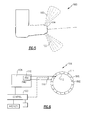
- the variation is selectively generated through a plurality of duplex fuel nozzles 86D (one shown in Figure 4 ) and a plurality of simplex fuel nozzles 86S (one shown in Figure 5 ).
- each of the duplex fuel nozzles 86D include a primary flow jet 100 and secondary flow jets 102.
- the primary flow jet 100 is defined generally along axis F and the secondary flow jets 102 are generally transverse to axis F.
- Each of the simplex fuel nozzles 86S include only the secondary flow jets 102 ( Figure 5 ). It should be appreciated that various jet arrangements may alternatively or additionally be provided.
- a fuel system 106 communicates fuel to the multiple of fuel nozzles 86.
- the fuel system generally includes a fuel metering unit (FMU) 108, a flow divider valve (FDV) 110, a primary fuel manifold 112, a secondary fuel manifold 114, and an equalizing valve 116 which selectively permits fuel communication between the primary fuel manifold 112 and the secondary fuel manifold 114.
- the fuel metering unit (FMU) 108 is a hydromechanical unit that controls fuel flow and the flow divider valve (FDV) 110 proportions the fuel flow to the primary fuel manifold 112 and the secondary fuel manifold 114.
- the primary fuel manifold 112 communicates fuel to the primary flow jet 100 in each of the duplex fuel nozzles 86D and the secondary flow manifold 114 communicates fuel to the secondary flow jets 102 in each of the duplex fuel nozzles 86D and each of the simplex fuel nozzles 86S.
- a module 120 executes a fuel control algorithm 122 ( Figure 7 ).
- the functions of the algorithm 122 are disclosed in terms of functional block diagrams, and it should be understood by those skilled in the art with the benefit of this disclosure that these functions may be enacted in either dedicated hardware circuitry or programmed software routines capable of execution in a microprocessor based electronics control embodiment.
- the module 120 may be a portion of a flight control computer, a portion of a Full Authority Digital Engine Control (FADEC) or other system.
- FADEC Full Authority Digital Engine Control
- the module 120 typically includes a processor, a memory, and an interface.
- the processor may be any type of known microprocessor having desired performance characteristics.
- the memory may, for example only, include computer readable medium which stores the data and control algorithms described herein.
- the interface facilitates communication with the fuel metering unit (FMU) 108, the equalizing valve 116, as well as other avionics and systems.
- FMU fuel metering unit
- the fuel system 106 locates the duplex fuel nozzles 86D adjacent to a set of fuel igniters 124 and opposite the set of fuel igniters 124 ( Figure 3 ). It should be appreciated that the fuel igniters 124 may be located in other circumferential positions and the duplex fuel nozzles 86D would be adjusted in accordance therewith. That is, if the fuel igniters 124 were mounted at bottom dead center (BDC) at positions 8 and 9, for example, the duplex fuel nozzles 86D would be located in positions 7-10 and 15-2.
- BDC bottom dead center
- the duplex fuel nozzles 86D are located in positions 4-7 and 12-15 while positions 7-12 and 15-4 utilize simplex fuel nozzles 86S.
- the equalizing valve 116 is closed such that the primary fuel manifold 112 is provided with greater fuel pressure than the secondary fuel manifold 114 to drive a fuel flow distortion.
- the increased fuel pressure drop (and fuel flow) increases the overall (primary plus secondary) fuel flow to the duplex fuel nozzles 86D in relation to the simplex fuel nozzles 86S. That is, when the equalizing valve 116 is closed, the duplex fuel nozzles 86D generate the relatively high fuel-air ratio mixtures and the simplex fuel nozzles 86S provide the relatively low fuel-air ratio mixtures.
- the varied fuel-air ratio mixtures dampen tangential and axial pressure waves within the combustor 56 to control combustor tones and enhance combustor stability.
- an approximate 50-150 psi difference is provided between the duplex fuel nozzles 86D and the simplex fuel nozzles 86S when the equalizing valve 116 is closed.
- low power as defined herein may include moderate power such as that required for approach conditions and a margin above at least partially into a cruise condition.
- non-low power may include cruise power conditions and above such as a take-off flight condition.
- the equalizing valve 116 allows the selection of fuel asymmetry at low power conditions where combustor tones predominate, and reversion to symmetric operation at high power conditions where uniform fuel-air ratio mixture distribution is desired.
- the local fuel-air mixture ratio control further facilitates enhanced stability for snap transient decelerations. Selective operation of the equalizing valve 116 thereby reduces tone amplitudes over, for example, idle and approach power settings so that community and aircraft cabin noise are minimized yet selectively permits symmetric high power operation during, for example, cruise power settings to enhance downstream turbine durability.
Landscapes
- Engineering & Computer Science (AREA)
- Chemical & Material Sciences (AREA)
- Combustion & Propulsion (AREA)
- Mechanical Engineering (AREA)
- General Engineering & Computer Science (AREA)
- Control Of Turbines (AREA)
Abstract
Description
- The present disclosure relates to a gas turbine engine and, more particularly, to a combustor operations therefor.
- Gas turbine engines, such as those which power modem commercial and military aircraft, generally include a compressor for pressurizing an airflow, a combustor for burning a hydrocarbon fuel in the presence of the pressurized air, and a turbine for extracting energy from the resultant combustion gases. The combustor generally includes radially spaced inner and outer liners that define an annular combustion chamber therebetween. Arrays of circumferentially distributed combustion air holes penetrate multiple axial locations along each liner to radially admit the pressurized air into the combustion chamber. A plurality of circumferentially distributed fuel nozzles project into a forward section of the combustion chamber through a respective fuel nozzle guide to supply the fuel to be mixed with the pressurized air.
- Gas turbine engines are effectively designed for low noise with advanced combustors optimized for low NOx emissions. Particular acoustic tones from the combustor may be relative noise contributors since other turbomachinery noise sources have already been significantly reduced.
- A fuel system for a gas turbine engine according to an exemplary aspect of the present disclosure includes a primary fuel manifold operable to communicate fuel to a primary flow jet in each of a plurality of duplex fuel nozzles and a secondary fuel manifold operable to communicate fuel to a secondary flow jet in each of the duplex fuel nozzles and secondary flow jet in each of a plurality of simplex nozzles. An equalizer valve in communication with the primary fuel manifold and the simplex fuel manifold, the equalizer valve movable between an open position and a closed position, the closed position operable to permit supply of the primary fuel manifold with greater fuel pressure than the secondary flow manifold, the open position operable to permit supply of the primary fuel manifold with essentially an equal fuel pressure as the secondary flow manifold.
- A method of noise control from a combustor of a gas turbine engine according to an exemplary aspect of the present disclosure includes selectively forming a plurality of local circumferential zones with different fuel-air ratios within the combustor.
- Various features will become apparent to those skilled in the art from the following detailed description of the disclosed non-limiting embodiment. The drawings that accompany the detailed description can be briefly described as follows:
-
Figure 1 is a schematic cross-section of a gas turbine engine; -
Figure 2 is a perspective partial sectional view of an exemplary annular combustor that may be used with the gas turbine engine shown inFigure 1 ; -
Figure 3 is a cross sectional schematic view of the exemplary combustor; -
Figure 4 is a perspective view of a duplex fuel nozzle; -
Figure 5 is a perspective view of a simplex fuel nozzle; -
Figure 6 is a schematic view of a fuel system for the exemplary combustor; and -
Figure 7 is a method of operation of the fuel system. -
Figure 1 schematically illustrates agas turbine engine 20. Thegas turbine engine 20 is disclosed herein as a two-spool turbofan that generally incorporates afan section 22, acompressor section 24, acombustor section 26 and aturbine section 28. Alternative engines might include an augmentor section (not shown) among other systems or features. Thefan section 22 drives air along a bypass flowpath while thecompressor section 24 drives air along a core flowpath for compression and communication into thecombustor section 26 then expansion through theturbine section 28. Although depicted as a turbofan gas turbine engine in the disclosed non-limiting embodiment, it should be understood that the concepts described herein are not limited to use with turbofans as the teachings may be applied to other types of turbine engines. - The
engine 20 generally includes alow speed spool 30 and ahigh speed spool 32 mounted for rotation about an engine central longitudinal axis A relative to an enginestatic structure 36 viaseveral bearing systems 38. It should be understood thatvarious bearing systems 38 at various locations may alternatively or additionally be provided. - The
low speed spool 30 generally includes aninner shaft 40 that interconnects afan 42, a low pressure compressor 44 and alow pressure turbine 46. Theinner shaft 40 is connected to thefan 42 through a gearedarchitecture 48 to drive thefan 42 at a lower speed than thelow speed spool 30. Thehigh speed spool 32 includes anouter shaft 50 that interconnects ahigh pressure compressor 52 andhigh pressure turbine 54. Acombustor 56 is arranged between thehigh pressure compressor 52 and thehigh pressure turbine 54. Theinner shaft 40 and theouter shaft 50 are concentric and rotate about the engine central longitudinal axis A which is collinear with their longitudinal axes. - The core airflow is compressed by the low pressure compressor 44 then the
high pressure compressor 52, mixed and burned with fuel within thecombustor 56, then expanded over thehigh pressure turbine 54 andlow pressure turbine 46. Theturbines low speed spool 30 andhigh speed spool 32 in response to the expansion. - With reference to
Figure 2 , thecombustor 56 generally includes anouter combustor liner 60 and aninner combustor liner 62. Theouter combustor liner 60 and theinner combustor liner 62 are spaced inward from acombustor case 64 such that anannular combustion chamber 66 is defined there between. It should be understood that although a particular combustor is illustrated, other combustor types with various liner panel arrangements will also benefit herefrom. - The
outer combustor liner 60 and thecombustor case 64 define an outerannular plenum 76 and theinner combustor liner 62 and thecombustor case 64 define an innerannular plenum 78. Thecombustor liners turbine section 28. Eachcombustor liner support shell more liner panels respective support shell liner panels liner panels - The
combustor 56 further includes aforward assembly 80 immediately downstream of thecompressor section 24 to receive compressed airflow therefrom. Theforward assembly 80 generally includes anannular hood 82, abulkhead assembly 84, a multiple of fuel nozzles 86 (one shown) and a multiple of fuel nozzle guides 90 (one shown) that defines acentral opening 92. Theannular hood 82 extends radially between, and is secured to, the forwardmost ends of theliners annular hood 82 includes a multiple of circumferentiallydistributed hood ports 94 that accommodate therespective fuel nozzle 86 and introduce air into the forward end of thecombustion chamber 66. Eachfuel nozzle 86 may be secured to theouter case 64 and projects through one of thehood ports 94 and through thecentral opening 92 within the respectivefuel nozzle guide 90 along a fuel nozzle axis F. - With reference to
Figure 3 , the multiple of fuel nozzles 86 (sixteen shown) are arranged in thecombustor 56. The multiple offuel nozzles 86 and surrounding structure generate a swirling, intimately blended fuel-air mixture that supports combustion in the forward section of thecombustion chamber 66. - Airflow in the
combustor 56 is generally uniform and fuel-air variation in the disclosed non-limiting embodiment is selectively generated by the multiple offuel nozzles 86. The variation is selectively generated through a plurality ofduplex fuel nozzles 86D (one shown inFigure 4 ) and a plurality ofsimplex fuel nozzles 86S (one shown inFigure 5 ). - With reference to
Figure 4 , each of theduplex fuel nozzles 86D include aprimary flow jet 100 andsecondary flow jets 102. Theprimary flow jet 100 is defined generally along axis F and thesecondary flow jets 102 are generally transverse to axis F. Each of thesimplex fuel nozzles 86S include only the secondary flow jets 102 (Figure 5 ). It should be appreciated that various jet arrangements may alternatively or additionally be provided. - With reference to
Figure 6 , afuel system 106 communicates fuel to the multiple offuel nozzles 86. The fuel system generally includes a fuel metering unit (FMU) 108, a flow divider valve (FDV) 110, aprimary fuel manifold 112, asecondary fuel manifold 114, and an equalizingvalve 116 which selectively permits fuel communication between theprimary fuel manifold 112 and thesecondary fuel manifold 114. The fuel metering unit (FMU) 108 is a hydromechanical unit that controls fuel flow and the flow divider valve (FDV) 110 proportions the fuel flow to theprimary fuel manifold 112 and thesecondary fuel manifold 114. Theprimary fuel manifold 112 communicates fuel to theprimary flow jet 100 in each of theduplex fuel nozzles 86D and thesecondary flow manifold 114 communicates fuel to thesecondary flow jets 102 in each of theduplex fuel nozzles 86D and each of thesimplex fuel nozzles 86S. - A
module 120 executes a fuel control algorithm 122 (Figure 7 ). The functions of thealgorithm 122 are disclosed in terms of functional block diagrams, and it should be understood by those skilled in the art with the benefit of this disclosure that these functions may be enacted in either dedicated hardware circuitry or programmed software routines capable of execution in a microprocessor based electronics control embodiment. In one non-limiting embodiment, themodule 120 may be a portion of a flight control computer, a portion of a Full Authority Digital Engine Control (FADEC) or other system. - The
module 120 typically includes a processor, a memory, and an interface. The processor may be any type of known microprocessor having desired performance characteristics. The memory may, for example only, include computer readable medium which stores the data and control algorithms described herein. The interface facilitates communication with the fuel metering unit (FMU) 108, the equalizingvalve 116, as well as other avionics and systems. - Reduction in tone amplitude has been demonstrated through the formation of local circumferential zones with different fuel-air ratio mixtures. The different fuel-air ratio mixtures in the alternating circumferential zones as defined by the
nozzles Figure 3 ) vary the delay time of heat release, and consequently provide a differential coupling to the associated naturally occurring acoustic frequencies. That is, high-low-high-low local fuel-air ratios are defined about the circumference of thecombustor 56. - The
fuel system 106 locates theduplex fuel nozzles 86D adjacent to a set offuel igniters 124 and opposite the set of fuel igniters 124 (Figure 3 ). It should be appreciated that thefuel igniters 124 may be located in other circumferential positions and theduplex fuel nozzles 86D would be adjusted in accordance therewith. That is, if thefuel igniters 124 were mounted at bottom dead center (BDC) atpositions duplex fuel nozzles 86D would be located in positions 7-10 and 15-2. In the disclosed, non-limiting embodiment of sixteen (16)fuel nozzles 86 where each of thenozzles 86 are separated by 22.5 degrees, theduplex fuel nozzles 86D are located in positions 4-7 and 12-15 while positions 7-12 and 15-4 utilizesimplex fuel nozzles 86S. - At low power conditions, the equalizing
valve 116 is closed such that theprimary fuel manifold 112 is provided with greater fuel pressure than thesecondary fuel manifold 114 to drive a fuel flow distortion. The increased fuel pressure drop (and fuel flow) increases the overall (primary plus secondary) fuel flow to theduplex fuel nozzles 86D in relation to thesimplex fuel nozzles 86S. That is, when the equalizingvalve 116 is closed, theduplex fuel nozzles 86D generate the relatively high fuel-air ratio mixtures and thesimplex fuel nozzles 86S provide the relatively low fuel-air ratio mixtures. The varied fuel-air ratio mixtures dampen tangential and axial pressure waves within thecombustor 56 to control combustor tones and enhance combustor stability. In one example in which theFMU 108 supplies fuel at approximately 100 psi at a low power condition and approximately 1200 psi at a high power condition, an approximate 50-150 psi difference is provided between theduplex fuel nozzles 86D and thesimplex fuel nozzles 86S when the equalizingvalve 116 is closed. It should be appreciate that "low power" as defined herein may include moderate power such as that required for approach conditions and a margin above at least partially into a cruise condition. - At non-low power conditions, the equalizing
valve 116 is open such that theprimary fuel manifold 112 and thesecondary flow manifold 114 receive equalized flow such that theduplex fuel nozzles 86D and thesimplex fuel nozzles 86S generate a symmetric uniform fuel-air ratio throughout thecombustor 56. It should be appreciate that "non-low power" as defined herein may include cruise power conditions and above such as a take-off flight condition. - The equalizing
valve 116 allows the selection of fuel asymmetry at low power conditions where combustor tones predominate, and reversion to symmetric operation at high power conditions where uniform fuel-air ratio mixture distribution is desired. The local fuel-air mixture ratio control further facilitates enhanced stability for snap transient decelerations. Selective operation of the equalizingvalve 116 thereby reduces tone amplitudes over, for example, idle and approach power settings so that community and aircraft cabin noise are minimized yet selectively permits symmetric high power operation during, for example, cruise power settings to enhance downstream turbine durability. - It should be understood that relative positional terms such as "forward," "aft," "upper," "lower," "above," "below," and the like are with reference to the normal operational attitude of the vehicle and should not be considered otherwise limiting.
- Although the different non-limiting embodiments have specific illustrated components, the embodiments of this invention are not limited to those particular combinations. It is possible to use some of the components or features from any of the non-limiting embodiments in combination with features or components from any of the other non-limiting embodiments.
- It should be understood that like reference numerals identify corresponding or similar elements throughout the several drawings. It should also be understood that although a particular component arrangement is disclosed in the illustrated embodiment, other arrangements will benefit herefrom.
- Although particular step sequences are shown, described, and claimed, it should be understood that steps may be performed in any order, separated or combined unless otherwise indicated and will still benefit from the present disclosure.
- The foregoing description is exemplary rather than defined by the limitations within. Various non-limiting embodiments are disclosed herein, however, one of ordinary skill in the art would recognize that various modifications and variations in light of the above teachings will fall within the scope of the appended claims. It is therefore to be understood that within the scope of the appended claims, the disclosure may be practiced other than as specifically described. For that reason the appended claims should be studied to determine true scope and content.
Claims (15)
- A fuel system (106) for a gas turbine engine (20) comprising:a plurality of duplex fuel nozzles (86D);a plurality of simplex fuel nozzles (86S);a primary fuel manifold (112) operable to communicate fuel to a primary flow jet (100) in each of said plurality of duplex fuel nozzles (86D);a secondary fuel manifold (114) operable to communicate fuel to a secondary flow jet (102) in each of said plurality of duplex fuel nozzles (86D) and a secondary flow jet (102) in each of said plurality of simplex nozzles (86S); andan equalizer valve (116) in communication with said primary fuel manifold (112) and said secondary fuel manifold (114), said equalizer valve (116) movable between an open position and a closed position, said closed position operable to permit supply of said primary fuel manifold (112) with greater fuel pressure than said secondary flow manifold (114), said open position operable to permit supply of said primary fuel manifold (112) with essentially an equal fuel pressure as said secondary flow manifold (114).
- The fuel system (106) as recited in claim 1, wherein said plurality of duplex fuel nozzles (86D) are arranged with respect to a fuel igniter (124).
- The fuel system (106) as recited in claim 1 or 2, wherein at least one of said plurality of duplex fuel nozzles (86D) is arranged adjacent to a fuel igniter (124).
- The fuel system (106) as recited in claim 2 or 3, wherein at least one of said plurality of duplex fuel nozzles (86D) is arranged opposite said fuel igniter (124).
- The fuel system (106) as recited in any preceding claim, wherein said primary flow jet (100) in each of said plurality of duplex fuel nozzles (86D) is surrounded by said secondary flow jet (102).
- The fuel system (106) as recited in any preceding claim, wherein said plurality of duplex fuel nozzles (86D) alternate with said plurality of simplex fuel nozzles (86S).
- A method of noise control from a combustor (56) of a gas turbine engine (20) comprising selectively forming a plurality of local circumferential zones with different fuel-air ratios within the combustor (56).
- The method as recited in claim 7, further comprising alternating the local circumferential zones with varied fuel-air ratios, and optionally forming the local circumferential zones as a high-low-high-low local fuel-air ratios.
- The method as recited in claim 7 or 8, further comprising locating at least one of a plurality of duplex fuel nozzles adjacent to a fuel igniter to form at least one high local fuel-air ratio within at least one of the plurality of circumferential zones, and optionally locating at least one of the plurality of duplex fuel nozzles opposite the fuel igniter to form at least one high local fuel-air ratio within at least one of the plurality of circumferential zones.
- The method as recited in any of claims 7 to 9, further comprising alternating a plurality of duplex fuel nozzles (86D) and a plurality of simplex fuel nozzles (86S) to define the plurality of circumferential zones.
- The method as recited in claim 10, further comprising selectively equalizing or dividing a fuel pressure between a primary fuel manifold (112) and a secondary fuel manifold (114), the primary fuel manifold (112) in communication with a primary flow jet (100) in each of the plurality of duplex fuel nozzles (86D) and the secondary fuel manifold (114) in communication with a secondary flow jet (102) in each of the plurality of duplex fuel nozzles (86D) and a secondary flow jet (102) in each of the plurality of simplex nozzles (86S).
- The method as recited in claim 11, further comprising:selectively opening a valve (116) between the primary fuel manifold (112) and the secondary fuel manifold (114); and/orselectively equalizing the fuel pressure in response to a non-low power conditions.
- The method as recited in claim 11 or 12, further comprising selectively dividing the fuel pressure in response to a low power conditions, and optionally wherein the low power condition includes the power required for approach conditions and a margin above at least partially into a cruise condition.
- The method as recited in any of claim 11 to 13, further comprising selectively closing a valve between the primary fuel manifold (112) and the secondary fuel manifold (114).
- The method as recited in any of claims 11 to 14, further comprising selectively forming the plurality of local circumferential zones with varied fuel-air ratios within the combustor (56) in response to a low power condition.
Applications Claiming Priority (1)
| Application Number | Priority Date | Filing Date | Title |
|---|---|---|---|
| US13/301,856 US9631560B2 (en) | 2011-11-22 | 2011-11-22 | Fuel-air mixture distribution for gas turbine engine combustors |
Publications (3)
| Publication Number | Publication Date |
|---|---|
| EP2597285A2 true EP2597285A2 (en) | 2013-05-29 |
| EP2597285A3 EP2597285A3 (en) | 2016-09-07 |
| EP2597285B1 EP2597285B1 (en) | 2019-04-17 |
Family
ID=47278164
Family Applications (1)
| Application Number | Title | Priority Date | Filing Date |
|---|---|---|---|
| EP12193572.0A Active EP2597285B1 (en) | 2011-11-22 | 2012-11-21 | Fuel-air mixture distribution for gas turbine engine combustors |
Country Status (2)
| Country | Link |
|---|---|
| US (1) | US9631560B2 (en) |
| EP (1) | EP2597285B1 (en) |
Cited By (9)
| Publication number | Priority date | Publication date | Assignee | Title |
|---|---|---|---|---|
| EP3255346A1 (en) * | 2016-06-09 | 2017-12-13 | United Technologies Corporation | Reducing noise from a combustor of a gas turbine engine |
| EP3447388A1 (en) * | 2017-08-21 | 2019-02-27 | General Electric Company | Combustion system and method for attenuation of combustion dynamics in a gas turbine engine |
| EP3770403A1 (en) * | 2019-07-22 | 2021-01-27 | Hamilton Sundstrand Corporation | Fuel systems |
| EP4328435A1 (en) * | 2022-08-26 | 2024-02-28 | Hamilton Sundstrand Corporation | Proportional force modification of passive spool for control of secondary nozzle circuits |
| EP4332361A1 (en) * | 2022-08-26 | 2024-03-06 | Hamilton Sundstrand Corporation | Proportional force modification of passive spool for control of simplex circuit of fuel nozzles |
| FR3144205A1 (en) * | 2022-12-21 | 2024-06-28 | Rolls-Royce Plc | Gas turbine fuel delivery |
| EP4394169A1 (en) * | 2022-12-21 | 2024-07-03 | Rolls-Royce plc | Aircraft fuel system |
| US12134985B2 (en) | 2022-08-26 | 2024-11-05 | Collins Engine Nozzles, Inc. | Force modification of passive spool for control of secondary nozzle circuits |
| US12270343B2 (en) | 2022-08-26 | 2025-04-08 | Collins Engine Nozzles, Inc. | Proportional restriction of fuel nozzle with an auxiliary circuit |
Families Citing this family (18)
| Publication number | Priority date | Publication date | Assignee | Title |
|---|---|---|---|---|
| US20140061327A1 (en) * | 2012-08-31 | 2014-03-06 | General Electric Company | System and method for staging fuel to a combustor |
| US9353691B2 (en) * | 2012-12-18 | 2016-05-31 | General Electric Company | Fuel routing system of a gas turbine engine and method of routing fuel |
| US9605598B2 (en) * | 2014-10-17 | 2017-03-28 | United Technologies Corporation | Fuel system for tone control and operability |
| US10738704B2 (en) * | 2016-10-03 | 2020-08-11 | Raytheon Technologies Corporation | Pilot/main fuel shifting in an axial staged combustor for a gas turbine engine |
| US10508811B2 (en) * | 2016-10-03 | 2019-12-17 | United Technologies Corporation | Circumferential fuel shifting and biasing in an axial staged combustor for a gas turbine engine |
| US10393030B2 (en) * | 2016-10-03 | 2019-08-27 | United Technologies Corporation | Pilot injector fuel shifting in an axial staged combustor for a gas turbine engine |
| US10739003B2 (en) * | 2016-10-03 | 2020-08-11 | United Technologies Corporation | Radial fuel shifting and biasing in an axial staged combustor for a gas turbine engine |
| US12241416B2 (en) * | 2022-07-04 | 2025-03-04 | Pratt & Whitney Canada Corp. | Adaptor for a fuel system of an aircraft engine |
| US12454915B2 (en) * | 2022-08-26 | 2025-10-28 | Hamilton Sundstrand Corporation | Force modification of passive valve spools for control of nozzles |
| GB202219423D0 (en) | 2022-12-21 | 2023-02-01 | Rolls Royce Plc | Staged combustor |
| GB202219420D0 (en) * | 2022-12-21 | 2023-02-01 | Rolls Royce Plc | Combustor re-light procedure |
| GB202219384D0 (en) | 2022-12-21 | 2023-02-01 | Rolls Royce Plc | Aircraft fuelling |
| EP4603689A1 (en) * | 2024-02-19 | 2025-08-20 | Rolls-Royce plc | Aircraft comprising a gas turbine engine having primary and secondary fuel-injectors |
| GB202408243D0 (en) | 2024-06-10 | 2024-07-24 | Rolls Royce Plc | Available thrust |
| GB202408242D0 (en) * | 2024-06-10 | 2024-07-24 | Rolls Royce Plc | Aviation fuel |
| GB202408240D0 (en) | 2024-06-10 | 2024-07-24 | Rolls Royce Plc | A gas turbine engine |
| GB202408238D0 (en) * | 2024-06-10 | 2024-07-24 | Rolls Royce Plc | Engine core size |
| GB202408247D0 (en) * | 2024-06-10 | 2024-07-24 | Rolls Royce Plc | lean burn combustor |
Family Cites Families (24)
| Publication number | Priority date | Publication date | Assignee | Title |
|---|---|---|---|---|
| US4967562A (en) * | 1988-12-12 | 1990-11-06 | Sundstrand Corporation | Turbine engine with high efficiency fuel atomization |
| US5345757A (en) | 1993-09-20 | 1994-09-13 | General Electric Company | Combustor apparatus for use in a gas turbine engine |
| US5402634A (en) * | 1993-10-22 | 1995-04-04 | United Technologies Corporation | Fuel supply system for a staged combustor |
| US5848525A (en) | 1996-08-30 | 1998-12-15 | General Electric Company | Fuel manifold staging valve |
| EP0976982B1 (en) * | 1998-07-27 | 2003-12-03 | ALSTOM (Switzerland) Ltd | Method of operating the combustion chamber of a liquid-fuel gas turbine |
| US6666029B2 (en) | 2001-12-06 | 2003-12-23 | Siemens Westinghouse Power Corporation | Gas turbine pilot burner and method |
| DE10160997A1 (en) * | 2001-12-12 | 2003-07-03 | Rolls Royce Deutschland | Lean premix burner for a gas turbine and method for operating a lean premix burner |
| US6915638B2 (en) * | 2002-03-28 | 2005-07-12 | Parker-Hannifin Corporation | Nozzle with fluted tube |
| US6786049B2 (en) | 2002-05-22 | 2004-09-07 | Hamilton Sundstrand | Fuel supply control for a gas turbine including multiple solenoid valves |
| US6962055B2 (en) * | 2002-09-27 | 2005-11-08 | United Technologies Corporation | Multi-point staging strategy for low emission and stable combustion |
| US6968699B2 (en) * | 2003-05-08 | 2005-11-29 | General Electric Company | Sector staging combustor |
| DE102004015187A1 (en) | 2004-03-29 | 2005-10-20 | Alstom Technology Ltd Baden | Combustion chamber for a gas turbine and associated operating method |
| CN1938549B (en) | 2004-03-31 | 2010-09-29 | 阿尔斯通技术有限公司 | Multi-stage burner arrangement for operating a combustion chamber and method for operating the multi-stage burner arrangement |
| US8348180B2 (en) * | 2004-06-09 | 2013-01-08 | Delavan Inc | Conical swirler for fuel injectors and combustor domes and methods of manufacturing the same |
| DE102004036911A1 (en) | 2004-07-29 | 2006-03-23 | Alstom Technology Ltd | Operating procedure for a combustion plant |
| US7540141B2 (en) | 2005-12-13 | 2009-06-02 | Hamilton Sundstrand Corporation | Smart fuel control system |
| US8037688B2 (en) | 2006-09-26 | 2011-10-18 | United Technologies Corporation | Method for control of thermoacoustic instabilities in a combustor |
| EP1930569A1 (en) | 2006-11-01 | 2008-06-11 | ALSTOM Technology Ltd | System for controlling a combustion process for a gas turbine |
| US7841184B2 (en) * | 2007-04-19 | 2010-11-30 | Pratt & Whitney Canada Corp. | Start flow measurement |
| US7966995B2 (en) | 2007-09-05 | 2011-06-28 | Honeywell International Inc. | Dual level pressurization control based on fuel flow to one or more gas turbine engine secondary fuel loads |
| US20090077973A1 (en) | 2007-09-20 | 2009-03-26 | Hamilton Sundstrand Corporation | Gas Turbine Fuel System for High Altitude Starting and Operation |
| US8122725B2 (en) * | 2007-11-01 | 2012-02-28 | General Electric Company | Methods and systems for operating gas turbine engines |
| US8316630B2 (en) | 2008-08-27 | 2012-11-27 | Honeywell International Inc. | Flow equalizing override assembly for fuel divider system |
| US8820087B2 (en) | 2008-09-08 | 2014-09-02 | Siemens Energy, Inc. | Method and system for controlling fuel to a dual stage nozzle |
-
2011
- 2011-11-22 US US13/301,856 patent/US9631560B2/en active Active
-
2012
- 2012-11-21 EP EP12193572.0A patent/EP2597285B1/en active Active
Non-Patent Citations (1)
| Title |
|---|
| None |
Cited By (17)
| Publication number | Priority date | Publication date | Assignee | Title |
|---|---|---|---|---|
| US12359814B2 (en) | 2016-06-09 | 2025-07-15 | Rtx Corporation | Reducing noise from a combustor of a gas turbine engine |
| US11598527B2 (en) | 2016-06-09 | 2023-03-07 | Raytheon Technologies Corporation | Reducing noise from a combustor of a gas turbine engine |
| EP3255346A1 (en) * | 2016-06-09 | 2017-12-13 | United Technologies Corporation | Reducing noise from a combustor of a gas turbine engine |
| EP3447388A1 (en) * | 2017-08-21 | 2019-02-27 | General Electric Company | Combustion system and method for attenuation of combustion dynamics in a gas turbine engine |
| US11181274B2 (en) | 2017-08-21 | 2021-11-23 | General Electric Company | Combustion system and method for attenuation of combustion dynamics in a gas turbine engine |
| US12571540B2 (en) | 2017-08-21 | 2026-03-10 | General Electric Company | Combustion system and method for attenuation of combustion dynamics in a gas turbine engine |
| EP4579131A3 (en) * | 2017-08-21 | 2025-08-20 | General Electric Company | Combustion system and method for attenuation of combustion dynamics in a gas turbine engine |
| EP3770403A1 (en) * | 2019-07-22 | 2021-01-27 | Hamilton Sundstrand Corporation | Fuel systems |
| US11408347B2 (en) | 2019-07-22 | 2022-08-09 | Hamilton Sundstrand Corporation | Fuel systems |
| US11879393B2 (en) | 2019-07-22 | 2024-01-23 | Hamilton Sundstrand Corporation | Fuel systems |
| EP4332361A1 (en) * | 2022-08-26 | 2024-03-06 | Hamilton Sundstrand Corporation | Proportional force modification of passive spool for control of simplex circuit of fuel nozzles |
| US12134985B2 (en) | 2022-08-26 | 2024-11-05 | Collins Engine Nozzles, Inc. | Force modification of passive spool for control of secondary nozzle circuits |
| US12270343B2 (en) | 2022-08-26 | 2025-04-08 | Collins Engine Nozzles, Inc. | Proportional restriction of fuel nozzle with an auxiliary circuit |
| US12313004B2 (en) | 2022-08-26 | 2025-05-27 | Collins Engine Nozzles, Inc. | Proportional force modification of passive spool for control of secondary nozzle circuits |
| EP4328435A1 (en) * | 2022-08-26 | 2024-02-28 | Hamilton Sundstrand Corporation | Proportional force modification of passive spool for control of secondary nozzle circuits |
| EP4394169A1 (en) * | 2022-12-21 | 2024-07-03 | Rolls-Royce plc | Aircraft fuel system |
| FR3144205A1 (en) * | 2022-12-21 | 2024-06-28 | Rolls-Royce Plc | Gas turbine fuel delivery |
Also Published As
| Publication number | Publication date |
|---|---|
| EP2597285A3 (en) | 2016-09-07 |
| EP2597285B1 (en) | 2019-04-17 |
| US9631560B2 (en) | 2017-04-25 |
| US20130125556A1 (en) | 2013-05-23 |
Similar Documents
| Publication | Publication Date | Title |
|---|---|---|
| EP2597285B1 (en) | Fuel-air mixture distribution for gas turbine engine combustors | |
| US10844790B2 (en) | Fuel distribution within a gas turbine engine combustor | |
| EP3301361B1 (en) | Pilot/main fuel shifting in an axial stage combustor for a gas turbine engine | |
| EP3467385B1 (en) | Method of operating a combustion system with main and pilot fuel circuits | |
| EP3008391B1 (en) | Combustor with axial staging for a gas turbine engine | |
| US10107497B2 (en) | Gas turbine engine combustor liner | |
| EP3282190B1 (en) | Combustor | |
| US12359814B2 (en) | Reducing noise from a combustor of a gas turbine engine | |
| EP2895796B1 (en) | Light weight swirler for gas turbine engine combustor and a method of manufacturing | |
| EP3404331A1 (en) | Fuel air mixer assembly for a gas turbine engine combustor | |
| EP2900976A2 (en) | Gas turbine engine asymmetric fuel nozzle combustor | |
| WO2014052221A1 (en) | Fuel distribution within a gas turbine engine combustor | |
| US10533502B2 (en) | Combustor fuel manifold | |
| US11226102B2 (en) | Fuel nozzle for a gas turbine engine | |
| US11885498B2 (en) | Turbine engine with fuel system including a catalytic reformer | |
| EP4411232A1 (en) | High shear fuel distributor | |
| US20160010866A1 (en) | Aerating fuel injector system for a gas turbine engine |
Legal Events
| Date | Code | Title | Description |
|---|---|---|---|
| PUAI | Public reference made under article 153(3) epc to a published international application that has entered the european phase |
Free format text: ORIGINAL CODE: 0009012 |
|
| AK | Designated contracting states |
Kind code of ref document: A2 Designated state(s): AL AT BE BG CH CY CZ DE DK EE ES FI FR GB GR HR HU IE IS IT LI LT LU LV MC MK MT NL NO PL PT RO RS SE SI SK SM TR |
|
| AX | Request for extension of the european patent |
Extension state: BA ME |
|
| PUAL | Search report despatched |
Free format text: ORIGINAL CODE: 0009013 |
|
| AK | Designated contracting states |
Kind code of ref document: A3 Designated state(s): AL AT BE BG CH CY CZ DE DK EE ES FI FR GB GR HR HU IE IS IT LI LT LU LV MC MK MT NL NO PL PT RO RS SE SI SK SM TR |
|
| AX | Request for extension of the european patent |
Extension state: BA ME |
|
| RIC1 | Information provided on ipc code assigned before grant |
Ipc: F02C 7/228 20060101AFI20160804BHEP Ipc: F02C 9/28 20060101ALI20160804BHEP |
|
| RAP1 | Party data changed (applicant data changed or rights of an application transferred) |
Owner name: UNITED TECHNOLOGIES CORPORATION |
|
| STAA | Information on the status of an ep patent application or granted ep patent |
Free format text: STATUS: REQUEST FOR EXAMINATION WAS MADE |
|
| 17P | Request for examination filed |
Effective date: 20170307 |
|
| RBV | Designated contracting states (corrected) |
Designated state(s): AL AT BE BG CH CY CZ DE DK EE ES FI FR GB GR HR HU IE IS IT LI LT LU LV MC MK MT NL NO PL PT RO RS SE SI SK SM TR |
|
| GRAP | Despatch of communication of intention to grant a patent |
Free format text: ORIGINAL CODE: EPIDOSNIGR1 |
|
| STAA | Information on the status of an ep patent application or granted ep patent |
Free format text: STATUS: GRANT OF PATENT IS INTENDED |
|
| INTG | Intention to grant announced |
Effective date: 20181030 |
|
| GRAS | Grant fee paid |
Free format text: ORIGINAL CODE: EPIDOSNIGR3 |
|
| GRAA | (expected) grant |
Free format text: ORIGINAL CODE: 0009210 |
|
| STAA | Information on the status of an ep patent application or granted ep patent |
Free format text: STATUS: THE PATENT HAS BEEN GRANTED |
|
| AK | Designated contracting states |
Kind code of ref document: B1 Designated state(s): AL AT BE BG CH CY CZ DE DK EE ES FI FR GB GR HR HU IE IS IT LI LT LU LV MC MK MT NL NO PL PT RO RS SE SI SK SM TR |
|
| REG | Reference to a national code |
Ref country code: GB Ref legal event code: FG4D |
|
| REG | Reference to a national code |
Ref country code: CH Ref legal event code: EP |
|
| REG | Reference to a national code |
Ref country code: AT Ref legal event code: REF Ref document number: 1121807 Country of ref document: AT Kind code of ref document: T Effective date: 20190515 Ref country code: IE Ref legal event code: FG4D |
|
| REG | Reference to a national code |
Ref country code: DE Ref legal event code: R096 Ref document number: 602012059040 Country of ref document: DE |
|
| REG | Reference to a national code |
Ref country code: NL Ref legal event code: MP Effective date: 20190417 |
|
| REG | Reference to a national code |
Ref country code: LT Ref legal event code: MG4D |
|
| PG25 | Lapsed in a contracting state [announced via postgrant information from national office to epo] |
Ref country code: NL Free format text: LAPSE BECAUSE OF FAILURE TO SUBMIT A TRANSLATION OF THE DESCRIPTION OR TO PAY THE FEE WITHIN THE PRESCRIBED TIME-LIMIT Effective date: 20190417 |
|
| PG25 | Lapsed in a contracting state [announced via postgrant information from national office to epo] |
Ref country code: AL Free format text: LAPSE BECAUSE OF FAILURE TO SUBMIT A TRANSLATION OF THE DESCRIPTION OR TO PAY THE FEE WITHIN THE PRESCRIBED TIME-LIMIT Effective date: 20190417 Ref country code: SE Free format text: LAPSE BECAUSE OF FAILURE TO SUBMIT A TRANSLATION OF THE DESCRIPTION OR TO PAY THE FEE WITHIN THE PRESCRIBED TIME-LIMIT Effective date: 20190417 Ref country code: PT Free format text: LAPSE BECAUSE OF FAILURE TO SUBMIT A TRANSLATION OF THE DESCRIPTION OR TO PAY THE FEE WITHIN THE PRESCRIBED TIME-LIMIT Effective date: 20190817 Ref country code: LT Free format text: LAPSE BECAUSE OF FAILURE TO SUBMIT A TRANSLATION OF THE DESCRIPTION OR TO PAY THE FEE WITHIN THE PRESCRIBED TIME-LIMIT Effective date: 20190417 Ref country code: HR Free format text: LAPSE BECAUSE OF FAILURE TO SUBMIT A TRANSLATION OF THE DESCRIPTION OR TO PAY THE FEE WITHIN THE PRESCRIBED TIME-LIMIT Effective date: 20190417 Ref country code: ES Free format text: LAPSE BECAUSE OF FAILURE TO SUBMIT A TRANSLATION OF THE DESCRIPTION OR TO PAY THE FEE WITHIN THE PRESCRIBED TIME-LIMIT Effective date: 20190417 Ref country code: NO Free format text: LAPSE BECAUSE OF FAILURE TO SUBMIT A TRANSLATION OF THE DESCRIPTION OR TO PAY THE FEE WITHIN THE PRESCRIBED TIME-LIMIT Effective date: 20190717 Ref country code: FI Free format text: LAPSE BECAUSE OF FAILURE TO SUBMIT A TRANSLATION OF THE DESCRIPTION OR TO PAY THE FEE WITHIN THE PRESCRIBED TIME-LIMIT Effective date: 20190417 |
|
| PG25 | Lapsed in a contracting state [announced via postgrant information from national office to epo] |
Ref country code: PL Free format text: LAPSE BECAUSE OF FAILURE TO SUBMIT A TRANSLATION OF THE DESCRIPTION OR TO PAY THE FEE WITHIN THE PRESCRIBED TIME-LIMIT Effective date: 20190417 Ref country code: BG Free format text: LAPSE BECAUSE OF FAILURE TO SUBMIT A TRANSLATION OF THE DESCRIPTION OR TO PAY THE FEE WITHIN THE PRESCRIBED TIME-LIMIT Effective date: 20190717 Ref country code: RS Free format text: LAPSE BECAUSE OF FAILURE TO SUBMIT A TRANSLATION OF THE DESCRIPTION OR TO PAY THE FEE WITHIN THE PRESCRIBED TIME-LIMIT Effective date: 20190417 Ref country code: LV Free format text: LAPSE BECAUSE OF FAILURE TO SUBMIT A TRANSLATION OF THE DESCRIPTION OR TO PAY THE FEE WITHIN THE PRESCRIBED TIME-LIMIT Effective date: 20190417 Ref country code: GR Free format text: LAPSE BECAUSE OF FAILURE TO SUBMIT A TRANSLATION OF THE DESCRIPTION OR TO PAY THE FEE WITHIN THE PRESCRIBED TIME-LIMIT Effective date: 20190718 |
|
| REG | Reference to a national code |
Ref country code: AT Ref legal event code: MK05 Ref document number: 1121807 Country of ref document: AT Kind code of ref document: T Effective date: 20190417 |
|
| PG25 | Lapsed in a contracting state [announced via postgrant information from national office to epo] |
Ref country code: IS Free format text: LAPSE BECAUSE OF FAILURE TO SUBMIT A TRANSLATION OF THE DESCRIPTION OR TO PAY THE FEE WITHIN THE PRESCRIBED TIME-LIMIT Effective date: 20190817 |
|
| REG | Reference to a national code |
Ref country code: DE Ref legal event code: R097 Ref document number: 602012059040 Country of ref document: DE |
|
| PG25 | Lapsed in a contracting state [announced via postgrant information from national office to epo] |
Ref country code: DK Free format text: LAPSE BECAUSE OF FAILURE TO SUBMIT A TRANSLATION OF THE DESCRIPTION OR TO PAY THE FEE WITHIN THE PRESCRIBED TIME-LIMIT Effective date: 20190417 Ref country code: RO Free format text: LAPSE BECAUSE OF FAILURE TO SUBMIT A TRANSLATION OF THE DESCRIPTION OR TO PAY THE FEE WITHIN THE PRESCRIBED TIME-LIMIT Effective date: 20190417 Ref country code: SK Free format text: LAPSE BECAUSE OF FAILURE TO SUBMIT A TRANSLATION OF THE DESCRIPTION OR TO PAY THE FEE WITHIN THE PRESCRIBED TIME-LIMIT Effective date: 20190417 Ref country code: CZ Free format text: LAPSE BECAUSE OF FAILURE TO SUBMIT A TRANSLATION OF THE DESCRIPTION OR TO PAY THE FEE WITHIN THE PRESCRIBED TIME-LIMIT Effective date: 20190417 Ref country code: EE Free format text: LAPSE BECAUSE OF FAILURE TO SUBMIT A TRANSLATION OF THE DESCRIPTION OR TO PAY THE FEE WITHIN THE PRESCRIBED TIME-LIMIT Effective date: 20190417 Ref country code: AT Free format text: LAPSE BECAUSE OF FAILURE TO SUBMIT A TRANSLATION OF THE DESCRIPTION OR TO PAY THE FEE WITHIN THE PRESCRIBED TIME-LIMIT Effective date: 20190417 |
|
| PLBE | No opposition filed within time limit |
Free format text: ORIGINAL CODE: 0009261 |
|
| STAA | Information on the status of an ep patent application or granted ep patent |
Free format text: STATUS: NO OPPOSITION FILED WITHIN TIME LIMIT |
|
| PG25 | Lapsed in a contracting state [announced via postgrant information from national office to epo] |
Ref country code: IT Free format text: LAPSE BECAUSE OF FAILURE TO SUBMIT A TRANSLATION OF THE DESCRIPTION OR TO PAY THE FEE WITHIN THE PRESCRIBED TIME-LIMIT Effective date: 20190417 Ref country code: SM Free format text: LAPSE BECAUSE OF FAILURE TO SUBMIT A TRANSLATION OF THE DESCRIPTION OR TO PAY THE FEE WITHIN THE PRESCRIBED TIME-LIMIT Effective date: 20190417 |
|
| 26N | No opposition filed |
Effective date: 20200120 |
|
| PG25 | Lapsed in a contracting state [announced via postgrant information from national office to epo] |
Ref country code: TR Free format text: LAPSE BECAUSE OF FAILURE TO SUBMIT A TRANSLATION OF THE DESCRIPTION OR TO PAY THE FEE WITHIN THE PRESCRIBED TIME-LIMIT Effective date: 20190417 |
|
| PG25 | Lapsed in a contracting state [announced via postgrant information from national office to epo] |
Ref country code: SI Free format text: LAPSE BECAUSE OF FAILURE TO SUBMIT A TRANSLATION OF THE DESCRIPTION OR TO PAY THE FEE WITHIN THE PRESCRIBED TIME-LIMIT Effective date: 20190417 |
|
| REG | Reference to a national code |
Ref country code: CH Ref legal event code: PL |
|
| PG25 | Lapsed in a contracting state [announced via postgrant information from national office to epo] |
Ref country code: CH Free format text: LAPSE BECAUSE OF NON-PAYMENT OF DUE FEES Effective date: 20191130 Ref country code: MC Free format text: LAPSE BECAUSE OF FAILURE TO SUBMIT A TRANSLATION OF THE DESCRIPTION OR TO PAY THE FEE WITHIN THE PRESCRIBED TIME-LIMIT Effective date: 20190417 Ref country code: LU Free format text: LAPSE BECAUSE OF NON-PAYMENT OF DUE FEES Effective date: 20191121 Ref country code: LI Free format text: LAPSE BECAUSE OF NON-PAYMENT OF DUE FEES Effective date: 20191130 |
|
| REG | Reference to a national code |
Ref country code: BE Ref legal event code: MM Effective date: 20191130 |
|
| PG25 | Lapsed in a contracting state [announced via postgrant information from national office to epo] |
Ref country code: IE Free format text: LAPSE BECAUSE OF NON-PAYMENT OF DUE FEES Effective date: 20191121 |
|
| PG25 | Lapsed in a contracting state [announced via postgrant information from national office to epo] |
Ref country code: BE Free format text: LAPSE BECAUSE OF NON-PAYMENT OF DUE FEES Effective date: 20191130 |
|
| PG25 | Lapsed in a contracting state [announced via postgrant information from national office to epo] |
Ref country code: CY Free format text: LAPSE BECAUSE OF FAILURE TO SUBMIT A TRANSLATION OF THE DESCRIPTION OR TO PAY THE FEE WITHIN THE PRESCRIBED TIME-LIMIT Effective date: 20190417 |
|
| PG25 | Lapsed in a contracting state [announced via postgrant information from national office to epo] |
Ref country code: HU Free format text: LAPSE BECAUSE OF FAILURE TO SUBMIT A TRANSLATION OF THE DESCRIPTION OR TO PAY THE FEE WITHIN THE PRESCRIBED TIME-LIMIT; INVALID AB INITIO Effective date: 20121121 Ref country code: MT Free format text: LAPSE BECAUSE OF FAILURE TO SUBMIT A TRANSLATION OF THE DESCRIPTION OR TO PAY THE FEE WITHIN THE PRESCRIBED TIME-LIMIT Effective date: 20190417 |
|
| PG25 | Lapsed in a contracting state [announced via postgrant information from national office to epo] |
Ref country code: MK Free format text: LAPSE BECAUSE OF FAILURE TO SUBMIT A TRANSLATION OF THE DESCRIPTION OR TO PAY THE FEE WITHIN THE PRESCRIBED TIME-LIMIT Effective date: 20190417 |
|
| REG | Reference to a national code |
Ref country code: DE Ref legal event code: R081 Ref document number: 602012059040 Country of ref document: DE Owner name: RAYTHEON TECHNOLOGIES CORPORATION (N.D.GES.D.S, US Free format text: FORMER OWNER: UNITED TECHNOLOGIES CORPORATION, FARMINGTON, CONN., US Ref country code: DE Ref legal event code: R081 Ref document number: 602012059040 Country of ref document: DE Owner name: RTX CORPORATION (N.D.GES.D. STAATES DELAWARE),, US Free format text: FORMER OWNER: UNITED TECHNOLOGIES CORPORATION, FARMINGTON, CONN., US |
|
| P01 | Opt-out of the competence of the unified patent court (upc) registered |
Effective date: 20230520 |
|
| REG | Reference to a national code |
Ref country code: DE Ref legal event code: R081 Ref document number: 602012059040 Country of ref document: DE Owner name: RTX CORPORATION (N.D.GES.D. STAATES DELAWARE),, US Free format text: FORMER OWNER: RAYTHEON TECHNOLOGIES CORPORATION (N.D.GES.D.STAATES DELAWARE), ARLINGTON, VA, US |
|
| PGFP | Annual fee paid to national office [announced via postgrant information from national office to epo] |
Ref country code: DE Payment date: 20251022 Year of fee payment: 14 |
|
| PGFP | Annual fee paid to national office [announced via postgrant information from national office to epo] |
Ref country code: GB Payment date: 20251023 Year of fee payment: 14 |
|
| PGFP | Annual fee paid to national office [announced via postgrant information from national office to epo] |
Ref country code: FR Payment date: 20251022 Year of fee payment: 14 |