EP2597264A2 - Aerofoil cooling arrangement - Google Patents
Aerofoil cooling arrangement Download PDFInfo
- Publication number
- EP2597264A2 EP2597264A2 EP12193456.6A EP12193456A EP2597264A2 EP 2597264 A2 EP2597264 A2 EP 2597264A2 EP 12193456 A EP12193456 A EP 12193456A EP 2597264 A2 EP2597264 A2 EP 2597264A2
- Authority
- EP
- European Patent Office
- Prior art keywords
- aerofoil
- coolant
- corrugations
- pressure
- peak
- Prior art date
- Legal status (The legal status is an assumption and is not a legal conclusion. Google has not performed a legal analysis and makes no representation as to the accuracy of the status listed.)
- Granted
Links
Images


Classifications
-
- F—MECHANICAL ENGINEERING; LIGHTING; HEATING; WEAPONS; BLASTING
- F01—MACHINES OR ENGINES IN GENERAL; ENGINE PLANTS IN GENERAL; STEAM ENGINES
- F01D—NON-POSITIVE DISPLACEMENT MACHINES OR ENGINES, e.g. STEAM TURBINES
- F01D25/00—Component parts, details, or accessories, not provided for in, or of interest apart from, other groups
- F01D25/08—Cooling; Heating; Heat-insulation
- F01D25/12—Cooling
-
- F—MECHANICAL ENGINEERING; LIGHTING; HEATING; WEAPONS; BLASTING
- F01—MACHINES OR ENGINES IN GENERAL; ENGINE PLANTS IN GENERAL; STEAM ENGINES
- F01D—NON-POSITIVE DISPLACEMENT MACHINES OR ENGINES, e.g. STEAM TURBINES
- F01D5/00—Blades; Blade-carrying members; Heating, heat-insulating, cooling or antivibration means on the blades or the members
- F01D5/12—Blades
- F01D5/14—Form or construction
- F01D5/18—Hollow blades, i.e. blades with cooling or heating channels or cavities; Heating, heat-insulating or cooling means on blades
- F01D5/187—Convection cooling
-
- F—MECHANICAL ENGINEERING; LIGHTING; HEATING; WEAPONS; BLASTING
- F05—INDEXING SCHEMES RELATING TO ENGINES OR PUMPS IN VARIOUS SUBCLASSES OF CLASSES F01-F04
- F05D—INDEXING SCHEME FOR ASPECTS RELATING TO NON-POSITIVE-DISPLACEMENT MACHINES OR ENGINES, GAS-TURBINES OR JET-PROPULSION PLANTS
- F05D2250/00—Geometry
- F05D2250/10—Two-dimensional
- F05D2250/11—Two-dimensional triangular
-
- F—MECHANICAL ENGINEERING; LIGHTING; HEATING; WEAPONS; BLASTING
- F05—INDEXING SCHEMES RELATING TO ENGINES OR PUMPS IN VARIOUS SUBCLASSES OF CLASSES F01-F04
- F05D—INDEXING SCHEME FOR ASPECTS RELATING TO NON-POSITIVE-DISPLACEMENT MACHINES OR ENGINES, GAS-TURBINES OR JET-PROPULSION PLANTS
- F05D2250/00—Geometry
- F05D2250/10—Two-dimensional
- F05D2250/18—Two-dimensional patterned
- F05D2250/184—Two-dimensional patterned sinusoidal
-
- F—MECHANICAL ENGINEERING; LIGHTING; HEATING; WEAPONS; BLASTING
- F05—INDEXING SCHEMES RELATING TO ENGINES OR PUMPS IN VARIOUS SUBCLASSES OF CLASSES F01-F04
- F05D—INDEXING SCHEME FOR ASPECTS RELATING TO NON-POSITIVE-DISPLACEMENT MACHINES OR ENGINES, GAS-TURBINES OR JET-PROPULSION PLANTS
- F05D2260/00—Function
- F05D2260/20—Heat transfer, e.g. cooling
- F05D2260/201—Heat transfer, e.g. cooling by impingement of a fluid
-
- F—MECHANICAL ENGINEERING; LIGHTING; HEATING; WEAPONS; BLASTING
- F05—INDEXING SCHEMES RELATING TO ENGINES OR PUMPS IN VARIOUS SUBCLASSES OF CLASSES F01-F04
- F05D—INDEXING SCHEME FOR ASPECTS RELATING TO NON-POSITIVE-DISPLACEMENT MACHINES OR ENGINES, GAS-TURBINES OR JET-PROPULSION PLANTS
- F05D2260/00—Function
- F05D2260/20—Heat transfer, e.g. cooling
- F05D2260/205—Cooling fluid recirculation, i.e. after cooling one or more components is the cooling fluid recovered and used elsewhere for other purposes
-
- Y—GENERAL TAGGING OF NEW TECHNOLOGICAL DEVELOPMENTS; GENERAL TAGGING OF CROSS-SECTIONAL TECHNOLOGIES SPANNING OVER SEVERAL SECTIONS OF THE IPC; TECHNICAL SUBJECTS COVERED BY FORMER USPC CROSS-REFERENCE ART COLLECTIONS [XRACs] AND DIGESTS
- Y02—TECHNOLOGIES OR APPLICATIONS FOR MITIGATION OR ADAPTATION AGAINST CLIMATE CHANGE
- Y02T—CLIMATE CHANGE MITIGATION TECHNOLOGIES RELATED TO TRANSPORTATION
- Y02T50/00—Aeronautics or air transport
- Y02T50/60—Efficient propulsion technologies, e.g. for aircraft
Definitions
- the present invention relates to a cooling arrangement of an aerofoil, such as in a blade or a vane, typically for a turbine stage of a gas turbine engine.
- Impingement cooling systems utilise impingement plates adjacent an external wall and have an array of small holes through which coolant flows to strike the inner surface of the external wall. Impingement plates may be either separate plate inserted to the aerofoil or integrally cast.
- US7,600,973B discloses a conventional 'multi-pass' cooling system where coolant passes both radially inwardly and outwardly through main cooling passages.
- This design uses film cooling, internal turbulators and impingement cooling to cool its suction side aerofoil wall.
- coolant films over the suction side wall's external surface are penalizing on performance but they are necessary to make up for relatively inefficient internal cooling.
- a first aspect of the present invention provides an aerofoil for a gas turbine engine, the aerofoil comprises a pressure wall and a suction wall, at least one of the pressure and suction walls comprise corrugations and a coolant hole on an inner surface, the corrugations define a downstream surface and the coolant hole having an inlet defined in the downstream surface.
- the corrugations may define an upstream surface.
- the wall may define a passage therein and the coolant hole connects between the inlet and the passage.
- a coolant may flow through the aerofoil and the downstream surface may be angled between 20° and 90° relative to the direction of coolant flow.
- a coolant may flow through the aerofoil and the downstream surface may be angled a is approximately 45° relative to the direction of coolant flow
- a coolant may flow through the aerofoil and the upstream surface may be angled ⁇ between 20° and 70° relative to the direction of coolant flow.
- a coolant may flow through the aerofoil and the upstream surface may be angled ⁇ is approximately 45° relative to the direction of coolant flow
- the corrugations may define any one or more the sectional profiles generally sinusoidal, rounded triangular, trapezoidal or saw-toothed.
- the corrugations define a peak and a cross-section of the passage may have an apex which is adjacent the peak.
- the corrugations may define an amplitude or height approximately 0.7mm.
- the corrugations may define an amplitude or height between 0.5mm and 1.5mm.
- the corrugations may define a peak to peak distance approximately 3mm.
- the corrugations may define a peak to peak distance between peaks between 2.5mm and 5mm.
- a ducted fan gas turbine engine generally indicated at 10 has a principal and rotational axis X-X.
- the terms radial, axial and circumferential are used with respect to this axis.
- the engine comprises, in axial flow series, an air intake 11, a propulsive fan 12, an intermediate pressure compressor 13, a high-pressure compressor 14, combustion equipment 15, a high-pressure turbine 16, an intermediate-pressure turbine 17, a low-pressure turbine 18 and a core engine exhaust nozzle 19.
- a nacelle 21 generally surrounds the engine 10 and defines the intake 11, a bypass duct 22 and a bypass exhaust nozzle 23.
- the gas turbine engine 10 works in a conventional manner so that air entering the intake 11 is accelerated by the fan 12 to produce two air flows: a first air flow A into the intermediate pressure compressor 14 and a second air flow B which passes through the bypass duct 22 to provide propulsive thrust.
- the intermediate pressure compressor 13 compresses the air flow A directed into it before delivering that air to the high pressure compressor 14 where further compression takes place.
- the compressed air exhausted from the high-pressure compressor 14 is directed into the combustion equipment 15 where it is mixed with fuel and the mixture combusted.
- the resultant hot combustion products then expand through, and thereby drive the high, intermediate and low-pressure turbines 16, 17, 18 before being exhausted through the nozzle 19 to provide additional propulsive thrust.
- the high, intermediate and low-pressure turbines respectively drive the high and intermediate pressure compressors 14, 13 and the fan 12 by suitable interconnecting shafts.
- FIG 2 shows an isometric view of a typical single stage cooled turbine.
- the high-pressure turbine 16 is shown.
- the high-pressure turbine 16 comprises an annular array of radially extending stator vanes 31 and immediately downstream an annular array of radially extending blades 32 mounted to a rotor disc 26.
- the combustion gases impinge on the vanes which present the gases at an appropriate angle to efficiently drive the turbine blades.
- stator vanes 31 is immediately downstream of the combustor 15.
- the vanes therefore require significant cooling and typical cooling air flows are indicated by arrows.
- Internal convection and external cooling air films are the prime methods of cooling the gas path components - airfoils 37, platforms 33, shrouds 29 and shroud segments 35 etc.
- High-pressure turbine nozzle guide vanes 31 (NGVs) consume the greatest amount of cooling air on high temperature engines.
- High-pressure turbine blades 32 typically use about half of the NGV coolant flow.
- the intermediate-pressure and low-pressure stages downstream of the HP turbine use progressively less cooling air because the combustion gases become progressively cooler.
- the high-pressure turbine airfoils are cooled by using high pressure air from one of the compressors, typically the high-pressure compressor, that has by-passed the combustor and is therefore relatively cool compared to the combustion or working gas temperature.
- Typical cooling air temperatures from the compressor are between 527°C (800K) and 727°C (1000K), while gas temperatures can be in excess of 1827°C (2100K).
- the cooling air from the compressor that is used to cool the hot turbine components is not used fully to extract work from the turbine. Therefore, as extracting coolant flow has an adverse effect on the engine operating efficiency and it is important to use the cooling air as effectively as possible.
- the turbine blade 32 has a root 25, a platform 34, an aerofoil 37 and tip 38.
- the root 25 is in the form a 'fir-tree', as known in the art, and slots into a complimentary mounting on the rotor disc in known fashion. Other mounting configurations may be used.
- the platform 34 sits radially outwardly of the root 25 and partly defines a gas-wash surface between adjacent blades.
- the aerofoil 37 extends radially outwardly from the platform to the tip 38 and defines aerodynamic pressure and suction surfaces for the flow of combustion gases thereover.
- the tip 38 helps to prevent over-tip leakage and can comprise sealing features.
- the tip may be in the form of a full or partial shroud or be shroudless.
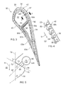
- FIG 3 is a section through an aerofoil 37 of the turbine blade 32 shown in Figure 2 and is in accordance with the present disclosure.
- the general arrangement of the aerofoil is equally applicable to the blade 32 or the vane 31.
- the aerofoil 37 of the turbine blade 32 comprises a pressure wall 40 and a suction wall 42 which meet at a leading edge 35 and at a trailing edge 36.
- the pressure wall 40 and the suction wall 42 define pressure and suction surfaces 44, 46 respectively.
- An internal web 48 extends between the pressure wall 40 and a suction wall 42 and which defines at least two main coolant passages 50, 52.
- the two main coolant passages 50, 52 are referred to as the leading edge main passage 50 and the trailing edge main passage 52; the respective main passages being adjacent the leading and trailing edges 35, 36 respectively.
- the web 48 may extend generally radially from the root 25 to the tip 38 defining two independent main passages. Coolant enters the main passage(s) via the root and flows generally radially outwardly towards the tip.
- the web 48 may extend between the root 25 and tip 38 and define a gap adjacent either or both the root or tip to allow coolant to pass in a multi-pass type arrangement as known in the art.
- coolant enters one main passage via the root and flows generally radially outwardly towards the tip before turning and flowing radially inwardly towards the root along another main passage; for example coolant may enter the leading edge main passage flow radially outward and then flow radially inwardly along the trailing edge main passage.
- coolant may enter the leading edge main passage flow radially outward and then flow radially inwardly along the trailing edge main passage.
- vanes may be fed coolant via the tip.
- the aerofoil 37 has a suction side wall 42 having an inner leaf 54 and an outer leaf 56 that define a cavity 58a.
- the pressure wall may be constructed similarly.
- the inner leaf 54 is an impingement plate and comprises an array of impingement holes 64 through which coolant can pass from the main coolant passage 52 and impinge on the outer leaf 56.
- the number and arrangement, including position and size of the impingement holes 64 are such that jets of coolant are directed at an inner surface of the outer leaf 56.
- the inner plate 54 might also be highly perforated and effective to separate a dedicated coolant flow in the cavity 58 from the main flow through the main passage 50 or 52.
- the pressure wall 40 defines an outlet 60a in its external gas-wash surface 44 and the aerofoil 37 defines a passage 62a extending from the cavity 58 through the web 48 and to the outlet 60a.
- part of the coolant entering one or both the main passage 50 or 52 passes through the impingement holes 64 and into the cavity 58 where at least a portion of the coolant in the cavity the passes along the passage 62a through the outlet 60a to be discharged across the external surface 44 to provide a protective coolant film.
- the inner leaf 54 and the outer leaf 56 can define a second cavity 58b and the pressure wall 40 (or suction wall 42) defines a second outlet 60b; the aerofoil defines a second passage 62b extending from the second cavity through the web 48 and to the second outlet 60b.
- the cavities 58a, 58b may extend the whole radial length between root 25 and tip 38 or only partially and there may be separate cavities positioned radially inwardly or outwardly of each other. These additional cavities may have dedicated passages and outlets.
- the embodiment used to describe the present aerofoil shows the suction wall 42 comprising the inner leaf and the outer leaf 56, which is the preferred embodiment.
- the pressure wall 40 may comprise the inner and outer leaves, while the suction surfaces defines the outlets.
- FIG. 4 is an enlarged view on section A-A shown in Figure 3 and illustrates the suction side wall 42
- Figure 5 which is a further enlarged view on part of Figure 4 .
- the wall comprises the cooling passages 58b that run in a generally chordal direction relative to the aerofoil.
- a surface 63 of the wall 42 in this case the internal surface, is comprises corrugations 65.
- the corrugations 65 are shown as smooth undulations in a generally sinusoidal profile section.
- the corrugations are generally arranged transverse a flow of gas 51 through the main coolant passage 50 of the aerofoil.
- the corrugations 65 comprise a peak 72, a trough 70, a downstream (facing) surface 74 and an upstream (facing) surface 76 with respect to coolant flow 51.
- the passages and cavities are arranged so as to reduce the overall temperature of the aerofoil and reduce the temperature gradients within the aerofoil walls and web via convective and impingement cooling, so reducing stresses and improving component life.
- debris, particles and other foreign objects may be carried in the coolant flow 51 and which can block small cooling holes such as the impingement holes 64.
- the upstream facing surface 76 deflects particles away from the wall surface 63 and therefore away from the holes 64.
- the inlet 66 on the downstream facing surface 74 particles do not have a direct line-of-sight to the inlet 66.
- vortices or turbulence can form in between peaks 72 and this causes an increase in static pressure adjacent the inlet 66 thereby helping promote entry of coolant into the inlet 66 and through passage 58b.
- the corrugations 65 are shown as generally sinusoidal, rounded triangular, trapezoidal or saw-toothed.
- the downstream surface 74 has an angle ⁇ to a line 78 which is in the general direction of coolant flow 51 or in the aerofoil of Fig 3 is generally radial to the engine centre line.
- the angle ⁇ shown is approximately 45°; however, angles between 20° and 90° are particularly useful.
- the downstream surface 76 has an angle ⁇ to the line 78.
- the angle ⁇ is approximately 45°; however, angles between 20° and 70° are particularly useful.
- the angles ⁇ and ⁇ need not be the same and therefore the corrugations 65 do not need to be symmetrical.
- the amplitude or height of the corrugations are approximately 0.7mm and the peak to peak distance is approximately 3mm. It is envisaged for gas turbine applications, the height of the corrugations may be between 0.5mm and 1.5mm and the distance between peaks between 2.5mm and 5mm.
- the centre-line 82 of the impingement hole 64 is shown at an angle ⁇ relative to the line 78.
- the angle ⁇ is such that the hole connects between the inlet and the position of the passage 58b.
- the angle ⁇ is between 30° and 90° and preferably about 45°.
- the centre-line 82 is shown off-set from a centre-line 80 of the passage 58b. This is advantageous in order to accommodate the passage 58b in the thickness of the wall 42. It may be preferably, where possible for the centre-line 82 to be coincident with the centre-line 80 of the passage 58b so that the impingement coolant strikes the passage walls at an as oblique angle as possible to maximise impingement cooling.
- the inlet 66 of the hole 64 is shown located approximately at a midpoint between peak 72 and trough 70; however, the hole may be located anywhere on the downstream surface 74 between the peak 72 and the trough 70.
- the passages 58b are generally triangular or rounded triangular.
- one apex 73 is arranged adjacent a peak 72 which helps to maintain a wall thickness.
- the passages 58b and 58a may be more compactly spaced.
- the passage 58b may be circular or any other manufacturable shape.
Landscapes
- Engineering & Computer Science (AREA)
- Mechanical Engineering (AREA)
- General Engineering & Computer Science (AREA)
- Turbine Rotor Nozzle Sealing (AREA)
Abstract
Description
- The present invention relates to a cooling arrangement of an aerofoil, such as in a blade or a vane, typically for a turbine stage of a gas turbine engine.
- The performance of gas turbine engines, whether measured in terms of efficiency or specific output, is improved by increasing the turbine gas temperature. It is therefore desirable to operate the turbines at the highest possible temperatures. For any engine cycle compression ratio or bypass ratio, increasing the turbine entry gas temperature produces more specific thrust (e.g. engine thrust per unit of air mass flow). However as turbine entry temperatures increase, the life of an un-cooled turbine falls, necessitating the development of better materials and the introduction of internal air cooling. In modern gas turbine engines, gas temperatures in a high-pressure turbine are hotter than the melting point of the material of the blades and vanes, necessitating internal air cooling of these aerofoil components.
- Conventional high-pressure nozzle guide vane (NGV) castings have a mixture of internal impingement cooling, convection cooling and external film cooling. Impingement cooling systems utilise impingement plates adjacent an external wall and have an array of small holes through which coolant flows to strike the inner surface of the external wall. Impingement plates may be either separate plate inserted to the aerofoil or integrally cast.
-
US7,600,973B discloses a conventional 'multi-pass' cooling system where coolant passes both radially inwardly and outwardly through main cooling passages. This design uses film cooling, internal turbulators and impingement cooling to cool its suction side aerofoil wall. However, coolant films over the suction side wall's external surface are penalizing on performance but they are necessary to make up for relatively inefficient internal cooling. - There is an ever increasing desire to improve cooling of components in gas turbine engines and especially high-pressure turbine vanes and blades. Improved cooling has many benefits including allowing increased gas temperatures and increased overall engine efficiency, increased life of components and/or decreased amount of cooling air that could otherwise be used for increased propulsive efficiency.
- It is therefore one of the objects of the present cooling arrangement to improve cooling effectiveness.
- Thus a first aspect of the present invention provides an aerofoil for a gas turbine engine, the aerofoil comprises a pressure wall and a suction wall, at least one of the pressure and suction walls comprise corrugations and a coolant hole on an inner surface, the corrugations define a downstream surface and the coolant hole having an inlet defined in the downstream surface.
- The corrugations may define an upstream surface.
- The wall may define a passage therein and the coolant hole connects between the inlet and the passage.
- A coolant may flow through the aerofoil and the downstream surface may be angled between 20° and 90° relative to the direction of coolant flow.
- A coolant may flow through the aerofoil and the downstream surface may be angled a is approximately 45° relative to the direction of coolant flow
- A coolant may flow through the aerofoil and the upstream surface may be angled θ between 20° and 70° relative to the direction of coolant flow.
- A coolant may flow through the aerofoil and the upstream surface may be angled θ is approximately 45° relative to the direction of coolant flow
- The corrugations may define any one or more the sectional profiles generally sinusoidal, rounded triangular, trapezoidal or saw-toothed.
- The corrugations define a peak and a cross-section of the passage may have an apex which is adjacent the peak.
- The corrugations may define an amplitude or height approximately 0.7mm.
- The corrugations may define an amplitude or height between 0.5mm and 1.5mm.
- The corrugations may define a peak to peak distance approximately 3mm.
- The corrugations may define a peak to peak distance between peaks between 2.5mm and 5mm.
- Embodiments of the invention will now be described by way of example with reference to the accompanying drawings in which:
-
Figure 1 shows a schematic longitudinal cross-section through a ducted fan gas turbine engine that may incorporate an aerofoil in accordance with the present disclosure; -
Figure 2 shows an isometric view of a typical single stage cooled turbine that may incorporate an aerofoil in accordance with the present disclosure; -
Figure 3 shows a section through an aerofoil shown inFigure 2 and is in accordance with the present disclosure; -
Figure 4 is an enlarged view on section A-A shown inFigure 3 and -
Figure 5 is a further enlarged view on part ofFigure 4 . - With reference to
Figure 1 , a ducted fan gas turbine engine generally indicated at 10 has a principal and rotational axis X-X. The terms radial, axial and circumferential are used with respect to this axis. The engine comprises, in axial flow series, anair intake 11, apropulsive fan 12, anintermediate pressure compressor 13, a high-pressure compressor 14,combustion equipment 15, a high-pressure turbine 16, an intermediate-pressure turbine 17, a low-pressure turbine 18 and a coreengine exhaust nozzle 19. Anacelle 21 generally surrounds theengine 10 and defines theintake 11, abypass duct 22 and abypass exhaust nozzle 23. - The
gas turbine engine 10 works in a conventional manner so that air entering theintake 11 is accelerated by thefan 12 to produce two air flows: a first air flow A into the intermediate pressure compressor 14 and a second air flow B which passes through thebypass duct 22 to provide propulsive thrust. Theintermediate pressure compressor 13 compresses the air flow A directed into it before delivering that air to the high pressure compressor 14 where further compression takes place. - The compressed air exhausted from the high-pressure compressor 14 is directed into the
combustion equipment 15 where it is mixed with fuel and the mixture combusted. The resultant hot combustion products then expand through, and thereby drive the high, intermediate and low-pressure turbines nozzle 19 to provide additional propulsive thrust. The high, intermediate and low-pressure turbines respectively drive the high andintermediate pressure compressors 14, 13 and thefan 12 by suitable interconnecting shafts. -
Figure 2 shows an isometric view of a typical single stage cooled turbine. In this example the high-pressure turbine 16 is shown. The high-pressure turbine 16 comprises an annular array of radially extendingstator vanes 31 and immediately downstream an annular array of radially extendingblades 32 mounted to arotor disc 26. The combustion gases impinge on the vanes which present the gases at an appropriate angle to efficiently drive the turbine blades. - The annular array of
stator vanes 31 is immediately downstream of thecombustor 15. The vanes therefore require significant cooling and typical cooling air flows are indicated by arrows. Internal convection and external cooling air films are the prime methods of cooling the gas path components -airfoils 37,platforms 33,shrouds 29 andshroud segments 35 etc. High-pressure turbine nozzle guide vanes 31 (NGVs) consume the greatest amount of cooling air on high temperature engines. High-pressure turbine blades 32 typically use about half of the NGV coolant flow. The intermediate-pressure and low-pressure stages downstream of the HP turbine use progressively less cooling air because the combustion gases become progressively cooler. - The high-pressure turbine airfoils are cooled by using high pressure air from one of the compressors, typically the high-pressure compressor, that has by-passed the combustor and is therefore relatively cool compared to the combustion or working gas temperature. Typical cooling air temperatures from the compressor are between 527°C (800K) and 727°C (1000K), while gas temperatures can be in excess of 1827°C (2100K).
- The cooling air from the compressor that is used to cool the hot turbine components is not used fully to extract work from the turbine. Therefore, as extracting coolant flow has an adverse effect on the engine operating efficiency and it is important to use the cooling air as effectively as possible.
- The
turbine blade 32 has aroot 25, aplatform 34, anaerofoil 37 andtip 38. Theroot 25 is in the form a 'fir-tree', as known in the art, and slots into a complimentary mounting on the rotor disc in known fashion. Other mounting configurations may be used. Theplatform 34 sits radially outwardly of theroot 25 and partly defines a gas-wash surface between adjacent blades. Theaerofoil 37 extends radially outwardly from the platform to thetip 38 and defines aerodynamic pressure and suction surfaces for the flow of combustion gases thereover. Thetip 38 helps to prevent over-tip leakage and can comprise sealing features. The tip may be in the form of a full or partial shroud or be shroudless. - Referring now to
Figure 3 , which is a section through anaerofoil 37 of theturbine blade 32 shown inFigure 2 and is in accordance with the present disclosure. The general arrangement of the aerofoil is equally applicable to theblade 32 or thevane 31. - The
aerofoil 37 of theturbine blade 32 comprises apressure wall 40 and asuction wall 42 which meet at aleading edge 35 and at a trailingedge 36. Thepressure wall 40 and thesuction wall 42 define pressure and suction surfaces 44, 46 respectively. - An
internal web 48 extends between thepressure wall 40 and asuction wall 42 and which defines at least twomain coolant passages Figure 3 the twomain coolant passages main passage 50 and the trailing edgemain passage 52; the respective main passages being adjacent the leading and trailingedges web 48 may extend generally radially from theroot 25 to thetip 38 defining two independent main passages. Coolant enters the main passage(s) via the root and flows generally radially outwardly towards the tip. Alternatively, theweb 48 may extend between theroot 25 andtip 38 and define a gap adjacent either or both the root or tip to allow coolant to pass in a multi-pass type arrangement as known in the art. In these arrangements coolant enters one main passage via the root and flows generally radially outwardly towards the tip before turning and flowing radially inwardly towards the root along another main passage; for example coolant may enter the leading edge main passage flow radially outward and then flow radially inwardly along the trailing edge main passage. It should be appreciated that there are many known possible multi-pass and single pass cooling flow systems within blades and vanes and the present disclosure may be applicable to those. For example vanes may be fed coolant via the tip. - The
aerofoil 37 has asuction side wall 42 having aninner leaf 54 and anouter leaf 56 that define acavity 58a. Alternatively or as well as, the pressure wall may be constructed similarly. Theinner leaf 54 is an impingement plate and comprises an array of impingement holes 64 through which coolant can pass from themain coolant passage 52 and impinge on theouter leaf 56. The number and arrangement, including position and size of the impingement holes 64 are such that jets of coolant are directed at an inner surface of theouter leaf 56. However, it is not necessary for theinner leaf 54 to be an impingement plate and a solid plate may be used with an inlet and an outlet adjacent theroot 25 andtip 38 or vice versa. Theinner plate 54 might also be highly perforated and effective to separate a dedicated coolant flow in the cavity 58 from the main flow through themain passage - The
pressure wall 40 defines anoutlet 60a in its external gas-wash surface 44 and theaerofoil 37 defines apassage 62a extending from the cavity 58 through theweb 48 and to theoutlet 60a. Thus part of the coolant entering one or both themain passage passage 62a through theoutlet 60a to be discharged across the external surface 44 to provide a protective coolant film. - The
inner leaf 54 and theouter leaf 56 can define asecond cavity 58b and the pressure wall 40 (or suction wall 42) defines a second outlet 60b; the aerofoil defines asecond passage 62b extending from the second cavity through theweb 48 and to the second outlet 60b. It should be appreciated that further sets of cavities, passages and outlets may be implemented with or without additional webs. For example, thecavities root 25 andtip 38 or only partially and there may be separate cavities positioned radially inwardly or outwardly of each other. These additional cavities may have dedicated passages and outlets. Furthermore, there may be more than oneweb 48 provided spanning between the pressure and suction walls. These arrangements may be useful where cooling requirements differ in areas of theaerofoil 37. - The embodiment used to describe the present aerofoil shows the
suction wall 42 comprising the inner leaf and theouter leaf 56, which is the preferred embodiment. However, depending on operational conditions, aerofoil configurations and potential implementation in compressor blades and vanes it is possible that thepressure wall 40 may comprise the inner and outer leaves, while the suction surfaces defines the outlets. - Referring now to
Figure 4 , which is an enlarged view on section A-A shown inFigure 3 and illustrates thesuction side wall 42, andFigure 5 , which is a further enlarged view on part ofFigure 4 . The wall comprises thecooling passages 58b that run in a generally chordal direction relative to the aerofoil. Asurface 63 of thewall 42, in this case the internal surface, is comprisescorrugations 65. Thecorrugations 65 are shown as smooth undulations in a generally sinusoidal profile section. The corrugations are generally arranged transverse a flow ofgas 51 through themain coolant passage 50 of the aerofoil. Thecorrugations 65 comprise apeak 72, atrough 70, a downstream (facing)surface 74 and an upstream (facing) surface 76 with respect tocoolant flow 51. - On the
downstream surface 74 there is defined aninlet 66 to theimpingement hole 64 which passes a portion of themain gas flow 51 into thecavity 58b. Thus the coolant flowing in a main passage is routed through thecavity 58b in thesuction wall 42, through theweb 48 which divides the leading edgemain passage 50 from the trailing edgemain passage 52 and into thepressure wall 40 before ejecting via film / effusion cooling holes oroutlets 60a, 60b. - The passages and cavities are arranged so as to reduce the overall temperature of the aerofoil and reduce the temperature gradients within the aerofoil walls and web via convective and impingement cooling, so reducing stresses and improving component life.
- In some circumstances, debris, particles and other foreign objects may be carried in the
coolant flow 51 and which can block small cooling holes such as the impingement holes 64. Here the arrangement of corrugations and inlet positions prevents debris, particles and other foreign objects from blocking theholes 64. The upstream facingsurface 76 deflects particles away from thewall surface 63 and therefore away from theholes 64. By placing theinlet 66 on the downstream facingsurface 74 particles do not have a direct line-of-sight to theinlet 66. Furthermore, vortices or turbulence can form in betweenpeaks 72 and this causes an increase in static pressure adjacent theinlet 66 thereby helping promote entry of coolant into theinlet 66 and throughpassage 58b. - In the exemplary embodiment shown in
Figure 5 thecorrugations 65 are shown as generally sinusoidal, rounded triangular, trapezoidal or saw-toothed. Thedownstream surface 74 has an angle α to aline 78 which is in the general direction ofcoolant flow 51 or in the aerofoil ofFig 3 is generally radial to the engine centre line. The angle α shown is approximately 45°; however, angles between 20° and 90° are particularly useful. Thedownstream surface 76 has an angle θ to theline 78. The angle θ is approximately 45°; however, angles between 20° and 70° are particularly useful. The angles α and θ need not be the same and therefore thecorrugations 65 do not need to be symmetrical. - Embodied in the exemplary embodiment shown in
Figures 3-5 , the amplitude or height of the corrugations (peak to trough) are approximately 0.7mm and the peak to peak distance is approximately 3mm. It is envisaged for gas turbine applications, the height of the corrugations may be between 0.5mm and 1.5mm and the distance between peaks between 2.5mm and 5mm. - The centre-
line 82 of theimpingement hole 64 is shown at an angle β relative to theline 78. The angle β is such that the hole connects between the inlet and the position of thepassage 58b. Typically, the angle β is between 30° and 90° and preferably about 45°. The centre-line 82 is shown off-set from a centre-line 80 of thepassage 58b. This is advantageous in order to accommodate thepassage 58b in the thickness of thewall 42. It may be preferably, where possible for the centre-line 82 to be coincident with the centre-line 80 of thepassage 58b so that the impingement coolant strikes the passage walls at an as oblique angle as possible to maximise impingement cooling. - The
inlet 66 of thehole 64 is shown located approximately at a midpoint betweenpeak 72 andtrough 70; however, the hole may be located anywhere on thedownstream surface 74 between the peak 72 and thetrough 70. - As shown in
Figure 4 thepassages 58b are generally triangular or rounded triangular. Advantageously one apex 73 is arranged adjacent apeak 72 which helps to maintain a wall thickness. Additionally, where thepassages 58b cross theweb 48 along withadjacent passages 58a, thepassages Figure 5 thepassage 58b may be circular or any other manufacturable shape. - While the invention has been described in conjunction with the exemplary embodiments described above, many equivalent modifications and variations will be apparent to those skilled in the art when given this disclosure. Accordingly, the exemplary embodiments of the invention set forth above are considered to be illustrative and not limiting. Various changes to the described embodiments may be made without departing from the spirit and scope of the invention.
Claims (13)
- An aerofoil (32) for a gas turbine engine,
the aerofoil comprises a pressure wall (40) and a suction wall (42),
at least one of the pressure and suction walls comprise corrugations (65) and a coolant hole (64) on an inner surface (63),
the corrugations define a downstream surface (74) with respect to a coolant flow (51) and the coolant hole having an inlet (66) defined in the downstream surface. - The aerofoil of claim 1 wherein the corrugations define an upstream surface (76).
- The aerofoil of any one of claims 1-2 wherein the wall defines a passage (58a, 58b) therein and the coolant hole connects between the inlet (66) and the passage.
- The aerofoil of any one of claims 1-3 wherein a coolant (51) flows through the aerofoil and the downstream surface is angled between 20° and 90° relative to the direction of coolant flow.
- The aerofoil of any one of claims 1-3 wherein a coolant (51) flows through the aerofoil and the downstream surface is angled α is approximately 45° relative to the direction of coolant flow
- The aerofoil of claims 2 wherein a coolant (51) flows through the aerofoil and the upstream surface is angled θ between 20° and 70° relative to the direction of coolant flow.
- The aerofoil of claim 2 wherein a coolant (51) flows through the aerofoil and the upstream surface is angled θ is approximately 45° relative to the direction of coolant flow
- The aerofoil of any one of claims 1-7 wherein the corrugations define any one or more the sectional profiles generally sinusoidal, rounded triangular, trapezoidal or saw-toothed.
- The aerofoil of claim 3 and any claim dependent on claim 3 wherein the corrugations define a peak (72) and a cross-section of the passage (58a, 58b) has an apex (73) which is adjacent the peak (72).
- The aerofoil of any one of claims 1-9 wherein the corrugations define an amplitude or height of the corrugations approximately 0.7mm.
- The aerofoil of any one of claims 1-9 wherein the corrugations define an amplitude or height of the corrugations between 0.5mm and 1.5mm.
- The aerofoil of any one of claims 1-11 wherein the corrugations define a peak (72) to peak distance approximately 3mm.
- The aerofoil of any one of claims 1-11 wherein the corrugations define a peak (72) to peak distance between peaks between 2.5mm and 5mm.
Applications Claiming Priority (1)
| Application Number | Priority Date | Filing Date | Title |
|---|---|---|---|
| GBGB1120273.6A GB201120273D0 (en) | 2011-11-24 | 2011-11-24 | Aerofoil cooling arrangement |
Publications (3)
| Publication Number | Publication Date |
|---|---|
| EP2597264A2 true EP2597264A2 (en) | 2013-05-29 |
| EP2597264A3 EP2597264A3 (en) | 2018-02-21 |
| EP2597264B1 EP2597264B1 (en) | 2021-05-19 |
Family
ID=45475648
Family Applications (1)
| Application Number | Title | Priority Date | Filing Date |
|---|---|---|---|
| EP12193456.6A Active EP2597264B1 (en) | 2011-11-24 | 2012-11-20 | Aerofoil cooling arrangement |
Country Status (3)
| Country | Link |
|---|---|
| US (1) | US9382811B2 (en) |
| EP (1) | EP2597264B1 (en) |
| GB (1) | GB201120273D0 (en) |
Cited By (2)
| Publication number | Priority date | Publication date | Assignee | Title |
|---|---|---|---|---|
| EP3168535B1 (en) * | 2015-11-13 | 2021-03-17 | Ansaldo Energia IP UK Limited | Aerodynamically shaped body and method for cooling a body provided in a hot fluid flow |
| WO2022214320A1 (en) * | 2021-04-08 | 2022-10-13 | Siemens Energy Global GmbH & Co. KG | Aerofoil and method |
Families Citing this family (8)
| Publication number | Priority date | Publication date | Assignee | Title |
|---|---|---|---|---|
| JP6245740B2 (en) * | 2013-11-20 | 2017-12-13 | 三菱日立パワーシステムズ株式会社 | Gas turbine blade |
| US20170306764A1 (en) * | 2016-04-26 | 2017-10-26 | General Electric Company | Airfoil for a turbine engine |
| US10895167B2 (en) | 2017-05-30 | 2021-01-19 | Raytheon Technologies Corporation | Metering hole geometry for cooling holes in gas turbine engine |
| KR101984397B1 (en) * | 2017-09-29 | 2019-05-30 | 두산중공업 주식회사 | Rotor, turbine and gas turbine comprising the same |
| EP3473808B1 (en) * | 2017-10-19 | 2020-06-17 | Siemens Aktiengesellschaft | Blade for an internally cooled turbine blade and method for producing same |
| US11078796B2 (en) | 2018-12-14 | 2021-08-03 | Raytheon Technologies Corporation | Redundant entry cooling air feed hole blockage preventer for a gas turbine engine |
| US11008872B2 (en) * | 2018-12-14 | 2021-05-18 | Raytheon Technologies Corporation | Extension air feed hole blockage preventer for a gas turbine engine |
| US11073024B2 (en) | 2018-12-14 | 2021-07-27 | Raytheon Technologies Corporation | Shape recessed surface cooling air feed hole blockage preventer for a gas turbine engine |
Family Cites Families (6)
| Publication number | Priority date | Publication date | Assignee | Title |
|---|---|---|---|---|
| US5405242A (en) | 1990-07-09 | 1995-04-11 | United Technologies Corporation | Cooled vane |
| US5816777A (en) * | 1991-11-29 | 1998-10-06 | United Technologies Corporation | Turbine blade cooling |
| US5271715A (en) | 1992-12-21 | 1993-12-21 | United Technologies Corporation | Cooled turbine blade |
| JP3651490B2 (en) | 1993-12-28 | 2005-05-25 | 株式会社東芝 | Turbine cooling blade |
| GB0523469D0 (en) | 2005-11-18 | 2005-12-28 | Rolls Royce Plc | Blades for gas turbine engines |
| GB0800361D0 (en) * | 2008-01-10 | 2008-02-20 | Rolls Royce Plc | Blade cooling |
-
2011
- 2011-11-24 GB GBGB1120273.6A patent/GB201120273D0/en not_active Ceased
-
2012
- 2012-11-20 US US13/682,028 patent/US9382811B2/en not_active Expired - Fee Related
- 2012-11-20 EP EP12193456.6A patent/EP2597264B1/en active Active
Non-Patent Citations (1)
| Title |
|---|
| None * |
Cited By (3)
| Publication number | Priority date | Publication date | Assignee | Title |
|---|---|---|---|---|
| EP3168535B1 (en) * | 2015-11-13 | 2021-03-17 | Ansaldo Energia IP UK Limited | Aerodynamically shaped body and method for cooling a body provided in a hot fluid flow |
| WO2022214320A1 (en) * | 2021-04-08 | 2022-10-13 | Siemens Energy Global GmbH & Co. KG | Aerofoil and method |
| US12331655B2 (en) | 2021-04-08 | 2025-06-17 | Siemens Energy Global GmbH & Co. KG | Aerofoil and method |
Also Published As
| Publication number | Publication date |
|---|---|
| EP2597264B1 (en) | 2021-05-19 |
| US20130136599A1 (en) | 2013-05-30 |
| GB201120273D0 (en) | 2012-01-04 |
| US9382811B2 (en) | 2016-07-05 |
| EP2597264A3 (en) | 2018-02-21 |
Similar Documents
| Publication | Publication Date | Title |
|---|---|---|
| US9382811B2 (en) | Aerofoil cooling arrangement | |
| US8721291B2 (en) | Flow directing member for gas turbine engine | |
| EP2746536A1 (en) | Rotor stage of a turbine | |
| US10641107B2 (en) | Turbine blade with tip overhang along suction side | |
| US8864452B2 (en) | Flow directing member for gas turbine engine | |
| EP2492454B1 (en) | Endwall component for a turbine stage of a gas turbine engine | |
| US20090317258A1 (en) | Rotor blade | |
| US7850428B2 (en) | Aerofoils | |
| US8573925B2 (en) | Cooled component for a gas turbine engine | |
| EP3415719B1 (en) | Turbomachine blade cooling structure | |
| US9512782B2 (en) | Gas turbine engine end-wall component | |
| US10830082B2 (en) | Systems including rotor blade tips and circumferentially grooved shrouds | |
| EP3184742B1 (en) | Turbine airfoil with trailing edge cooling circuit | |
| EP2825748A1 (en) | Improved cooling pedestal array | |
| EP2235328A1 (en) | Blade cooling | |
| US8297925B2 (en) | Aerofoil configuration | |
| KR102944040B1 (en) | Turbomachine rotor blade | |
| EP3329100B1 (en) | Cooling arrangements in tip shrouded turbine rotor blades | |
| US9376918B2 (en) | Aerofoil cooling arrangement | |
| US9200535B2 (en) | Aerofoil blade or vane | |
| JP2024546328A (en) | Gas turbine nozzle having cooling holes and turbine |
Legal Events
| Date | Code | Title | Description |
|---|---|---|---|
| PUAI | Public reference made under article 153(3) epc to a published international application that has entered the european phase |
Free format text: ORIGINAL CODE: 0009012 |
|
| AK | Designated contracting states |
Kind code of ref document: A2 Designated state(s): AL AT BE BG CH CY CZ DE DK EE ES FI FR GB GR HR HU IE IS IT LI LT LU LV MC MK MT NL NO PL PT RO RS SE SI SK SM TR |
|
| AX | Request for extension of the european patent |
Extension state: BA ME |
|
| RAP1 | Party data changed (applicant data changed or rights of an application transferred) |
Owner name: ROLLS-ROYCE PLC |
|
| PUAL | Search report despatched |
Free format text: ORIGINAL CODE: 0009013 |
|
| AK | Designated contracting states |
Kind code of ref document: A3 Designated state(s): AL AT BE BG CH CY CZ DE DK EE ES FI FR GB GR HR HU IE IS IT LI LT LU LV MC MK MT NL NO PL PT RO RS SE SI SK SM TR |
|
| AX | Request for extension of the european patent |
Extension state: BA ME |
|
| RIC1 | Information provided on ipc code assigned before grant |
Ipc: F01D 5/18 20060101AFI20180116BHEP |
|
| STAA | Information on the status of an ep patent application or granted ep patent |
Free format text: STATUS: REQUEST FOR EXAMINATION WAS MADE |
|
| 17P | Request for examination filed |
Effective date: 20180814 |
|
| RBV | Designated contracting states (corrected) |
Designated state(s): AL AT BE BG CH CY CZ DE DK EE ES FI FR GB GR HR HU IE IS IT LI LT LU LV MC MK MT NL NO PL PT RO RS SE SI SK SM TR |
|
| STAA | Information on the status of an ep patent application or granted ep patent |
Free format text: STATUS: EXAMINATION IS IN PROGRESS |
|
| 17Q | First examination report despatched |
Effective date: 20190314 |
|
| RAP1 | Party data changed (applicant data changed or rights of an application transferred) |
Owner name: ROLLS-ROYCE PLC |
|
| GRAP | Despatch of communication of intention to grant a patent |
Free format text: ORIGINAL CODE: EPIDOSNIGR1 |
|
| STAA | Information on the status of an ep patent application or granted ep patent |
Free format text: STATUS: GRANT OF PATENT IS INTENDED |
|
| GRAS | Grant fee paid |
Free format text: ORIGINAL CODE: EPIDOSNIGR3 |
|
| INTG | Intention to grant announced |
Effective date: 20210316 |
|
| GRAA | (expected) grant |
Free format text: ORIGINAL CODE: 0009210 |
|
| STAA | Information on the status of an ep patent application or granted ep patent |
Free format text: STATUS: THE PATENT HAS BEEN GRANTED |
|
| AK | Designated contracting states |
Kind code of ref document: B1 Designated state(s): AL AT BE BG CH CY CZ DE DK EE ES FI FR GB GR HR HU IE IS IT LI LT LU LV MC MK MT NL NO PL PT RO RS SE SI SK SM TR |
|
| REG | Reference to a national code |
Ref country code: GB Ref legal event code: FG4D |
|
| REG | Reference to a national code |
Ref country code: CH Ref legal event code: EP |
|
| REG | Reference to a national code |
Ref country code: DE Ref legal event code: R096 Ref document number: 602012075596 Country of ref document: DE |
|
| REG | Reference to a national code |
Ref country code: AT Ref legal event code: REF Ref document number: 1394137 Country of ref document: AT Kind code of ref document: T Effective date: 20210615 |
|
| REG | Reference to a national code |
Ref country code: IE Ref legal event code: FG4D |
|
| REG | Reference to a national code |
Ref country code: LT Ref legal event code: MG9D |
|
| REG | Reference to a national code |
Ref country code: AT Ref legal event code: MK05 Ref document number: 1394137 Country of ref document: AT Kind code of ref document: T Effective date: 20210519 |
|
| REG | Reference to a national code |
Ref country code: NL Ref legal event code: MP Effective date: 20210519 |
|
| PG25 | Lapsed in a contracting state [announced via postgrant information from national office to epo] |
Ref country code: LT Free format text: LAPSE BECAUSE OF FAILURE TO SUBMIT A TRANSLATION OF THE DESCRIPTION OR TO PAY THE FEE WITHIN THE PRESCRIBED TIME-LIMIT Effective date: 20210519 Ref country code: FI Free format text: LAPSE BECAUSE OF FAILURE TO SUBMIT A TRANSLATION OF THE DESCRIPTION OR TO PAY THE FEE WITHIN THE PRESCRIBED TIME-LIMIT Effective date: 20210519 Ref country code: AT Free format text: LAPSE BECAUSE OF FAILURE TO SUBMIT A TRANSLATION OF THE DESCRIPTION OR TO PAY THE FEE WITHIN THE PRESCRIBED TIME-LIMIT Effective date: 20210519 Ref country code: BG Free format text: LAPSE BECAUSE OF FAILURE TO SUBMIT A TRANSLATION OF THE DESCRIPTION OR TO PAY THE FEE WITHIN THE PRESCRIBED TIME-LIMIT Effective date: 20210819 Ref country code: HR Free format text: LAPSE BECAUSE OF FAILURE TO SUBMIT A TRANSLATION OF THE DESCRIPTION OR TO PAY THE FEE WITHIN THE PRESCRIBED TIME-LIMIT Effective date: 20210519 |
|
| PG25 | Lapsed in a contracting state [announced via postgrant information from national office to epo] |
Ref country code: NO Free format text: LAPSE BECAUSE OF FAILURE TO SUBMIT A TRANSLATION OF THE DESCRIPTION OR TO PAY THE FEE WITHIN THE PRESCRIBED TIME-LIMIT Effective date: 20210819 Ref country code: PT Free format text: LAPSE BECAUSE OF FAILURE TO SUBMIT A TRANSLATION OF THE DESCRIPTION OR TO PAY THE FEE WITHIN THE PRESCRIBED TIME-LIMIT Effective date: 20210920 Ref country code: PL Free format text: LAPSE BECAUSE OF FAILURE TO SUBMIT A TRANSLATION OF THE DESCRIPTION OR TO PAY THE FEE WITHIN THE PRESCRIBED TIME-LIMIT Effective date: 20210519 Ref country code: ES Free format text: LAPSE BECAUSE OF FAILURE TO SUBMIT A TRANSLATION OF THE DESCRIPTION OR TO PAY THE FEE WITHIN THE PRESCRIBED TIME-LIMIT Effective date: 20210519 Ref country code: IS Free format text: LAPSE BECAUSE OF FAILURE TO SUBMIT A TRANSLATION OF THE DESCRIPTION OR TO PAY THE FEE WITHIN THE PRESCRIBED TIME-LIMIT Effective date: 20210919 Ref country code: GR Free format text: LAPSE BECAUSE OF FAILURE TO SUBMIT A TRANSLATION OF THE DESCRIPTION OR TO PAY THE FEE WITHIN THE PRESCRIBED TIME-LIMIT Effective date: 20210820 Ref country code: LV Free format text: LAPSE BECAUSE OF FAILURE TO SUBMIT A TRANSLATION OF THE DESCRIPTION OR TO PAY THE FEE WITHIN THE PRESCRIBED TIME-LIMIT Effective date: 20210519 Ref country code: RS Free format text: LAPSE BECAUSE OF FAILURE TO SUBMIT A TRANSLATION OF THE DESCRIPTION OR TO PAY THE FEE WITHIN THE PRESCRIBED TIME-LIMIT Effective date: 20210519 Ref country code: SE Free format text: LAPSE BECAUSE OF FAILURE TO SUBMIT A TRANSLATION OF THE DESCRIPTION OR TO PAY THE FEE WITHIN THE PRESCRIBED TIME-LIMIT Effective date: 20210519 |
|
| PG25 | Lapsed in a contracting state [announced via postgrant information from national office to epo] |
Ref country code: NL Free format text: LAPSE BECAUSE OF FAILURE TO SUBMIT A TRANSLATION OF THE DESCRIPTION OR TO PAY THE FEE WITHIN THE PRESCRIBED TIME-LIMIT Effective date: 20210519 |
|
| PG25 | Lapsed in a contracting state [announced via postgrant information from national office to epo] |
Ref country code: DK Free format text: LAPSE BECAUSE OF FAILURE TO SUBMIT A TRANSLATION OF THE DESCRIPTION OR TO PAY THE FEE WITHIN THE PRESCRIBED TIME-LIMIT Effective date: 20210519 Ref country code: EE Free format text: LAPSE BECAUSE OF FAILURE TO SUBMIT A TRANSLATION OF THE DESCRIPTION OR TO PAY THE FEE WITHIN THE PRESCRIBED TIME-LIMIT Effective date: 20210519 Ref country code: CZ Free format text: LAPSE BECAUSE OF FAILURE TO SUBMIT A TRANSLATION OF THE DESCRIPTION OR TO PAY THE FEE WITHIN THE PRESCRIBED TIME-LIMIT Effective date: 20210519 Ref country code: SM Free format text: LAPSE BECAUSE OF FAILURE TO SUBMIT A TRANSLATION OF THE DESCRIPTION OR TO PAY THE FEE WITHIN THE PRESCRIBED TIME-LIMIT Effective date: 20210519 Ref country code: SK Free format text: LAPSE BECAUSE OF FAILURE TO SUBMIT A TRANSLATION OF THE DESCRIPTION OR TO PAY THE FEE WITHIN THE PRESCRIBED TIME-LIMIT Effective date: 20210519 Ref country code: RO Free format text: LAPSE BECAUSE OF FAILURE TO SUBMIT A TRANSLATION OF THE DESCRIPTION OR TO PAY THE FEE WITHIN THE PRESCRIBED TIME-LIMIT Effective date: 20210519 |
|
| REG | Reference to a national code |
Ref country code: DE Ref legal event code: R097 Ref document number: 602012075596 Country of ref document: DE |
|
| PLBE | No opposition filed within time limit |
Free format text: ORIGINAL CODE: 0009261 |
|
| STAA | Information on the status of an ep patent application or granted ep patent |
Free format text: STATUS: NO OPPOSITION FILED WITHIN TIME LIMIT |
|
| 26N | No opposition filed |
Effective date: 20220222 |
|
| PG25 | Lapsed in a contracting state [announced via postgrant information from national office to epo] |
Ref country code: IS Free format text: LAPSE BECAUSE OF FAILURE TO SUBMIT A TRANSLATION OF THE DESCRIPTION OR TO PAY THE FEE WITHIN THE PRESCRIBED TIME-LIMIT Effective date: 20210919 Ref country code: AL Free format text: LAPSE BECAUSE OF FAILURE TO SUBMIT A TRANSLATION OF THE DESCRIPTION OR TO PAY THE FEE WITHIN THE PRESCRIBED TIME-LIMIT Effective date: 20210519 |
|
| REG | Reference to a national code |
Ref country code: DE Ref legal event code: R119 Ref document number: 602012075596 Country of ref document: DE |
|
| PG25 | Lapsed in a contracting state [announced via postgrant information from national office to epo] |
Ref country code: MC Free format text: LAPSE BECAUSE OF FAILURE TO SUBMIT A TRANSLATION OF THE DESCRIPTION OR TO PAY THE FEE WITHIN THE PRESCRIBED TIME-LIMIT Effective date: 20210519 |
|
| REG | Reference to a national code |
Ref country code: CH Ref legal event code: PL |
|
| GBPC | Gb: european patent ceased through non-payment of renewal fee |
Effective date: 20211120 |
|
| PG25 | Lapsed in a contracting state [announced via postgrant information from national office to epo] |
Ref country code: LU Free format text: LAPSE BECAUSE OF NON-PAYMENT OF DUE FEES Effective date: 20211120 Ref country code: IT Free format text: LAPSE BECAUSE OF FAILURE TO SUBMIT A TRANSLATION OF THE DESCRIPTION OR TO PAY THE FEE WITHIN THE PRESCRIBED TIME-LIMIT Effective date: 20210519 Ref country code: BE Free format text: LAPSE BECAUSE OF NON-PAYMENT OF DUE FEES Effective date: 20211130 |
|
| REG | Reference to a national code |
Ref country code: BE Ref legal event code: MM Effective date: 20211130 |
|
| PG25 | Lapsed in a contracting state [announced via postgrant information from national office to epo] |
Ref country code: LI Free format text: LAPSE BECAUSE OF NON-PAYMENT OF DUE FEES Effective date: 20211130 Ref country code: CH Free format text: LAPSE BECAUSE OF NON-PAYMENT OF DUE FEES Effective date: 20211130 |
|
| PG25 | Lapsed in a contracting state [announced via postgrant information from national office to epo] |
Ref country code: IE Free format text: LAPSE BECAUSE OF NON-PAYMENT OF DUE FEES Effective date: 20211120 Ref country code: GB Free format text: LAPSE BECAUSE OF NON-PAYMENT OF DUE FEES Effective date: 20211120 Ref country code: DE Free format text: LAPSE BECAUSE OF NON-PAYMENT OF DUE FEES Effective date: 20220601 |
|
| PG25 | Lapsed in a contracting state [announced via postgrant information from national office to epo] |
Ref country code: FR Free format text: LAPSE BECAUSE OF NON-PAYMENT OF DUE FEES Effective date: 20211130 |
|
| PG25 | Lapsed in a contracting state [announced via postgrant information from national office to epo] |
Ref country code: HU Free format text: LAPSE BECAUSE OF FAILURE TO SUBMIT A TRANSLATION OF THE DESCRIPTION OR TO PAY THE FEE WITHIN THE PRESCRIBED TIME-LIMIT; INVALID AB INITIO Effective date: 20121120 Ref country code: CY Free format text: LAPSE BECAUSE OF FAILURE TO SUBMIT A TRANSLATION OF THE DESCRIPTION OR TO PAY THE FEE WITHIN THE PRESCRIBED TIME-LIMIT Effective date: 20210519 |
|
| PG25 | Lapsed in a contracting state [announced via postgrant information from national office to epo] |
Ref country code: MK Free format text: LAPSE BECAUSE OF FAILURE TO SUBMIT A TRANSLATION OF THE DESCRIPTION OR TO PAY THE FEE WITHIN THE PRESCRIBED TIME-LIMIT Effective date: 20210519 |
|
| PG25 | Lapsed in a contracting state [announced via postgrant information from national office to epo] |
Ref country code: TR Free format text: LAPSE BECAUSE OF FAILURE TO SUBMIT A TRANSLATION OF THE DESCRIPTION OR TO PAY THE FEE WITHIN THE PRESCRIBED TIME-LIMIT Effective date: 20210519 |
|
| PG25 | Lapsed in a contracting state [announced via postgrant information from national office to epo] |
Ref country code: MT Free format text: LAPSE BECAUSE OF FAILURE TO SUBMIT A TRANSLATION OF THE DESCRIPTION OR TO PAY THE FEE WITHIN THE PRESCRIBED TIME-LIMIT Effective date: 20210519 |