EP2597251A1 - Entry tube system - Google Patents
Entry tube system Download PDFInfo
- Publication number
- EP2597251A1 EP2597251A1 EP12193461.6A EP12193461A EP2597251A1 EP 2597251 A1 EP2597251 A1 EP 2597251A1 EP 12193461 A EP12193461 A EP 12193461A EP 2597251 A1 EP2597251 A1 EP 2597251A1
- Authority
- EP
- European Patent Office
- Prior art keywords
- entry tube
- inner mandrel
- end section
- chamber
- downhole
- Prior art date
- Legal status (The legal status is an assumption and is not a legal conclusion. Google has not performed a legal analysis and makes no representation as to the accuracy of the status listed.)
- Granted
Links
- 239000012530 fluid Substances 0.000 claims abstract description 61
- 238000000034 method Methods 0.000 claims description 17
- 239000000463 material Substances 0.000 claims description 3
- 238000003466 welding Methods 0.000 description 5
- 230000037361 pathway Effects 0.000 description 4
- 230000000903 blocking effect Effects 0.000 description 2
- 238000004519 manufacturing process Methods 0.000 description 2
- 230000007246 mechanism Effects 0.000 description 2
- 230000003628 erosive effect Effects 0.000 description 1
- 230000006870 function Effects 0.000 description 1
- 239000002002 slurry Substances 0.000 description 1
- 239000007787 solid Substances 0.000 description 1
Images








Classifications
-
- E—FIXED CONSTRUCTIONS
- E21—EARTH OR ROCK DRILLING; MINING
- E21B—EARTH OR ROCK DRILLING; OBTAINING OIL, GAS, WATER, SOLUBLE OR MELTABLE MATERIALS OR A SLURRY OF MINERALS FROM WELLS
- E21B43/00—Methods or apparatus for obtaining oil, gas, water, soluble or meltable materials or a slurry of minerals from wells
- E21B43/02—Subsoil filtering
- E21B43/04—Gravelling of wells
-
- E—FIXED CONSTRUCTIONS
- E21—EARTH OR ROCK DRILLING; MINING
- E21B—EARTH OR ROCK DRILLING; OBTAINING OIL, GAS, WATER, SOLUBLE OR MELTABLE MATERIALS OR A SLURRY OF MINERALS FROM WELLS
- E21B17/00—Drilling rods or pipes; Flexible drill strings; Kellies; Drill collars; Sucker rods; Cables; Casings; Tubings
- E21B17/18—Pipes provided with plural fluid passages
Definitions
- the present invention relates to the field of downhole tools, and in particular to an entry tube system for use in a gravel pack.
- the invention generally relates to shunt tubes used in subsurface well completions, and particularly to systems that provide improved fluid entry into shunt tubes.
- Conduits providing alternate or secondary pathways are commonly used in well completions.
- the shunt tubes allow fluid to flow past and emerge beyond a blockage in a primary passageway.
- the single entrance to a shunt tube could be covered, blocked, or otherwise become inaccessible to the fluid, thereby preventing the shunt tube from performing its intended function.
- Such blockage could occur, for example, when the shunt tube happened to be positioned on the bottom wall of a horizontal bore.
- Other prior art embodiments provided multiple pathways by which fluid can enter alternate pathway conduits, spacing entrance tubes to prevent all of them from being simultaneously obstructed, covered, or otherwise blocked, but spaced entrance tubes limit the available open area to flow. Therefore, there is a continuing need for improved entrance mechanisms to provide improved access to the shunt tubes.
- Full or nearly full circumference fluid flow is provided into an entry tube, allowing fluid to enter a chamber and flow to one or more shunt tubes connected to a downhole end of the entry tube.
- the fluid can enter the opening in any orientation of the entry tube system, and flow through the chamber to be directed into the shunt tubes.
- a downhole tool comprising:
- the entry tube may be configured to allow fluid communication with the chamber about all of the circumference of the inner mandrel at the uphole end of the entry tube.
- the downhole tool may further comprise:
- the exit tube may extend through the downhole end of the entry tube into the chamber, and the guide member may comprise a channel formed in a portion of the tapered surface aligned with the exit tube.
- the downhole tool may further comprise:
- the entry tube may comprise an end section, disposed at the uphole end of the entry tube, and the guide member may comprise a nose section, affixed to the end section.
- the tapered surface may comprise a straight taper.
- the guide member may be formed of a material harder than the inner mandrel.
- the entry tube may comprise:
- the entry tube may further comprise:
- the entry tube may further comprise:
- the exit tube may be disposed with the downhole end section.
- the entry tube may further comprise:
- the member may be affixed to the inner mandrel.
- a single inlet into the chamber may be formed between the inner mandrel and the entry tube.
- the entry tube may be positioned on a completion string tubular by sliding the tubular through the inner mandrel.
- the inner mandrel may comprise connectors for connecting the entry tube to a completion string tubular.
- the entry tube may be positioned on the inner mandrel by sliding the inner mandrel through the entry tube during assembly of the downhole tool.
- the downhole tool may further comprise:
- the downhole tool may further comprise:
- the method may further comprise:
- the method may further comprise:
- Forming a chamber in an entry tube may further comprise:
- the method may further comprise:
- Forming an outlet from the chamber may comprise:
- Disposing an exit tube through the downhole end section may comprise:
- Forming a chamber in an entry tube may comprise:
- the method may further comprise:
- the method may further comprise:
- the method may further comprise:
- Affixing a support member between the inner mandrel and the entry tube may comprise:
- the method may further comprise:
- uphole generally means towards the surface of the well, while downhole means away from the surface of the well, regardless of the physical orientation of the wellbore.
- uphole may indicate a horizontal direction or a vertical direction, depending on the position at which the indication is made.
- FIG. 1 is an isometric view of an entry tube system 100 according to one embodiment, configured for use as a portion of a completion assembly for use in a well.
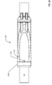
- FIG. 2 is an end view looking downhole at the entry tube system 100.
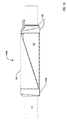
- FIG. 3 is a top view of the entry tube system 100
- FIG. 4 is a side view of the entry tube system 100; however, "top” and “side” are arbitrary orientations and should not be understood as referring to an orientation of the entry tube system in operation.
- the entry tube system 100 provides a large open area for fluid entry into one or more alternate path or shunt tubes 130, maximizing the open area to flow in the event of partial blockage, coverage, or obstruction.
- the entry tube system 100 may also cost less to manufacture than the prior art multiple entrance tube systems.
- the entry tube system 100 may be manufactured at any desired diameter and length.
- a guide member 120 is disposed about an inner mandrel 110.
- the guide member 120 and the inner mandrel 110 may be concentric about a longitudinal axis of the inner mandrel 110, or the guide member 120 may be eccentric to the inner mandrel 110.
- An uphole end section 160 is disposed at an uphole end of the inner mandrel, providing an entryway for fluid.
- a downhole end section 150 is disposed at the opposite or downhole end of the inner mandrel 110. Shown as transparent in FIG.
- a generally cylindrical cover section 140 is disposed about the inner mandrel 110 and guide member 120 between the uphole end section 160 and downhole end section 150, forming a chamber 170 through which fluid (not shown) may flow.
- the cover 140, downhole end section 150, and uphole end section 160 form an entry tube through which the inner mandrel extends to form the chamber 170.
- the uphole end section 160 may be omitted from the entry tube.
- the guide member 120 may extend from any first position along the inner mandrel 110 to the downhole end of the chamber 170.
- One or more shunt tubes 130 are disposed through the downhole end section 150, with the end of the shunt tubes 130 opening into the chamber 170.
- the shunt tubes 130 serve as exit tubes for the entry tube system 100. Although two shunt tubes 130 are illustrated in FIG. 1 , any number of shunt tubes 130 may be used as desired, including a single shunt tube 130.
- the uphole end section 160 is preferably formed with a rounded, beveled, or otherwise angled configuration in an uphole direction, to minimize the possibility of damaging or blocking the uphole end section 160 by contact with irregularities in the wellbore when the entry tube system is moved in an uphole direction.
- the downhole end section150 is preferably formed with a rounded, beveled, or otherwise angled configuration in a downhole direction, to minimize the possibility of damaging or blocking the downhole end section 150 by contact with irregularities in the wellbore when the entry tube system is moved in an downhole direction.
- the shapes of the uphole end section160 and downhole end section 150 as illustrated in FIGs. 1-4 are illustrative and by way of example only, and any desired shape may be used, including a squared off configuration.
- the outer diameter of the uphole end section 160, the downhole end section 150, and the cover section 140 may be substantially equal. As best illustrated in FIG. 4 , the ends of the cover section 140 may be beveled or otherwise reduced in diameter to allow a channel 410 for use when welding the cover section 140 to the uphole end section160 and the downhole end section 150. In another embodiment, instead of reducing the diameter of the ends of the cover section 140, the downhole end of the uphole end section 160 and the uphole end section of the downhole end section150 may be similarly reduced to provide the channel 410 for welding. In yet another embodiment, both the end sections 150, 160 and the cover section 140 may be tapered to form a notch for welding the elements together.
- the shunt tubes 130 may be formed with any desired cross-sectional configuration, including circular.
- the inner mandrel 110 is illustrated in FIGs. 1-4 as being eccentrically positioned relative to the cover section 140 and opening of the uphole end section160, as is best illustrated by FIGs. 2 and 4 . However, in one embodiment, the inner mandrel 110 may be disposed concentrically with those elements about a longitudinal axis 420 of the assembled entry tube system 100.
- the inner mandrel 110 may extend through or to an opening (not shown) in the downhole end section 150, allowing fluid flow through the inner mandrel 110 to other regions of the completion string as desired.
- the inner mandrel 110 may be sized to slip over a tubular of a completion string (not shown), allowing the entry tube system 100 to be positioned at any desired position on the completion string.
- the downhole end section 150, the uphole end section 160, and the guide member 120 may be movably positionable relative to a longitudinal axis of the inner mandrel.
- connectors may be formed in the uphole end section 160 and the downhole end section 150 for threadedly or otherwise connecting the uphole end section 160 and the downhole end section 150 to portions of the completion string.
- connectors may be formed on either end of the inner mandrel 110 for connecting the inner mandrel 110 to other portions of the completion string.
- any desired type of connector known to the art may be used.
- the inner mandrel 110 may be a portion of base pipe onto which the other elements may be positioned, as described in more detail in the discussion of FIGs. 13-20 .
- the guide member 120 is formed with a leading surface 124 that is generally tapered from the bottom of the inner mandrel 110 at the uphole end of the inner mandrel 110 to the top of the inner mandrel 110 at the downhole end of the inner mandrel 110.
- the taper of the leading surface 124 may be straight or curved as desired, such as a helical taper.
- the tapered leading surface 124 directs fluid entering through the uphole end section 160 into the chamber 170 around the inner mandrel110 towards the ends of the shunt tubes 130, regardless of the orientation of the entry tube system 100, as illustrated by example paths 300 in FIG. 3 .
- the guide member 120 may be formed of a material harder than the inner mandrel 110, to reduce erosion from the fluid guided into the shunt tubes 130 by the tapered surface 124.
- the taper of the tapered surface 124 may be as steep as desired, although a gradual taper is preferred to prevent fluid flow problems.
- channels 122 may be formed in the guide member 120 at a proximal to the shunt tubes 130 to further direct the flow of fluid through the channels 122 into the shunt tubes 130.
- an equal number of channels 122 and shunt tubes 130 may be used.
- a nose element 126 of the guide member 120 may extend beyond the uphole edge of the inner mandrel110 towards an uphole end of the uphole end section 160, to allow welding or otherwise affixing the guide member 120 to the uphole end section 160.
- the inner mandrel 110 is welded or otherwise affixed to the guide member 120, but is not welded or otherwise affixed to the uphole end section 160.
- the guide member 120 may be welded or otherwise affixed to the downhole end section 150.
- the uphole end of the inner mandrel 110 may be configured to key the inner mandrel 110 to the downhole end of the uphole end section 160, providing additional support.
- the guide member 120 may be omitted. In such an embodiment, the fluid would simply flow into the chamber 170 around the inner mandrel 110 into the shunt tubes 130, but would not be guided toward the shunt tubes as illustrated in FIGs. 1-4 .
- the inner mandrel 110 may be omitted.
- the chamber 170 is formed by the cover section 140, and the uphole end section 160 and downhole end section 150 may be connected to other portions of the completion string using any connection technique known to the art.
- the guide member 120 may be positioned in the chamber 170 without the inner mandrel110, wherein the tapered surface 124 is a solid tapered surface, instead of being formed around the circumference of the inner mandrel 110 as illustrated in FIG. 1 .
- the uphole ends of the shunt tubes 130 may be positioned flush with the uphole end of the downhole end section 150.
- the channels 122 may be omitted.
- FIG. 2 is an end view illustrating the entry tube system 100 of FIG. 1 according to one embodiment.
- the uphole end section 160 and inner mandrel110 form an inlet 200 that is eccentric relative to the circumference of the uphole end section 160, corresponding to the position of the inner mandrel 110.
- the inlet 200 allows flow of fluid around nearly the entire circumference of the inner mandre1110, except for the portion blocked by the nose element 126 of the guide member 120. The fluid may thus flow into the chamber 170, to be guided by the guide member 120 to the openings of the shunt tubes 130 for flow through the shunt tubes 130.
- the nose element 126 may be omitted and the inner mandrel 110 may be sealed to the inner diameter of the uphole end section 160 along a portion of the circumference of the inner mandrel 110.
- the inner mandrel 110 may be welded or otherwise affixed along that portion of the circumference of the inner mandrel 110 to provide additional support.
- the entry tube system 100 may include one or more elements to restrict fluid from entering the entry tube system 100 through the uphole end section 160 into the chamber 170 until shunt tubes130 are needed.
- restriction members such as valves or rupture discs may be placed across the uphole opening of the uphole end section 160, configured to allow fluid flow only if the pressure exceeds a predetermined threshold pressure.
- a fluid such as a gravel slurry or fracturing fluid is pumped into an annular region between a production zone of the well and the completion string.
- the fluid may be initially pumped through a work string down to a crossover mechanism which diverts the flow into the annular region some distance below the well surface.
- the fluid flows through the inlet 200 and through the chamber 170 into the shunt tubes 130.
- the inner mandrel 110 is of a smaller diameter than the internal diameter of the uphole end section 160, there is a fluid path through inlet 200 into chamber 170, and a guided fluid path in chamber 170 into the shunt tubes 130. That insures the fluid can pass into shunt tubes 130 regardless of the orientation of the entry tube system 100 in the wellbore.
- the fluid may be restricted from passing into the chamber 170 until the restriction devices are defeated.
- the relative size of the outer diameter of inner mandrel 110 to the inner diameter of the uphole end section 160 may be determined as desired, to vary the size of the inlet around the inner mandrel110 into the chamber 170.
- channels or ribs may be formed longitudinally on the inner mandrel110 to further guide the fluid toward the shunt tubes 130.
- FIGs. 5-8 illustrate another embodiment of an entry tube system.
- member 510 provides support for the cover section 140 at the uphole end of entry tube system 500.
- Member 510 may be welded or otherwise affixed to the cover section 140, the inner mandrel 110, or both, and prevents unwanted movement of the uphole end of the inner mandrel 110 relative to the cover section 140.
- the entry tube system 500 may be identical to the entry tube system 100.
- no uphole end section 160 is provided, but further embodiments may include a uphole end section 160 or other similar member to provide protection to the uphole end of the cover section 140 and/or inner mandrel 110, to avoid damage to the entry tube system 500 when moving the entry tube system 500 in an uphole direction and to provide non-squared surfaces to avoid catching the uphole end of the entry tube system 500 on projections from a casing or wellbore during uphole movement.
- the member 510 may be placed at any desired circumferential position about the inner mandrel 110, and multiple members 510 may be provided as desired. Although illustrated in FIGs.
- the member 510 may be offset downhole from the uphole edge a short distance as desired. As best illustrated in FIG. 6 , the member 510 may be sized to interfere minimally with flow of fluid through the inlet 610 formed into the chamber 170 between the uphole end of the inner mandrel 110 and the uphole end of the cover section 140. As best illustrated in FIG. 7 , the nose element 126 in this embodiment, if present, may extend only to the uphole edges of the inner mandrel 110 and cover section 140, and may be affixed to the inner mandrel 110.
- FIGs. 9-12 illustrate an entry tube system 900 according to yet another embodiment.
- an uphole end section 910 is formed with a plurality of integral support members 915 to provide support at a plurality of locations about the circumference of the inner mandrel 110.
- the entry tube system 900 may be identical to the entry tube system 100.
- multiple inlets 920 into the chamber 170 are formed by the placement of the integral support members 915 of the uphole end section 910.
- the integral support members 915 are preferably sloped in a downhole direction where they extend radially inward from the circumference of the uphole end section 910.
- three support members 915 are provided, any number, including one, may be provided.
- the support members 915 may extend downhole of the main portion of the uphole end section 910 into the chamber 170, providing additional support for the uphole end of the cover section 140.
- the chamber 170 continues to provide a single undifferentiated path through the chamber 170 about the inner mandrel 110 as in the other embodiments described herein.
- the combined multiple inlets 920 allow fluid communication about substantially all of the circumference of the inner mandrel 110.
- FIGs. 13-16 illustrated an entry tube system 1300 according to yet another embodiment.
- the uphole end of the inner mandrel 110 does not provide support to the uphole end section 1310 or the uphole end of the cover section 140.
- the entry tube system 1300 supports the inner mandrel110 at the downhole end of the entry tube system 1300.
- the entry tube system 1300 may be identical to the entry tube system 100.
- inner mandrel 110 may be formed by a section of base pipe that extends through the entry tube system 1300, and is connected to other portions of the completion string in any manner known to the art.
- a stop ring 1320 is disposed on the inner mandrel 110 at a predetermined location, and is affixed by welding or other techniques to the inner mandrel 110.
- the downhole end section 1330 is configured to mate with the stop ring 1320, allowing the entry tube system 1300 to be slid along the inner mandre1110 to the stop ring 1320, then welded or otherwise affixed to the stop ring 1320.
- Affixing the downhole end section 1330 to the stop ring 1320 provides support to keep the uphole end section 1310 and cover section 140 spaced away from the inner mandrel 110, forming a single full-circumference inlet 1410 about the inner mandrel 110 into the chamber 170, as best illustrated in FIG. 14 .
- the uphole end section 1310 may be omitted, similar to the embodiment illustrated in FIGs. 5-8 .
- any of the configurations of the uphole end illustrated in FIGs. 1-12 may be provided for additional support of the inner mandrel 110 and cover section 140.
- the uphole end of the guide member 120 may end downhole of the uphole end section 1310.
- the guide member 120 may extend to or through the uphole end section 1310, including providing a nose element 126 as illustrated in FIGs. 1-4 .
- FIGs. 17-20 illustrated an entry tube system 1700 according to yet another embodiment.
- the uphole end of the inner mandrel 110 provides support to the uphole end section 1710 and the cover section 140 by way of a keyed member 1720.
- the entry tube system 1700 may be identical to the entry tube system 1300.
- FIG. 19 is a cross-sectional view taken along line A-A of the entry tube system 1700.
- a keyed member 1720 is formed to be held between uphole end section 1710 and cover section 140, extending radially inward from those element to the inner mandrel 110 to provide support.
- the keyed member 1720 is welded to the uphole end section 1710 and/or cover section 140, but is not welded or otherwise affixed to the inner mandrel 110.
- the keyed member may 1720 be trapped between the uphole end section 1710 and cover section 140, without being welded to either.
- the keyed member1720 and inner mandrel 110 are slidably movable relative to each other when initially positioning the entry tube system 1700 along the inner mandrel 110 to the stop ring 1320, where the downhole end section 1330 may be welded or otherwise affixed to the stop ring 1320.
- the keyed member 1720 provides additional support, but is sized and configured to minimize interference with fluid flowing through the single inlet 1810 into the chamber 170 formed between the uphole end section 1710 and the inner mandrel 110, as best illustrated in FIG. 18 .
- the single inlet 1810 extends about the entire circumference of the inner mandrel 110.
- the guide member 120 may extend up to the downhole end of the uphole end section 1710, or may have a nose element 126 such as is illustrated in FIGs. 1-4 .
- the keyed member 1720 may extend into the chamber 170 to provide support to the cover section 140.
Landscapes
- Engineering & Computer Science (AREA)
- Geology (AREA)
- Life Sciences & Earth Sciences (AREA)
- Mining & Mineral Resources (AREA)
- Physics & Mathematics (AREA)
- Environmental & Geological Engineering (AREA)
- Fluid Mechanics (AREA)
- General Life Sciences & Earth Sciences (AREA)
- Geochemistry & Mineralogy (AREA)
- Mechanical Engineering (AREA)
- Pipe Accessories (AREA)
- Heat-Exchange Devices With Radiators And Conduit Assemblies (AREA)
- Rigid Pipes And Flexible Pipes (AREA)
- Branch Pipes, Bends, And The Like (AREA)
Abstract
Description
- The present invention relates to the field of downhole tools, and in particular to an entry tube system for use in a gravel pack.
- The invention generally relates to shunt tubes used in subsurface well completions, and particularly to systems that provide improved fluid entry into shunt tubes.
- Conduits providing alternate or secondary pathways (sometimes referred to as shunt tubes) for fluid flow are commonly used in well completions. The shunt tubes allow fluid to flow past and emerge beyond a blockage in a primary passageway. In some prior art embodiments, the single entrance to a shunt tube could be covered, blocked, or otherwise become inaccessible to the fluid, thereby preventing the shunt tube from performing its intended function. Such blockage could occur, for example, when the shunt tube happened to be positioned on the bottom wall of a horizontal bore. Other prior art embodiments provided multiple pathways by which fluid can enter alternate pathway conduits, spacing entrance tubes to prevent all of them from being simultaneously obstructed, covered, or otherwise blocked, but spaced entrance tubes limit the available open area to flow. Therefore, there is a continuing need for improved entrance mechanisms to provide improved access to the shunt tubes.
- Full or nearly full circumference fluid flow is provided into an entry tube, allowing fluid to enter a chamber and flow to one or more shunt tubes connected to a downhole end of the entry tube. The fluid can enter the opening in any orientation of the entry tube system, and flow through the chamber to be directed into the shunt tubes.
- According to one aspect of the invention there is provided a downhole tool, comprising:
- an entry tube;
- an inner mandrel, disposed within the entry tube, forming a chamber between the inner mandrel and an inner surface of the entry tube; and
- an exit tube, disposed at a downhole end of the entry tube, in fluid communication with the chamber,
- wherein the entry tube is configured to allow fluid communication with the chamber about substantially all of a circumference of the inner mandrel at an uphole end of the entry tube.
- The entry tube may be configured to allow fluid communication with the chamber about all of the circumference of the inner mandrel at the uphole end of the entry tube.
- The downhole tool may further comprise:
- a guide member, disposed about the inner mandrel in the chamber, comprising a tapered surface from a first position along the inner mandrel to the exit tube.
- The exit tube may extend through the downhole end of the entry tube into the chamber, and
the guide member may comprise a channel formed in a portion of the tapered surface aligned with the exit tube. - The downhole tool may further comprise:
- a downhole end section, disposed at a downhole end of the downhole tool, wherein the guide member is affixed to the downhole end section.
- The entry tube may comprise an end section, disposed at the uphole end of the entry tube, and
the guide member may comprise a nose section, affixed to the end section. - The tapered surface may comprise a straight taper.
- The guide member may be formed of a material harder than the inner mandrel.
- The entry tube may comprise:
- a cover section; and
- a downhole end section, disposed at a downhole end of the cover,
- wherein the chamber is formed between the inner mandrel and an inner surface of the cover.
- The entry tube may further comprise:
- an uphole end section, disposed at an uphole end of the cover.
- The entry tube may further comprise:
- a member disposed between the cover section and the inner mandrel,
- wherein the member is keyed to fit between the uphole end section and the cover section, and
- wherein the member and the inner mandrel are slidably moveable relative to each other during assembly of the downhole tool.
- The exit tube may be disposed with the downhole end section.
- The entry tube may further comprise:
- a member disposed between the cover section and the inner mandrel.
- The member may be affixed to the inner mandrel.
- A single inlet into the chamber may be formed between the inner mandrel and the entry tube.
- The entry tube may be positioned on a completion string tubular by sliding the tubular through the inner mandrel.
- The inner mandrel may comprise connectors for connecting the entry tube to a completion string tubular.
- The entry tube may be positioned on the inner mandrel by sliding the inner mandrel through the entry tube during assembly of the downhole tool.
- The downhole tool may further comprise:
- a restriction member, disposed with the uphole end of the entry tube, configured to prevent fluid flow into the chamber below a predetermined fluid pressure.
- The downhole tool may further comprise:
- a stop ring disposed at a predetermined position along the inner mandrel; and
- a downhole end section, disposed at a downhole end of the entry tube, configured to mate with the stop ring,
- wherein the downhole end section is affixed to the stop ring,
- wherein the inner mandrel comprises a section of base pipe.
- According to another aspect of the present invention there is provided a method, comprising:
- forming a chamber in an entry tube, comprising:
- disposing an inner mandrel within the entry tube, wherein the chamber is formed between an outer surface of the inner mandrel and an inner surface of the entry tube;
- providing fluid communication with the chamber about substantially all of a circumference of the inner mandrel at an uphole end of the entry tube; and
- forming an outlet from the chamber.
- The method may further comprise:
- guiding fluid to the outlet across a tapered surface disposed within the chamber.
- The method may further comprise:
- disposing an uphole end section at the uphole end of the entry tube; and
- affixing a nose of the tapered surface to the uphole end section.
- Forming a chamber in an entry tube may further comprise:
- forming a channel in a portion of the tapered surface proximal to the outlet, aligned with the outlet.
- The method may further comprise:
- guiding fluid flow about the surface of the inner mandrel.
- Forming an outlet from the chamber may comprise:
- disposing a downhole end section with a downhole end of the entry tube; and
- disposing an exit tube through the downhole end section, the exit tube in fluid communication with the chamber.
- Disposing an exit tube through the downhole end section may comprise:
- positioning an end of the exit tube flush with an inner surface of the downhole end section.
- Forming a chamber in an entry tube may comprise:
- disposing an uphole end section with the uphole end of the entry tube; and
- disposing a downhole end section with a downhole end of entry tube, and wherein forming an outlet from the chamber comprises:
- forming an opening in the downhole end section, in fluid communication with the chamber.
- The method may further comprise:
- restricting fluid entry into the chamber at pressures below a predetermined threshold pressure.
- The method may further comprise:
- disposing a stop ring at a predetermined position along the inner mandrel;
- disposing a downhole end section with a downhole end of the entry tube, the downhole end section configured to mate with the stop ring;
- sliding the entry tube and the downhole end section along the inner mandrel to mate with the stop ring; and
- affixing the downhole end section to the stop ring,
- wherein the inner mandrel comprises a section of base pipe.
- The method may further comprise:
- affixing a support member between the inner mandrel and the entry tube.
- Affixing a support member between the inner mandrel and the entry tube may comprise:
- disposing an uphole end section with the uphole end of the entry tube; and
- holding the support member between the uphole end section and the entry tube.
- The method may further comprise:
- forming an uphole end section configured for affixing to the uphole end of the entry tube,
- wherein the uphole end section comprises a support member configured to support the inner mandrel within the uphole end section.
- The accompanying drawings, which are incorporated in and constitute a part of this specification, illustrate an implementation of apparatus and methods consistent with the present invention and, together with the detailed description, serve to explain advantages and principles consistent with the invention. In the drawings,
-
Figure 1 is an isometric view of an entry tube system according to one embodiment. -
Figure 2 is an end view of the entry tube system ofFIG. 1 . -
Figure 3 is a top view of the entry tube system ofFIG. 1 . -
Figure 4 is a side view of the entry tube system ofFIG. 1 . -
Figure 5 is an isometric view of an entry tube system according to another embodiment. -
Figure 6 is an end view of the entry tube system ofFIG. 5 . -
Figure 7 is a top view of the entry tube system ofFIG. 5 . -
Figure 8 is a side view of the entry tube system ofFIG. 5 . -
Figure 9 is an isometric view of an entry tube system according to yet another embodiment. -
Figure 10 is an end view of the entry tube system ofFIG. 9 . -
Figure 11 is a top view of the entry tube system ofFIG. 9 . -
Figure 12 is a side view of the entry tube system ofFIG. 9 . -
Figure 13 is an isometric view of an entry tube system according to yet another embodiment. -
Figure 14 is an end view of the entry tube system ofFIG. 13 . -
Figure 15 is a top view of the entry tube system ofFIG. 13 . -
Figure 16 is a side view of the entry tube system ofFIG. 13 . -
Figure 17 is an isometric view of an entry tube system according to yet another embodiment. -
Figure 18 is an end view of the entry tube system ofFIG. 17 . -
Figure 19 is a top view of the entry tube system ofFIG. 17 . -
Figure 20 is a side view of the entry tube system ofFIG. 17 . - In the following description, for purposes of explanation, numerous specific details are set forth in order to provide a thorough understanding of the invention. It will be apparent, however, to one skilled in the art that the invention may be practiced without these specific details. References to numbers without subscripts or suffixes are understood to reference all instance of subscripts and suffixes corresponding to the referenced number. Moreover, the language used in this disclosure has been principally selected for readability and instructional purposes, and may not have been selected to delineate or circumscribe the inventive subject matter, resort to the claims being necessary to determine such inventive subject matter. Reference in the specification to "one embodiment" or to "an embodiment" means that a particular feature, structure, or characteristic described in connection with the embodiments is included in at least one embodiment of the invention, and multiple references to "one embodiment" or "an embodiment" should not be understood as necessarily all referring to the same embodiment.
- As used herein uphole generally means towards the surface of the well, while downhole means away from the surface of the well, regardless of the physical orientation of the wellbore. In a horizontally drilled well, for example, uphole may indicate a horizontal direction or a vertical direction, depending on the position at which the indication is made.
-
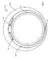
FIG. 1 is an isometric view of anentry tube system 100 according to one embodiment, configured for use as a portion of a completion assembly for use in a well.FIG. 2 is an end view looking downhole at theentry tube system 100.FIG. 3 is a top view of theentry tube system 100, andFIG. 4 is a side view of theentry tube system 100; however, "top" and "side" are arbitrary orientations and should not be understood as referring to an orientation of the entry tube system in operation. Theentry tube system 100 provides a large open area for fluid entry into one or more alternate path or shunttubes 130, maximizing the open area to flow in the event of partial blockage, coverage, or obstruction. Theentry tube system 100 may also cost less to manufacture than the prior art multiple entrance tube systems. - The
entry tube system 100 may be manufactured at any desired diameter and length. - As illustrated in
FIG. 1 , aguide member 120 is disposed about aninner mandrel 110. Theguide member 120 and theinner mandrel 110 may be concentric about a longitudinal axis of theinner mandrel 110, or theguide member 120 may be eccentric to theinner mandrel 110. Anuphole end section 160 is disposed at an uphole end of the inner mandrel, providing an entryway for fluid. Adownhole end section 150 is disposed at the opposite or downhole end of theinner mandrel 110. Shown as transparent inFIG. 1 to allow viewing the inner elements of theentry tube system 100, a generallycylindrical cover section 140 is disposed about theinner mandrel 110 and guidemember 120 between theuphole end section 160 anddownhole end section 150, forming achamber 170 through which fluid (not shown) may flow. Thecover 140,downhole end section 150, anduphole end section 160 form an entry tube through which the inner mandrel extends to form thechamber 170. In some embodiments discussed below, such as illustrated inFIGs. 5-8 , theuphole end section 160 may be omitted from the entry tube. - The
guide member 120 may extend from any first position along theinner mandrel 110 to the downhole end of thechamber 170. - One or
more shunt tubes 130 are disposed through thedownhole end section 150, with the end of theshunt tubes 130 opening into thechamber 170. Theshunt tubes 130 serve as exit tubes for theentry tube system 100. Although twoshunt tubes 130 are illustrated inFIG. 1 , any number ofshunt tubes 130 may be used as desired, including asingle shunt tube 130. - The
uphole end section 160 is preferably formed with a rounded, beveled, or otherwise angled configuration in an uphole direction, to minimize the possibility of damaging or blocking theuphole end section 160 by contact with irregularities in the wellbore when the entry tube system is moved in an uphole direction. Similarly, the downhole end section150 is preferably formed with a rounded, beveled, or otherwise angled configuration in a downhole direction, to minimize the possibility of damaging or blocking thedownhole end section 150 by contact with irregularities in the wellbore when the entry tube system is moved in an downhole direction. The shapes of the uphole end section160 anddownhole end section 150 as illustrated inFIGs. 1-4 are illustrative and by way of example only, and any desired shape may be used, including a squared off configuration. - The outer diameter of the
uphole end section 160, thedownhole end section 150, and thecover section 140 may be substantially equal. As best illustrated inFIG. 4 , the ends of thecover section 140 may be beveled or otherwise reduced in diameter to allow achannel 410 for use when welding thecover section 140 to the uphole end section160 and thedownhole end section 150. In another embodiment, instead of reducing the diameter of the ends of thecover section 140, the downhole end of theuphole end section 160 and the uphole end section of the downhole end section150 may be similarly reduced to provide thechannel 410 for welding. In yet another embodiment, both theend sections cover section 140 may be tapered to form a notch for welding the elements together. - Although illustrated in
FIGs. 1-4 with a substantially rectangular cross-section, theshunt tubes 130 may be formed with any desired cross-sectional configuration, including circular. - The
inner mandrel 110 is illustrated inFIGs. 1-4 as being eccentrically positioned relative to thecover section 140 and opening of the uphole end section160, as is best illustrated byFIGs. 2 and4 . However, in one embodiment, theinner mandrel 110 may be disposed concentrically with those elements about alongitudinal axis 420 of the assembledentry tube system 100. - The
inner mandrel 110 may extend through or to an opening (not shown) in thedownhole end section 150, allowing fluid flow through theinner mandrel 110 to other regions of the completion string as desired. In one embodiment, theinner mandrel 110 may be sized to slip over a tubular of a completion string (not shown), allowing theentry tube system 100 to be positioned at any desired position on the completion string. In another embodiment, thedownhole end section 150, theuphole end section 160, and theguide member 120 may be movably positionable relative to a longitudinal axis of the inner mandrel. In an alternate embodiment, connectors (not shown) may be formed in theuphole end section 160 and thedownhole end section 150 for threadedly or otherwise connecting theuphole end section 160 and thedownhole end section 150 to portions of the completion string. In yet another alternate embodiment, connectors (not shown) may be formed on either end of theinner mandrel 110 for connecting theinner mandrel 110 to other portions of the completion string. Where connectors are used to connect theentry tube system 100 to other portions of the completion string, any desired type of connector known to the art may be used. In one embodiment, theinner mandrel 110 may be a portion of base pipe onto which the other elements may be positioned, as described in more detail in the discussion ofFIGs. 13-20 . - The
guide member 120 is formed with a leadingsurface 124 that is generally tapered from the bottom of theinner mandrel 110 at the uphole end of theinner mandrel 110 to the top of theinner mandrel 110 at the downhole end of theinner mandrel 110. The taper of the leadingsurface 124 may be straight or curved as desired, such as a helical taper. The tapered leadingsurface 124 directs fluid entering through theuphole end section 160 into thechamber 170 around the inner mandrel110 towards the ends of theshunt tubes 130, regardless of the orientation of theentry tube system 100, as illustrated byexample paths 300 inFIG. 3 . - In one embodiment, the
guide member 120 may be formed of a material harder than theinner mandrel 110, to reduce erosion from the fluid guided into theshunt tubes 130 by the taperedsurface 124. - The taper of the tapered
surface 124 may be as steep as desired, although a gradual taper is preferred to prevent fluid flow problems. - In one embodiment,
channels 122 may be formed in theguide member 120 at a proximal to theshunt tubes 130 to further direct the flow of fluid through thechannels 122 into theshunt tubes 130. In such an embodiment, an equal number ofchannels 122 and shunttubes 130 may be used. - In one embodiment, a
nose element 126 of theguide member 120 may extend beyond the uphole edge of the inner mandrel110 towards an uphole end of theuphole end section 160, to allow welding or otherwise affixing theguide member 120 to theuphole end section 160. In one embodiment, theinner mandrel 110 is welded or otherwise affixed to theguide member 120, but is not welded or otherwise affixed to theuphole end section 160. In one embodiment, theguide member 120 may be welded or otherwise affixed to thedownhole end section 150. - In one embodiment, the uphole end of the
inner mandrel 110 may be configured to key theinner mandrel 110 to the downhole end of theuphole end section 160, providing additional support. - In another embodiment, the
guide member 120 may be omitted. In such an embodiment, the fluid would simply flow into thechamber 170 around theinner mandrel 110 into theshunt tubes 130, but would not be guided toward the shunt tubes as illustrated inFIGs. 1-4 . - In yet another embodiment, the
inner mandrel 110 may be omitted. In such an embodiment, thechamber 170 is formed by thecover section 140, and theuphole end section 160 anddownhole end section 150 may be connected to other portions of the completion string using any connection technique known to the art. In a further embodiment, theguide member 120 may be positioned in thechamber 170 without the inner mandrel110, wherein the taperedsurface 124 is a solid tapered surface, instead of being formed around the circumference of theinner mandrel 110 as illustrated inFIG. 1 . - In another embodiment, instead of extending into the
chamber 170 as illustrated inFIGS. 1-4 , the uphole ends of theshunt tubes 130 may be positioned flush with the uphole end of thedownhole end section 150. In such an embodiment, thechannels 122 may be omitted. -
FIG. 2 is an end view illustrating theentry tube system 100 ofFIG. 1 according to one embodiment. As illustrated, theuphole end section 160 and inner mandrel110 form aninlet 200 that is eccentric relative to the circumference of theuphole end section 160, corresponding to the position of theinner mandrel 110. As illustrated inFIG. 2 , theinlet 200 allows flow of fluid around nearly the entire circumference of the inner mandre1110, except for the portion blocked by thenose element 126 of theguide member 120. The fluid may thus flow into thechamber 170, to be guided by theguide member 120 to the openings of theshunt tubes 130 for flow through theshunt tubes 130. - In one embodiment, the
nose element 126 may be omitted and theinner mandrel 110 may be sealed to the inner diameter of theuphole end section 160 along a portion of the circumference of theinner mandrel 110. In another embodiment, theinner mandrel 110 may be welded or otherwise affixed along that portion of the circumference of theinner mandrel 110 to provide additional support. - Because
shunt tubes 130 are alternate pathway conduits, used to convey fluid past a blockage, theentry tube system 100 may include one or more elements to restrict fluid from entering theentry tube system 100 through theuphole end section 160 into thechamber 170 until shunt tubes130 are needed. In one embodiment, restriction members (not shown) such as valves or rupture discs may be placed across the uphole opening of theuphole end section 160, configured to allow fluid flow only if the pressure exceeds a predetermined threshold pressure. By using rupture discs, for example, fluid flow through theentry tube system 100 into theshunt tubes 130 would be prevented under normal operating pressures. However, if a blockage (bridging) occurred, pressure in the annular region could be increased until one or more discs burst at a predetermined pressure, allowing fluid to pass. - In operation, a fluid such as a gravel slurry or fracturing fluid is pumped into an annular region between a production zone of the well and the completion string. In some embodiments, the fluid may be initially pumped through a work string down to a crossover mechanism which diverts the flow into the annular region some distance below the well surface. When the fluid encounters the
entrance tube system 100, in the absence of restrictor devices the fluid flows through theinlet 200 and through thechamber 170 into theshunt tubes 130. Because theinner mandrel 110 is of a smaller diameter than the internal diameter of theuphole end section 160, there is a fluid path throughinlet 200 intochamber 170, and a guided fluid path inchamber 170 into theshunt tubes 130. That insures the fluid can pass intoshunt tubes 130 regardless of the orientation of theentry tube system 100 in the wellbore. In those embodiments employing restrictor devices, the fluid may be restricted from passing into thechamber 170 until the restriction devices are defeated. - The relative size of the outer diameter of
inner mandrel 110 to the inner diameter of theuphole end section 160 may be determined as desired, to vary the size of the inlet around the inner mandrel110 into thechamber 170. - In one embodiment, channels or ribs may be formed longitudinally on the inner mandrel110 to further guide the fluid toward the
shunt tubes 130. -
FIGs. 5-8 illustrate another embodiment of an entry tube system. As illustrated inFIGs. 5-8 ,member 510 provides support for thecover section 140 at the uphole end ofentry tube system 500.Member 510 may be welded or otherwise affixed to thecover section 140, theinner mandrel 110, or both, and prevents unwanted movement of the uphole end of theinner mandrel 110 relative to thecover section 140. Except for the uphole end of theentry tube system 500 as described below, theentry tube system 500 may be identical to theentry tube system 100. - As illustrated in
FIGs. 5-8 , nouphole end section 160 is provided, but further embodiments may include auphole end section 160 or other similar member to provide protection to the uphole end of thecover section 140 and/orinner mandrel 110, to avoid damage to theentry tube system 500 when moving theentry tube system 500 in an uphole direction and to provide non-squared surfaces to avoid catching the uphole end of theentry tube system 500 on projections from a casing or wellbore during uphole movement. Themember 510 may be placed at any desired circumferential position about theinner mandrel 110, andmultiple members 510 may be provided as desired. Although illustrated inFIGs. 5-8 disposed at the uphole edge of theinner mandrel 110 andcover section 140, themember 510 may be offset downhole from the uphole edge a short distance as desired. As best illustrated inFIG. 6 , themember 510 may be sized to interfere minimally with flow of fluid through theinlet 610 formed into thechamber 170 between the uphole end of theinner mandrel 110 and the uphole end of thecover section 140. As best illustrated inFIG. 7 , thenose element 126 in this embodiment, if present, may extend only to the uphole edges of theinner mandrel 110 andcover section 140, and may be affixed to theinner mandrel 110. -
FIGs. 9-12 illustrate anentry tube system 900 according to yet another embodiment. In this embodiment, anuphole end section 910 is formed with a plurality ofintegral support members 915 to provide support at a plurality of locations about the circumference of theinner mandrel 110. Except for the uphole end of theentry tube system 900 as described below, theentry tube system 900 may be identical to theentry tube system 100. - In this embodiment,
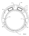
multiple inlets 920 into thechamber 170 are formed by the placement of theintegral support members 915 of theuphole end section 910. Theintegral support members 915 are preferably sloped in a downhole direction where they extend radially inward from the circumference of theuphole end section 910. Although as best illustrated inFIG. 10 , threesupport members 915 are provided, any number, including one, may be provided. - As best illustrated by
FIGs. 11 and12 , thesupport members 915 may extend downhole of the main portion of theuphole end section 910 into thechamber 170, providing additional support for the uphole end of thecover section 140. Although in this embodiment there aremultiple inlets 920 into thechamber 170, thechamber 170 continues to provide a single undifferentiated path through thechamber 170 about theinner mandrel 110 as in the other embodiments described herein. In addition, the combinedmultiple inlets 920 allow fluid communication about substantially all of the circumference of theinner mandrel 110. -
FIGs. 13-16 illustrated anentry tube system 1300 according to yet another embodiment. In this embodiment, the uphole end of theinner mandrel 110 does not provide support to theuphole end section 1310 or the uphole end of thecover section 140. Instead, theentry tube system 1300 supports the inner mandrel110 at the downhole end of theentry tube system 1300. Except as described below, theentry tube system 1300 may be identical to theentry tube system 100. In this embodiment,inner mandrel 110 may be formed by a section of base pipe that extends through theentry tube system 1300, and is connected to other portions of the completion string in any manner known to the art. - In this embodiment, a
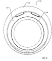
stop ring 1320 is disposed on theinner mandrel 110 at a predetermined location, and is affixed by welding or other techniques to theinner mandrel 110. Thedownhole end section 1330 is configured to mate with thestop ring 1320, allowing theentry tube system 1300 to be slid along the inner mandre1110 to thestop ring 1320, then welded or otherwise affixed to thestop ring 1320. Affixing thedownhole end section 1330 to thestop ring 1320 provides support to keep theuphole end section 1310 andcover section 140 spaced away from theinner mandrel 110, forming a single full-circumference inlet 1410 about theinner mandrel 110 into thechamber 170, as best illustrated inFIG. 14 . - Although as illustrated in
FIGs. 13-16 with anuphole end section 1310, in one embodiment, theuphole end section 1310 may be omitted, similar to the embodiment illustrated inFIGs. 5-8 . In other embodiments, any of the configurations of the uphole end illustrated inFIGs. 1-12 may be provided for additional support of theinner mandrel 110 andcover section 140. - As best illustrated in
FIG. 15 , in one embodiment, the uphole end of theguide member 120 may end downhole of theuphole end section 1310. In other embodiments, theguide member 120 may extend to or through theuphole end section 1310, including providing anose element 126 as illustrated inFIGs. 1-4 . -
FIGs. 17-20 illustrated anentry tube system 1700 according to yet another embodiment. In this embodiment, the uphole end of theinner mandrel 110 provides support to theuphole end section 1710 and thecover section 140 by way of akeyed member 1720. Except as described below, theentry tube system 1700 may be identical to theentry tube system 1300. -
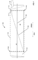
FIG. 19 is a cross-sectional view taken along line A-A of theentry tube system 1700. Akeyed member 1720 is formed to be held betweenuphole end section 1710 andcover section 140, extending radially inward from those element to theinner mandrel 110 to provide support. In one embodiment, thekeyed member 1720 is welded to theuphole end section 1710 and/orcover section 140, but is not welded or otherwise affixed to theinner mandrel 110. In other embodiments, the keyed member may 1720 be trapped between theuphole end section 1710 andcover section 140, without being welded to either. Thus, the keyed member1720 andinner mandrel 110 are slidably movable relative to each other when initially positioning theentry tube system 1700 along theinner mandrel 110 to thestop ring 1320, where thedownhole end section 1330 may be welded or otherwise affixed to thestop ring 1320. - In this embodiment, the
keyed member 1720 provides additional support, but is sized and configured to minimize interference with fluid flowing through thesingle inlet 1810 into thechamber 170 formed between theuphole end section 1710 and theinner mandrel 110, as best illustrated inFIG. 18 . As with theinlet 1410 of theentry tube system 1300 ofFIGs. 13-16 , thesingle inlet 1810 extends about the entire circumference of theinner mandrel 110. As with the embodiment ofFIGs. 13-16 , in this embodiment theguide member 120 may extend up to the downhole end of theuphole end section 1710, or may have anose element 126 such as is illustrated inFIGs. 1-4 . - As best illustrated in
FIG. 20 , thekeyed member 1720 may extend into thechamber 170 to provide support to thecover section 140. - It is to be understood that the above description is intended to be illustrative, and not restrictive. For example, the above-described embodiments may be used in combination with each other and elements of one embodiment may be combined with elements of other embodiments. Many other embodiments will be apparent to those of skill in the art upon reviewing the above description. The scope of the invention therefore should be determined with reference to the appended claims, along with the full scope of equivalents to which such claims are entitled. In the appended claims, the terms "including" and "in which" are used as the plain-English equivalents of the respective terms "comprising" and "wherein."
Claims (15)
- A downhole tool, comprising:an entry tube;an inner mandrel, disposed within the entry tube, forming a chamber between the inner mandrel and an inner surface of the entry tube; andan exit tube, disposed at a downhole end of the entry tube, in fluid communication with the chamber,wherein the entry tube is configured to allow fluid communication with the chamber about substantially all of a circumference of the inner mandrel at an uphole end of the entry tube.
- The downhole tool of claim 1, wherein the entry tube is configured to allow fluid communication with the chamber about all of the circumference of the inner mandrel at the uphole end of the entry tube.
- The downhole tool of claim 1 or 2, further comprising:a guide member, disposed about the inner mandrel in the chamber, comprising a tapered surface from a first position along the inner mandrel to the exit tube.
- The downhole tool of claim 3:(i) wherein the exit tube extends through the downhole end of the entry tube into the chamber, and
wherein the guide member comprises a channel formed in a portion of the tapered surface aligned with the exit tube, or(ii) further comprising:a downhole end section, disposed at a downhole end of the downhole tool,wherein the guide member is affixed to the downhole end section; or(iii) wherein the entry tube comprises an end section, disposed at the uphole end of the entry tube, and
wherein the guide member comprises a nose section, affixed to the end section; or(iv) wherein the tapered surface comprises a straight taper; or(v) wherein the guide member is formed of a material harder than the inner mandrel. - The downhole tool of claim 1, 2, 3 or 4, wherein the entry tube comprises:a cover section; anda downhole end section, disposed at a downhole end of the cover,wherein the chamber is formed between the inner mandrel and an inner surface of the cover.
- The downhole tool of claim 5, wherein the entry tube further comprises:an uphole end section, disposed at an uphole end of the cover, and optionally:(i) wherein the entry tube further comprises:a member disposed between the cover section and the inner mandrel,wherein the member is keyed to fit between the uphole end section and the cover section, andwherein the member and the inner mandrel are slidably moveable relative to each other during assembly of the downhole tool; or(ii) wherein the exit tube is disposed with the downhole end section.
- The downhole tool of claim 5 or 6, wherein the entry tube further comprises:a member disposed between the cover section and the inner mandrel, and optionally wherein the member is affixed to the inner mandrel.
- The downhole tool of any preceding claim,(i) wherein a single inlet into the chamber is formed between the inner mandrel and the entry tube, or(ii) wherein the entry tube is positioned on a completion string tubular by sliding the tubular through the inner mandrel, or(iii) wherein inner mandrel comprises connectors for connecting the entry tube to a completion string tubular, or(iv) wherein the entry tube is positioned on the inner mandrel by sliding the inner mandrel through the entry tube during assembly of the downhole tool.
- The downhole tool of any preceding claim,(i) further comprising:a restriction member, disposed with the uphole end of the entry tube, configured to prevent fluid flow into the chamber below a predetermined fluid pressure, or(ii) further comprising:a stop ring disposed at a predetermined position along the inner mandrel; anda downhole end section, disposed at a downhole end of the entry tube, configured to mate with the stop ring,wherein the downhole end section is affixed to the stop ring,wherein the inner mandrel comprises a section of base pipe.
- A method, comprising:forming a chamber in an entry tube, comprising:disposing an inner mandrel within the entry tube, wherein the chamber is formed between an outer surface of the inner mandrel and an inner surface of the entry tube;providing fluid communication with the chamber about substantially all of a circumference of the inner mandrel at an uphole end of the entry tube; andforming an outlet from the chamber.
- The method of claim 10, further comprising:guiding fluid to the outlet across a tapered surface disposed within the chamber, and optionally:(i) further comprising:disposing an uphole end section at the uphole end of the entry tube; andaffixing a nose of the tapered surface to the uphole end section, or(ii) wherein forming a chamber in an entry tube further comprises:forming a channel in a portion of the tapered surface proximal to the outlet, aligned with the outlet.
- The method of claim 10 or 11, further comprising:(i) guiding fluid flow about the surface of the inner mandrel, or(ii) restricting fluid entry into the chamber at pressures below a predetermined threshold pressure, or(iii) disposing a stop ring at a predetermined position along the inner mandrel; disposing a downhole end section with a downhole end of the entry tube, the downhole end section configured to mate with the stop ring;
sliding the entry tube and the downhole end section along the inner mandrel to mate with the stop ring; and
affixing the downhole end section to the stop ring,
wherein the inner mandrel comprises a section of base pipe; or(iv) forming an uphole end section configured for affixing to the uphole end of the entry tube,
wherein the uphole end section comprises a support member configured to support the inner mandrel within the uphole end section. - The method of claim 10, 11 or 12, wherein forming an outlet from the chamber comprises:disposing a downhole end section with a downhole end of the entry tube; anddisposing an exit tube through the downhole end section, the exit tube in fluid communication with the chamber, and optionallywherein disposing an exit tube through the downhole end section comprises:positioning an end of the exit tube flush with an inner surface of the downhole end section.
- The method of claim 10, 11, 12 or 13,
wherein forming a chamber in an entry tube comprises:disposing an uphole end section with the uphole end of the entry tube; anddisposing a downhole end section with a downhole end of entry tube, and wherein forming an outlet from the chamber comprises:forming an opening in the downhole end section, in fluid communication with the chamber. - The method of claim 10, 11, 12, 13 or 14, further comprising:affixing a support member between the inner mandrel and the entry tube, and optionallywherein affixing a support member between the inner mandrel and the entry tube comprises:disposing an uphole end section with the uphole end of the entry tube; andholding the support member between the uphole end section and the entry tube.
Applications Claiming Priority (1)
| Application Number | Priority Date | Filing Date | Title |
|---|---|---|---|
| US13/302,327 US9309751B2 (en) | 2011-11-22 | 2011-11-22 | Entry tube system |
Publications (2)
| Publication Number | Publication Date |
|---|---|
| EP2597251A1 true EP2597251A1 (en) | 2013-05-29 |
| EP2597251B1 EP2597251B1 (en) | 2017-10-04 |
Family
ID=47278157
Family Applications (1)
| Application Number | Title | Priority Date | Filing Date |
|---|---|---|---|
| EP12193461.6A Not-in-force EP2597251B1 (en) | 2011-11-22 | 2012-11-20 | Entry tube system |
Country Status (7)
| Country | Link |
|---|---|
| US (1) | US9309751B2 (en) |
| EP (1) | EP2597251B1 (en) |
| AU (1) | AU2012244199B2 (en) |
| BR (1) | BR102012029730B1 (en) |
| CA (1) | CA2794275C (en) |
| DK (1) | DK2597251T3 (en) |
| NO (1) | NO2597251T3 (en) |
Families Citing this family (3)
| Publication number | Priority date | Publication date | Assignee | Title |
|---|---|---|---|---|
| US10711579B2 (en) | 2017-11-16 | 2020-07-14 | Weatherford Technology Holdings, Llc | Erosion resistant shunt tube assembly for wellscreen |
| US10465485B2 (en) | 2017-11-16 | 2019-11-05 | Weatherford Technology Holdings, Llc | Erosion resistant shunt tube assembly for wellscreen |
| US11015419B2 (en) * | 2018-05-14 | 2021-05-25 | Bp Corporation North America Inc. | Bypass devices for a subterranean wellbore |
Citations (5)
| Publication number | Priority date | Publication date | Assignee | Title |
|---|---|---|---|---|
| GB2385616A (en) * | 2002-02-25 | 2003-08-27 | Schlumberger Holdings | A fluid transport system for use in a well |
| JP2004324085A (en) * | 2003-04-22 | 2004-11-18 | Tadayoshi Nagaoka | Joint structure of shunt tube screen and connection method for shunt tube screen |
| GB2414497A (en) * | 2003-09-03 | 2005-11-30 | Schlumberger Holdings | Shunt tube |
| EP2184436A2 (en) * | 2008-11-11 | 2010-05-12 | Swelltec Limited | Wellbore apparatus and method |
| WO2011119197A1 (en) * | 2010-03-25 | 2011-09-29 | Tunget Bruce A | Pressure controlled well construction and operation systems and methods usable for hydrocarbon operations, storage and solution mining |
Family Cites Families (10)
| Publication number | Priority date | Publication date | Assignee | Title |
|---|---|---|---|---|
| US5419394A (en) | 1993-11-22 | 1995-05-30 | Mobil Oil Corporation | Tools for delivering fluid to spaced levels in a wellbore |
| US5588487A (en) | 1995-09-12 | 1996-12-31 | Mobil Oil Corporation | Tool for blocking axial flow in gravel-packed well annulus |
| US5848645A (en) | 1996-09-05 | 1998-12-15 | Mobil Oil Corporation | Method for fracturing and gravel-packing a well |
| US5842516A (en) | 1997-04-04 | 1998-12-01 | Mobil Oil Corporation | Erosion-resistant inserts for fluid outlets in a well tool and method for installing same |
| US6220345B1 (en) * | 1999-08-19 | 2001-04-24 | Mobil Oil Corporation | Well screen having an internal alternate flowpath |
| US7213655B2 (en) * | 2004-01-15 | 2007-05-08 | Schlumberger Technology Corporation | System for connecting downhole tools |
| US7637318B2 (en) * | 2006-03-30 | 2009-12-29 | Halliburton Energy Services, Inc. | Pressure communication assembly external to casing with connectivity to pressure source |
| US20080283238A1 (en) * | 2007-05-16 | 2008-11-20 | William Mark Richards | Apparatus for autonomously controlling the inflow of production fluids from a subterranean well |
| US7946350B2 (en) | 2008-04-23 | 2011-05-24 | Schlumberger Technology Corporation | System and method for deploying optical fiber |
| WO2010028317A1 (en) * | 2008-09-05 | 2010-03-11 | Schlumberger Canada Limited | Shrouded tubular |
-
2011
- 2011-11-22 US US13/302,327 patent/US9309751B2/en active Active
-
2012
- 2012-10-29 AU AU2012244199A patent/AU2012244199B2/en not_active Ceased
- 2012-11-05 CA CA2794275A patent/CA2794275C/en not_active Expired - Fee Related
- 2012-11-20 DK DK12193461.6T patent/DK2597251T3/en active
- 2012-11-20 NO NO12193461A patent/NO2597251T3/no unknown
- 2012-11-20 EP EP12193461.6A patent/EP2597251B1/en not_active Not-in-force
- 2012-11-22 BR BR102012029730A patent/BR102012029730B1/en not_active IP Right Cessation
Patent Citations (5)
| Publication number | Priority date | Publication date | Assignee | Title |
|---|---|---|---|---|
| GB2385616A (en) * | 2002-02-25 | 2003-08-27 | Schlumberger Holdings | A fluid transport system for use in a well |
| JP2004324085A (en) * | 2003-04-22 | 2004-11-18 | Tadayoshi Nagaoka | Joint structure of shunt tube screen and connection method for shunt tube screen |
| GB2414497A (en) * | 2003-09-03 | 2005-11-30 | Schlumberger Holdings | Shunt tube |
| EP2184436A2 (en) * | 2008-11-11 | 2010-05-12 | Swelltec Limited | Wellbore apparatus and method |
| WO2011119197A1 (en) * | 2010-03-25 | 2011-09-29 | Tunget Bruce A | Pressure controlled well construction and operation systems and methods usable for hydrocarbon operations, storage and solution mining |
Also Published As
| Publication number | Publication date |
|---|---|
| BR102012029730A2 (en) | 2015-06-16 |
| AU2012244199B2 (en) | 2015-03-05 |
| DK2597251T3 (en) | 2017-12-18 |
| CA2794275C (en) | 2016-10-04 |
| BR102012029730A8 (en) | 2017-02-21 |
| NO2597251T3 (en) | 2018-03-03 |
| US20130126187A1 (en) | 2013-05-23 |
| US9309751B2 (en) | 2016-04-12 |
| BR102012029730B1 (en) | 2020-05-05 |
| CA2794275A1 (en) | 2013-05-22 |
| AU2012244199A1 (en) | 2013-06-06 |
| EP2597251B1 (en) | 2017-10-04 |
Similar Documents
| Publication | Publication Date | Title |
|---|---|---|
| US7207383B2 (en) | Multiple entrance shunt | |
| US6227298B1 (en) | Well isolation system | |
| CN103348096B (en) | Segmented collapsible ball seat allowing ball recovery | |
| RU2733998C2 (en) | Multistage stimulation device, systems and methods | |
| US9145758B2 (en) | Sleeved ball seat | |
| RU2611083C2 (en) | Rupturing coupling and positive indication of coupling opening for hydraulic fracturing | |
| CA2997142C (en) | Abrasive perforator with fluid bypass | |
| EP2859177B1 (en) | Shunt tube connection and distribution assembly and method | |
| EP2742206B1 (en) | Wellbore pressure control device | |
| US20120273055A1 (en) | Annular relief valve | |
| US20220243557A1 (en) | Wet-Mate Retrievable Filter System | |
| US20150027700A1 (en) | Sand control system and methodology | |
| CA2794275C (en) | Entry tube system | |
| WO2019090425A1 (en) | Flow control device for production tubing | |
| US10900324B2 (en) | Sliding sleeve having a flow inhibitor for well equalization | |
| RU2697440C1 (en) | Inflow control device comprising outward-configurable flow windows and erosion resistant deflectors | |
| US9068426B2 (en) | Fluid bypass for inflow control device tube | |
| EP3265640B1 (en) | Wellbore tubular and method | |
| US12203342B2 (en) | Wash tool apparatus and method of using the same | |
| WO2019068164A1 (en) | Flow control apparatus for wellbore stimulation and production | |
| CA2820283A1 (en) | Valve and method for hydraulic fracturing | |
| EP2960425A1 (en) | Drifting system | |
| US20130037256A1 (en) | Rotary Shoe Direct Fluid Flow System |
Legal Events
| Date | Code | Title | Description |
|---|---|---|---|
| PUAI | Public reference made under article 153(3) epc to a published international application that has entered the european phase |
Free format text: ORIGINAL CODE: 0009012 |
|
| 17P | Request for examination filed |
Effective date: 20121120 |
|
| AK | Designated contracting states |
Kind code of ref document: A1 Designated state(s): AL AT BE BG CH CY CZ DE DK EE ES FI FR GB GR HR HU IE IS IT LI LT LU LV MC MK MT NL NO PL PT RO RS SE SI SK SM TR |
|
| AX | Request for extension of the european patent |
Extension state: BA ME |
|
| RAP1 | Party data changed (applicant data changed or rights of an application transferred) |
Owner name: WEATHERFORD/LAMB, INC. |
|
| 17Q | First examination report despatched |
Effective date: 20140922 |
|
| RAP1 | Party data changed (applicant data changed or rights of an application transferred) |
Owner name: WEATHERFORD TECHNOLOGY HOLDINGS, LLC |
|
| GRAP | Despatch of communication of intention to grant a patent |
Free format text: ORIGINAL CODE: EPIDOSNIGR1 |
|
| INTG | Intention to grant announced |
Effective date: 20170526 |
|
| GRAS | Grant fee paid |
Free format text: ORIGINAL CODE: EPIDOSNIGR3 |
|
| GRAJ | Information related to disapproval of communication of intention to grant by the applicant or resumption of examination proceedings by the epo deleted |
Free format text: ORIGINAL CODE: EPIDOSDIGR1 |
|
| GRAL | Information related to payment of fee for publishing/printing deleted |
Free format text: ORIGINAL CODE: EPIDOSDIGR3 |
|
| INTC | Intention to grant announced (deleted) | ||
| GRAA | (expected) grant |
Free format text: ORIGINAL CODE: 0009210 |
|
| GRAR | Information related to intention to grant a patent recorded |
Free format text: ORIGINAL CODE: EPIDOSNIGR71 |
|
| AK | Designated contracting states |
Kind code of ref document: B1 Designated state(s): AL AT BE BG CH CY CZ DE DK EE ES FI FR GB GR HR HU IE IS IT LI LT LU LV MC MK MT NL NO PL PT RO RS SE SI SK SM TR |
|
| INTG | Intention to grant announced |
Effective date: 20170830 |
|
| REG | Reference to a national code |
Ref country code: GB Ref legal event code: FG4D |
|
| REG | Reference to a national code |
Ref country code: CH Ref legal event code: EP |
|
| REG | Reference to a national code |
Ref country code: AT Ref legal event code: REF Ref document number: 934243 Country of ref document: AT Kind code of ref document: T Effective date: 20171015 |
|
| REG | Reference to a national code |
Ref country code: IE Ref legal event code: FG4D |
|
| REG | Reference to a national code |
Ref country code: DE Ref legal event code: R096 Ref document number: 602012038068 Country of ref document: DE |
|
| REG | Reference to a national code |
Ref country code: DK Ref legal event code: T3 Effective date: 20171212 |
|
| REG | Reference to a national code |
Ref country code: NL Ref legal event code: FP |
|
| REG | Reference to a national code |
Ref country code: LT Ref legal event code: MG4D |
|
| REG | Reference to a national code |
Ref country code: NO Ref legal event code: T2 Effective date: 20171004 |
|
| REG | Reference to a national code |
Ref country code: AT Ref legal event code: MK05 Ref document number: 934243 Country of ref document: AT Kind code of ref document: T Effective date: 20171004 |
|
| PG25 | Lapsed in a contracting state [announced via postgrant information from national office to epo] |
Ref country code: SE Free format text: LAPSE BECAUSE OF FAILURE TO SUBMIT A TRANSLATION OF THE DESCRIPTION OR TO PAY THE FEE WITHIN THE PRESCRIBED TIME-LIMIT Effective date: 20171004 Ref country code: FI Free format text: LAPSE BECAUSE OF FAILURE TO SUBMIT A TRANSLATION OF THE DESCRIPTION OR TO PAY THE FEE WITHIN THE PRESCRIBED TIME-LIMIT Effective date: 20171004 Ref country code: ES Free format text: LAPSE BECAUSE OF FAILURE TO SUBMIT A TRANSLATION OF THE DESCRIPTION OR TO PAY THE FEE WITHIN THE PRESCRIBED TIME-LIMIT Effective date: 20171004 Ref country code: LT Free format text: LAPSE BECAUSE OF FAILURE TO SUBMIT A TRANSLATION OF THE DESCRIPTION OR TO PAY THE FEE WITHIN THE PRESCRIBED TIME-LIMIT Effective date: 20171004 |
|
| PG25 | Lapsed in a contracting state [announced via postgrant information from national office to epo] |
Ref country code: BG Free format text: LAPSE BECAUSE OF FAILURE TO SUBMIT A TRANSLATION OF THE DESCRIPTION OR TO PAY THE FEE WITHIN THE PRESCRIBED TIME-LIMIT Effective date: 20180104 Ref country code: GR Free format text: LAPSE BECAUSE OF FAILURE TO SUBMIT A TRANSLATION OF THE DESCRIPTION OR TO PAY THE FEE WITHIN THE PRESCRIBED TIME-LIMIT Effective date: 20180105 Ref country code: RS Free format text: LAPSE BECAUSE OF FAILURE TO SUBMIT A TRANSLATION OF THE DESCRIPTION OR TO PAY THE FEE WITHIN THE PRESCRIBED TIME-LIMIT Effective date: 20171004 Ref country code: LV Free format text: LAPSE BECAUSE OF FAILURE TO SUBMIT A TRANSLATION OF THE DESCRIPTION OR TO PAY THE FEE WITHIN THE PRESCRIBED TIME-LIMIT Effective date: 20171004 Ref country code: AT Free format text: LAPSE BECAUSE OF FAILURE TO SUBMIT A TRANSLATION OF THE DESCRIPTION OR TO PAY THE FEE WITHIN THE PRESCRIBED TIME-LIMIT Effective date: 20171004 Ref country code: HR Free format text: LAPSE BECAUSE OF FAILURE TO SUBMIT A TRANSLATION OF THE DESCRIPTION OR TO PAY THE FEE WITHIN THE PRESCRIBED TIME-LIMIT Effective date: 20171004 Ref country code: IS Free format text: LAPSE BECAUSE OF FAILURE TO SUBMIT A TRANSLATION OF THE DESCRIPTION OR TO PAY THE FEE WITHIN THE PRESCRIBED TIME-LIMIT Effective date: 20180204 |
|
| REG | Reference to a national code |
Ref country code: DE Ref legal event code: R119 Ref document number: 602012038068 Country of ref document: DE |
|
| PG25 | Lapsed in a contracting state [announced via postgrant information from national office to epo] |
Ref country code: MC Free format text: LAPSE BECAUSE OF FAILURE TO SUBMIT A TRANSLATION OF THE DESCRIPTION OR TO PAY THE FEE WITHIN THE PRESCRIBED TIME-LIMIT Effective date: 20171004 Ref country code: SK Free format text: LAPSE BECAUSE OF FAILURE TO SUBMIT A TRANSLATION OF THE DESCRIPTION OR TO PAY THE FEE WITHIN THE PRESCRIBED TIME-LIMIT Effective date: 20171004 Ref country code: EE Free format text: LAPSE BECAUSE OF FAILURE TO SUBMIT A TRANSLATION OF THE DESCRIPTION OR TO PAY THE FEE WITHIN THE PRESCRIBED TIME-LIMIT Effective date: 20171004 Ref country code: LI Free format text: LAPSE BECAUSE OF NON-PAYMENT OF DUE FEES Effective date: 20171130 Ref country code: CH Free format text: LAPSE BECAUSE OF NON-PAYMENT OF DUE FEES Effective date: 20171130 Ref country code: CZ Free format text: LAPSE BECAUSE OF FAILURE TO SUBMIT A TRANSLATION OF THE DESCRIPTION OR TO PAY THE FEE WITHIN THE PRESCRIBED TIME-LIMIT Effective date: 20171004 |
|
| PLBE | No opposition filed within time limit |
Free format text: ORIGINAL CODE: 0009261 |
|
| STAA | Information on the status of an ep patent application or granted ep patent |
Free format text: STATUS: NO OPPOSITION FILED WITHIN TIME LIMIT |
|
| PG25 | Lapsed in a contracting state [announced via postgrant information from national office to epo] |
Ref country code: IT Free format text: LAPSE BECAUSE OF FAILURE TO SUBMIT A TRANSLATION OF THE DESCRIPTION OR TO PAY THE FEE WITHIN THE PRESCRIBED TIME-LIMIT Effective date: 20171004 Ref country code: SM Free format text: LAPSE BECAUSE OF FAILURE TO SUBMIT A TRANSLATION OF THE DESCRIPTION OR TO PAY THE FEE WITHIN THE PRESCRIBED TIME-LIMIT Effective date: 20171004 Ref country code: PL Free format text: LAPSE BECAUSE OF FAILURE TO SUBMIT A TRANSLATION OF THE DESCRIPTION OR TO PAY THE FEE WITHIN THE PRESCRIBED TIME-LIMIT Effective date: 20171004 Ref country code: LU Free format text: LAPSE BECAUSE OF NON-PAYMENT OF DUE FEES Effective date: 20171120 Ref country code: RO Free format text: LAPSE BECAUSE OF FAILURE TO SUBMIT A TRANSLATION OF THE DESCRIPTION OR TO PAY THE FEE WITHIN THE PRESCRIBED TIME-LIMIT Effective date: 20171004 |
|
| REG | Reference to a national code |
Ref country code: FR Ref legal event code: ST Effective date: 20180731 Ref country code: BE Ref legal event code: MM Effective date: 20171130 |
|
| REG | Reference to a national code |
Ref country code: IE Ref legal event code: MM4A |
|
| 26N | No opposition filed |
Effective date: 20180705 |
|
| PG25 | Lapsed in a contracting state [announced via postgrant information from national office to epo] |
Ref country code: MT Free format text: LAPSE BECAUSE OF NON-PAYMENT OF DUE FEES Effective date: 20171120 |
|
| PG25 | Lapsed in a contracting state [announced via postgrant information from national office to epo] |
Ref country code: DE Free format text: LAPSE BECAUSE OF NON-PAYMENT OF DUE FEES Effective date: 20180602 Ref country code: IE Free format text: LAPSE BECAUSE OF NON-PAYMENT OF DUE FEES Effective date: 20171120 Ref country code: FR Free format text: LAPSE BECAUSE OF NON-PAYMENT OF DUE FEES Effective date: 20171204 |
|
| PG25 | Lapsed in a contracting state [announced via postgrant information from national office to epo] |
Ref country code: SI Free format text: LAPSE BECAUSE OF FAILURE TO SUBMIT A TRANSLATION OF THE DESCRIPTION OR TO PAY THE FEE WITHIN THE PRESCRIBED TIME-LIMIT Effective date: 20171004 Ref country code: BE Free format text: LAPSE BECAUSE OF NON-PAYMENT OF DUE FEES Effective date: 20171130 |
|
| PG25 | Lapsed in a contracting state [announced via postgrant information from national office to epo] |
Ref country code: HU Free format text: LAPSE BECAUSE OF FAILURE TO SUBMIT A TRANSLATION OF THE DESCRIPTION OR TO PAY THE FEE WITHIN THE PRESCRIBED TIME-LIMIT; INVALID AB INITIO Effective date: 20121120 |
|
| PG25 | Lapsed in a contracting state [announced via postgrant information from national office to epo] |
Ref country code: CY Free format text: LAPSE BECAUSE OF NON-PAYMENT OF DUE FEES Effective date: 20171004 |
|
| PG25 | Lapsed in a contracting state [announced via postgrant information from national office to epo] |
Ref country code: MK Free format text: LAPSE BECAUSE OF FAILURE TO SUBMIT A TRANSLATION OF THE DESCRIPTION OR TO PAY THE FEE WITHIN THE PRESCRIBED TIME-LIMIT Effective date: 20171004 |
|
| PGFP | Annual fee paid to national office [announced via postgrant information from national office to epo] |
Ref country code: NL Payment date: 20191114 Year of fee payment: 8 |
|
| PGFP | Annual fee paid to national office [announced via postgrant information from national office to epo] |
Ref country code: DK Payment date: 20191112 Year of fee payment: 8 |
|
| PG25 | Lapsed in a contracting state [announced via postgrant information from national office to epo] |
Ref country code: TR Free format text: LAPSE BECAUSE OF FAILURE TO SUBMIT A TRANSLATION OF THE DESCRIPTION OR TO PAY THE FEE WITHIN THE PRESCRIBED TIME-LIMIT Effective date: 20171004 |
|
| PG25 | Lapsed in a contracting state [announced via postgrant information from national office to epo] |
Ref country code: PT Free format text: LAPSE BECAUSE OF FAILURE TO SUBMIT A TRANSLATION OF THE DESCRIPTION OR TO PAY THE FEE WITHIN THE PRESCRIBED TIME-LIMIT Effective date: 20171004 |
|
| PG25 | Lapsed in a contracting state [announced via postgrant information from national office to epo] |
Ref country code: AL Free format text: LAPSE BECAUSE OF FAILURE TO SUBMIT A TRANSLATION OF THE DESCRIPTION OR TO PAY THE FEE WITHIN THE PRESCRIBED TIME-LIMIT Effective date: 20171004 |
|
| REG | Reference to a national code |
Ref country code: NL Ref legal event code: RC Free format text: DETAILS LICENCE OR PLEDGE: RIGHT OF PLEDGE, ESTABLISHED Name of requester: DEUTSCHE BANK TRUST COMPANY AMERICAS Effective date: 20200723 |
|
| REG | Reference to a national code |
Ref country code: GB Ref legal event code: 732E Free format text: REGISTERED BETWEEN 20200813 AND 20200819 |
|
| REG | Reference to a national code |
Ref country code: GB Ref legal event code: 732E Free format text: REGISTERED BETWEEN 20201126 AND 20201202 |
|
| REG | Reference to a national code |
Ref country code: GB Ref legal event code: 732E Free format text: REGISTERED BETWEEN 20210225 AND 20210303 |
|
| REG | Reference to a national code |
Ref country code: DK Ref legal event code: EBP Effective date: 20201130 |
|
| REG | Reference to a national code |
Ref country code: NL Ref legal event code: MM Effective date: 20201201 |
|
| PG25 | Lapsed in a contracting state [announced via postgrant information from national office to epo] |
Ref country code: NL Free format text: LAPSE BECAUSE OF NON-PAYMENT OF DUE FEES Effective date: 20201201 |
|
| PG25 | Lapsed in a contracting state [announced via postgrant information from national office to epo] |
Ref country code: DK Free format text: LAPSE BECAUSE OF NON-PAYMENT OF DUE FEES Effective date: 20201130 |
|
| PGFP | Annual fee paid to national office [announced via postgrant information from national office to epo] |
Ref country code: GB Payment date: 20210930 Year of fee payment: 10 |
|
| PGFP | Annual fee paid to national office [announced via postgrant information from national office to epo] |
Ref country code: NO Payment date: 20211109 Year of fee payment: 10 |
|
| REG | Reference to a national code |
Ref country code: NO Ref legal event code: MMEP |
|
| GBPC | Gb: european patent ceased through non-payment of renewal fee |
Effective date: 20221120 |
|
| PG25 | Lapsed in a contracting state [announced via postgrant information from national office to epo] |
Ref country code: NO Free format text: LAPSE BECAUSE OF NON-PAYMENT OF DUE FEES Effective date: 20221130 |
|
| PG25 | Lapsed in a contracting state [announced via postgrant information from national office to epo] |
Ref country code: GB Free format text: LAPSE BECAUSE OF NON-PAYMENT OF DUE FEES Effective date: 20221120 |