EP2597024A1 - Underwater floating device - Google Patents
Underwater floating device Download PDFInfo
- Publication number
- EP2597024A1 EP2597024A1 EP11306558.5A EP11306558A EP2597024A1 EP 2597024 A1 EP2597024 A1 EP 2597024A1 EP 11306558 A EP11306558 A EP 11306558A EP 2597024 A1 EP2597024 A1 EP 2597024A1
- Authority
- EP
- European Patent Office
- Prior art keywords
- floating device
- foam
- underwater floating
- insert
- thermoplastic material
- Prior art date
- Legal status (The legal status is an assumption and is not a legal conclusion. Google has not performed a legal analysis and makes no representation as to the accuracy of the status listed.)
- Granted
Links
- 239000006260 foam Substances 0.000 claims abstract description 53
- 239000012815 thermoplastic material Substances 0.000 claims abstract description 30
- XLYOFNOQVPJJNP-UHFFFAOYSA-N water Substances O XLYOFNOQVPJJNP-UHFFFAOYSA-N 0.000 claims abstract description 15
- 239000011152 fibreglass Substances 0.000 claims description 8
- 239000004743 Polypropylene Substances 0.000 claims description 6
- -1 polypropylene Polymers 0.000 claims description 6
- 229920001155 polypropylene Polymers 0.000 claims description 6
- 230000006835 compression Effects 0.000 claims description 3
- 238000007906 compression Methods 0.000 claims description 3
- 238000001746 injection moulding Methods 0.000 claims description 2
- 238000002347 injection Methods 0.000 description 15
- 239000007924 injection Substances 0.000 description 15
- 239000000463 material Substances 0.000 description 11
- 229920001187 thermosetting polymer Polymers 0.000 description 6
- 238000000034 method Methods 0.000 description 5
- 239000000853 adhesive Substances 0.000 description 4
- 230000001070 adhesive effect Effects 0.000 description 4
- 238000004519 manufacturing process Methods 0.000 description 4
- 239000003822 epoxy resin Substances 0.000 description 3
- 229920000647 polyepoxide Polymers 0.000 description 3
- 239000004814 polyurethane Substances 0.000 description 3
- 229920002635 polyurethane Polymers 0.000 description 3
- 238000002844 melting Methods 0.000 description 2
- 230000008018 melting Effects 0.000 description 2
- 239000004800 polyvinyl chloride Substances 0.000 description 2
- 229920000915 polyvinyl chloride Polymers 0.000 description 2
- 238000004064 recycling Methods 0.000 description 2
- 229920001169 thermoplastic Polymers 0.000 description 2
- 239000004416 thermosoftening plastic Substances 0.000 description 2
- 239000003086 colorant Substances 0.000 description 1
- 230000007812 deficiency Effects 0.000 description 1
- 230000004927 fusion Effects 0.000 description 1
- 230000000007 visual effect Effects 0.000 description 1
Images


Classifications
-
- B—PERFORMING OPERATIONS; TRANSPORTING
- B29—WORKING OF PLASTICS; WORKING OF SUBSTANCES IN A PLASTIC STATE IN GENERAL
- B29C—SHAPING OR JOINING OF PLASTICS; SHAPING OF MATERIAL IN A PLASTIC STATE, NOT OTHERWISE PROVIDED FOR; AFTER-TREATMENT OF THE SHAPED PRODUCTS, e.g. REPAIRING
- B29C45/00—Injection moulding, i.e. forcing the required volume of moulding material through a nozzle into a closed mould; Apparatus therefor
- B29C45/14—Injection moulding, i.e. forcing the required volume of moulding material through a nozzle into a closed mould; Apparatus therefor incorporating preformed parts or layers, e.g. injection moulding around inserts or for coating articles
-
- B—PERFORMING OPERATIONS; TRANSPORTING
- B63—SHIPS OR OTHER WATERBORNE VESSELS; RELATED EQUIPMENT
- B63B—SHIPS OR OTHER WATERBORNE VESSELS; EQUIPMENT FOR SHIPPING
- B63B21/00—Tying-up; Shifting, towing, or pushing equipment; Anchoring
- B63B21/56—Towing or pushing equipment
- B63B21/66—Equipment specially adapted for towing underwater objects or vessels, e.g. fairings for tow-cables
-
- B—PERFORMING OPERATIONS; TRANSPORTING
- B29—WORKING OF PLASTICS; WORKING OF SUBSTANCES IN A PLASTIC STATE IN GENERAL
- B29C—SHAPING OR JOINING OF PLASTICS; SHAPING OF MATERIAL IN A PLASTIC STATE, NOT OTHERWISE PROVIDED FOR; AFTER-TREATMENT OF THE SHAPED PRODUCTS, e.g. REPAIRING
- B29C44/00—Shaping by internal pressure generated in the material, e.g. swelling or foaming ; Producing porous or cellular expanded plastics articles
- B29C44/02—Shaping by internal pressure generated in the material, e.g. swelling or foaming ; Producing porous or cellular expanded plastics articles for articles of definite length, i.e. discrete articles
- B29C44/12—Incorporating or moulding on preformed parts, e.g. inserts or reinforcements
-
- B—PERFORMING OPERATIONS; TRANSPORTING
- B63—SHIPS OR OTHER WATERBORNE VESSELS; RELATED EQUIPMENT
- B63G—OFFENSIVE OR DEFENSIVE ARRANGEMENTS ON VESSELS; MINE-LAYING; MINE-SWEEPING; SUBMARINES; AIRCRAFT CARRIERS
- B63G8/00—Underwater vessels, e.g. submarines; Equipment specially adapted therefor
- B63G8/14—Control of attitude or depth
- B63G8/18—Control of attitude or depth by hydrofoils
-
- B—PERFORMING OPERATIONS; TRANSPORTING
- B29—WORKING OF PLASTICS; WORKING OF SUBSTANCES IN A PLASTIC STATE IN GENERAL
- B29K—INDEXING SCHEME ASSOCIATED WITH SUBCLASSES B29B, B29C OR B29D, RELATING TO MOULDING MATERIALS OR TO MATERIALS FOR MOULDS, REINFORCEMENTS, FILLERS OR PREFORMED PARTS, e.g. INSERTS
- B29K2023/00—Use of polyalkenes or derivatives thereof as moulding material
- B29K2023/10—Polymers of propylene
- B29K2023/12—PP, i.e. polypropylene
-
- B—PERFORMING OPERATIONS; TRANSPORTING
- B29—WORKING OF PLASTICS; WORKING OF SUBSTANCES IN A PLASTIC STATE IN GENERAL
- B29K—INDEXING SCHEME ASSOCIATED WITH SUBCLASSES B29B, B29C OR B29D, RELATING TO MOULDING MATERIALS OR TO MATERIALS FOR MOULDS, REINFORCEMENTS, FILLERS OR PREFORMED PARTS, e.g. INSERTS
- B29K2105/00—Condition, form or state of moulded material or of the material to be shaped
- B29K2105/04—Condition, form or state of moulded material or of the material to be shaped cellular or porous
- B29K2105/046—Condition, form or state of moulded material or of the material to be shaped cellular or porous with closed cells
-
- B—PERFORMING OPERATIONS; TRANSPORTING
- B63—SHIPS OR OTHER WATERBORNE VESSELS; RELATED EQUIPMENT
- B63B—SHIPS OR OTHER WATERBORNE VESSELS; EQUIPMENT FOR SHIPPING
- B63B2231/00—Material used for some parts or elements, or for particular purposes
- B63B2231/40—Synthetic materials
- B63B2231/50—Foamed synthetic materials
-
- B—PERFORMING OPERATIONS; TRANSPORTING
- B63—SHIPS OR OTHER WATERBORNE VESSELS; RELATED EQUIPMENT
- B63G—OFFENSIVE OR DEFENSIVE ARRANGEMENTS ON VESSELS; MINE-LAYING; MINE-SWEEPING; SUBMARINES; AIRCRAFT CARRIERS
- B63G8/00—Underwater vessels, e.g. submarines; Equipment specially adapted therefor
- B63G8/14—Control of attitude or depth
- B63G8/24—Automatic depth adjustment; Safety equipment for increasing buoyancy, e.g. detachable ballast, floating bodies
-
- B—PERFORMING OPERATIONS; TRANSPORTING
- B63—SHIPS OR OTHER WATERBORNE VESSELS; RELATED EQUIPMENT
- B63G—OFFENSIVE OR DEFENSIVE ARRANGEMENTS ON VESSELS; MINE-LAYING; MINE-SWEEPING; SUBMARINES; AIRCRAFT CARRIERS
- B63G8/00—Underwater vessels, e.g. submarines; Equipment specially adapted therefor
- B63G8/42—Towed underwater vessels
-
- G—PHYSICS
- G01—MEASURING; TESTING
- G01V—GEOPHYSICS; GRAVITATIONAL MEASUREMENTS; DETECTING MASSES OR OBJECTS; TAGS
- G01V1/00—Seismology; Seismic or acoustic prospecting or detecting
- G01V1/38—Seismology; Seismic or acoustic prospecting or detecting specially adapted for water-covered areas
- G01V1/3817—Positioning of seismic devices
-
- Y—GENERAL TAGGING OF NEW TECHNOLOGICAL DEVELOPMENTS; GENERAL TAGGING OF CROSS-SECTIONAL TECHNOLOGIES SPANNING OVER SEVERAL SECTIONS OF THE IPC; TECHNICAL SUBJECTS COVERED BY FORMER USPC CROSS-REFERENCE ART COLLECTIONS [XRACs] AND DIGESTS
- Y02—TECHNOLOGIES OR APPLICATIONS FOR MITIGATION OR ADAPTATION AGAINST CLIMATE CHANGE
- Y02T—CLIMATE CHANGE MITIGATION TECHNOLOGIES RELATED TO TRANSPORTATION
- Y02T10/00—Road transport of goods or passengers
- Y02T10/60—Other road transportation technologies with climate change mitigation effect
- Y02T10/72—Electric energy management in electromobility
Definitions
- the present invention relates to floating devices, in particular submarine or underwater floating devices.
- floating devices may be used in a marine environment, for example in the field of the acquisition of seismic data, oil or gas prospecting industry, marine research or offshore production.
- Such floating devices may consist in wings present in a navigation control device, also called « bird » for controlling the position of an instrumented cable towed in water, such as a marine seismic streamer, and/or the relative position of cables in a towed instrumented cable network of streamers.
- a navigation control device also called « bird » for controlling the position of an instrumented cable towed in water, such as a marine seismic streamer, and/or the relative position of cables in a towed instrumented cable network of streamers.
- Underwater floating devices are supposed to, simultaneously, float, be able to resist to high pressures due to the depth at which they are used and be able to resist mechanical loads.
- the floating devices are also supposed to be watertight. In case of damage, they should not be filled entirely with water.
- Techniques of seismic data acquisition usually require to tow streamers at depths comprised between 5 meters and 15 meters.
- New techniques of seismic data acquisition require now to tow streamers at depths that can reach 80 to 120 meters.
- the floating devices are therefore supposed to resist to pressures possibly reaching 1,2 MPa, i.e. until 12 bars.
- US 2010/037402 Another device of this type is disclosed in US 2010/037402 , which device comprises a hollow skeleton and a seal.
- This device has the drawback of being hollow, so that in case of damage, it will get full of water, and would not thus be able to float anymore.
- Another drawback of this known device is that it comprises a lot of fiberglass which create deformations of the panels which makes it difficult to assemble.
- Another known floating device comprises an epoxy resin foam and a skin made of an epoxy resin or a polyurethane.
- Such thermosetting device is not recyclable, is expensive and fragile in case of collision.
- the epoxy resin foam comprises open cells which fill up with water in case of damage of the device.
- Another known device comprises a foam of polyurethane which forms a skin when in contact with water. Such device is not recyclable and is expensive.
- the invention aims at providing a floating device which remedies to the deficiencies of known devices.
- an objective of the invention is to provide a floating device having density and floating properties enabling it to be used under water when pressure reaches high pressures such as pressures comprised between 0,8 to 1,2 MPa.
- Another objective of the invention is to provide a floating device that is not expensive, that is environment-friendly by being recyclable.
- Another objective of the invention is to provide a floating device that does not fill up with water in case of damage, for example when a collision occurs.
- the invention satisfies all or part of these objectives with an underwater floating device, for example an underwater floating device having an elastic limit in compression equal to about 1,2 MPa, the underwater floating device comprising :
- the underwater floating device has the required technical features, being simultaneously watertight, thanks to the outer skin, floating and light thanks to the foam, and pressure resistant thanks to the combination of the components forming the underwater floating device. Furthermore, the underwater floating device can be recycled and is not expensive to produce, thanks to the thermoplastic material forming the different components of the device.
- thermoplastic materials for making the invention, the inventors have gone beyond presumption that it was not possible to work with thermoplastic materials in such application, and in particular to use several thermoplastic components.
- thermoplastic materials indeed, the thickness of the material has to be low and constant, during manufacturing. The reason is that the greater the thickness is, the more important the phenomena of shrinkage of the material are, which is not the case of thermosetting material.
- the inventors thus found that the presence of an insert enables the use of a thermoplastic material.
- the shape of the insert helps compensate for places where the thickness of the foam is too low, therefore rigidifies the underwater floating device.
- Variations of thickness of the skin may also help compensate for places where there is a too low thickness of the foam.
- thermosetting material such as the skin
- thermoplastic material such as the skin
- thermoplastic material such as the foam
- thermoplastic material of the insert, of the foam and of the skin may be based on a unique thermoplastic material, for example polypropylene.
- This feature helps recycling the underwater floating device, as there is a unique material constituting the three components or layers of the underwater floating device.
- the device may have a global density in the range 50 kg/m 3 to 750 kg/m 3 , for example in the range 150 kg/m 3 to 500 kg/m 3 , for example equal to about 250 kg/m 3 .
- Such a feature improves the buoyancy of the device.
- the insert and/or the foam and/or the skin may be shaped by injection moulding. This may facilitate the manufacturing of the underwater floating device.
- the foam may have a density in the range 30 to 700 kg/m 3 , for example in the range 100 to 500 kg/m 3 , for example equal to about 200 kg/m 3 . Such a density improves the buoyancy, the foam being relatively light.
- the insert comprises fiberglass in a proportion between 0% to 60 %, for example between 5% and 40 %. Fiberglass enables to reinforce the structure of the insert. The presence of fiberglass requires to separate fiberglass from the rest of the device before recycling.
- the insert and the foam may stick to each other.
- the foam and the skin may stick to each other.
- Such adhesion between two or three layers may be obtained without adding any adhesive, due in particular to the fact that the different components or layers of the underwater floating device are made of a thermoplastic material.
- the adhesion between at least two layers of the underwater floating device reinforce the global structure of the underwater floating device, eliminating any clearance between the concerned components. Furthermore, in case of damage of the outer skin, the adhesion between the layers prevents water from seeping into the underwater floating device.
- the foam may comprise closed cells.
- the fact that the foam comprises closed cells advantageously limits the quantity of water that could saturate the foam in case of damage of the outer skin of the underwater floating device.
- the skin is watertight.
- the underwater floating device may be chosen in the group consisting of:
- Another obj ect of the invention relates to a navigation control device comprising an underwater floating device as described above.
- the underwater floating device according to the invention may be a wing of a navigation control device, also called « bird » a wing of an autonomous underwater vehicle or a wing of a glider or any other suitable marine device.
- the underwater floating device 1 is a wing of a navigation control device 2, or « bird » as can be seen in figure 1 .
- Such navigation control device 2 comprises three wings in this example and is part of a seismic streamer 3.
- the seismic streamer 3 is partly shown in figure 1 and comprises a plurality of sensors 20, also called hydrophones, and transducers 22, among which one is shown in Figure 1 .
- the seismic streamer 3 is part of a network of seismic streamers, shown in Figure 2 , that is towed by a vessel 21, on which is located a centralized system (not shown) comprising a navigation system and a node manager system.
- the role of the navigation control device 2 is the acoustic positioning of seismic streamers and sources and the control of seismic streamers. It includes three sub-systems:
- the streamers network is suitable for being towed at a level under the sealevel of about 100 meters, so that the mechanical loads and water pressure are considerable.
- the underwater floating device 1 has, in this embodiment, an elastic limit in compression up to about 1,2 MPa, and comprises three components or layers :
- thermoplastic materials for making the invention, the inventors have gone beyond presumption that it was not possible to work with thermoplastic materials in such application, and in particular to use several thermoplastic components.
- thermoplastic materials indeed, the thickness of the material has to be low and constant, during manufacturing. The reason is that the greater the thickness is, the more important the phenomena of shrinkage of the material are, which is not the case of thermosetting material.
- the inventors thus found that the presence of an insert enables the use of a thermoplastic material.
- the shape of the insert helps compensate for places where the thickness of the foam is too low, therefore rigidifies the underwater floating device.
- Variations of thickness of the skin may also help compensate for places where there is a too low thickness of the foam.
- the global density of the underwater floating device 1 itself is between 50 to 750 kg/m 3 , in this example equal to about 250 kg/m 3 .
- the insert 4 is shown aside in figure 3 .
- the insert 4 is made by injection of a thermoplastic material consisting of polypropylene in the embodiment. It comprises a small proportion of fiberglass so as to reinforce its structure.
- the insert 4 comprises a hollow tube 7 extending according to a longitudinal axis X, opened at one open end 8, and having a circular cross-section.
- the hollow tube 7 allows the fastening of the wing to the navigation control device 2 in this example.
- the hollow tube 7 has another closed end 11 topped by an upper end 12 of the insert 4, whose width is greater than the diameter of the hollow tube 7.
- the insert 4 also comprises a base 10 extending around the open end 8, perpendicularly to the axis X of the hollow tube, in a non-symetrical manner.
- the insert 4 comprises first external ribs 9 that are substantially perpendicular to axis X and second external ribs 14 that are substantially parallel to axis X and connect the upper end 12 and the base 10.
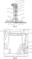
- An enlarged representation of part of the base 10 of the insert 4 is shown in Figure 4 .
- an end 32 of one of second external ribs 14 is shown, forming a kind of fork with three prongs 33.
- the general shape of the insert, with in particular first external ribs 9, second external ribs 14, end 32 with prongs 33, shape of base 10, is chosen so as to provide a rigid wing, even when the thickness of the foam 5 is about equal to 5 mm.
- the shape of the insert may be different without departing from the scope of the invention.
- the foam 5, shown in Figure 5 comprises a polypropylene foam with closed cells.
- Foam 5 has a density of about 200 kg/m 3 .
- the foam 5 is moulded by injection over the insert 4, in such a manner as to have everywhere a thickness equal or greater than 5 mm.
- the base 10 and the open end 8 of the hollow tube 7 are visible in figure 3 , as these parts of the insert 4 are not covered by the foam 5.
- the shape of foam 5 is similar to the end global shape of the underwater floating device and forms a wing.
- the external shape of the foam 5 or of the underwater floating device 1 may be different without departing from the scope of the invention.
- the foam 5 and the insert 4 stick to each other, without any adhesive.
- the lines 13 are in the example marks of the injection.
- An opening 30 is represented in Figure 5 .
- Such opening 30 is foreseen so as to allow the fastening of the underwater floating device 1 to an arm of a body of the navigation control device 2.
- the outer skin 6 is moulded by injection over the foam 5. This outer skin is shown in figure 4 .
- the outer skin 6 is made in polypropylene. It entirely covers foam 5 and is watertight. The outer skin 6 and the foam 5 stick to each other, without help of an adhesive.
- Such adhesion between two or three layers may be obtained without adding any adhesive, due in particular to the fact that the different components or layers of the underwater floating device are made of a thermoplastic material.
- the adhesion between at least two layers of the underwater floating device reinforce the global structure of the underwater floating device, eliminating any clearance between the concerned components. Furthermore, in case of damage of the outer skin, the adhesion between the layers prevents water from seeping into the underwater floating device.
- the opening 30 is covered by outer skin 6, as shown in Figure 6 on the rectangular place 34.
- the method for making the underwater floating device is the following.
- a mould for the insert is filled by injection with polypropylene, optionally comprising fiberglass.
- the insert 4 is then covered in another mould, by injection, with the foam 5 which is itself covered by injection with the outer skin 6.
- thermosetting material In this process, the temperature and pressure of injection of the skin have to be high so that there is a risk of melting the foam during injection of the skin and a risk of compressing the foam in its totality. Such risks are not encountered by thermosetting material.
- thermoplastic material on the foam is therefore optimized in order to center the foam in the mould, obviate the fusion of the foam, minimize the injection pressures so as to reduce deformations and limit the geometrical deformations linked to shrinkage.
- This injection may be realized in one or several steps due to the constraints of the device according to the invention.
- the underwater floating device is a wing of a navigation control device but it may be another submarine device without departing from the scope of the invention.
Abstract
- an insert (4) comprising a thermoplastic material,
- a foam (5) of a thermoplastic material, at least partly covering the insert (4),
- an outer skin (6) comprising a thermoplastic material and configured for being in contact with water during use.
Description
- The present invention relates to floating devices, in particular submarine or underwater floating devices. Such floating devices may be used in a marine environment, for example in the field of the acquisition of seismic data, oil or gas prospecting industry, marine research or offshore production.
- Such floating devices may consist in wings present in a navigation control device, also called « bird », for controlling the position of an instrumented cable towed in water, such as a marine seismic streamer, and/or the relative position of cables in a towed instrumented cable network of streamers.
- Underwater floating devices are supposed to, simultaneously, float, be able to resist to high pressures due to the depth at which they are used and be able to resist mechanical loads.
- Consequently, such devices must have an efficient density and an efficient mechanical structure in order to withstand pressure and mechanical loads during use.
- The floating devices are also supposed to be watertight. In case of damage, they should not be filled entirely with water.
- Techniques of seismic data acquisition usually require to tow streamers at depths comprised between 5 meters and 15 meters.
- New techniques of seismic data acquisition require now to tow streamers at depths that can reach 80 to 120 meters. Thus, during operations, the floating devices are therefore supposed to resist to pressures possibly reaching 1,2 MPa, i.e. until 12 bars.
- It is known to make a floating device with a foam core of PVC (Polyvinyl chloride) covered with a skin of polyurethane low pressure. The foam is machined, which is expensive. The skin is in a thermosetting material, which is not recyclable.
- Another device of this type is disclosed in
US 2010/037402 , which device comprises a hollow skeleton and a seal. This device has the drawback of being hollow, so that in case of damage, it will get full of water, and would not thus be able to float anymore. Another drawback of this known device is that it comprises a lot of fiberglass which create deformations of the panels which makes it difficult to assemble. - Another known floating device comprises an epoxy resin foam and a skin made of an epoxy resin or a polyurethane. Such thermosetting device is not recyclable, is expensive and fragile in case of collision. Furthermore, the epoxy resin foam comprises open cells which fill up with water in case of damage of the device.
- Another known device comprises a foam of polyurethane which forms a skin when in contact with water. Such device is not recyclable and is expensive.
- The invention aims at providing a floating device which remedies to the deficiencies of known devices.
- In particular, an objective of the invention is to provide a floating device having density and floating properties enabling it to be used under water when pressure reaches high pressures such as pressures comprised between 0,8 to 1,2 MPa.
- Another objective of the invention is to provide a floating device that is not expensive, that is environment-friendly by being recyclable.
- Another objective of the invention is to provide a floating device that does not fill up with water in case of damage, for example when a collision occurs.
- The invention satisfies all or part of these objectives with an underwater floating device, for example an underwater floating device having an elastic limit in compression equal to about 1,2 MPa, the underwater floating device comprising :
- an insert comprising a thermoplastic material,
- a foam made of a thermoplastic material, at least partly covering the insert,
- an outer skin comprising a thermoplastic material and configured for being in contact with water during use.
- Thanks to the invention, the underwater floating device has the required technical features, being simultaneously watertight, thanks to the outer skin, floating and light thanks to the foam, and pressure resistant thanks to the combination of the components forming the underwater floating device. Furthermore, the underwater floating device can be recycled and is not expensive to produce, thanks to the thermoplastic material forming the different components of the device.
- For making the invention, the inventors have gone beyond presumption that it was not possible to work with thermoplastic materials in such application, and in particular to use several thermoplastic components.
- For thermoplastic materials indeed, the thickness of the material has to be low and constant, during manufacturing. The reason is that the greater the thickness is, the more important the phenomena of shrinkage of the material are, which is not the case of thermosetting material.
- The inventors thus found that the presence of an insert enables the use of a thermoplastic material.
- The shape of the insert helps compensate for places where the thickness of the foam is too low, therefore rigidifies the underwater floating device.
- Variations of thickness of the skin may also help compensate for places where there is a too low thickness of the foam.
- Furthermore, the inventors have gone beyond another presumption that it is not possible to arrange a foam of a thermoplastic material such as the skin on another thermoplastic material such as the foam. The reason is that the temperature and pressure of injection of the skin have to be high so that there is a risk of melting the foam during injection of the skin and a risk of compressing the foam in its totality. Such risks are not encountered by thermosetting material.
- The thermoplastic material of the insert, of the foam and of the skin may be based on a unique thermoplastic material, for example polypropylene.
- An advantage of such material is that it can be easily found on the market.
- This feature helps recycling the underwater floating device, as there is a unique material constituting the three components or layers of the underwater floating device.
- The device may have a global density in the range 50 kg/m3 to 750 kg/m3, for example in the range 150 kg/m3 to 500 kg/m3, for example equal to about 250 kg/m3 .
- Such a feature improves the buoyancy of the device.
- The insert and/or the foam and/or the skin may be shaped by injection moulding. This may facilitate the manufacturing of the underwater floating device.
- The foam may have a density in the
range 30 to 700 kg/m3, for example in the range 100 to 500 kg/m3, for example equal to about 200 kg/m3. Such a density improves the buoyancy, the foam being relatively light. - In a particular embodiment, the insert comprises fiberglass in a proportion between 0% to 60 %, for example between 5% and 40 %. Fiberglass enables to reinforce the structure of the insert. The presence of fiberglass requires to separate fiberglass from the rest of the device before recycling.
- The insert and the foam may stick to each other. The foam and the skin may stick to each other. Such adhesion between two or three layers may be obtained without adding any adhesive, due in particular to the fact that the different components or layers of the underwater floating device are made of a thermoplastic material. The adhesion between at least two layers of the underwater floating device reinforce the global structure of the underwater floating device, eliminating any clearance between the concerned components. Furthermore, in case of damage of the outer skin, the adhesion between the layers prevents water from seeping into the underwater floating device.
- The foam may comprise closed cells. The fact that the foam comprises closed cells advantageously limits the quantity of water that could saturate the foam in case of damage of the outer skin of the underwater floating device.
- In a preferred embodiment, the skin is watertight.
- The underwater floating device may be chosen in the group consisting of:
- a wing of a navigation control device, also called « bird »,
- a wing of an autonomous underwater vehicle,
- a wing of a glider.
- Another obj ect of the invention relates to a navigation control device comprising an underwater floating device as described above.
- The accompanying drawings, which are incorporated in and constitute a part of the specification, illustrate one or more embodiments and, together with the description, explain these embodiments. In the drawings:
-
Figure 1 is a schematic representation of part of a seismic streamer including a navigation control device comprising an underwater floating device according to the invention ; -
Figure 2 is a schematic representation of a network of streamers towed by a vessel, including several navigation control devices as the one ofFigure 1 ; -
Figure 3 is a schematic representation in perspective of an example of an insert, part of the underwater floating device according to the invention ; -
Figure 4 is a schematic enlarged representation of part IV of the insert ofFigure 3 ; -
Figure 5 is a schematic representation in perspective of an example of a foam, part of the underwater floating device according to the invention ; and -
Figure 6 is a schematic representation in perspective of an example of an outer skin, part of the underwater floating device according to the invention. - The underwater floating device according to the invention may be a wing of a navigation control device, also called « bird », a wing of an autonomous underwater vehicle or a wing of a glider or any other suitable marine device.
- In the exemplary embodiment shown in the figures, the underwater floating
device 1 is a wing of anavigation control device 2, or « bird », as can be seen infigure 1 . Suchnavigation control device 2 comprises three wings in this example and is part of aseismic streamer 3. Theseismic streamer 3 is partly shown infigure 1 and comprises a plurality ofsensors 20, also called hydrophones, andtransducers 22, among which one is shown inFigure 1 . - The
seismic streamer 3 is part of a network of seismic streamers, shown inFigure 2 , that is towed by avessel 21, on which is located a centralized system (not shown) comprising a navigation system and a node manager system. - In the exemplary embodiment, the role of the
navigation control device 2 is the acoustic positioning of seismic streamers and sources and the control of seismic streamers. It includes three sub-systems: - a streamer depth and steering controller,
- acoustic transceivers, and
- an advanced redundant telemetry sub-system.
- The streamers network is suitable for being towed at a level under the sealevel of about 100 meters, so that the mechanical loads and water pressure are considerable.
- The underwater floating
device 1, according to the invention, has, in this embodiment, an elastic limit in compression up to about 1,2 MPa, and comprises three components or layers : - an
insert 4 comprising a thermoplastic material, - a
foam 5 of a thermoplastic material, at least partly covering the insert, - an
outer skin 6 comprising a thermoplastic material and configured for being in contact with water during use. - For making the invention, the inventors have gone beyond presumption that it was not possible to work with thermoplastic materials in such application, and in particular to use several thermoplastic components.
- For thermoplastic materials indeed, the thickness of the material has to be low and constant, during manufacturing. The reason is that the greater the thickness is, the more important the phenomena of shrinkage of the material are, which is not the case of thermosetting material.
- The inventors thus found that the presence of an insert enables the use of a thermoplastic material.
- The shape of the insert helps compensate for places where the thickness of the foam is too low, therefore rigidifies the underwater floating device.
- Variations of thickness of the skin may also help compensate for places where there is a too low thickness of the foam.
- The global density of the underwater floating
device 1 itself is between 50 to 750 kg/m3, in this example equal to about 250 kg/m3. - The
insert 4 is shown aside infigure 3 . In this example, theinsert 4 is made by injection of a thermoplastic material consisting of polypropylene in the embodiment. It comprises a small proportion of fiberglass so as to reinforce its structure. Theinsert 4 comprises ahollow tube 7 extending according to a longitudinal axis X, opened at oneopen end 8, and having a circular cross-section. Thehollow tube 7 allows the fastening of the wing to thenavigation control device 2 in this example. Thehollow tube 7 has anotherclosed end 11 topped by anupper end 12 of theinsert 4, whose width is greater than the diameter of thehollow tube 7. - The
insert 4 also comprises a base 10 extending around theopen end 8, perpendicularly to the axis X of the hollow tube, in a non-symetrical manner. Theinsert 4 comprises firstexternal ribs 9 that are substantially perpendicular to axis X and secondexternal ribs 14 that are substantially parallel to axis X and connect theupper end 12 and thebase 10. An enlarged representation of part of thebase 10 of theinsert 4 is shown inFigure 4 . In this Figure, anend 32 of one of secondexternal ribs 14 is shown, forming a kind of fork with three prongs 33.The general shape of the insert, with in particular firstexternal ribs 9, secondexternal ribs 14, end 32 withprongs 33, shape ofbase 10, is chosen so as to provide a rigid wing, even when the thickness of thefoam 5 is about equal to 5 mm. - The shape of the insert may be different without departing from the scope of the invention.
- The
foam 5, shown inFigure 5 , comprises a polypropylene foam with closed cells.Foam 5 has a density of about 200 kg/m3. Thefoam 5 is moulded by injection over theinsert 4, in such a manner as to have everywhere a thickness equal or greater than 5 mm. Thebase 10 and theopen end 8 of thehollow tube 7 are visible infigure 3 , as these parts of theinsert 4 are not covered by thefoam 5. - The shape of
foam 5 is similar to the end global shape of the underwater floating device and forms a wing. The external shape of thefoam 5 or of the underwater floatingdevice 1 may be different without departing from the scope of the invention. - In this example, the
foam 5 and theinsert 4 stick to each other, without any adhesive. Thelines 13 are in the example marks of the injection. - An
opening 30 is represented inFigure 5 .Such opening 30 is foreseen so as to allow the fastening of the underwater floatingdevice 1 to an arm of a body of thenavigation control device 2. - The
outer skin 6 is moulded by injection over thefoam 5. This outer skin is shown infigure 4 . Theouter skin 6 is made in polypropylene. It entirely coversfoam 5 and is watertight. Theouter skin 6 and thefoam 5 stick to each other, without help of an adhesive. - Such adhesion between two or three layers may be obtained without adding any adhesive, due in particular to the fact that the different components or layers of the underwater floating device are made of a thermoplastic material. The adhesion between at least two layers of the underwater floating device reinforce the global structure of the underwater floating device, eliminating any clearance between the concerned components. Furthermore, in case of damage of the outer skin, the adhesion between the layers prevents water from seeping into the underwater floating device.
- The stripes of two different colors visible in
figure 6 are limited by thelines 13 of thefoam 5 and are made during the injection process. They have no technical function in the invention but a visual effect. - The
opening 30 is covered byouter skin 6, as shown inFigure 6 on therectangular place 34. - The method for making the underwater floating device is the following. A mould for the insert is filled by injection with polypropylene, optionally comprising fiberglass. The
insert 4 is then covered in another mould, by injection, with thefoam 5 which is itself covered by injection with theouter skin 6. - In this process, the temperature and pressure of injection of the skin have to be high so that there is a risk of melting the foam during injection of the skin and a risk of compressing the foam in its totality. Such risks are not encountered by thermosetting material.
- The injection of a thermoplastic material on the foam is therefore optimized in order to center the foam in the mould, obviate the fusion of the foam, minimize the injection pressures so as to reduce deformations and limit the geometrical deformations linked to shrinkage. This injection may be realized in one or several steps due to the constraints of the device according to the invention.
- In the disclosed embodiment, the underwater floating device is a wing of a navigation control device but it may be another submarine device without departing from the scope of the invention.
- The patentable scope of the subject matter is defined by the claims, and may include other examples that occur to those skilled in the art. Such other examples are intended to be within the scope of the claims.
- The expression «comprising a» should be interpreted as being synonymous of the expression « comprising at least one », unless the contrary is specified.
- The ranges should be interpreted as including the limits, unless the contrary is specified.
Claims (14)
- An underwater floating device (1) characterized in that it comprises :- an insert (4) comprising a thermoplastic material,- a foam (5) of a thermoplastic material, at least partly covering the insert (4),- an outer skin (6) comprising a thermoplastic material and configured for being in contact with water during use.
- Underwater floating device (1) according to claim 1, in which the thermoplastic material of the insert (4), of the foam (5) and of the skin (6) is based on a unique thermoplastic material.
- Underwater floating device (1) according to claim 2, in which said thermoplastic material is polypropylene.
- Underwater floating device according to any of the preceding claims, in which the device has a global density in the range 50 kg/m3 to 250 kg/m3.
- Underwater floating device (1) according to any of the preceding claims, in which the insert (4) and/or the foam (5) and/or the skin (6) are shaped by injection moulding.
- Underwater floating device (1) according to any of the preceding claims, in which the foam (5) has a density in the range 50 to 700 kg/m3.
- Underwater floating device (1) according to any of the preceding claims, in which the insert (4) comprises fiberglass in a proportion between 0% to 60%.
- Underwater floating device (1) according to any of the preceding claims, in which the insert (4) and the foam (5) stick to each other.
- Underwater floating device (1) according to any of the preceding claims, in which the foam (5) and the skin (6) stick to each other.
- Underwater floating device (1) according to any of the preceding claims, in which the foam (5) comprises closed cells.
- Underwater floating device (1) according to any of the preceding claims, in which the skin is watertight.
- Underwater floating device (1) according to any of the preceding claims, wherein an elastic limit in compression of the underwater floating device is equal to about 1,2 MPa.
- Underwater floating device (1) according to any of the preceding claims, said device being chosen in the group consisting of :- a wing of a navigation control device,- a wing of an autonomous underwater vehicle,- a wing of a glider.
- A navigation control device (2) comprising at least one underwater floating device according to any of claims 1 to 13.
Priority Applications (8)
| Application Number | Priority Date | Filing Date | Title |
|---|---|---|---|
| EP11306558.5A EP2597024B1 (en) | 2011-11-25 | 2011-11-25 | Underwater floating device and method of manufacturing thereof |
| CA2795646A CA2795646C (en) | 2011-11-25 | 2012-11-09 | An underwater floating device |
| RU2012148594/11A RU2592956C2 (en) | 2011-11-25 | 2012-11-15 | Underwater floating device |
| MX2012013566A MX2012013566A (en) | 2011-11-25 | 2012-11-22 | Underwater floating device. |
| CN201210480263.8A CN103129414B (en) | 2011-11-25 | 2012-11-23 | Flotation gear under water |
| BR102012029934-8A BR102012029934B1 (en) | 2011-11-25 | 2012-11-23 | underwater flotation device navigation control device |
| US13/684,434 US8893637B2 (en) | 2011-11-25 | 2012-11-23 | Underwater floating device |
| US14/519,892 US9394042B2 (en) | 2011-11-25 | 2014-10-21 | Underwater floating device |
Applications Claiming Priority (1)
| Application Number | Priority Date | Filing Date | Title |
|---|---|---|---|
| EP11306558.5A EP2597024B1 (en) | 2011-11-25 | 2011-11-25 | Underwater floating device and method of manufacturing thereof |
Publications (2)
| Publication Number | Publication Date |
|---|---|
| EP2597024A1 true EP2597024A1 (en) | 2013-05-29 |
| EP2597024B1 EP2597024B1 (en) | 2014-07-23 |
Family
ID=45872765
Family Applications (1)
| Application Number | Title | Priority Date | Filing Date |
|---|---|---|---|
| EP11306558.5A Active EP2597024B1 (en) | 2011-11-25 | 2011-11-25 | Underwater floating device and method of manufacturing thereof |
Country Status (7)
| Country | Link |
|---|---|
| US (2) | US8893637B2 (en) |
| EP (1) | EP2597024B1 (en) |
| CN (1) | CN103129414B (en) |
| BR (1) | BR102012029934B1 (en) |
| CA (1) | CA2795646C (en) |
| MX (1) | MX2012013566A (en) |
| RU (1) | RU2592956C2 (en) |
Families Citing this family (11)
| Publication number | Priority date | Publication date | Assignee | Title |
|---|---|---|---|---|
| US9632195B2 (en) | 2011-10-28 | 2017-04-25 | Gx Technology Canada Ltd. | Steerable fairing string |
| EP2597024B1 (en) * | 2011-11-25 | 2014-07-23 | Sercel | Underwater floating device and method of manufacturing thereof |
| WO2016086293A1 (en) * | 2014-12-05 | 2016-06-09 | Global Dynamics Incorporated | Segmented-foil divertor |
| AU2016337528B2 (en) | 2015-10-15 | 2020-11-12 | Ion Geophysical Corporation | Dynamically controlled foil systems and methods |
| MX2018009866A (en) | 2016-02-16 | 2018-11-09 | Gx Tech Canada Ltd | Ribbon foil depressor. |
| CN108068257B (en) * | 2016-11-14 | 2019-07-23 | 中天科技海缆有限公司 | Floating body and its forming method |
| CN106628002A (en) * | 2016-12-06 | 2017-05-10 | 中国船舶重工集团公司第七0研究所 | Position-Indicating float towed in water |
| WO2019222809A1 (en) | 2018-05-23 | 2019-11-28 | Woodside Energy Technologies Pty Ltd | An autonomous data acquisition system and method |
| CN113382922A (en) | 2018-10-09 | 2021-09-10 | Gx技术加拿大有限公司 | Modular airfoil system for towed marine array |
| US11465549B2 (en) * | 2019-09-18 | 2022-10-11 | Usa Products Group | Floating load tension assembly with high visibility |
| RU2741140C1 (en) * | 2020-06-19 | 2021-01-22 | Александр Ливиевич Ураков | Polar submarine |
Citations (6)
| Publication number | Priority date | Publication date | Assignee | Title |
|---|---|---|---|---|
| DE3438518A1 (en) * | 1984-10-20 | 1986-04-24 | Binder, geb. Möschl, Birgit, 7100 Heilbronn | Fin for a watercraft |
| FR2800348A1 (en) * | 1999-10-27 | 2001-05-04 | Francois Lucas | Sail boat with keel suspended from hull by ball joint which allows its longitudinal pivoting |
| US6516736B1 (en) * | 2000-11-28 | 2003-02-11 | Genmar Ip Llc | Pontoon watercraft and method for making same |
| WO2006061687A1 (en) * | 2004-12-10 | 2006-06-15 | Bamba International (Canada) Ltd. | Sports board |
| US20080146102A1 (en) * | 2005-06-27 | 2008-06-19 | Wah Kan Cheung | Thermoformed sports board |
| US20100037402A1 (en) | 2002-05-15 | 2010-02-18 | Bon Kwon Koo | Method of controlling motor-driven washing machine and control system for the same |
Family Cites Families (10)
| Publication number | Priority date | Publication date | Assignee | Title |
|---|---|---|---|---|
| DE2844766C2 (en) * | 1978-10-13 | 1981-02-12 | Klaus Dipl.-Ing. 8032 Graefelfing Enzmann | Fin for watercraft |
| HU202782B (en) * | 1984-09-12 | 1991-04-29 | Muanyagipari Kutato Intezet | Flexible technical hose of foam insert and method for producing same |
| NO860780L (en) * | 1985-03-05 | 1986-09-08 | Exxon Production Research Co | N ESTABLISHMENT OF MARINE SEISMIC SOURCES. |
| US4764137A (en) * | 1986-11-13 | 1988-08-16 | Frank Schulte | Floatable dredge hose |
| SU1728826A1 (en) * | 1990-04-04 | 1992-04-23 | Научно-исследовательский институт морской геофизики Производственного объединения "Союзморгео" | Hydrodynamic stabilizer of travel of towed receiving systems |
| JP3342493B2 (en) * | 1994-07-02 | 2002-11-11 | フェニックス アクチエンゲゼルシャフト | Float for floating pipe |
| US5867451A (en) * | 1997-01-17 | 1999-02-02 | Input/Output, Inc. | Solid marine seismic cable assembly |
| EP1506433B1 (en) * | 2002-05-23 | 2009-12-30 | ION Geophysical Corporation | Gps-based underwater cable positioning system |
| US7092315B2 (en) * | 2004-05-27 | 2006-08-15 | Input/Output, Inc. | Device for laterally steering streamer cables |
| EP2597024B1 (en) * | 2011-11-25 | 2014-07-23 | Sercel | Underwater floating device and method of manufacturing thereof |
-
2011
- 2011-11-25 EP EP11306558.5A patent/EP2597024B1/en active Active
-
2012
- 2012-11-09 CA CA2795646A patent/CA2795646C/en active Active
- 2012-11-15 RU RU2012148594/11A patent/RU2592956C2/en not_active IP Right Cessation
- 2012-11-22 MX MX2012013566A patent/MX2012013566A/en active IP Right Grant
- 2012-11-23 CN CN201210480263.8A patent/CN103129414B/en active Active
- 2012-11-23 US US13/684,434 patent/US8893637B2/en active Active
- 2012-11-23 BR BR102012029934-8A patent/BR102012029934B1/en active IP Right Grant
-
2014
- 2014-10-21 US US14/519,892 patent/US9394042B2/en active Active
Patent Citations (6)
| Publication number | Priority date | Publication date | Assignee | Title |
|---|---|---|---|---|
| DE3438518A1 (en) * | 1984-10-20 | 1986-04-24 | Binder, geb. Möschl, Birgit, 7100 Heilbronn | Fin for a watercraft |
| FR2800348A1 (en) * | 1999-10-27 | 2001-05-04 | Francois Lucas | Sail boat with keel suspended from hull by ball joint which allows its longitudinal pivoting |
| US6516736B1 (en) * | 2000-11-28 | 2003-02-11 | Genmar Ip Llc | Pontoon watercraft and method for making same |
| US20100037402A1 (en) | 2002-05-15 | 2010-02-18 | Bon Kwon Koo | Method of controlling motor-driven washing machine and control system for the same |
| WO2006061687A1 (en) * | 2004-12-10 | 2006-06-15 | Bamba International (Canada) Ltd. | Sports board |
| US20080146102A1 (en) * | 2005-06-27 | 2008-06-19 | Wah Kan Cheung | Thermoformed sports board |
Also Published As
| Publication number | Publication date |
|---|---|
| CA2795646A1 (en) | 2013-05-25 |
| BR102012029934A2 (en) | 2015-11-03 |
| US20150065000A1 (en) | 2015-03-05 |
| RU2592956C2 (en) | 2016-07-27 |
| US8893637B2 (en) | 2014-11-25 |
| EP2597024B1 (en) | 2014-07-23 |
| US9394042B2 (en) | 2016-07-19 |
| CN103129414A (en) | 2013-06-05 |
| BR102012029934B1 (en) | 2020-11-03 |
| RU2012148594A (en) | 2014-05-20 |
| US20130137321A1 (en) | 2013-05-30 |
| MX2012013566A (en) | 2014-03-06 |
| CA2795646C (en) | 2020-07-28 |
| CN103129414B (en) | 2016-12-21 |
Similar Documents
| Publication | Publication Date | Title |
|---|---|---|
| EP2597024B1 (en) | Underwater floating device and method of manufacturing thereof | |
| CN108116628B (en) | Self-propelled ocean platform capable of being freely assembled | |
| CN101738635A (en) | Seismic streamer formed of sections comprising a main sheath covered with an external sheath formed using a thermoplastic material loaded with a biocide material | |
| CN202110293U (en) | Single compartment ball submarine electric field instrument | |
| CN106965905B (en) | Marine acoustics measures buoyage | |
| CN106828833B (en) | A kind of hidden indirect communication device in deep-sea | |
| CN207658000U (en) | Deep-sea pressure-resistant floating ball | |
| CN109572937A (en) | A kind of deep-sea control buoy | |
| CN204270725U (en) | A kind of intelligent extra large cable | |
| CN114604400B (en) | Underwater glider with sinking detection function | |
| CN201932351U (en) | Underwater observation platform applying floating material | |
| CN102568464B (en) | Underwater transducer for deepwater | |
| US9279524B2 (en) | Pipe for drawing up cold water for a marine thermal energy plant | |
| US11442190B2 (en) | Autonomous marine survey nodes | |
| CN108519620B (en) | Submarine seismic detection aircraft capable of being automatically distributed and recovered | |
| CN105275014A (en) | Butt joint installing device for underwater suspension tunnel pipe sections | |
| CN201616642U (en) | Submarine cable protection jacket structure | |
| CN114114423B (en) | Marine seismic streamer equipment and method capable of providing tension and water stack information | |
| EP4141863A1 (en) | A module for a towable sonar apparatus | |
| KR20170056924A (en) | The manufacture method of a green float growthing uplipting force and float using the method | |
| Sun et al. | An Acoustic Profiling Buoy used for Deepsea Noise Observation | |
| CN104980715B (en) | A kind of application method of the underwater automatic observation device of unmanned submersible | |
| EP3051317B1 (en) | An electronic unit for a streamer | |
| US20140269172A1 (en) | Anti-fouling seismic streamer | |
| KR20150057225A (en) | Oval shape float or cone shape float and manufacturing method thereof |
Legal Events
| Date | Code | Title | Description |
|---|---|---|---|
| PUAI | Public reference made under article 153(3) epc to a published international application that has entered the european phase |
Free format text: ORIGINAL CODE: 0009012 |
|
| AK | Designated contracting states |
Kind code of ref document: A1 Designated state(s): AL AT BE BG CH CY CZ DE DK EE ES FI FR GB GR HR HU IE IS IT LI LT LU LV MC MK MT NL NO PL PT RO RS SE SI SK SM TR |
|
| AX | Request for extension of the european patent |
Extension state: BA ME |
|
| 17P | Request for examination filed |
Effective date: 20130530 |
|
| RBV | Designated contracting states (corrected) |
Designated state(s): AL AT BE BG CH CY CZ DE DK EE ES FI FR GB GR HR HU IE IS IT LI LT LU LV MC MK MT NL NO PL PT RO RS SE SI SK SM TR |
|
| 17Q | First examination report despatched |
Effective date: 20130808 |
|
| GRAP | Despatch of communication of intention to grant a patent |
Free format text: ORIGINAL CODE: EPIDOSNIGR1 |
|
| INTG | Intention to grant announced |
Effective date: 20140313 |
|
| RIN1 | Information on inventor provided before grant (corrected) |
Inventor name: VIGNAUX, JEAN-JACQUES Inventor name: ROGER, THIERRY Inventor name: AUGOR, CHRISTOPHE |
|
| GRAS | Grant fee paid |
Free format text: ORIGINAL CODE: EPIDOSNIGR3 |
|
| GRAA | (expected) grant |
Free format text: ORIGINAL CODE: 0009210 |
|
| AK | Designated contracting states |
Kind code of ref document: B1 Designated state(s): AL AT BE BG CH CY CZ DE DK EE ES FI FR GB GR HR HU IE IS IT LI LT LU LV MC MK MT NL NO PL PT RO RS SE SI SK SM TR |
|
| REG | Reference to a national code |
Ref country code: GB Ref legal event code: FG4D |
|
| REG | Reference to a national code |
Ref country code: CH Ref legal event code: EP |
|
| REG | Reference to a national code |
Ref country code: IE Ref legal event code: FG4D |
|
| REG | Reference to a national code |
Ref country code: AT Ref legal event code: REF Ref document number: 678692 Country of ref document: AT Kind code of ref document: T Effective date: 20140815 |
|
| REG | Reference to a national code |
Ref country code: DE Ref legal event code: R096 Ref document number: 602011008554 Country of ref document: DE Effective date: 20140904 |
|
| REG | Reference to a national code |
Ref country code: NO Ref legal event code: T2 Effective date: 20140723 |
|
| REG | Reference to a national code |
Ref country code: AT Ref legal event code: MK05 Ref document number: 678692 Country of ref document: AT Kind code of ref document: T Effective date: 20140723 |
|
| REG | Reference to a national code |
Ref country code: NL Ref legal event code: VDEP Effective date: 20140723 |
|
| REG | Reference to a national code |
Ref country code: LT Ref legal event code: MG4D |
|
| PG25 | Lapsed in a contracting state [announced via postgrant information from national office to epo] |
Ref country code: FI Free format text: LAPSE BECAUSE OF FAILURE TO SUBMIT A TRANSLATION OF THE DESCRIPTION OR TO PAY THE FEE WITHIN THE PRESCRIBED TIME-LIMIT Effective date: 20140723 Ref country code: GR Free format text: LAPSE BECAUSE OF FAILURE TO SUBMIT A TRANSLATION OF THE DESCRIPTION OR TO PAY THE FEE WITHIN THE PRESCRIBED TIME-LIMIT Effective date: 20141024 Ref country code: ES Free format text: LAPSE BECAUSE OF FAILURE TO SUBMIT A TRANSLATION OF THE DESCRIPTION OR TO PAY THE FEE WITHIN THE PRESCRIBED TIME-LIMIT Effective date: 20140723 Ref country code: BG Free format text: LAPSE BECAUSE OF FAILURE TO SUBMIT A TRANSLATION OF THE DESCRIPTION OR TO PAY THE FEE WITHIN THE PRESCRIBED TIME-LIMIT Effective date: 20141023 Ref country code: LT Free format text: LAPSE BECAUSE OF FAILURE TO SUBMIT A TRANSLATION OF THE DESCRIPTION OR TO PAY THE FEE WITHIN THE PRESCRIBED TIME-LIMIT Effective date: 20140723 Ref country code: PT Free format text: LAPSE BECAUSE OF FAILURE TO SUBMIT A TRANSLATION OF THE DESCRIPTION OR TO PAY THE FEE WITHIN THE PRESCRIBED TIME-LIMIT Effective date: 20141124 Ref country code: SE Free format text: LAPSE BECAUSE OF FAILURE TO SUBMIT A TRANSLATION OF THE DESCRIPTION OR TO PAY THE FEE WITHIN THE PRESCRIBED TIME-LIMIT Effective date: 20140723 |
|
| PG25 | Lapsed in a contracting state [announced via postgrant information from national office to epo] |
Ref country code: AT Free format text: LAPSE BECAUSE OF FAILURE TO SUBMIT A TRANSLATION OF THE DESCRIPTION OR TO PAY THE FEE WITHIN THE PRESCRIBED TIME-LIMIT Effective date: 20140723 Ref country code: PL Free format text: LAPSE BECAUSE OF FAILURE TO SUBMIT A TRANSLATION OF THE DESCRIPTION OR TO PAY THE FEE WITHIN THE PRESCRIBED TIME-LIMIT Effective date: 20140723 Ref country code: NL Free format text: LAPSE BECAUSE OF FAILURE TO SUBMIT A TRANSLATION OF THE DESCRIPTION OR TO PAY THE FEE WITHIN THE PRESCRIBED TIME-LIMIT Effective date: 20140723 Ref country code: IS Free format text: LAPSE BECAUSE OF FAILURE TO SUBMIT A TRANSLATION OF THE DESCRIPTION OR TO PAY THE FEE WITHIN THE PRESCRIBED TIME-LIMIT Effective date: 20141123 Ref country code: HR Free format text: LAPSE BECAUSE OF FAILURE TO SUBMIT A TRANSLATION OF THE DESCRIPTION OR TO PAY THE FEE WITHIN THE PRESCRIBED TIME-LIMIT Effective date: 20140723 Ref country code: CY Free format text: LAPSE BECAUSE OF FAILURE TO SUBMIT A TRANSLATION OF THE DESCRIPTION OR TO PAY THE FEE WITHIN THE PRESCRIBED TIME-LIMIT Effective date: 20140723 Ref country code: LV Free format text: LAPSE BECAUSE OF FAILURE TO SUBMIT A TRANSLATION OF THE DESCRIPTION OR TO PAY THE FEE WITHIN THE PRESCRIBED TIME-LIMIT Effective date: 20140723 Ref country code: RS Free format text: LAPSE BECAUSE OF FAILURE TO SUBMIT A TRANSLATION OF THE DESCRIPTION OR TO PAY THE FEE WITHIN THE PRESCRIBED TIME-LIMIT Effective date: 20140723 |
|
| REG | Reference to a national code |
Ref country code: DE Ref legal event code: R097 Ref document number: 602011008554 Country of ref document: DE |
|
| PG25 | Lapsed in a contracting state [announced via postgrant information from national office to epo] |
Ref country code: IT Free format text: LAPSE BECAUSE OF FAILURE TO SUBMIT A TRANSLATION OF THE DESCRIPTION OR TO PAY THE FEE WITHIN THE PRESCRIBED TIME-LIMIT Effective date: 20140723 Ref country code: CZ Free format text: LAPSE BECAUSE OF FAILURE TO SUBMIT A TRANSLATION OF THE DESCRIPTION OR TO PAY THE FEE WITHIN THE PRESCRIBED TIME-LIMIT Effective date: 20140723 Ref country code: EE Free format text: LAPSE BECAUSE OF FAILURE TO SUBMIT A TRANSLATION OF THE DESCRIPTION OR TO PAY THE FEE WITHIN THE PRESCRIBED TIME-LIMIT Effective date: 20140723 Ref country code: DK Free format text: LAPSE BECAUSE OF FAILURE TO SUBMIT A TRANSLATION OF THE DESCRIPTION OR TO PAY THE FEE WITHIN THE PRESCRIBED TIME-LIMIT Effective date: 20140723 Ref country code: RO Free format text: LAPSE BECAUSE OF FAILURE TO SUBMIT A TRANSLATION OF THE DESCRIPTION OR TO PAY THE FEE WITHIN THE PRESCRIBED TIME-LIMIT Effective date: 20140723 Ref country code: SK Free format text: LAPSE BECAUSE OF FAILURE TO SUBMIT A TRANSLATION OF THE DESCRIPTION OR TO PAY THE FEE WITHIN THE PRESCRIBED TIME-LIMIT Effective date: 20140723 |
|
| PLBE | No opposition filed within time limit |
Free format text: ORIGINAL CODE: 0009261 |
|
| STAA | Information on the status of an ep patent application or granted ep patent |
Free format text: STATUS: NO OPPOSITION FILED WITHIN TIME LIMIT |
|
| REG | Reference to a national code |
Ref country code: DE Ref legal event code: R119 Ref document number: 602011008554 Country of ref document: DE |
|
| PG25 | Lapsed in a contracting state [announced via postgrant information from national office to epo] |
Ref country code: BE Free format text: LAPSE BECAUSE OF NON-PAYMENT OF DUE FEES Effective date: 20141130 Ref country code: LU Free format text: LAPSE BECAUSE OF FAILURE TO SUBMIT A TRANSLATION OF THE DESCRIPTION OR TO PAY THE FEE WITHIN THE PRESCRIBED TIME-LIMIT Effective date: 20141125 Ref country code: MC Free format text: LAPSE BECAUSE OF FAILURE TO SUBMIT A TRANSLATION OF THE DESCRIPTION OR TO PAY THE FEE WITHIN THE PRESCRIBED TIME-LIMIT Effective date: 20140723 |
|
| REG | Reference to a national code |
Ref country code: CH Ref legal event code: PL |
|
| 26N | No opposition filed |
Effective date: 20150424 |
|
| PG25 | Lapsed in a contracting state [announced via postgrant information from national office to epo] |
Ref country code: CH Free format text: LAPSE BECAUSE OF NON-PAYMENT OF DUE FEES Effective date: 20141130 Ref country code: LI Free format text: LAPSE BECAUSE OF NON-PAYMENT OF DUE FEES Effective date: 20141130 |
|
| REG | Reference to a national code |
Ref country code: IE Ref legal event code: MM4A |
|
| PG25 | Lapsed in a contracting state [announced via postgrant information from national office to epo] |
Ref country code: IE Free format text: LAPSE BECAUSE OF NON-PAYMENT OF DUE FEES Effective date: 20141125 Ref country code: DE Free format text: LAPSE BECAUSE OF NON-PAYMENT OF DUE FEES Effective date: 20150602 |
|
| REG | Reference to a national code |
Ref country code: FR Ref legal event code: PLFP Year of fee payment: 5 |
|
| PG25 | Lapsed in a contracting state [announced via postgrant information from national office to epo] |
Ref country code: SI Free format text: LAPSE BECAUSE OF FAILURE TO SUBMIT A TRANSLATION OF THE DESCRIPTION OR TO PAY THE FEE WITHIN THE PRESCRIBED TIME-LIMIT Effective date: 20140723 |
|
| PG25 | Lapsed in a contracting state [announced via postgrant information from national office to epo] |
Ref country code: SM Free format text: LAPSE BECAUSE OF FAILURE TO SUBMIT A TRANSLATION OF THE DESCRIPTION OR TO PAY THE FEE WITHIN THE PRESCRIBED TIME-LIMIT Effective date: 20140723 |
|
| PG25 | Lapsed in a contracting state [announced via postgrant information from national office to epo] |
Ref country code: BE Free format text: LAPSE BECAUSE OF FAILURE TO SUBMIT A TRANSLATION OF THE DESCRIPTION OR TO PAY THE FEE WITHIN THE PRESCRIBED TIME-LIMIT Effective date: 20140723 Ref country code: HU Free format text: LAPSE BECAUSE OF FAILURE TO SUBMIT A TRANSLATION OF THE DESCRIPTION OR TO PAY THE FEE WITHIN THE PRESCRIBED TIME-LIMIT; INVALID AB INITIO Effective date: 20111125 Ref country code: TR Free format text: LAPSE BECAUSE OF FAILURE TO SUBMIT A TRANSLATION OF THE DESCRIPTION OR TO PAY THE FEE WITHIN THE PRESCRIBED TIME-LIMIT Effective date: 20140723 Ref country code: MT Free format text: LAPSE BECAUSE OF FAILURE TO SUBMIT A TRANSLATION OF THE DESCRIPTION OR TO PAY THE FEE WITHIN THE PRESCRIBED TIME-LIMIT Effective date: 20140723 |
|
| REG | Reference to a national code |
Ref country code: FR Ref legal event code: PLFP Year of fee payment: 6 |
|
| REG | Reference to a national code |
Ref country code: FR Ref legal event code: PLFP Year of fee payment: 7 |
|
| PG25 | Lapsed in a contracting state [announced via postgrant information from national office to epo] |
Ref country code: MK Free format text: LAPSE BECAUSE OF FAILURE TO SUBMIT A TRANSLATION OF THE DESCRIPTION OR TO PAY THE FEE WITHIN THE PRESCRIBED TIME-LIMIT Effective date: 20140723 |
|
| PG25 | Lapsed in a contracting state [announced via postgrant information from national office to epo] |
Ref country code: AL Free format text: LAPSE BECAUSE OF FAILURE TO SUBMIT A TRANSLATION OF THE DESCRIPTION OR TO PAY THE FEE WITHIN THE PRESCRIBED TIME-LIMIT Effective date: 20140723 |
|
| PGFP | Annual fee paid to national office [announced via postgrant information from national office to epo] |
Ref country code: GB Payment date: 20231123 Year of fee payment: 13 |
|
| PGFP | Annual fee paid to national office [announced via postgrant information from national office to epo] |
Ref country code: NO Payment date: 20231124 Year of fee payment: 13 Ref country code: FR Payment date: 20231120 Year of fee payment: 13 |