EP2596984A1 - Reclining mechanism - Google Patents
Reclining mechanism Download PDFInfo
- Publication number
- EP2596984A1 EP2596984A1 EP12193667.8A EP12193667A EP2596984A1 EP 2596984 A1 EP2596984 A1 EP 2596984A1 EP 12193667 A EP12193667 A EP 12193667A EP 2596984 A1 EP2596984 A1 EP 2596984A1
- Authority
- EP
- European Patent Office
- Prior art keywords
- sun gear
- restriction
- wedge
- shaped space
- section
- Prior art date
- Legal status (The legal status is an assumption and is not a legal conclusion. Google has not performed a legal analysis and makes no representation as to the accuracy of the status listed.)
- Withdrawn
Links
- 230000002093 peripheral effect Effects 0.000 claims abstract description 50
- 230000008878 coupling Effects 0.000 description 12
- 238000010168 coupling process Methods 0.000 description 12
- 238000005859 coupling reaction Methods 0.000 description 12
- 238000003780 insertion Methods 0.000 description 10
- 230000037431 insertion Effects 0.000 description 10
- 238000006073 displacement reaction Methods 0.000 description 6
- 238000005452 bending Methods 0.000 description 4
- 230000007423 decrease Effects 0.000 description 3
- 238000012986 modification Methods 0.000 description 3
- 230000004048 modification Effects 0.000 description 3
- 230000000149 penetrating effect Effects 0.000 description 2
- 238000005096 rolling process Methods 0.000 description 2
- 230000000694 effects Effects 0.000 description 1
- 238000000034 method Methods 0.000 description 1
Images


Classifications
-
- F—MECHANICAL ENGINEERING; LIGHTING; HEATING; WEAPONS; BLASTING
- F16—ENGINEERING ELEMENTS AND UNITS; GENERAL MEASURES FOR PRODUCING AND MAINTAINING EFFECTIVE FUNCTIONING OF MACHINES OR INSTALLATIONS; THERMAL INSULATION IN GENERAL
- F16H—GEARING
- F16H35/00—Gearings or mechanisms with other special functional features
-
- B—PERFORMING OPERATIONS; TRANSPORTING
- B60—VEHICLES IN GENERAL
- B60N—SEATS SPECIALLY ADAPTED FOR VEHICLES; VEHICLE PASSENGER ACCOMMODATION NOT OTHERWISE PROVIDED FOR
- B60N2/00—Seats specially adapted for vehicles; Arrangement or mounting of seats in vehicles
- B60N2/02—Seats specially adapted for vehicles; Arrangement or mounting of seats in vehicles the seat or part thereof being movable, e.g. adjustable
- B60N2/04—Seats specially adapted for vehicles; Arrangement or mounting of seats in vehicles the seat or part thereof being movable, e.g. adjustable the whole seat being movable
- B60N2/16—Seats specially adapted for vehicles; Arrangement or mounting of seats in vehicles the seat or part thereof being movable, e.g. adjustable the whole seat being movable height-adjustable
- B60N2/1635—Seats specially adapted for vehicles; Arrangement or mounting of seats in vehicles the seat or part thereof being movable, e.g. adjustable the whole seat being movable height-adjustable characterised by the drive mechanism
- B60N2/1655—Cycloidal or planetary mechanism
-
- B—PERFORMING OPERATIONS; TRANSPORTING
- B60—VEHICLES IN GENERAL
- B60N—SEATS SPECIALLY ADAPTED FOR VEHICLES; VEHICLE PASSENGER ACCOMMODATION NOT OTHERWISE PROVIDED FOR
- B60N2/00—Seats specially adapted for vehicles; Arrangement or mounting of seats in vehicles
- B60N2/02—Seats specially adapted for vehicles; Arrangement or mounting of seats in vehicles the seat or part thereof being movable, e.g. adjustable
- B60N2/04—Seats specially adapted for vehicles; Arrangement or mounting of seats in vehicles the seat or part thereof being movable, e.g. adjustable the whole seat being movable
- B60N2/16—Seats specially adapted for vehicles; Arrangement or mounting of seats in vehicles the seat or part thereof being movable, e.g. adjustable the whole seat being movable height-adjustable
- B60N2/168—Seats specially adapted for vehicles; Arrangement or mounting of seats in vehicles the seat or part thereof being movable, e.g. adjustable the whole seat being movable height-adjustable and provided with braking systems
-
- B—PERFORMING OPERATIONS; TRANSPORTING
- B60—VEHICLES IN GENERAL
- B60N—SEATS SPECIALLY ADAPTED FOR VEHICLES; VEHICLE PASSENGER ACCOMMODATION NOT OTHERWISE PROVIDED FOR
- B60N2/00—Seats specially adapted for vehicles; Arrangement or mounting of seats in vehicles
- B60N2/02—Seats specially adapted for vehicles; Arrangement or mounting of seats in vehicles the seat or part thereof being movable, e.g. adjustable
- B60N2/04—Seats specially adapted for vehicles; Arrangement or mounting of seats in vehicles the seat or part thereof being movable, e.g. adjustable the whole seat being movable
- B60N2/16—Seats specially adapted for vehicles; Arrangement or mounting of seats in vehicles the seat or part thereof being movable, e.g. adjustable the whole seat being movable height-adjustable
- B60N2/1685—Seats specially adapted for vehicles; Arrangement or mounting of seats in vehicles the seat or part thereof being movable, e.g. adjustable the whole seat being movable height-adjustable characterised by a lock
-
- B—PERFORMING OPERATIONS; TRANSPORTING
- B60—VEHICLES IN GENERAL
- B60N—SEATS SPECIALLY ADAPTED FOR VEHICLES; VEHICLE PASSENGER ACCOMMODATION NOT OTHERWISE PROVIDED FOR
- B60N2/00—Seats specially adapted for vehicles; Arrangement or mounting of seats in vehicles
- B60N2/02—Seats specially adapted for vehicles; Arrangement or mounting of seats in vehicles the seat or part thereof being movable, e.g. adjustable
- B60N2/04—Seats specially adapted for vehicles; Arrangement or mounting of seats in vehicles the seat or part thereof being movable, e.g. adjustable the whole seat being movable
- B60N2/16—Seats specially adapted for vehicles; Arrangement or mounting of seats in vehicles the seat or part thereof being movable, e.g. adjustable the whole seat being movable height-adjustable
- B60N2/18—Seats specially adapted for vehicles; Arrangement or mounting of seats in vehicles the seat or part thereof being movable, e.g. adjustable the whole seat being movable height-adjustable the front or the rear portion of the seat being adjustable, e.g. independently of each other
- B60N2/185—Seats specially adapted for vehicles; Arrangement or mounting of seats in vehicles the seat or part thereof being movable, e.g. adjustable the whole seat being movable height-adjustable the front or the rear portion of the seat being adjustable, e.g. independently of each other characterised by the drive mechanism
- B60N2/1867—Cycloidal or planetary mechanism
-
- B—PERFORMING OPERATIONS; TRANSPORTING
- B60—VEHICLES IN GENERAL
- B60N—SEATS SPECIALLY ADAPTED FOR VEHICLES; VEHICLE PASSENGER ACCOMMODATION NOT OTHERWISE PROVIDED FOR
- B60N2/00—Seats specially adapted for vehicles; Arrangement or mounting of seats in vehicles
- B60N2/02—Seats specially adapted for vehicles; Arrangement or mounting of seats in vehicles the seat or part thereof being movable, e.g. adjustable
- B60N2/04—Seats specially adapted for vehicles; Arrangement or mounting of seats in vehicles the seat or part thereof being movable, e.g. adjustable the whole seat being movable
- B60N2/16—Seats specially adapted for vehicles; Arrangement or mounting of seats in vehicles the seat or part thereof being movable, e.g. adjustable the whole seat being movable height-adjustable
- B60N2/18—Seats specially adapted for vehicles; Arrangement or mounting of seats in vehicles the seat or part thereof being movable, e.g. adjustable the whole seat being movable height-adjustable the front or the rear portion of the seat being adjustable, e.g. independently of each other
- B60N2/1889—Seats specially adapted for vehicles; Arrangement or mounting of seats in vehicles the seat or part thereof being movable, e.g. adjustable the whole seat being movable height-adjustable the front or the rear portion of the seat being adjustable, e.g. independently of each other and provided with braking systems
-
- B—PERFORMING OPERATIONS; TRANSPORTING
- B60—VEHICLES IN GENERAL
- B60N—SEATS SPECIALLY ADAPTED FOR VEHICLES; VEHICLE PASSENGER ACCOMMODATION NOT OTHERWISE PROVIDED FOR
- B60N2/00—Seats specially adapted for vehicles; Arrangement or mounting of seats in vehicles
- B60N2/02—Seats specially adapted for vehicles; Arrangement or mounting of seats in vehicles the seat or part thereof being movable, e.g. adjustable
- B60N2/04—Seats specially adapted for vehicles; Arrangement or mounting of seats in vehicles the seat or part thereof being movable, e.g. adjustable the whole seat being movable
- B60N2/16—Seats specially adapted for vehicles; Arrangement or mounting of seats in vehicles the seat or part thereof being movable, e.g. adjustable the whole seat being movable height-adjustable
- B60N2/18—Seats specially adapted for vehicles; Arrangement or mounting of seats in vehicles the seat or part thereof being movable, e.g. adjustable the whole seat being movable height-adjustable the front or the rear portion of the seat being adjustable, e.g. independently of each other
- B60N2/1892—Seats specially adapted for vehicles; Arrangement or mounting of seats in vehicles the seat or part thereof being movable, e.g. adjustable the whole seat being movable height-adjustable the front or the rear portion of the seat being adjustable, e.g. independently of each other characterised by a lock
-
- B—PERFORMING OPERATIONS; TRANSPORTING
- B60—VEHICLES IN GENERAL
- B60N—SEATS SPECIALLY ADAPTED FOR VEHICLES; VEHICLE PASSENGER ACCOMMODATION NOT OTHERWISE PROVIDED FOR
- B60N2/00—Seats specially adapted for vehicles; Arrangement or mounting of seats in vehicles
- B60N2/02—Seats specially adapted for vehicles; Arrangement or mounting of seats in vehicles the seat or part thereof being movable, e.g. adjustable
- B60N2/22—Seats specially adapted for vehicles; Arrangement or mounting of seats in vehicles the seat or part thereof being movable, e.g. adjustable the back-rest being adjustable
- B60N2/225—Seats specially adapted for vehicles; Arrangement or mounting of seats in vehicles the seat or part thereof being movable, e.g. adjustable the back-rest being adjustable by cycloidal or planetary mechanisms
- B60N2/2251—Seats specially adapted for vehicles; Arrangement or mounting of seats in vehicles the seat or part thereof being movable, e.g. adjustable the back-rest being adjustable by cycloidal or planetary mechanisms with gears having orbital motion, e.g. sun and planet gears
-
- B—PERFORMING OPERATIONS; TRANSPORTING
- B60—VEHICLES IN GENERAL
- B60N—SEATS SPECIALLY ADAPTED FOR VEHICLES; VEHICLE PASSENGER ACCOMMODATION NOT OTHERWISE PROVIDED FOR
- B60N2/00—Seats specially adapted for vehicles; Arrangement or mounting of seats in vehicles
- B60N2/02—Seats specially adapted for vehicles; Arrangement or mounting of seats in vehicles the seat or part thereof being movable, e.g. adjustable
- B60N2/22—Seats specially adapted for vehicles; Arrangement or mounting of seats in vehicles the seat or part thereof being movable, e.g. adjustable the back-rest being adjustable
- B60N2/225—Seats specially adapted for vehicles; Arrangement or mounting of seats in vehicles the seat or part thereof being movable, e.g. adjustable the back-rest being adjustable by cycloidal or planetary mechanisms
- B60N2/2254—Seats specially adapted for vehicles; Arrangement or mounting of seats in vehicles the seat or part thereof being movable, e.g. adjustable the back-rest being adjustable by cycloidal or planetary mechanisms provided with braking systems
- B60N2/2257—Seats specially adapted for vehicles; Arrangement or mounting of seats in vehicles the seat or part thereof being movable, e.g. adjustable the back-rest being adjustable by cycloidal or planetary mechanisms provided with braking systems with rollers or balls
Definitions
- the present invention relates to a reclining mechanism for a seat such as a vehicle seat.
- Patent Document 1 Japanese Utility Model Laid-Open Publication No. 05-001335
- a reclining mechanism disclosed in the Patent Document 1 comprises: a base plate (first plate) and an arm plate (second plate) coaxially supported in a rotatable manner and formed, respectively, with two opposed circular holes having an internal gear (internally-toothed gear) section thereinside; a control gear provided on a rotary shaft of the two plates; a plurality of planetary gears arranged in meshing engagement with the internal gear section of the plates and the control gear, and each protrudingly provided with a boss portion at an axis thereof; and a holding member rotatably holding each of the planetary gears at a trajectory of revolution thereof.
- This holding member is composed of a spring member which is adapted to contact the respective boss portions of the planetary gears while permitting a rotation thereof, and bias each of the planetary gears in a radial direction (in a direction causing the planetary gear to be brought in meshing engagement with the internal gear section of the plates.
- This reclining mechanism can suppress wobbling due to a backlash between the internal gear section of the two plates (base and arm plates) and each of the planetary gears, etc.
- the planetary gears are biased by the holding member composed of a spring member as described in the Patent Document 1, for example, when a force equal to or greater than a biasing force of the holding member is applied to a seat back, the planetary gears are likely to be displaced radially inwardly against the biasing force of the holding member, causing wobbling between the internal gear section of the plates and each of the planetary gears.
- the biasing force of the holding member is increased, a rotational resistance of each of the planetary gears becomes larger, precluding smooth rotation thereof.
- the technique using the holding member composed of a spring member as in the Patent Document 1 has a problem of being unable to sufficiently suppress wobbling between the internal gear section of the plates and each of the planetary gears.
- the present invention provides a reclining mechanism which comprises: a ring-shaped first plate fixed to a seat back; a ring-shaped second plate capable of rotating with respect to the first plate and fixed to a seat cushion; a plurality of planetary gears in meshing engagement with internal gears provided in respective inner peripheries of the first plate and the second plate; a sun gear in meshing engagement with the planetary gears; a holding member rotatably holding the planetary gears and having an inner peripheral wall surrounding the sun gear; and a restriction member for restricting a rotation of the holding member with respect to the sun gear.
- the sun gear has an opposing wall section opposed to the inner peripheral wall of the holding member.
- the opposing wall section of the sun gear and the inner peripheral wall of the holding member define therebetween a wedge-shaped space in which the restriction member is displaceably disposed.
- the opposing wall section of the sun gear is formed such that a width of the wedge-shaped space is gradually narrowed toward a counter direction with respect to a specific direction, where the specific direction is a direction along which the first plate is urged to be rotated according to a force applied to the seat back in a rearward tilting direction, and the counter direction is a direction opposite to the specific direction.
- a reclining mechanism 10 according to the first embodiment is designed to be used in an automobile seat 100, as illustrated in FIG. 1 .
- the reclining mechanism 10 comprises: a first plate 1; a second plate 2; a plurality of planetary gears 3a to 3c; a sun gear 4; a first holding member 5a and a second holding member 5b which hold the planetary gears 3a to 3c; a sun gear operating member 6 for rotationally operating the sun gear 4; a restriction member 7 for restricting a rotation of the holding members 5a, 5b; and a biasing member 8 biasing the restriction member 7.
- the first plate 1 is composed of a ring-shaped plate having a circular hole 11 in a central region thereof. An inner periphery of the first plate 1 surrounding the circular hole 11 is provided with an internal gear (internally-toothed gear) 12 over the entire circumference thereof.
- the internal gear 12 of the first plate 1 is composed of thirty-eight teeth.
- the first plate 1 has a receiving portion 13 provided in one lateral surface (in FIG. 2 , a right surface) thereof.
- the receiving portion 13 is formed such that a center-side annular region of the one lateral surface of the first plate 1 is concaved by a predetermined depth.
- the first plate 1 configured as above is fixedly attached to a seat back 102 (see FIG. 1 ) of the seat 100.
- the second plate 2 is composed of a ring-shaped plate formed in approximately the same shape as that of the first plate 1 to have a circular hole 21 in a central region thereof.
- An inner periphery of the second plate 2 surrounding the circular hole 21 is provided with an internal gear (internally-toothed gear) 22 over the entire circumference thereof.
- the internal gear 22 of the second plate 2 is composed of thirty-five teeth.
- the second plate 2 has a concave portion 23 provided in one lateral surface (in FIG. 2 , a right surface) thereof.
- the concave portion 23 is formed such that a center-side annular region of the one lateral surface of the second plate 2 is concaved by a predetermined depth.
- the second plate 2 also has a fitting portion 24 provided in the other lateral surface (in FIG. 2 , a left surface) thereof.
- the fitting portion 24 is formed such that a center-side annular region of the other lateral surface of the second plate 2 is convexed by a predetermined distance.
- the fitting portion 24 is adapted to be rotatably fitted in the receiving portion 13 of the first plate 1.
- the second plate 2 configured as above is fixedly attached to a seat cushion 101 (see FIG. 1 ) of the seat 100.
- the plurality of planetary gears 3a to 3c consist of three planetary gears each having the same configuration.
- Each of the planetary gears 3a to 3c has a gear portion 31 with ten teeth, and a shaft portion 32 protrudingly provided on respective opposite sides of the gear portion 31 in an axial direction thereof.
- the first holding member 5a is equivalent to a "holding member” set forth in the appended claims, and disposed on one side (in FIG. 2 , the right side) of each of the planetary gears 3a to 3c in the axial direction.
- the second holding member 5b is disposed on the other side (in FIG. 2 , the left side) of each of the planetary gears 3a to 3c in the axial direction, and formed to have approximately the same structure as the first holding member 5a.
- the first holding member 5a and the second holding member 5b are coupled together by three coupling members 52a arranged in a circumferential direction thereof.
- the first holding member 5a is composed of a ring-shaped plate member having a circular inner peripheral wall 50.
- the first holding member 5a is provided with three shaft holding holes 51 for holding the respective shaft portions 32 of the planetary gears 3a to 3c, and three insertion holes 52 for allowing the respective coupling members 52a to be inserted thereinto.
- the three shaft holding holes 51 are arranged at even intervals along a pitch circle being concentric with the inner peripheral wall 50 of the first holding member 5a and having a predetermined radius.
- the three insertion holes 52 are arranged along a pitch circle having approximately the same radius as that of the pitch circle of the shaft holding holes 51. Each of the insertion holes 52 is located between adjacent two of the shaft holding holes 51.
- the first holding member 5a configured as above is rotatably received in the concave portion 23 of the second plate 2.
- the second holding member 5b is attached to the other lateral surface (in FIG. 2 , a left surface) of the first plate 1.
- the shaft portions 32 of the planetary gears 3a to 3c are inserted into respective ones of the shaft holding holes 51 of the first holding member 5a (and respective ones of similar holes provided in the second holding member 5b) and rotatably held by them.
- the coupling members 52a are inserted into respective ones of the insertion holes 52 of the first holding member 5a (and respective ones of similar holes provided in the second holding member 5b), so that the first holding member 5a and the second holding member 5b are coupled together through the coupling members 52a.
- each of the planetary gears 3a to 3c is in meshing engagement with both of the internal gear 12 of the first plate 1 and the internal gear 22 of the second plate 2.
- each of the planetary gears 3a to 3c is displaced (revolved) in a circumferential direction of the first and second plates 1, 2 while being rotated about the shaft portion 32 thereof (rotated on its own axis).
- the sun gear 4 will be described below. As illustrated in FIG. 2 , the sun gear 4 has a gear portion 41, and a convex portion 43 provided to protrude from the gear portion 41 in an axial direction thereof.
- the gear portion 41 and the convex portion 43 are provided with a shaft insertion hole 42 penetrating through a central region thereof in the axial direction.
- the gear portion 41 has a plurality of teeth provided in an outer periphery thereof and adapted to be in meshing engagement with the respective gear portions 31 of the planetary gears 3a to 3c. In this embodiment, sixteen teeth are provided in the outer periphery of the gear portion 41.
- the sun gear 4 is disposed between the first holding member 5a and the second holding member 5b in a coaxial relation to each other.
- the three planetary gears 3a to 3c are arranged around the sun gear 4 to surround the sun gear 4, and the gear portion 41 of the sun gear 4 and the gear portion 31 of each of the planetary gears 3a to 3c are brought into meshing engagement with each other.
- each of the planetary gears 3a to 3c is displaced (revolved) in the circumferential direction while being rotated about the shaft portion 32 thereof (rotated on its own axis), and the first and second holding members 5a, 5b are rotated.
- the convex portion 43 of the sun gear 4 is formed such that a part of one lateral surface (in FIG. 2 , a right surface) of the gear portion 41 is convexed in the axial direction by a predetermined distance, as a hollow raised segment surrounding the shaft insertion hole 42.
- the convex portion 43 has: an opposing wall section 44 which defines an aftermentioned wedge-shaped space 48 in cooperation with the inner peripheral wall 50 of the first holding member 5a; a first pushable section 45a and a second pushable section 45b provided, respectively, on circumferentially opposite sides of the opposing wall section 44; and a spring locking section 46 provided between the second pushable section 45b and the opposing wall section 44.
- FIG. 8 enlargedly illustrates a positional relationship between the opposing wall section 44 of the sun gear 4 and the inner peripheral wall 50 of the first holding member 5a.
- the opposing wall section 44 of the sun gear 4 is disposed to be opposed to the inner peripheral wall 50 of the first holding member 5a, while being radially spaced apart from each other.
- An outer peripheral surface of a region of the opposing wall section 44 located on a relatively right side in FIGS. 7 and 8 i.e., a region of the opposing wall section 44 close to the restriction member 7) is formed such that a distance L from a center O of the sun gear 4 gradually increases toward a counterclockwise direction (in FIGS. 7 and 8 , direction indicated by the arrow Y).
- the counterclockwise direction in FIGS. 7 and 8 is a direction opposite to a direction along which the first plate 1 is urged to be rotated when a force in a rearward tilting direction R is applied to the seat back 102 (see FIG. 1 ).
- the direction along which the first plate 1 is urged to be rotated when the force in the rearward tilting direction R is applied to the seat back 102 (in FIGS. 7 , 8 , etc., a clockwise direction) will be referred to as "specific direction X”, and a direction opposite to the specific direction (in FIGS. 7 , 8 , etc., a counterclockwise direction) will be referred to as "counter direction Y".
- the first pushable section 45a and the second pushable section 45b are provides, respectively, at two circumferential positions of the convex portion 43 spaced apart from each other in the specific direction X and the counter direction Y with respect to the opposing wall section 44, to protrude radially from the convex portion 43.
- the spring locking section 46 is located between the second pushable section 45b and the opposing wall section 44, and formed to have a concave-shaped outer peripheral surface concaved radially inwardly with respect to an outer peripheral surface of the second pushable section 45b.
- the opposing wall section 44 of the sun gear 4 and the inner peripheral wall 50 of the first holding member 5a define therebetween a wedge-shaped space 48 illustrated in FIGS. 3 , 7 and 8 , and the restriction member 7 is disposed in the wedge-shaped space 48.
- a width W (see FIG. 8 ) of the wedge-shaped space 48 is set to gradually become narrowed toward the counter direction Y, according to the aforementioned shape of the opposing wall section 44 of the sun gear 4. Specifically, because the distance L of the outer peripheral surface of the opposing wall section 44 from the center O of the sun gear 4 gradually increases toward the counter direction Y, a radial distance (clearance) between the opposing wall section 44 and the inner peripheral wall 50 of the first holding member 5a, i.e., a value of the width W of the wedge-shaped space 48, gradually decreases toward the counter direction Y.
- the sun gear operating member 6 is composed of a circular disk-shaped plate. More specifically, as illustrated in FIG. 6 , the sun gear operating member 6 integrally has a push-operation portion 61 protrudingly provided on a lower region of a lateral surface thereof on the side of the first holding member 5a and the sun gear 4 (in FIG. 2 , a left surface), and a restriction releasing convex portion 9 protrudingly provided on an upper region of the lateral surface. Further, a quadrangular-shaped shaft coupling hole 64 is provided in a central region of the sun gear operating member 6 located between the push-operation portion 61 and the restriction releasing convex portion 9.
- the push-operation portion 61 is a member for pushing and rotating the sun gear 4, and formed to protrude from the lateral surface of the sun gear operating member 6 on the side of the sun gear 4, by a predetermined distance, and extend in an arc pattern along a circumferential direction of the sun gear operating member 6.
- the push-operation portion 61 has a first contact section 61a provided at one of opposite ends thereof (an end on a leading side with respect to the specific direction X) in the circumferential direction of the sun gear operating member 6 and adapted to be brought into contact with the first pushable section 45a of the convex portion 43 of the sun gear 4, and a second contact section 61b provided at the other end (an end on a leading side with respect to the counter direction Y) in the circumferential direction of the sun gear operating member 6 and adapted to be brought into contact with the second pushable section 45b of the convex portion 43 of the sun gear 4.
- the push-operation portion 61 is disposed in a gap between the inner peripheral wall 50 of the first holding member 5a and an outer peripheral surface of the convex portion 43 of the sun gear 4, at a position between the first pushable section 45a and the second pushable section 45b.
- the first contact section 61a of the push-operation portion 61 is located in opposed relation to the first pushable section 45a of the convex portion 43
- the second contact section 61b of the push-operation portion 61 is located in opposed relation to the second pushable section 45b of the convex portion 43.
- the restriction releasing convex portion 9 is a member for releasing a restriction by the restriction member 7, and formed to protrude from the lateral surface of the sun gear operating member 6 on the side of the sun gear 4, by a predetermined distance, and extend in an arc pattern along the circumferential direction of the sun gear operating member 6.
- the restriction releasing convex portion 9 is disposed in the gap between the inner peripheral wall 50 of the first holding member 5a and the outer peripheral surface of the convex portion 43 of the sun gear 4, at a position adjacent to the restriction member 7 in the counter direction Y, in a circumferentially displaceable manner.
- a gap t1 defined between the restriction releasing convex portion 9 and the restriction member 7 is set to become less than a gap t2 defined between the first contact section 61a of the push-operation portion 61 and the first pushable section 45 a of the sun gear 4.
- the sun gear operating member 6 configured as above is non-rotatably coupled to a manual operation dial 66 through an aftermentioned rotary shaft 65.
- a square pillar-shaped rotary shaft 65 is disposed in a coupling portion between the seat back 102 and the seat cushion 101 of the seat 100, rotatably with respect to the seat back 102 and a seat cushion 101.
- the rotary shaft 65 has a first end 65a which is rotatably inserted into the second holding member 5b, the circular hole 11 of the first plate 1, the circular hole 21 of the second plate 2, the shaft insertion hole 42 of the sun gear 4, and the first holding member 5a, in this order.
- the first end 65a of the rotary shaft 65 inserted in the above members is non-rotatably fitted into the shaft coupling hole 64 of the sun gear operating member 6.
- the rotary shaft 65 is disposed in a freely relatively rotatable manner with respect to the second holding member 5b, the first plate 1, the second plate 2, the sun gear 4 and the first holding member 5a, and in a relatively non-rotatable manner with respect to the sun gear operating member 6.
- the first end 65a of the rotary shaft 65 fitted in the shaft coupling hole 64 of the sun gear operating member 6 is further coupled to the manual operation dial 66 illustrated in FIG. 2 , in a relatively non-rotatable manner. Therefore, according to rotation of the manual operation dial 66, the rotary shaft 65 is rotated, and, according to this rotation, the sun gear operating member 6 is rotated.
- the restriction member 7 is designed to restrict the first and second holding members 5a, 5b from being rotated with respect to the sun gear 4 in the specific direction X.
- the restriction member 7 is composed of a columnar-shaped roller having a locking hole 71 along an axis thereof.
- An outer diameter of the restriction member 7 is set to be less than a width (maximum width) W2 of an end of the wedge-shaped space 48 on a leading side with respect to the specific direction X, and greater than a width (minimum width) W1 of an end of the wedge-shaped space 48 on a leading side with respect to the counter direction Y.
- the restriction member 7 is disposed in a circumferentially displaceable manner within the wedge-shaped space 48.
- the biasing member 8 has: an open ring-shaped member body 81; a first bended section 81a formed by bending one end of the member body 81 radially inwardly; a sun gear engagement section 82 formed by bending a distal end of the first bended section 81a in the same direction as the axial direction of the sun gear 4; a second bended section 81b formed by bending the other end of the member body 81 radially inwardly; and a restriction member engagement section 83 formed by bending a distal end of the second bended section 81b in the same direction as the axial direction of the restriction member 7 (i.e., in a direction parallel to the sun gear engagement section 82).
- the biasing member 8 configured as above is disposed on the side of one lateral surface (in FIG. 2 , a right surface) of the sun gear operating member 6.
- the sun gear engagement section 82 and the restriction member engagement section 83 of the biasing member 8 are inserted into an elongate hole 62 provided in the sun gear operating member 6, from the side of the one lateral surface.
- the sun gear engagement section 82 inserted in the elongate hole 62 is locked to the spring locking section 46 of the sun gear 4.
- the restriction member engagement section 83 inserted in the elongate hole 62 is inserted in the locking hole 71 of the restriction member 7. In this manner, the restriction member engagement section 83 is locked to the restriction member 7, and the restriction member 7 is biased in the counter direction Y.
- the restriction member 7 is biased in the counter direction Y by the biasing member 8, so that the restriction member 7 is reliably pushed toward the counter direction Y without being displaced in the specific direction X in conjunction with the above movement.
- the restriction member 7 When the restriction member 7 is relatively pushed toward the counter direction Y (i.e., in a direction causing the width W of the wedge-shaped space 48 to become narrower), the restriction member 7 is brought into such a situation that it bites into a narrow region of the wedge-shaped space 48, so that a force is applied to the opposing wall section 44 of the sun gear 4 and the inner peripheral wall 50 of the first holding member 5a to urge them to be displaced away from each other while interposing the restriction member 7 therebetween.
- the first holding member 5a receiving this force pushes the shaft 32 of at least one of the planetary gears 3a to 3c (in FIG. 3 , the shaft 32 of the upper planetary gear 3a), radially outwardly with respect to the first plate 1 and the second plate 2.
- the gear portion 31 of the planetary gear 3a is pressed against the internal gear 12 of the first plate 1 and the internal gear 22 of the second plate 2, so that a gap corresponding to a backlash between the gear portion 31 of the planetary gear 3a and each of the internal gears 12, 22 of the first and second plates, 1, 2 is eliminated.
- the sun gear 4 receiving the above force from the restriction member 7 acts to push the gear portions 31 of the remaining planetary gears other than the planetary gear 3a (in FIG. 3 , the left lower and right lower planetary gears 3b, 3c), radially outwardly with respect to the first plate 1 and the second plate 2.
- each of the gear portions 31 of the planetary gears 3b, 3c is pressed against the internal gears 12, 22 of the first and second plates, 1, 2, so that a gap corresponding to a backlash between each of the gear portions 31 of the planetary gears 3b, 3c and a respective one of the internal gears 12, 22 of the first and second plates 1, 2 is eliminated.
- each of the planetary gears 3a to 3c is pressed against the internal gears 12, 22 of the first and second plates 1, 2 (and thereby a gap between the planetary and internal gears is eliminated), so that the planetary gears 3a to 3c are precluded from being gradually rollingly displaced with respect to the internal gears 12, 22 of the first and second plates 1, 2 (i.e., a rotation of the first holding member 5a is restricted).
- the planetary gears 3a to 3c and the first holding member 5a can be reliably maintained in a fixed state to effectively prevent the seat back 102 from being gradually moved in the rearward tilting direction R.
- the sun gear operating member 6 When the manual operation dial 66 is rotationally operated in the specific direction X, the sun gear operating member 6 is rotated in the same direction through the rotary shaft 65. According to this rotation, the restriction releasing convex portion 9 of the sun gear operating member 6 is brought into contact with the restriction member 7, as illustrated FIG. 9 . Before rotationally operating the sun gear operating member 6, the sun gear operating member 6 is set to satisfy the aforementioned dimensional relation t 1 ⁇ t2 (see FIG. 7 ). Thus, at a timing in FIG. 9 , the push-operation portion 61 of the sun gear operating member 6 (the first contact section 61a thereof) has not been brought into contact with the first pushable section 45a of the sun gear 4.
- the restriction releasing convex portion 9 is adapted to be brought into contact with the restriction member 7 before the push-operation portion 61 is brought into contact with the first pushable section 45a. Subsequently, when the sun gear operating member 6 is further rotated, the restriction releasing concave portion 9 pushes the restriction member 7 against a biasing force of the biasing member 8 to displace the restriction member 7 in the specific direction X (i.e., a direction causing the width W of the wedge-shaped space 48 to become wider) within the wedge-shaped space 48.
- X i.e., a direction causing the width W of the wedge-shaped space 48 to become wider
- the restriction member 7 is displaced in the specific direction X.
- the rotational restriction by the restriction member 7 is released, and the sun gear 4 becomes rotatable with respect to the first holding member 5a.
- the sun gear operating member 6 is further rotated in the above restriction released state, the first contact section 61a of the push-operation portion 61 is brought into contact with the first pushable section 45a of the sun gear 4, as illustrated in FIG. 10 .
- the first contact section 61a of the push-operation portion 61 pushes the first pushable section 45a of the sun gear 4 in the specific direction X to rotate the sun gear 4 in the same direction, under the condition that the restriction released state is maintained.
- the sun gear 4 is rotated in the specific direction X.
- each of the planetary gears 3a to 3c in meshing engagement with the sun gear 4 is rollingly displaced along the internal gears 12, 22 of the first and second plates 1, 2 (i.e., revolved around the sun gear 4 in the specific direction X while being rotated on its own axis).
- the first plate 1 is relatively rotated with respect to the second plate 2 in the specific direction X, because the number of teeth in the internal gear 12 of the first plate 1 is greater than the number of teeth in the internal gear 22 of the second plate 2, so that the seat back 102 will be displaced in the rearward tilting direction R.
- the sun gear operating member 6 When the manual operation dial 66 is rotationally operated in the counter direction Y, the sun gear operating member 6 is rotated in the same direction through the rotary shaft 65. According to this rotation, the push-operation portion 61 of the sun gear operating member 6 (the second contact section 61b thereof) is brought into contact with the second pushable section 45b of the sun gear 4, as illustrated FIG. 11 . Then, when the sun gear operating member 6 is further rotated, the push-operation portion 61 pushes the second pushable section 45b of the sun gear 4 in the counter direction Y.
- each of the planetary gears 3a to 3c in meshing engagement with the sun gear 4 is rollingly displaced along the internal gears 12, 22 of the first and second plates 1, 2.
- the first plate 1 is relatively rotated with respect to the second plate 2 in the counter direction Y, because the number of teeth in the internal gear 12 of the first plate 1 is greater than the number of teeth in the internal gear 22 of the second plate 2, so that the seat back 102 will be displaced in a forward tilting direction F.
- the restriction member 7 in the wedge-shaped space 48 is relatively displaced in the specific direction X (i.e., a direction causing the width W of the wedge-shaped space 55 to become wider), so that the rotation of the sun gear 4 in the counter direction Y is never restricted.
- a reclining mechanism 110 comprises: a first plate 1; a second plate 2; a plurality of (in the second embodiment, three) planetary gears 3a to 3c; a sun gear 4; a first holding member 5a and a second holding member 5b which hold the planetary gears 3a to 3c; a sun gear operating member 6 for rotationally operating the sun gear 4; a first restriction member 7a and a second restriction member 7b for restricting respective rotations of the holding members 5a, 5b; and a biasing member 108 biasing the first and second restriction members 7a, 7b.
- the first plate 1, the second plate 2, the planetary gears 3a to 3c, and the first and second holding members 5a, 5b are structurally the same as those in the first embodiment, and their detailed description will be omitted here.
- the following description will be made mainly about the sun gear 4, the sun gear operating member 6, the first and second restriction members 7a, 7b and the biasing member 108, and about features different from those in the first embodiment.
- the sun gear 4 will be described below. As illustrated in FIG. 12 , the sun gear 4 has a gear portion 141, a convex portion 143 provided to protrude from the gear portion 141, and a locking protrusion 146 provided to protrude from the gear portion 141 to lock the biasing member 108.
- the gear portion 141 and the convex portion 143 are provided with a shaft insertion hole 142 penetrating through a central region thereof in an axial direction of the gear portion 141.
- the gear portion 141 has a plurality of (in the second embodiment, sixteen) teeth provided in an outer periphery thereof and adapted to be in meshing engagement with the respective gear portions 31 of the planetary gears 3a to 3c.
- the sun gear 4 is disposed between the first holding member 5a and the second holding member 5b in a coaxial relation to each other.
- the three planetary gears 3a to 3c are arranged around the sun gear 4 to surround the sun gear 4, and the gear portion 141 of the sun gear 4 and the gear portion 31 of each of the planetary gears 3a to 3c are brought into meshing engagement with each other.
- each of the planetary gears 3a to 3c is displaced (revolved) in the circumferential direction while being rotated about a shaft portion 32 thereof (rotated on its own axis), and the first and second holding members 5a, 5b are rotated.
- the convex portion 143 of the sun gear 4 is formed such that a part of one lateral surface (in FIG. 12 , a right surface) of the gear portion 141 is convexed in the axial direction by a predetermined distance, as a hollow raised segment surrounding the shaft insertion hole 142.
- the convex portion 143 has: an opposing wall section 144 which defines an aftermentioned first wedge-shaped space 48a and an aftermentioned second wedge-shaped space 48b in cooperation with an inner peripheral wall 50 of the first holding member 5a; and a first pushable section 145a and a second pushable section 145b provided, respectively, on circumferentially opposite sides of the opposing wall section 144.
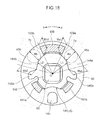
- FIG. 18 enlargedly illustrates a positional relationship between the opposing wall section 144 of the sun gear 4 and the inner peripheral wall 50 of the first holding member 5a.
- the opposing wall section 144 of the sun gear 4 is disposed to be opposed to the inner peripheral wall 50 of the first holding member 5a, while being radially spaced apart from each other.
- the opposing wall section 144 has a first wall surface region 144a on a leading side thereof with respect to the specific direction X, and a second wall surface region 144b on a leading side thereof with respect to the counter direction Y.
- a region of an outer peripheral surface of the opposing wall section 144 on a leading side with respect to the specific direction X is a first wall surface region 144a
- a region of the outer peripheral surface of the opposing wall section 144 on a leading side with respect to the counter direction Y is a second wall surface region 144b.
- the first wall surface region 144a of the opposing wall section 144 is formed such that a distance L1 from a center O of the sun gear 4 gradually increases toward the counter direction Y.
- the second wall surface region 144b of the opposing wall section 144 is formed such that a distance L2 from the center O of the sun gear 4 gradually increases toward the specific direction X.
- the first pushable section 145a and the second pushable section 145b are provides, respectively, at two circumferential positions of the convex portion 143 on both sides of the opposing wall section 144, to protrude radially from the convex portion 143. More specifically, the first pushable section 145a is provided at a position adjacent to a leading edge of the second wall surface region 144b of the opposing wall section 144 with respect to the counter direction Y, and the second pushable section 145b is provided at a position adjacent to a leading edge of the first wall surface region 144a of the opposing wall section 144 with respect to the specific direction X.
- the locking protrusion 146 is formed such that a part of the one lateral surface (in FIG. 12 , the right surface) of the gear portion 141 is convexed by approximately the same distance as that of the convex portion 143, and provided at a position radially spaced apart from the convex portion 143 by a predetermined distance (in FIG. 17 , on a lower side of the convex portion 143).
- the first wall surface region 144a of the opposing wall section 144 of the sun gear 4 and the inner peripheral wall 50 of the first holding member 5a define therebetween a first wedge-shaped space 48a, and the first restriction member 7a is displaceably disposed in the first wedge-shaped space 48a.
- the second wall surface region 144b of the opposing wall section 144 of the sun gear 4 and the inner peripheral wall 50 of the first holding member 5a define therebetween a second wedge-shaped space 48b, and the second restriction member 7b is displaceably disposed in the second wedge-shaped space 48b.
- a width Wa (see FIG. 18 ) of the first wedge-shaped space 48a is set to gradually become narrowed toward the counter direction Y, according to the aforementioned shape of the first wall surface region 144a of the opposing wall section 144. Specifically, because the distance L1 of the first wall surface region 144a from the center O of the sun gear 4 gradually increases toward the counter direction Y, a radial distance (clearance) between the first wall surface region 144a and the inner peripheral wall 50 of the first holding member 5a, i.e., a value of the width Wa of the first wedge-shaped space 48a, gradually decreases toward the counter direction Y.
- a width Wb (see FIG. 18 ) of the second wedge-shaped space 48b is set to gradually become narrowed toward the specific direction X, according to the aforementioned shape of the second wall surface region 144b of the opposing wall section 144. Specifically, because the distance L2 of the second wall surface region 144b from the center O of the sun gear 4 gradually increases toward the specific direction X, a radial distance (clearance) between the second wall surface region 144b and the inner peripheral wall 50 of the first holding member 5a, i.e., a value of the width Wb of the second wedge-shaped space 48b, gradually decreases toward the specific direction X.
- the sun gear operating member 6 is composed of a circular disk-shaped plate. More specifically, as illustrated in FIG. 16 , the sun gear operating member 6 integrally has: a first push-operation portion 161a and a second push-operation portion 161b protrudingly provided, respectively, at two positions on a lower region of a lateral surface thereof on the side of the first holding member 5a and the sun gear 4 (in FIG. 12 , a left surface); and a restriction releasing convex portion 109 protrudingly provided on an upper region of the lateral surface. Further, a quadrangular-shaped shaft coupling hole 164 is provided in a central region of the sun gear operating member 6 located between the first and second push-operation portions 161a, 161b, and the restriction releasing convex portion 109.
- the first push-operation portion 161a is a member for pushing and rotating the sun gear 4 in the specific direction X, and formed to protrude from the lateral surface of the sun gear operating member 6 on the side of the sun gear 4, by a predetermined distance, and extend for a short distance in an arc pattern along a circumferential direction of the sun gear operating member 6.
- the second push-operation portion 161b is a member for pushing and rotating the sun gear 4 in the counter direction Y, and formed to protrude from the lateral surface of the sun gear operating member 6 on the side of the sun gear 4, by a predetermined distance, and extend for a short distance in an arc pattern along the circumferential direction of the sun gear operating member 6.
- the restriction releasing convex portion 109 is a member for releasing respective restrictions by the first and second restriction members 7a, 7b, and formed to protrude from the lateral surface of the sun gear operating member 6 on the side of the sun gear 4, by a predetermined distance, and extend in an arc pattern along the circumferential direction of the sun gear operating member 6.
- the restriction releasing convex portion 109 has a first restriction releasing section 109a provided at one of opposite ends thereof (an end on a leading side with respect to the specific direction X) in the circumferential direction of the sun gear operating member 6 to release a restriction by the first restriction member 7a, and a second restriction releasing section 109b provided at the other end (an end on a leading side with respect to the counter direction Y) in the circumferential direction of the sun gear operating member 6 to release a restriction by the second restriction member 7b.
- the restriction releasing convex portion 109 is disposed in a gap between the inner peripheral wall 50 of the first holding member 5a and the convex portion 143 of the sun gear 4, at a position between the first restriction member 7a and the second restriction member 7b, in a circumferentially displaceable manner.
- the first restriction releasing section 109a is located opposed to the first restriction member 7a
- the second restriction releasing section 109b is located opposed to the second restriction member 7b.
- a gap t11 defined between the first restriction releasing section 109a of the restriction releasing convex portion 109 and the first restriction member 7a is set to become less than a gap t13 defined between the first push-operation portion 161a of the sun gear operating member 6 and the first pushable section 145a of the sun gear 4.
- a gap t12 defined between the second restriction releasing section 109b of the restriction releasing convex portion 109 and the second restriction member 7b is set to become less than a gap t14 defined between the second push-operation portion 161b of the sun gear operating member 6 and the second pushable section 145b of the sun gear 4.
- the sun gear operating member 6 configured as above is non-rotatably coupled to a manual operation dial 66 through an aftermentioned rotary shaft 65.
- a square pillar-shaped rotary shaft 65 is disposed in a coupling portion between the seat back 102 and the seat cushion 101 of the seat 100 (see FIG. 1 ), rotatably with respect to the seat back 102 and a seat cushion 101.
- the rotary shaft 65 has a first end 65 a which is rotatably inserted into the second holding member 5b, a circular hole 11 of the first plate 1, a circular hole 21 of the second plate 2, the shaft insertion hole 142 of the sun gear 4, and the first holding member 5a, in this order.
- the first end 65a of the rotary shaft 65 inserted in the above members is non-rotatably fitted into the shaft coupling hole 164 of the sun gear operating member 6.
- the rotary shaft 65 is disposed in a freely relatively rotatable manner with respect to the second holding member 5b, the first plate 1, the second plate 2, the sun gear 4 and the first holding member 5a, and in a relatively non-rotatable manner with respect to the sun gear operating member 6.
- the first end 65a of the rotary shaft 65 fitted in the shaft coupling hole 164 of the sun gear operating member 6 is further coupled to the manual operation dial 66 illustrated in FIG. 12 , in a relatively non-rotatable manner. Therefore, according to rotation of the manual operation dial 66, the rotary shaft 65 is rotated, and, according to this rotation, the sun gear operating member 6 is rotated.
- the first and second restriction members 7a, 7b will be described below.
- the first restriction member 7a is designed to restrict the first and second holding members 5a, 5b from being rotated with respect to the sun gear 4 in the specific direction X, and disposed within the first wedge-shaped space 48a.
- the second restriction member 7b is designed to restrict the first and second holding members 5a, 5b from being rotated with respect to the sun gear 4 in the counter direction Y, and disposed within the second wedge-shaped space 48b.
- the first restriction member 7a is composed of a columnar-shaped roller.
- An outer diameter of the first restriction member 7a is set to be less than a width (maximum width) Wa2 of an end of the first wedge-shaped space 48a on a leading side with respect to the specific direction X, and greater than a width (minimum width) Wa1 of an end of the first wedge-shaped space 48a on a leading side with respect to the counter direction Y.
- the second restriction member 7b has the same configuration as that of the first restriction member 7a, and an outer diameter of the second restriction member 7b is set to be less than a width (maximum width) Wb2 of an end of the second wedge-shaped space 48b on a leading side with respect to the counter direction Y, and greater than a width (minimum width) Wb1 of an end of the second wedge-shaped space 48b on a leading side with respect to the specific direction X.
- the biasing member 108 will be described below. As illustrated in FIGS. 12 , 13 and 17 , the biasing member 108 is composed of an open ring-shaped member which has one end provided with a first-restriction-member pushing portion 181 for pushing the first restriction member 7a, and the other end provided with a second-restriction-member pushing portion 182 for pushing the second restriction member 7b.
- an intermediate portion of the biasing member 108 between the first-restriction-member pushing portion 181 and the second-restriction-member pushing portion 182 is formed as an engagement concavely-curved portion 183 adapted to be locked to the locking protrusion 146 of the sun gear 4.
- the biasing member 108 configured as above is disposed in the gap between the convex portion 143 of the sun gear 4 and the inner peripheral wall 50 of the first holding member 5a, in a state in which the engagement concavely-curved portion 183 is locked to the locking protrusion 146 of the sun gear 4.
- the first-restriction-member pushing portion 181 of the biasing member 108 is located in contact with the first restriction member 7a within the first wedge-shaped space 48a to bias the first restriction member 7a toward the counter direction Y.
- the second-restriction-member pushing portion 182 of the biasing member 108 is located in contact with the second restriction member 7b within the second wedge-shaped space 48b to bias the second restriction member 7b toward the specific direction X.
- the first restriction member 7a is biased in the counter direction Y by the first-restriction-member pushing portion 181 of the biasing member 108, so that the first restriction member 7a is reliably pushed toward the counter direction Y without being displaced in the specific direction X in conjunction with the above movement.
- the first restriction member 7a When the first restriction member 7a is relatively pushed toward the counter direction Y (i.e., in a direction causing the width of the first wedge-shaped space 48a to become narrower), the first restriction member 7a is brought into such a situation that it bites into a narrow region of the first wedge-shaped space 48a, so that a force is applied to the opposing wall section 144 of the sun gear 4 and the inner peripheral wall 50 of the first holding member 5a to urge them to be displaced away from each other while interposing the first restriction member 7a therebetween.
- the first holding member 5a and the sun gear 4 receiving this force act to press the planetary gears 3a to 3c against the internal gears 12, 22 of the first and second plates 1, 2, so that a gap corresponding to a backlash between each of the gear portions 31 of the planetary gears 3a to 3c and a respective one of the internal gears 12, 22 of the first and second plates 1, 2 is eliminated.
- the second restriction member 7b is biased in the specific direction X by the second-restriction-member pushing portion 182 of the biasing member 108, so that the second restriction member 7b is reliably pushed toward the specific direction X without being displaced in the counter direction Y in conjunction with the above movement.
- the second restriction member 7b When the second restriction member 7b is relatively pushed toward the specific direction X (i.e., in a direction causing the width of the second wedge-shaped space 48b to become narrower), the second restriction member 7b is brought into such a situation that it bites into a narrow region of the second wedge-shaped space 48b, so that a force is applied to the opposing wall section 144 of the sun gear 4 and the inner peripheral wall 50 of the first holding member 5a to urge them to be displaced away from each other while interposing the second restriction member 7b therebetween.
- the first holding member 5a and the sun gear 4 receiving this force act to press the planetary gears 3a to 3c against the internal gears 12, 22 of the first and second plates 1, 2, so that a gap corresponding to a backlash between each of the gear portions 31 of the planetary gears 3a to 3c and a respective one of the internal gears 12, 22 of the first and second plates 1, 2 is eliminated.
- the sun gear operating member 6 When the manual operation dial 66 is rotationally operated in the specific direction X, the sun gear operating member 6 is rotated in the same direction through the rotary shaft 65. According this rotation, the first restriction releasing section 109a of the restriction releasing convex portion 109 of the sun gear operating member 6 is brought into contact with the first restriction member 7a, as illustrated FIG. 19 . Before rotationally operating the sun gear operating member 6, the sun gear operating member 6 is set to satisfy the aforementioned dimensional relation t11 ⁇ t13 (see FIG. 17 ). Thus, at a timing in FIG. 19 , the first push-operation portion 161a of the sun gear operating member 6 has not been brought into contact with the first pushable section 145a of the sun gear 4.
- the first restriction releasing section 109a of the restriction releasing convex portion 109 is adapted to be brought into contact with the first restriction member 7a before the first push-operation portion 161a is brought into contact with the first pushable section 145a. Subsequently, when the sun gear operating member 6 is further rotated, the first restriction releasing section 109a of the restriction releasing convex portion 109 pushes the first restriction member 7a against a biasing force of the biasing member 108 to displace the first restriction member 7a in the specific direction X (i.e., a direction causing the width Wa of the first wedge-shaped space 48a to become wider) within the first wedge-shaped space 48a.
- X i.e., a direction causing the width Wa of the first wedge-shaped space 48a to become wider
- the first restriction member 7a is displaced in the specific direction X.
- the rotational restriction by the first restriction member 7a is released, and the sun gear 4 becomes rotatable with respect to the first holding member 5a.
- the sun gear operating member 6 is further rotated in the above restriction released state, the first push-operation portion 161a is brought into contact with the first pushable section 145a of the sun gear 4, as illustrated in FIG. 20 .
- the first push-operation portion 161a pushes the first pushable section 145a of the sun gear 4 in the specific direction X to rotate the sun gear 4 in the same direction, under the condition that the restriction released state is maintained.
- the sun gear 4 is rotated in the specific direction X.
- each of the planetary gears 3a to 3c in meshing engagement with the sun gear 4 is rollingly displaced along the internal gears 12, 22 of the first and second plates 1, 2 (i.e., revolved around the sun gear 4 in the specific direction X while being rotated on its own axis).
- the first plate 1 is relatively rotated with respect to the second plate 2 in the specific direction X, because the number of teeth in the internal gear 12 of the first plate 1 is greater than the number of teeth in the internal gear 22 of the second plate 2, so that the seat back 102 will be displaced in the rearward tilting direction R.
- the second restriction member 7b in the second wedge-shaped space 48b is relatively displaced in the counter direction Y (i.e., a direction causing the width Wb of the second wedge-shaped space 48b to become wider), so that the rotation of the sun gear 4 in the specific direction X is never restricted.
- the sun gear operating member 6 When the manual operation dial 66 is rotationally operated in the counter direction Y, the sun gear operating member 6 is rotated in the same direction through the rotary shaft 65. According this rotation, the second restriction releasing section 109b of the restriction releasing convex portion 109 of the sun gear operating member 6 is brought into contact with the second restriction member 7b, although not illustrated. Before rotationally operating the sun gear operating member 6, the sun gear operating member 6 is set to satisfy the aforementioned dimensional relation t12 ⁇ t14 (see FIG. 17 ). Thus, at this timing, the second push-operation portion 161b of the sun gear operating member 6 has not been brought into contact with the second pushable section 145b of the sun gear 4.
- the second restriction releasing section 109b of the restriction releasing convex portion 109 is adapted to be brought into contact with the second restriction member 7b before the second push-operation portion 161b is brought into contact with the second pushable section 145b. Subsequently, when the sun gear operating member 6 is further rotated, the second restriction releasing section 109b of the restriction releasing convex portion 109 pushes the second restriction member 7b against a biasing force of the biasing member 108 to displace the second restriction member 7b in the counter direction Y (i.e., a direction causing the width Wb of the second wedge-shaped space 48b to become wider) within the second wedge-shaped space 48b.
- Y i.e., a direction causing the width Wb of the second wedge-shaped space 48b to become wider
- the second restriction member 7b is displaced in the counter direction Y.
- the rotational restriction by the second restriction member 7b is released, and the sun gear 4 becomes rotatable with respect to the first holding member 5a.
- the sun gear operating member 6 is further rotated in the above restriction released state, the second push-operation portion 161b is brought into contact with the second pushable section 145b of the sun gear 4.
- the second push-operation portion 161b pushes the second pushable section 145b of the sun gear 4 in the counter direction Y to rotate the sun gear 4 in the same direction, under the condition that the restriction released state is maintained.
- the sun gear 4 is rotated in the counter direction Y.
- each of the planetary gears 3a to 3c in meshing engagement with the sun gear 4 is rollingly displaced along the internal gears 12, 22 of the first and second plates 1, 2 (i.e., revolved around the sun gear 4 in the counter direction Y while being rotated on its own axis).
- the first plate 1 is relatively rotated with respect to the second plate 2 in the counter direction Y, because the number of teeth in the internal gear 12 of the first plate 1 is greater than the number of teeth in the internal gear 22 of the second plate 2, so that the seat back 102 will be displaced in the forward tilting direction F.
- the first restriction member 7a in the first wedge-shaped space 48a is relatively displaced in the specific direction X (i.e., a direction causing the width Wa of the first wedge-shaped space 48a to become wider), so that the rotation of the sun gear 4 in the counter direction Y is never restricted.
- the present invention is not limited to only the first and second embodiments but various changes and modifications may be made therein.
- the reclining mechanism of the present invention has been applied to an automobile seat.
- the present invention may also be applied to a seat for various other apparatuses, such as trains and airplanes.
- the reclining mechanism comprises: a ring-shaped first plate fixed to a seat back; a ring-shaped second plate capable of rotating with respect to the first plate and fixed to a seat cushion; a plurality of planetary gears in meshing engagement with internal gears provided in respective inner peripheries of the first plate and the second plate; a sun gear in meshing engagement with the planetary gears; a holding member rotatably holding the planetary gears and having an inner peripheral wall surrounding the sun gear; and a restriction member for restricting a rotation of the holding member with respect to the sun gear.
- the sun gear has an opposing wall section opposed to the inner peripheral wall of the holding member.
- the opposing wall section of the sun gear and the inner peripheral wall of the holding member define therebetween a wedge-shaped space in which the restriction member is displaceably disposed.
- the opposing wall section of the sun gear is formed such that a width of the wedge-shaped space is gradually narrowed toward a counter direction with respect to a specific direction, where the specific direction is a direction along which the first plate is urged to be rotated according to a force applied to the seat back in a rearward tilting direction, and the counter direction is a direction opposite to the specific direction.
- the restriction member When the restriction member is pushed toward the counter direction (i.e., in a direction causing a width of the wedge-shaped space to become narrower), the restriction member is brought into such a situation that it bites into a narrow region of the wedge-shaped space, so that a force is applied to the opposing wall section of the sun gear and the inner peripheral wall of the holding member to urge them to be displaced away from each other while interposing the restriction member therebetween.
- the holding member receiving this force acts to press at least a specific one of the planetary gears against the internal gears of the first and second plates, so that a gap which would otherwise occur between the specific planetary gear and each of the internal gears of the first and second plates is eliminated.
- the sun gear receiving the above force acts to press each of the gear portions of the remaining planetary gears against the internal gears of the first and second plates, so that a gap which would otherwise occur between each of the remaining planetary gears and a respective one of the internal gears of the first and second plates is eliminated.
- each of the planetary gears is pressed against the internal gears of the first and second plates (and thereby a gap between the planetary and internal gears is eliminated), so that the planetary gears are precluded from being gradually rollingly displaced with respect to the internal gears of the first and second plates (i.e., a rotation of the holding member is restricted).
- the planetary gears and the holding member can be reliably maintained in a fixed state to effectively prevent the seat back from being gradually moved in the rearward tilting direction.
- the above reclining mechanism further comprises a biasing member biasing the restriction member disposed in the wedge-shaped space, in the counter direction.
- the restriction member it becomes possible to prevent the restriction member from being displaced in the specific direction in conjunction with a movement of the holding member.
- the restriction member can be reliably pushed toward the counter direction (in a direction causing the width of the wedge-shaped space to become narrower) so as to maintain the seat back in a fixed state.
- the reclining mechanism having the above feature further comprises a sun gear operating member for rotationally operating the sun gear.
- the sun gear operating member has a restriction releasing convex portion for releasing the restriction by the restriction member.
- the restriction releasing convex portion pushes, according to a movement of the sun gear operating member for rotationally operating the sun gear in the specific direction, the restriction member against a biasing force of the biasing member to displace the restriction member in the specific direction within the wedge-shaped space.
- the restriction releasing convex portion is operable to push and displace the restriction member toward the specific direction (in a direction causing the width of the wedge-shaped space to become wider) according to a rotation of the sun gear operating member, so that it becomes possible to avoid a situation where the rotational operation of the sun gear is hindered by the restriction member, and smoothly perform the rotational operation of the sun gear by using the sun gear operating member.
- the sun gear operating member has a push-operation portion for pushing the sun gear to rotate it.
- the restriction releasing convex portion pushes and displaces, according to a movement of the sun gear operating member for rotationally operating the sun gear in the specific direction, the restriction member in the specific direction, before the push-operation portion pushes the sun gear.
- the restriction releasing convex portion is operable to push and displace the restriction member toward the specific direction (in a direction causing the width of the wedge-shaped space to become wider) before the push-operation portion pushes the sun gear, so that it becomes possible to more reliably avoid the situation where the rotational operation of the sun gear is hindered by the restriction member.
- the restriction member is composed of a columnar-shaped member having a locking hole along an axis thereof.
- the biasing member has: an open ring-shaped member body; a sun gear engagement section provided at one end of the member body and locked to the sun gear; and a restriction member engagement section provided at the other end of the member body and inserted in the locking hole of the restriction member.
- the restriction member engagement section of the biasing member is inserted into the locking hole provided in the restriction member along an axis thereof.
- the restriction member can be reliably biased in the counter direction by the biasing member while preventing the restriction member from being disengaged from the biasing member.
- the opposing wall section of the sun gear has a first wall surface region and a second wall surface region.
- the first wall surface region of the opposing wall section and the inner peripheral wall of the holding member define therebetween the wedge-shaped space referred to as a first wedge-shaped space whose width is gradually narrowed toward the counter direction
- the second wall surface region of the opposing wall section and the inner peripheral wall of the holding member define therebetween a second wedge-shaped space whose width is gradually narrowed toward the specific direction.
- the restriction member referred to as a first restriction member is displaceably disposed in the first wedge-shaped space to restrict the holding member from being rotated with respect to the sun gear in the specific direction.
- the reclining mechanism further comprises a second restriction member displaceably disposed in the second wedge-shaped space to restrict the holding member from being rotated with respect to the sun gear in the counter direction.
- the first restriction member when a force in the rearward tilting direction is applied to the seat back, the first restriction member is relatively pushed toward the counter direction (i.e., in a direction causing a width of the first wedge-shaped space to become narrower) within the first wedge-shaped space, and thereby a force is applied to the opposing wall section of the sun gear and the inner peripheral wall of the holding member to urge them to be displaced away from each other while interposing the first restriction member therebetween, so that it becomes possible to eliminate a gap between each of the planetary gears and a respective one of the internal gears of the first and second plates, and thus prevent rolling displacement of the planetary gears.
- the planetary gears and the holding member can be reliably maintained in a fixed state to effectively prevent the seat back from being moved in the rearward tilting direction.
- the second restriction member when a force in a forward tilting direction is applied to the seat back, the second restriction member is relatively pushed toward the specific direction (i.e., in a direction causing a width of the second wedge-shaped space to become narrower) within the second wedge-shaped space, and thereby a force is applied to the opposing wall section of the sun gear and the inner peripheral wall of the holding member to urge them to be displaced away from each other while interposing the second restriction member therebetween, so that it becomes possible to eliminate a gap between each of the planetary gears and a respective one of the internal gears of the first and second plates, and thus prevent rolling displacement of the planetary gears.
- the planetary gears and the holding member can be reliably maintained in a fixed state to effectively prevent the seat back from being moved in the forward tilting direction.
- the reclining mechanism having the above feature further comprises: a biasing member biasing the first restriction member disposed in the first wedge-shaped space, in the counter direction, and biasing the second restriction member disposed in the second wedge-shaped space, in the specific direction; and a sun gear operating member for rotationally operating the sun gear.
- the sun gear operating member has a first restriction releasing section for releasing the restriction by the first restriction member, and a second restriction releasing section for releasing the restriction by the second restriction member.
- the first restriction releasing section pushes, according to a movement of the sun gear operating member for rotationally operating the sun gear in the specific direction, the first restriction member against a biasing force of the biasing member to displace the first restriction member in the specific direction within the first wedge-shaped space.
- the second restriction releasing section pushes, according to a movement of the sun gear operating member for rotationally operating the sun gear in the counter direction, the second restriction member against a biasing force of the biasing member to displace the second restriction member in the counter direction within the second wedge-shaped space.
- the biasing member is operable to bias the first restriction member toward the counter direction (in a direction causing the width of the first wedge-shaped space to become narrower), and biasing the second restriction member toward the specific direction (in a direction causing the width of the second wedge-shaped space to become narrower).
- the first restriction member or the second restriction member can be reliably maintained in a fixed state by using the first restriction member or the second restriction member.
- the first restriction releasing section is operable to push and displace the first restriction member toward the specific direction (in a direction causing the width of the first wedge-shaped space to become wider) according to the rotation of the sun gear operating member, so that it becomes possible to avoid a situation where the rotational operation of the sun gear is hindered by the first restriction member, and smoothly perform the rotational operation of the sun gear by using the sun gear operating member.
- the second restriction releasing section is operable to push and displace the second restriction member toward the counter direction (in a direction causing the width of the second wedge-shaped space to become wider) according to the rotation of the sun gear operating member, so that it becomes possible to avoid a situation where the rotational operation of the sun gear is hindered by the second restriction member, and smoothly perform the rotational operation of the sun gear by using the sun gear operating member.
- the sun gear operating member has a first push-operation portion for pushing the sun gear to rotate it in the specific direction, and a second push-operation portion for pushing the sun gear to rotate it in the counter direction.
- the first restriction releasing section pushes and displaces, according to a movement of the sun gear operating member for rotationally operating the sun gear in the specific direction, the first restriction member in the specific direction, before the first push-operation portion pushes the sun gear.
- the second restriction releasing section pushes and displaces, according to a movement of the sun gear operating member for rotationally operating the sun gear in the counter direction, the second restriction member in the counter direction, before the second push-operation portion pushes the sun gear.
- the first restriction releasing section is operable to push and displace the first restriction member toward the specific direction (in a direction causing the width of the first wedge-shaped space to become wider) before the first push-operation portion pushes the sun gear, so that it becomes possible to more reliably avoid the situation where the rotational operation of the sun gear is hindered by the first restriction member.
- the second restriction releasing section is operable to push and displace the second restriction member toward the counter direction (in a direction causing the width of the second wedge-shaped space to become wider) before the second push-operation portion pushes the sun gear, so that it becomes possible to more reliably avoid the situation where the rotational operation of the sun gear is hindered by the second restriction member.
Landscapes
- Engineering & Computer Science (AREA)
- Mechanical Engineering (AREA)
- Aviation & Aerospace Engineering (AREA)
- Transportation (AREA)
- General Engineering & Computer Science (AREA)
- Chairs For Special Purposes, Such As Reclining Chairs (AREA)
- Retarders (AREA)
Abstract
Disclosed is a reclining mechanism comprising: a first plate (1) fixed to a seat back; a second plate (2) fixed to a seat cushion; a plurality of planetary gears (3) in meshing engagement with internal gears of the first and second plates; a sun gear (4) in meshing engagement with the planetary gears; and a holding member (5) rotatably holding the planetary gears. An inner peripheral wall of the holding member and an opposing wall section of the sun gear define therebetween a wedge-shaped space in which a restriction member (7) is displaceably disposed. The opposing wall section of the sun gear is formed such that a width of the wedge-shaped space is gradually narrowed toward a counter direction opposite to a specific direction along which the first plate is urged to be rotated according to a force applied to the seat back in a rearward tilting direction.
Description
- The present invention relates to a reclining mechanism for a seat such as a vehicle seat.
- Heretofore, there has been known a reclining mechanism for a seat such as a vehicle seat, as disclosed, for example, in Japanese Utility Model Laid-Open Publication No.
05-001335 Patent Document 1"). A reclining mechanism disclosed in thePatent Document 1 comprises: a base plate (first plate) and an arm plate (second plate) coaxially supported in a rotatable manner and formed, respectively, with two opposed circular holes having an internal gear (internally-toothed gear) section thereinside; a control gear provided on a rotary shaft of the two plates; a plurality of planetary gears arranged in meshing engagement with the internal gear section of the plates and the control gear, and each protrudingly provided with a boss portion at an axis thereof; and a holding member rotatably holding each of the planetary gears at a trajectory of revolution thereof. This holding member is composed of a spring member which is adapted to contact the respective boss portions of the planetary gears while permitting a rotation thereof, and bias each of the planetary gears in a radial direction (in a direction causing the planetary gear to be brought in meshing engagement with the internal gear section of the plates. This reclining mechanism can suppress wobbling due to a backlash between the internal gear section of the two plates (base and arm plates) and each of the planetary gears, etc. - However, even in the case where the planetary gears are biased by the holding member composed of a spring member as described in the
Patent Document 1, for example, when a force equal to or greater than a biasing force of the holding member is applied to a seat back, the planetary gears are likely to be displaced radially inwardly against the biasing force of the holding member, causing wobbling between the internal gear section of the plates and each of the planetary gears. On the other hand, if the biasing force of the holding member is increased, a rotational resistance of each of the planetary gears becomes larger, precluding smooth rotation thereof. As above, the technique using the holding member composed of a spring member as in thePatent Document 1 has a problem of being unable to sufficiently suppress wobbling between the internal gear section of the plates and each of the planetary gears. - Moreover, in the reclining mechanism disclosed in the
Patent Document 1, when a force is repeatedly applied to the seat back in a rearward tilting direction thereof, each of the planetary gears is likely to being slightly rollingly displaced with respect to the internal gear section of the plates. If this situation occurs, the seat back will be gradually tilted rearwardly with respect to a seat cushion, thereby making it impossible to maintain the seat back in a fixed state. - It is an object of the present invention to provide a reclining mechanism capable of preventing each planetary gear from being rollingly displaced according to a force repeatedly applied to a seat back so as to reliably maintain the seat back in a fixed state.
- In order to achieve the above object, the present invention provides a reclining mechanism which comprises: a ring-shaped first plate fixed to a seat back; a ring-shaped second plate capable of rotating with respect to the first plate and fixed to a seat cushion; a plurality of planetary gears in meshing engagement with internal gears provided in respective inner peripheries of the first plate and the second plate; a sun gear in meshing engagement with the planetary gears; a holding member rotatably holding the planetary gears and having an inner peripheral wall surrounding the sun gear; and a restriction member for restricting a rotation of the holding member with respect to the sun gear. The sun gear has an opposing wall section opposed to the inner peripheral wall of the holding member. The opposing wall section of the sun gear and the inner peripheral wall of the holding member define therebetween a wedge-shaped space in which the restriction member is displaceably disposed. The opposing wall section of the sun gear is formed such that a width of the wedge-shaped space is gradually narrowed toward a counter direction with respect to a specific direction, where the specific direction is a direction along which the first plate is urged to be rotated according to a force applied to the seat back in a rearward tilting direction, and the counter direction is a direction opposite to the specific direction.
-
-
FIG. 1 is a side view of an automobile seat equipped with a reclining mechanism according to a first embodiment of the present invention. -
FIG. 2 is an exploded perspective view illustrating a structure of a substantial part of the reclining mechanism according to the first embodiment. -
FIG. 3 is a plan view illustrating an internal structure of the reclining mechanism according to the first embodiment. -
FIG. 4 is a sectional view taken along the line IV-IV inFIG. 3 . -
FIG. 5 is a sectional view taken along the line V-V inFIG. 3 . -
FIG. 6 is a perspective view separately illustrating a sun gear operating member provided in the reclining mechanism according to the first embodiment. -
FIG. 7 is an explanatory view illustrating a positional relationship between a restriction member and a restriction releasing convex portion each provided in the reclining mechanism according to the first embodiment. -
FIG. 8 is an explanatory view enlargedly illustrating a shape of a wedge-shaped space inFIG. 7 . -
FIG. 9 is an explanatory view illustrating the positional relationship, in a state in which the sun gear operating member is rotated from the state inFIG. 7 in a clockwise direction. -
FIG. 10 is an explanatory view illustrating the positional relationship, in a state in which the sun gear operating member is further rotated from the state inFIG. 9 . -
FIG. 11 is an explanatory view illustrating the positional relationship, in a state in which the sun gear operating member is rotated from the state inFIG. 10 in a counterclockwise direction. -
FIG. 12 is an exploded perspective view illustrating a structure of a substantial part of the reclining mechanism according to a second embodiment of the present invention. -
FIG. 13 is a plan view illustrating an internal structure of the reclining mechanism according to the second embodiment. -
FIG. 14 is a sectional view taken along the line XIV-XIV inFIG. 13 . -
FIG. 15 is a sectional view taken along the line XV-XV inFIG. 13 . -
FIG. 16 is a perspective view separately illustrating a sun gear operating member provided in the reclining mechanism according to the second embodiment. -
FIG. 17 is an explanatory view illustrating a positional relationship between a restriction member and a restriction releasing section each provided in the reclining mechanism according to the second embodiment. -
FIG. 18 is an explanatory view enlargedly illustrating shapes of first and second wedge-shaped spaces inFIG. 17 . -
FIG. 19 is an explanatory view illustrating the positional relationship, in a state in which the sun gear operating member is rotated from the state inFIG. 17 in a clockwise direction. -
FIG. 20 is an explanatory view illustrating the positional relationship, in a state in which the sun gear operating member is further rotated from the state inFIG. 19 . -
FIG. 21 is an explanatory view illustrating the positional relationship, in a state in which the sun gear operating member is further rotated from the state inFIG. 20 . - With reference to
FIG. 1 to FIG. 11 , a first embodiment of the present invention will now be described in detail. - A reclining
mechanism 10 according to the first embodiment is designed to be used in anautomobile seat 100, as illustrated inFIG. 1 . As illustrated inFIGS. 2 to 6 , the recliningmechanism 10 comprises: afirst plate 1; asecond plate 2; a plurality ofplanetary gears 3a to 3c; asun gear 4; afirst holding member 5a and asecond holding member 5b which hold theplanetary gears 3a to 3c; a sungear operating member 6 for rotationally operating thesun gear 4; arestriction member 7 for restricting a rotation of theholding members biasing member 8 biasing therestriction member 7. - The
first plate 1 is composed of a ring-shaped plate having acircular hole 11 in a central region thereof. An inner periphery of thefirst plate 1 surrounding thecircular hole 11 is provided with an internal gear (internally-toothed gear) 12 over the entire circumference thereof. In this embodiment, theinternal gear 12 of thefirst plate 1 is composed of thirty-eight teeth. - The
first plate 1 has a receivingportion 13 provided in one lateral surface (inFIG. 2 , a right surface) thereof. Thereceiving portion 13 is formed such that a center-side annular region of the one lateral surface of thefirst plate 1 is concaved by a predetermined depth. - The
first plate 1 configured as above is fixedly attached to a seat back 102 (seeFIG. 1 ) of theseat 100. - The
second plate 2 is composed of a ring-shaped plate formed in approximately the same shape as that of thefirst plate 1 to have acircular hole 21 in a central region thereof. An inner periphery of thesecond plate 2 surrounding thecircular hole 21 is provided with an internal gear (internally-toothed gear) 22 over the entire circumference thereof. In this embodiment, theinternal gear 22 of thesecond plate 2 is composed of thirty-five teeth. - The
second plate 2 has aconcave portion 23 provided in one lateral surface (inFIG. 2 , a right surface) thereof. Theconcave portion 23 is formed such that a center-side annular region of the one lateral surface of thesecond plate 2 is concaved by a predetermined depth. - The
second plate 2 also has afitting portion 24 provided in the other lateral surface (inFIG. 2 , a left surface) thereof. Thefitting portion 24 is formed such that a center-side annular region of the other lateral surface of thesecond plate 2 is convexed by a predetermined distance. Thefitting portion 24 is adapted to be rotatably fitted in thereceiving portion 13 of thefirst plate 1. - When the
fitting portion 24 of thesecond plate 2 is fitted into thereceiving portion 13 of thefirst plate 1, theinternal gear 12 of thefirst plate 1 and theinternal gear 22 of thesecond plate 2 are superposed together while aligning the centers thereof with each other. - The
second plate 2 configured as above is fixedly attached to a seat cushion 101 (seeFIG. 1 ) of theseat 100. - In this embodiment, the plurality of
planetary gears 3a to 3c consist of three planetary gears each having the same configuration. Each of theplanetary gears 3a to 3c has agear portion 31 with ten teeth, and ashaft portion 32 protrudingly provided on respective opposite sides of thegear portion 31 in an axial direction thereof. - The
first holding member 5a is equivalent to a "holding member" set forth in the appended claims, and disposed on one side (inFIG. 2 , the right side) of each of theplanetary gears 3a to 3c in the axial direction. Thesecond holding member 5b is disposed on the other side (inFIG. 2 , the left side) of each of theplanetary gears 3a to 3c in the axial direction, and formed to have approximately the same structure as thefirst holding member 5a. Thefirst holding member 5a and thesecond holding member 5b are coupled together by threecoupling members 52a arranged in a circumferential direction thereof. - The
first holding member 5a is composed of a ring-shaped plate member having a circular innerperipheral wall 50. Thefirst holding member 5a is provided with threeshaft holding holes 51 for holding therespective shaft portions 32 of theplanetary gears 3a to 3c, and threeinsertion holes 52 for allowing therespective coupling members 52a to be inserted thereinto. - The three
shaft holding holes 51 are arranged at even intervals along a pitch circle being concentric with the innerperipheral wall 50 of the first holdingmember 5a and having a predetermined radius. The threeinsertion holes 52 are arranged along a pitch circle having approximately the same radius as that of the pitch circle of the shaft holding holes 51. Each of the insertion holes 52 is located between adjacent two of the shaft holding holes 51. - The
first holding member 5a configured as above is rotatably received in theconcave portion 23 of thesecond plate 2. On the other hand, the second holdingmember 5b is attached to the other lateral surface (inFIG. 2 , a left surface) of thefirst plate 1. In this state, theshaft portions 32 of theplanetary gears 3a to 3c are inserted into respective ones of theshaft holding holes 51 of the first holdingmember 5a (and respective ones of similar holes provided in the second holdingmember 5b) and rotatably held by them. Further, thecoupling members 52a are inserted into respective ones of the insertion holes 52 of the first holdingmember 5a (and respective ones of similar holes provided in the second holdingmember 5b), so that the first holdingmember 5a and the second holdingmember 5b are coupled together through thecoupling members 52a. - As illustrated in
FIGS. 3 to 5 , thegear portion 31 of each of theplanetary gears 3a to 3c is in meshing engagement with both of theinternal gear 12 of thefirst plate 1 and theinternal gear 22 of thesecond plate 2. As the first holdingmember 5a is rotated, each of theplanetary gears 3a to 3c is displaced (revolved) in a circumferential direction of the first andsecond plates shaft portion 32 thereof (rotated on its own axis). - The
sun gear 4 will be described below. As illustrated inFIG. 2 , thesun gear 4 has agear portion 41, and aconvex portion 43 provided to protrude from thegear portion 41 in an axial direction thereof. Thegear portion 41 and theconvex portion 43 are provided with ashaft insertion hole 42 penetrating through a central region thereof in the axial direction. - The
gear portion 41 has a plurality of teeth provided in an outer periphery thereof and adapted to be in meshing engagement with therespective gear portions 31 of theplanetary gears 3a to 3c. In this embodiment, sixteen teeth are provided in the outer periphery of thegear portion 41. - Then, as illustrated in
FIGS. 3 to 5 , thesun gear 4 is disposed between the first holdingmember 5a and the second holdingmember 5b in a coaxial relation to each other. The threeplanetary gears 3a to 3c are arranged around thesun gear 4 to surround thesun gear 4, and thegear portion 41 of thesun gear 4 and thegear portion 31 of each of theplanetary gears 3a to 3c are brought into meshing engagement with each other. Thus, when thesun gear 4 is rotated, each of theplanetary gears 3a to 3c is displaced (revolved) in the circumferential direction while being rotated about theshaft portion 32 thereof (rotated on its own axis), and the first andsecond holding members - The
convex portion 43 of thesun gear 4 is formed such that a part of one lateral surface (inFIG. 2 , a right surface) of thegear portion 41 is convexed in the axial direction by a predetermined distance, as a hollow raised segment surrounding theshaft insertion hole 42. As illustrated inFIG. 7 , theconvex portion 43 has: an opposingwall section 44 which defines an aftermentioned wedge-shapedspace 48 in cooperation with the innerperipheral wall 50 of the first holdingmember 5a; a firstpushable section 45a and a secondpushable section 45b provided, respectively, on circumferentially opposite sides of the opposingwall section 44; and aspring locking section 46 provided between the secondpushable section 45b and the opposingwall section 44. -
FIG. 8 enlargedly illustrates a positional relationship between the opposingwall section 44 of thesun gear 4 and the innerperipheral wall 50 of the first holdingmember 5a. As also illustrated inFIG. 8 , the opposingwall section 44 of thesun gear 4 is disposed to be opposed to the innerperipheral wall 50 of the first holdingmember 5a, while being radially spaced apart from each other. An outer peripheral surface of a region of the opposingwall section 44 located on a relatively right side inFIGS. 7 and8 (i.e., a region of the opposingwall section 44 close to the restriction member 7) is formed such that a distance L from a center O of thesun gear 4 gradually increases toward a counterclockwise direction (inFIGS. 7 and8 , direction indicated by the arrow Y). - The counterclockwise direction in
FIGS. 7 and8 is a direction opposite to a direction along which thefirst plate 1 is urged to be rotated when a force in a rearward tilting direction R is applied to the seat back 102 (seeFIG. 1 ). In the following description, the direction along which thefirst plate 1 is urged to be rotated when the force in the rearward tilting direction R is applied to the seat back 102 (inFIGS. 7 ,8 , etc., a clockwise direction) will be referred to as "specific direction X", and a direction opposite to the specific direction (inFIGS. 7 ,8 , etc., a counterclockwise direction) will be referred to as "counter direction Y". - The first
pushable section 45a and the secondpushable section 45b are provides, respectively, at two circumferential positions of theconvex portion 43 spaced apart from each other in the specific direction X and the counter direction Y with respect to the opposingwall section 44, to protrude radially from theconvex portion 43. - The
spring locking section 46 is located between the secondpushable section 45b and the opposingwall section 44, and formed to have a concave-shaped outer peripheral surface concaved radially inwardly with respect to an outer peripheral surface of the secondpushable section 45b. - The opposing
wall section 44 of thesun gear 4 and the innerperipheral wall 50 of the first holdingmember 5a define therebetween a wedge-shapedspace 48 illustrated inFIGS. 3 ,7 and8 , and therestriction member 7 is disposed in the wedge-shapedspace 48. - A width W (see
FIG. 8 ) of the wedge-shapedspace 48 is set to gradually become narrowed toward the counter direction Y, according to the aforementioned shape of the opposingwall section 44 of thesun gear 4. Specifically, because the distance L of the outer peripheral surface of the opposingwall section 44 from the center O of thesun gear 4 gradually increases toward the counter direction Y, a radial distance (clearance) between the opposingwall section 44 and the innerperipheral wall 50 of the first holdingmember 5a, i.e., a value of the width W of the wedge-shapedspace 48, gradually decreases toward the counter direction Y. - The sun
gear operating member 6 will be described below. As illustrated inFIG. 2 , the sungear operating member 6 is composed of a circular disk-shaped plate. More specifically, as illustrated inFIG. 6 , the sungear operating member 6 integrally has a push-operation portion 61 protrudingly provided on a lower region of a lateral surface thereof on the side of the first holdingmember 5a and the sun gear 4 (inFIG. 2 , a left surface), and a restriction releasingconvex portion 9 protrudingly provided on an upper region of the lateral surface. Further, a quadrangular-shapedshaft coupling hole 64 is provided in a central region of the sungear operating member 6 located between the push-operation portion 61 and the restriction releasingconvex portion 9. - The push-
operation portion 61 is a member for pushing and rotating thesun gear 4, and formed to protrude from the lateral surface of the sungear operating member 6 on the side of thesun gear 4, by a predetermined distance, and extend in an arc pattern along a circumferential direction of the sungear operating member 6. The push-operation portion 61 has afirst contact section 61a provided at one of opposite ends thereof (an end on a leading side with respect to the specific direction X) in the circumferential direction of the sungear operating member 6 and adapted to be brought into contact with the firstpushable section 45a of theconvex portion 43 of thesun gear 4, and asecond contact section 61b provided at the other end (an end on a leading side with respect to the counter direction Y) in the circumferential direction of the sungear operating member 6 and adapted to be brought into contact with the secondpushable section 45b of theconvex portion 43 of thesun gear 4. - As illustrated in
FIG. 7 , the push-operation portion 61 is disposed in a gap between the innerperipheral wall 50 of the first holdingmember 5a and an outer peripheral surface of theconvex portion 43 of thesun gear 4, at a position between the firstpushable section 45a and the secondpushable section 45b. Thus, thefirst contact section 61a of the push-operation portion 61 is located in opposed relation to the firstpushable section 45a of theconvex portion 43, and thesecond contact section 61b of the push-operation portion 61 is located in opposed relation to the secondpushable section 45b of theconvex portion 43. - The restriction releasing
convex portion 9 is a member for releasing a restriction by therestriction member 7, and formed to protrude from the lateral surface of the sungear operating member 6 on the side of thesun gear 4, by a predetermined distance, and extend in an arc pattern along the circumferential direction of the sungear operating member 6. - As illustrated in
FIGS. 3 and7 , the restriction releasingconvex portion 9 is disposed in the gap between the innerperipheral wall 50 of the first holdingmember 5a and the outer peripheral surface of theconvex portion 43 of thesun gear 4, at a position adjacent to therestriction member 7 in the counter direction Y, in a circumferentially displaceable manner. - As illustrated in
FIG. 7 , a gap t1 defined between the restriction releasingconvex portion 9 and therestriction member 7 is set to become less than a gap t2 defined between thefirst contact section 61a of the push-operation portion 61 and the firstpushable section 45 a of thesun gear 4. - The sun
gear operating member 6 configured as above is non-rotatably coupled to amanual operation dial 66 through an aftermentionedrotary shaft 65. - Specifically, a square pillar-shaped
rotary shaft 65 is disposed in a coupling portion between the seat back 102 and theseat cushion 101 of theseat 100, rotatably with respect to the seat back 102 and aseat cushion 101. As illustrated inFIG. 2 , therotary shaft 65 has afirst end 65a which is rotatably inserted into the second holdingmember 5b, thecircular hole 11 of thefirst plate 1, thecircular hole 21 of thesecond plate 2, theshaft insertion hole 42 of thesun gear 4, and the first holdingmember 5a, in this order. Further, thefirst end 65a of therotary shaft 65 inserted in the above members is non-rotatably fitted into theshaft coupling hole 64 of the sungear operating member 6. Thus, therotary shaft 65 is disposed in a freely relatively rotatable manner with respect to the second holdingmember 5b, thefirst plate 1, thesecond plate 2, thesun gear 4 and the first holdingmember 5a, and in a relatively non-rotatable manner with respect to the sungear operating member 6. - The
first end 65a of therotary shaft 65 fitted in theshaft coupling hole 64 of the sungear operating member 6 is further coupled to themanual operation dial 66 illustrated inFIG. 2 , in a relatively non-rotatable manner. Therefore, according to rotation of themanual operation dial 66, therotary shaft 65 is rotated, and, according to this rotation, the sungear operating member 6 is rotated. - The
restriction member 7 will be described below. Therestriction member 7 is designed to restrict the first andsecond holding members sun gear 4 in the specific direction X. As illustrated inFIGS. 2 and7 , in this embodiment, therestriction member 7 is composed of a columnar-shaped roller having a lockinghole 71 along an axis thereof. An outer diameter of therestriction member 7 is set to be less than a width (maximum width) W2 of an end of the wedge-shapedspace 48 on a leading side with respect to the specific direction X, and greater than a width (minimum width) W1 of an end of the wedge-shapedspace 48 on a leading side with respect to the counter direction Y. - The
restriction member 7 is disposed in a circumferentially displaceable manner within the wedge-shapedspace 48. - The biasing
member 8 will be described below. As illustrated inFIGS. 2 ,3 and7 , the biasingmember 8 has: an open ring-shapedmember body 81; a firstbended section 81a formed by bending one end of themember body 81 radially inwardly; a sungear engagement section 82 formed by bending a distal end of the firstbended section 81a in the same direction as the axial direction of thesun gear 4; a secondbended section 81b formed by bending the other end of themember body 81 radially inwardly; and a restrictionmember engagement section 83 formed by bending a distal end of the secondbended section 81b in the same direction as the axial direction of the restriction member 7 (i.e., in a direction parallel to the sun gear engagement section 82). - As illustrated in
FIG. 2 , the biasingmember 8 configured as above is disposed on the side of one lateral surface (inFIG. 2 , a right surface) of the sungear operating member 6. The sungear engagement section 82 and the restrictionmember engagement section 83 of the biasingmember 8 are inserted into anelongate hole 62 provided in the sungear operating member 6, from the side of the one lateral surface. - The sun
gear engagement section 82 inserted in theelongate hole 62 is locked to thespring locking section 46 of thesun gear 4. - On the other hand, the restriction
member engagement section 83 inserted in theelongate hole 62 is inserted in the lockinghole 71 of therestriction member 7. In this manner, the restrictionmember engagement section 83 is locked to therestriction member 7, and therestriction member 7 is biased in the counter direction Y. - An operation of the
reclining mechanism 10 according to the first embodiment configured as above will described below. - When a force in the rearward tilting direction R as illustrated in
FIG. 1 is applied to the seat back 102 of theseat 100 incorporating thereclining mechanism 10, a force is applied to thefirst plate 1 fixed to the seat back 102 to urge thefirst plate 1 to be rotated in the specific direction X (InFIG. 3 , the clockwise direction). Then, according to the rotational force of thefirst plate 1, a force causing theplanetary gears 3a to 3c to be rollingly displaced in the specific direction X (i.e., a force causing the first holdingmember 5a to be rotated in the specific direction X) is generated, and thus a force causing thesun gear 4 to be rotated in the specific direction X is generated. This is equivalent to pushing therestriction member 7 toward the counter direction Y (inFIG. 3 , the counterclockwise direction) in the wedge-shapedspace 48 defined between the opposingwall section 44 of thesun gear 4 and the innerperipheral wall 50 of the first holdingmember 5a. Particularly, in the first embodiment, therestriction member 7 is biased in the counter direction Y by the biasingmember 8, so that therestriction member 7 is reliably pushed toward the counter direction Y without being displaced in the specific direction X in conjunction with the above movement. - When the
restriction member 7 is relatively pushed toward the counter direction Y (i.e., in a direction causing the width W of the wedge-shapedspace 48 to become narrower), therestriction member 7 is brought into such a situation that it bites into a narrow region of the wedge-shapedspace 48, so that a force is applied to the opposingwall section 44 of thesun gear 4 and the innerperipheral wall 50 of the first holdingmember 5a to urge them to be displaced away from each other while interposing therestriction member 7 therebetween. Thefirst holding member 5a receiving this force pushes theshaft 32 of at least one of theplanetary gears 3a to 3c (inFIG. 3 , theshaft 32 of the upperplanetary gear 3a), radially outwardly with respect to thefirst plate 1 and thesecond plate 2. Thus, thegear portion 31 of theplanetary gear 3a is pressed against theinternal gear 12 of thefirst plate 1 and theinternal gear 22 of thesecond plate 2, so that a gap corresponding to a backlash between thegear portion 31 of theplanetary gear 3a and each of theinternal gears - Concurrently, the
sun gear 4 receiving the above force from therestriction member 7 acts to push thegear portions 31 of the remaining planetary gears other than theplanetary gear 3a (inFIG. 3 , the left lower and right lowerplanetary gears first plate 1 and thesecond plate 2. Thus, each of thegear portions 31 of theplanetary gears internal gears gear portions 31 of theplanetary gears internal gears second plates - In the above manner, each of the
planetary gears 3a to 3c is pressed against theinternal gears second plates 1, 2 (and thereby a gap between the planetary and internal gears is eliminated), so that theplanetary gears 3a to 3c are precluded from being gradually rollingly displaced with respect to theinternal gears second plates 1, 2 (i.e., a rotation of the first holdingmember 5a is restricted). Thus, even if a force in the rearward tilting direction R is repeatedly applied to the seat back 102, theplanetary gears 3a to 3c and the first holdingmember 5a can be reliably maintained in a fixed state to effectively prevent the seat back 102 from being gradually moved in the rearward tilting direction R. - Further, for example, when a seat occupant tilts the seat back 102 rearwardly to an arbitrary angle on his/her own will, he/she grips and rotationally operates the manual operation dial 66 (see
FIG. 2 ) in the specific direction X (inFIG. 3 , the clockwise direction). - When the
manual operation dial 66 is rotationally operated in the specific direction X, the sungear operating member 6 is rotated in the same direction through therotary shaft 65. According to this rotation, the restriction releasingconvex portion 9 of the sungear operating member 6 is brought into contact with therestriction member 7, as illustratedFIG. 9 . Before rotationally operating the sungear operating member 6, the sungear operating member 6 is set to satisfy the aforementioneddimensional relation t 1 < t2 (seeFIG. 7 ). Thus, at a timing inFIG. 9 , the push-operation portion 61 of the sun gear operating member 6 (thefirst contact section 61a thereof) has not been brought into contact with the firstpushable section 45a of thesun gear 4. That is, the restriction releasingconvex portion 9 is adapted to be brought into contact with therestriction member 7 before the push-operation portion 61 is brought into contact with the firstpushable section 45a. Subsequently, when the sungear operating member 6 is further rotated, the restriction releasingconcave portion 9 pushes therestriction member 7 against a biasing force of the biasingmember 8 to displace therestriction member 7 in the specific direction X (i.e., a direction causing the width W of the wedge-shapedspace 48 to become wider) within the wedge-shapedspace 48. - In the above manner, the
restriction member 7 is displaced in the specific direction X. As a result, the rotational restriction by therestriction member 7 is released, and thesun gear 4 becomes rotatable with respect to the first holdingmember 5a. When the sungear operating member 6 is further rotated in the above restriction released state, thefirst contact section 61a of the push-operation portion 61 is brought into contact with the firstpushable section 45a of thesun gear 4, as illustrated inFIG. 10 . - When the sun
gear operating member 6 is further rotated from the state inFIG. 10 , thefirst contact section 61a of the push-operation portion 61 pushes the firstpushable section 45a of thesun gear 4 in the specific direction X to rotate thesun gear 4 in the same direction, under the condition that the restriction released state is maintained. - In the above manner, the
sun gear 4 is rotated in the specific direction X. Along with this rotation, each of theplanetary gears 3a to 3c in meshing engagement with thesun gear 4 is rollingly displaced along theinternal gears second plates 1, 2 (i.e., revolved around thesun gear 4 in the specific direction X while being rotated on its own axis). During the displacement, thefirst plate 1 is relatively rotated with respect to thesecond plate 2 in the specific direction X, because the number of teeth in theinternal gear 12 of thefirst plate 1 is greater than the number of teeth in theinternal gear 22 of thesecond plate 2, so that the seat back 102 will be displaced in the rearward tilting direction R. - On the other hand, when a seat occupant tilts the seat back 102 forwardly to an arbitrary angle, he/she grips and rotationally operates the manual operation dial 66 (see
FIG. 2 ) in the counter direction Y which is opposite to the specific direction X (inFIG. 3 , the counterclockwise direction). - When the
manual operation dial 66 is rotationally operated in the counter direction Y, the sungear operating member 6 is rotated in the same direction through therotary shaft 65. According to this rotation, the push-operation portion 61 of the sun gear operating member 6 (thesecond contact section 61b thereof) is brought into contact with the secondpushable section 45b of thesun gear 4, as illustratedFIG. 11 . Then, when the sungear operating member 6 is further rotated, the push-operation portion 61 pushes the secondpushable section 45b of thesun gear 4 in the counter direction Y. - When the
sun gear 4 is rotated according to the pushing, each of theplanetary gears 3a to 3c in meshing engagement with thesun gear 4 is rollingly displaced along theinternal gears second plates first plate 1 is relatively rotated with respect to thesecond plate 2 in the counter direction Y, because the number of teeth in theinternal gear 12 of thefirst plate 1 is greater than the number of teeth in theinternal gear 22 of thesecond plate 2, so that the seat back 102 will be displaced in a forward tilting direction F. - According to the rotation of the
sun gear 4 in the counter direction Y, therestriction member 7 in the wedge-shapedspace 48 is relatively displaced in the specific direction X (i.e., a direction causing the width W of the wedge-shaped space 55 to become wider), so that the rotation of thesun gear 4 in the counter direction Y is never restricted. - With reference to
FIGS. 12 to 21 , a second embodiment of the present invention will be described below. - A
reclining mechanism 110 according to the second embodiment comprises: afirst plate 1; asecond plate 2; a plurality of (in the second embodiment, three)planetary gears 3a to 3c; asun gear 4; a first holdingmember 5a and asecond holding member 5b which hold theplanetary gears 3a to 3c; a sungear operating member 6 for rotationally operating thesun gear 4; afirst restriction member 7a and asecond restriction member 7b for restricting respective rotations of the holdingmembers member 108 biasing the first andsecond restriction members first plate 1, thesecond plate 2, theplanetary gears 3a to 3c, and the first andsecond holding members sun gear 4, the sungear operating member 6, the first andsecond restriction members member 108, and about features different from those in the first embodiment. - The
sun gear 4 will be described below. As illustrated inFIG. 12 , thesun gear 4 has agear portion 141, aconvex portion 143 provided to protrude from thegear portion 141, and a lockingprotrusion 146 provided to protrude from thegear portion 141 to lock the biasingmember 108. Thegear portion 141 and theconvex portion 143 are provided with ashaft insertion hole 142 penetrating through a central region thereof in an axial direction of thegear portion 141. - The
gear portion 141 has a plurality of (in the second embodiment, sixteen) teeth provided in an outer periphery thereof and adapted to be in meshing engagement with therespective gear portions 31 of theplanetary gears 3a to 3c. - Then, as illustrated in
FIGS. 13 to 15 , thesun gear 4 is disposed between the first holdingmember 5a and the second holdingmember 5b in a coaxial relation to each other. The threeplanetary gears 3a to 3c are arranged around thesun gear 4 to surround thesun gear 4, and thegear portion 141 of thesun gear 4 and thegear portion 31 of each of theplanetary gears 3a to 3c are brought into meshing engagement with each other. Thus, when thesun gear 4 is rotated, each of theplanetary gears 3a to 3c is displaced (revolved) in the circumferential direction while being rotated about ashaft portion 32 thereof (rotated on its own axis), and the first andsecond holding members - The
convex portion 143 of thesun gear 4 is formed such that a part of one lateral surface (inFIG. 12 , a right surface) of thegear portion 141 is convexed in the axial direction by a predetermined distance, as a hollow raised segment surrounding theshaft insertion hole 142. As illustrated inFIG. 17 , theconvex portion 143 has: an opposingwall section 144 which defines an aftermentioned first wedge-shapedspace 48a and an aftermentioned second wedge-shapedspace 48b in cooperation with an innerperipheral wall 50 of the first holdingmember 5a; and a firstpushable section 145a and a secondpushable section 145b provided, respectively, on circumferentially opposite sides of the opposingwall section 144. -
FIG. 18 enlargedly illustrates a positional relationship between the opposingwall section 144 of thesun gear 4 and the innerperipheral wall 50 of the first holdingmember 5a. As also illustrated inFIG. 18 , the opposingwall section 144 of thesun gear 4 is disposed to be opposed to the innerperipheral wall 50 of the first holdingmember 5a, while being radially spaced apart from each other. - Assuming that a direction along which the
first plate 1 is urged to be rotated when a force in a rearward tilting direction R is applied to the seat back 102 (inFIG. 13 , etc., a clockwise direction) will be referred to as "specific direction X", and a direction opposite to the specific direction (inFIG. 13 , etc., a counterclockwise direction) will be referred to as "counter direction Y" as with the first embodiment, the opposingwall section 144 has a firstwall surface region 144a on a leading side thereof with respect to the specific direction X, and a secondwall surface region 144b on a leading side thereof with respect to the counter direction Y. In other words, a region of an outer peripheral surface of the opposingwall section 144 on a leading side with respect to the specific direction X is a firstwall surface region 144a, and a region of the outer peripheral surface of the opposingwall section 144 on a leading side with respect to the counter direction Y is a secondwall surface region 144b. - The first
wall surface region 144a of the opposingwall section 144 is formed such that a distance L1 from a center O of thesun gear 4 gradually increases toward the counter direction Y. On the other hand, the secondwall surface region 144b of the opposingwall section 144 is formed such that a distance L2 from the center O of thesun gear 4 gradually increases toward the specific direction X. - The first
pushable section 145a and the secondpushable section 145b are provides, respectively, at two circumferential positions of theconvex portion 143 on both sides of the opposingwall section 144, to protrude radially from theconvex portion 143. More specifically, the firstpushable section 145a is provided at a position adjacent to a leading edge of the secondwall surface region 144b of the opposingwall section 144 with respect to the counter direction Y, and the secondpushable section 145b is provided at a position adjacent to a leading edge of the firstwall surface region 144a of the opposingwall section 144 with respect to the specific direction X. - The locking
protrusion 146 is formed such that a part of the one lateral surface (inFIG. 12 , the right surface) of thegear portion 141 is convexed by approximately the same distance as that of theconvex portion 143, and provided at a position radially spaced apart from theconvex portion 143 by a predetermined distance (inFIG. 17 , on a lower side of the convex portion 143). - As illustrated in
FIGS. 13 ,17 and18 , the firstwall surface region 144a of the opposingwall section 144 of thesun gear 4 and the innerperipheral wall 50 of the first holdingmember 5a define therebetween a first wedge-shapedspace 48a, and thefirst restriction member 7a is displaceably disposed in the first wedge-shapedspace 48a. Further, the secondwall surface region 144b of the opposingwall section 144 of thesun gear 4 and the innerperipheral wall 50 of the first holdingmember 5a define therebetween a second wedge-shapedspace 48b, and thesecond restriction member 7b is displaceably disposed in the second wedge-shapedspace 48b. - A width Wa (see
FIG. 18 ) of the first wedge-shapedspace 48a is set to gradually become narrowed toward the counter direction Y, according to the aforementioned shape of the firstwall surface region 144a of the opposingwall section 144. Specifically, because the distance L1 of the firstwall surface region 144a from the center O of thesun gear 4 gradually increases toward the counter direction Y, a radial distance (clearance) between the firstwall surface region 144a and the innerperipheral wall 50 of the first holdingmember 5a, i.e., a value of the width Wa of the first wedge-shapedspace 48a, gradually decreases toward the counter direction Y. - On the other hand, a width Wb (see
FIG. 18 ) of the second wedge-shapedspace 48b is set to gradually become narrowed toward the specific direction X, according to the aforementioned shape of the secondwall surface region 144b of the opposingwall section 144. Specifically, because the distance L2 of the secondwall surface region 144b from the center O of thesun gear 4 gradually increases toward the specific direction X, a radial distance (clearance) between the secondwall surface region 144b and the innerperipheral wall 50 of the first holdingmember 5a, i.e., a value of the width Wb of the second wedge-shapedspace 48b, gradually decreases toward the specific direction X. - The sun
gear operating member 6 will be described below. As illustrated inFIG. 12 , the sungear operating member 6 is composed of a circular disk-shaped plate. More specifically, as illustrated inFIG. 16 , the sungear operating member 6 integrally has: a first push-operation portion 161a and a second push-operation portion 161b protrudingly provided, respectively, at two positions on a lower region of a lateral surface thereof on the side of the first holdingmember 5a and the sun gear 4 (inFIG. 12 , a left surface); and a restriction releasingconvex portion 109 protrudingly provided on an upper region of the lateral surface. Further, a quadrangular-shapedshaft coupling hole 164 is provided in a central region of the sungear operating member 6 located between the first and second push-operation portions convex portion 109. - The first push-
operation portion 161a is a member for pushing and rotating thesun gear 4 in the specific direction X, and formed to protrude from the lateral surface of the sungear operating member 6 on the side of thesun gear 4, by a predetermined distance, and extend for a short distance in an arc pattern along a circumferential direction of the sungear operating member 6. - The second push-
operation portion 161b is a member for pushing and rotating thesun gear 4 in the counter direction Y, and formed to protrude from the lateral surface of the sungear operating member 6 on the side of thesun gear 4, by a predetermined distance, and extend for a short distance in an arc pattern along the circumferential direction of the sungear operating member 6. - The restriction releasing
convex portion 109 is a member for releasing respective restrictions by the first andsecond restriction members gear operating member 6 on the side of thesun gear 4, by a predetermined distance, and extend in an arc pattern along the circumferential direction of the sungear operating member 6. - The restriction releasing
convex portion 109 has a firstrestriction releasing section 109a provided at one of opposite ends thereof (an end on a leading side with respect to the specific direction X) in the circumferential direction of the sungear operating member 6 to release a restriction by thefirst restriction member 7a, and a secondrestriction releasing section 109b provided at the other end (an end on a leading side with respect to the counter direction Y) in the circumferential direction of the sungear operating member 6 to release a restriction by thesecond restriction member 7b. - As illustrated in
FIGS. 13 and17 , the restriction releasingconvex portion 109 is disposed in a gap between the innerperipheral wall 50 of the first holdingmember 5a and theconvex portion 143 of thesun gear 4, at a position between thefirst restriction member 7a and thesecond restriction member 7b, in a circumferentially displaceable manner. Thus, the firstrestriction releasing section 109a is located opposed to thefirst restriction member 7a, and the secondrestriction releasing section 109b is located opposed to thesecond restriction member 7b. - As illustrated in
FIG. 17 , a gap t11 defined between the firstrestriction releasing section 109a of the restriction releasingconvex portion 109 and thefirst restriction member 7a is set to become less than a gap t13 defined between the first push-operation portion 161a of the sungear operating member 6 and the firstpushable section 145a of thesun gear 4. - Further, a gap t12 defined between the second
restriction releasing section 109b of the restriction releasingconvex portion 109 and thesecond restriction member 7b is set to become less than a gap t14 defined between the second push-operation portion 161b of the sungear operating member 6 and the secondpushable section 145b of thesun gear 4. - The sun
gear operating member 6 configured as above is non-rotatably coupled to amanual operation dial 66 through an aftermentionedrotary shaft 65. - Specifically, a square pillar-shaped
rotary shaft 65 is disposed in a coupling portion between the seat back 102 and theseat cushion 101 of the seat 100 (seeFIG. 1 ), rotatably with respect to the seat back 102 and aseat cushion 101. As illustrated inFIG. 12 , therotary shaft 65 has afirst end 65 a which is rotatably inserted into the second holdingmember 5b, acircular hole 11 of thefirst plate 1, acircular hole 21 of thesecond plate 2, theshaft insertion hole 142 of thesun gear 4, and the first holdingmember 5a, in this order. Further, thefirst end 65a of therotary shaft 65 inserted in the above members is non-rotatably fitted into theshaft coupling hole 164 of the sungear operating member 6. Thus, therotary shaft 65 is disposed in a freely relatively rotatable manner with respect to the second holdingmember 5b, thefirst plate 1, thesecond plate 2, thesun gear 4 and the first holdingmember 5a, and in a relatively non-rotatable manner with respect to the sungear operating member 6. - The
first end 65a of therotary shaft 65 fitted in theshaft coupling hole 164 of the sungear operating member 6 is further coupled to themanual operation dial 66 illustrated inFIG. 12 , in a relatively non-rotatable manner. Therefore, according to rotation of themanual operation dial 66, therotary shaft 65 is rotated, and, according to this rotation, the sungear operating member 6 is rotated. - The first and
second restriction members first restriction member 7a is designed to restrict the first andsecond holding members sun gear 4 in the specific direction X, and disposed within the first wedge-shapedspace 48a. On the other hand, thesecond restriction member 7b is designed to restrict the first andsecond holding members sun gear 4 in the counter direction Y, and disposed within the second wedge-shapedspace 48b. - In the second embodiment, the
first restriction member 7a is composed of a columnar-shaped roller. An outer diameter of thefirst restriction member 7a is set to be less than a width (maximum width) Wa2 of an end of the first wedge-shapedspace 48a on a leading side with respect to the specific direction X, and greater than a width (minimum width) Wa1 of an end of the first wedge-shapedspace 48a on a leading side with respect to the counter direction Y. - The
second restriction member 7b has the same configuration as that of thefirst restriction member 7a, and an outer diameter of thesecond restriction member 7b is set to be less than a width (maximum width) Wb2 of an end of the second wedge-shapedspace 48b on a leading side with respect to the counter direction Y, and greater than a width (minimum width) Wb1 of an end of the second wedge-shapedspace 48b on a leading side with respect to the specific direction X. - The biasing
member 108 will be described below. As illustrated inFIGS. 12 ,13 and17 , the biasingmember 108 is composed of an open ring-shaped member which has one end provided with a first-restriction-member pushing portion 181 for pushing thefirst restriction member 7a, and the other end provided with a second-restriction-member pushing portion 182 for pushing thesecond restriction member 7b. - Further, an intermediate portion of the biasing
member 108 between the first-restriction-member pushing portion 181 and the second-restriction-member pushing portion 182 is formed as an engagement concavely-curved portion 183 adapted to be locked to the lockingprotrusion 146 of thesun gear 4. - The biasing
member 108 configured as above is disposed in the gap between theconvex portion 143 of thesun gear 4 and the innerperipheral wall 50 of the first holdingmember 5a, in a state in which the engagement concavely-curved portion 183 is locked to the lockingprotrusion 146 of thesun gear 4. - In this state, the first-restriction-
member pushing portion 181 of the biasingmember 108 is located in contact with thefirst restriction member 7a within the first wedge-shapedspace 48a to bias thefirst restriction member 7a toward the counter direction Y. - Concurrently, the second-restriction-
member pushing portion 182 of the biasingmember 108 is located in contact with thesecond restriction member 7b within the second wedge-shapedspace 48b to bias thesecond restriction member 7b toward the specific direction X. - An operation of the
reclining mechanism 110 configured as above will described below. - When a force in the rearward tilting direction R as illustrated in
FIG. 1 is applied to the seat back 102 of theseat 100 incorporating thereclining mechanism 110, a rotational force in the specific direction X is applied to thefirst plate 1 according to the force in the rearward tilting direction R, and transmitted to thesun gear 4 via theplanetary gears 3a to 3c, as a force urging thesun gear 4 to be rotated in the specific direction X. This is equivalent to pushing thefirst restriction member 7a toward the counter direction Y in the first wedge-shapedspace 48a defined between the firstwall surface region 144a of the opposingwall section 144 of thesun gear 4 and the innerperipheral wall 50 of the first holdingmember 5a. Particularly, in the second embodiment, thefirst restriction member 7a is biased in the counter direction Y by the first-restriction-member pushing portion 181 of the biasingmember 108, so that thefirst restriction member 7a is reliably pushed toward the counter direction Y without being displaced in the specific direction X in conjunction with the above movement. - When the
first restriction member 7a is relatively pushed toward the counter direction Y (i.e., in a direction causing the width of the first wedge-shapedspace 48a to become narrower), thefirst restriction member 7a is brought into such a situation that it bites into a narrow region of the first wedge-shapedspace 48a, so that a force is applied to the opposingwall section 144 of thesun gear 4 and the innerperipheral wall 50 of the first holdingmember 5a to urge them to be displaced away from each other while interposing thefirst restriction member 7a therebetween. Thefirst holding member 5a and thesun gear 4 receiving this force act to press theplanetary gears 3a to 3c against theinternal gears second plates gear portions 31 of theplanetary gears 3a to 3c and a respective one of theinternal gears second plates - In the above manner, a gap between the planetary and internal gears is eliminated, so that the
planetary gears 3a to 3c are precluded from being gradually rollingly displaced with respect to theinternal gears second plates 1, 2 (i.e., a rotation of the first holdingmember 5a is restricted). Thus, even if a force in the rearward tilting direction R is repeatedly applied to the seat back 102, theplanetary gears 3a to 3c and the first holdingmember 5a can be reliably maintained in a fixed state to effectively prevent the seat back 102 from being gradually moved in the rearward tilting direction R. - On the other hand, when a force in the forward tilting direction F as illustrated in
FIG. 1 is applied to the seat back 102, a rotational force in the counter direction Y is applied to thefirst plate 1 according to the force in the forward tilting direction F, and transmitted to thesun gear 4 via theplanetary gears 3a to 3c, as a force urging thesun gear 4 to be rotated in the counter direction Y. This is equivalent to pushing thesecond restriction member 7b toward the specific direction X in the second wedge-shapedspace 48b defined between the secondwall surface region 144b of the opposingwall section 144 of thesun gear 4 and the innerperipheral wall 50 of the first holdingmember 5a. Particularly, in the second embodiment, thesecond restriction member 7b is biased in the specific direction X by the second-restriction-member pushing portion 182 of the biasingmember 108, so that thesecond restriction member 7b is reliably pushed toward the specific direction X without being displaced in the counter direction Y in conjunction with the above movement. - When the
second restriction member 7b is relatively pushed toward the specific direction X (i.e., in a direction causing the width of the second wedge-shapedspace 48b to become narrower), thesecond restriction member 7b is brought into such a situation that it bites into a narrow region of the second wedge-shapedspace 48b, so that a force is applied to the opposingwall section 144 of thesun gear 4 and the innerperipheral wall 50 of the first holdingmember 5a to urge them to be displaced away from each other while interposing thesecond restriction member 7b therebetween. Thefirst holding member 5a and thesun gear 4 receiving this force act to press theplanetary gears 3a to 3c against theinternal gears second plates gear portions 31 of theplanetary gears 3a to 3c and a respective one of theinternal gears second plates - In the above manner, a gap between the planetary and internal gears is eliminated, so that the
planetary gears 3a to 3c are precluded from being gradually rollingly displaced with respect to theinternal gears second plates 1, 2 (i.e., a rotation of the first holdingmember 5a is restricted). Thus, even if a force in the forward tilting direction F is repeatedly applied to the seat back 102, theplanetary gears 3a to 3c and the first holdingmember 5a can be reliably maintained in a fixed state to effectively prevent the seat back 102 from being gradually moved in the forward tilting direction F. - An operation of the
reclining mechanism 110 in the case where the seat back 102 is moved according to the will of a seat occupant will be described below. - When a seat occupant tilts the seat back 102 rearwardly to an arbitrary angle on his/her own will, he/she grips and rotationally operates the manual operation dial 66 (see
FIG. 12 ) in the specific direction X (inFIG. 13 , the clockwise direction). - When the
manual operation dial 66 is rotationally operated in the specific direction X, the sungear operating member 6 is rotated in the same direction through therotary shaft 65. According this rotation, the firstrestriction releasing section 109a of the restriction releasingconvex portion 109 of the sungear operating member 6 is brought into contact with thefirst restriction member 7a, as illustratedFIG. 19 . Before rotationally operating the sungear operating member 6, the sungear operating member 6 is set to satisfy the aforementioned dimensional relation t11 < t13 (seeFIG. 17 ). Thus, at a timing inFIG. 19 , the first push-operation portion 161a of the sungear operating member 6 has not been brought into contact with the firstpushable section 145a of thesun gear 4. That is, the firstrestriction releasing section 109a of the restriction releasingconvex portion 109 is adapted to be brought into contact with thefirst restriction member 7a before the first push-operation portion 161a is brought into contact with the firstpushable section 145a. Subsequently, when the sungear operating member 6 is further rotated, the firstrestriction releasing section 109a of the restriction releasingconvex portion 109 pushes thefirst restriction member 7a against a biasing force of the biasingmember 108 to displace thefirst restriction member 7a in the specific direction X (i.e., a direction causing the width Wa of the first wedge-shapedspace 48a to become wider) within the first wedge-shapedspace 48a. - In the above manner, the
first restriction member 7a is displaced in the specific direction X. As a result, the rotational restriction by thefirst restriction member 7a is released, and thesun gear 4 becomes rotatable with respect to the first holdingmember 5a. When the sungear operating member 6 is further rotated in the above restriction released state, the first push-operation portion 161a is brought into contact with the firstpushable section 145a of thesun gear 4, as illustrated inFIG. 20 . - When the sun
gear operating member 6 is further rotated from the state inFIG. 20 , the first push-operation portion 161a pushes the firstpushable section 145a of thesun gear 4 in the specific direction X to rotate thesun gear 4 in the same direction, under the condition that the restriction released state is maintained. - In the above manner, the
sun gear 4 is rotated in the specific direction X. Along with this rotation, each of theplanetary gears 3a to 3c in meshing engagement with thesun gear 4 is rollingly displaced along theinternal gears second plates 1, 2 (i.e., revolved around thesun gear 4 in the specific direction X while being rotated on its own axis). During the displacement, thefirst plate 1 is relatively rotated with respect to thesecond plate 2 in the specific direction X, because the number of teeth in theinternal gear 12 of thefirst plate 1 is greater than the number of teeth in theinternal gear 22 of thesecond plate 2, so that the seat back 102 will be displaced in the rearward tilting direction R. - In the above operation, according to the rotation of the
sun gear 4 in the specific direction X, thesecond restriction member 7b in the second wedge-shapedspace 48b is relatively displaced in the counter direction Y (i.e., a direction causing the width Wb of the second wedge-shapedspace 48b to become wider), so that the rotation of thesun gear 4 in the specific direction X is never restricted. - On the other hand, when a seat occupant tilts the seat back 102 forwardly to an arbitrary angle, he/she grips and rotationally operates the manual operation dial 66 (see
FIG. 12 ) in the counter direction Y which is opposite to the specific direction X (inFIG. 13 , the counterclockwise direction). - When the
manual operation dial 66 is rotationally operated in the counter direction Y, the sungear operating member 6 is rotated in the same direction through therotary shaft 65. According this rotation, the secondrestriction releasing section 109b of the restriction releasingconvex portion 109 of the sungear operating member 6 is brought into contact with thesecond restriction member 7b, although not illustrated. Before rotationally operating the sungear operating member 6, the sungear operating member 6 is set to satisfy the aforementioned dimensional relation t12 < t14 (seeFIG. 17 ). Thus, at this timing, the second push-operation portion 161b of the sungear operating member 6 has not been brought into contact with the secondpushable section 145b of thesun gear 4. That is, the secondrestriction releasing section 109b of the restriction releasingconvex portion 109 is adapted to be brought into contact with thesecond restriction member 7b before the second push-operation portion 161b is brought into contact with the secondpushable section 145b. Subsequently, when the sungear operating member 6 is further rotated, the secondrestriction releasing section 109b of the restriction releasingconvex portion 109 pushes thesecond restriction member 7b against a biasing force of the biasingmember 108 to displace thesecond restriction member 7b in the counter direction Y (i.e., a direction causing the width Wb of the second wedge-shapedspace 48b to become wider) within the second wedge-shapedspace 48b. - In the above manner, the
second restriction member 7b is displaced in the counter direction Y. As a result, the rotational restriction by thesecond restriction member 7b is released, and thesun gear 4 becomes rotatable with respect to the first holdingmember 5a. When the sungear operating member 6 is further rotated in the above restriction released state, the second push-operation portion 161b is brought into contact with the secondpushable section 145b of thesun gear 4. - When the sun
gear operating member 6 is further rotated from this state, the second push-operation portion 161b pushes the secondpushable section 145b of thesun gear 4 in the counter direction Y to rotate thesun gear 4 in the same direction, under the condition that the restriction released state is maintained. - In the above manner, the
sun gear 4 is rotated in the counter direction Y. Along with this rotation, each of theplanetary gears 3a to 3c in meshing engagement with thesun gear 4 is rollingly displaced along theinternal gears second plates 1, 2 (i.e., revolved around thesun gear 4 in the counter direction Y while being rotated on its own axis). During the displacement, thefirst plate 1 is relatively rotated with respect to thesecond plate 2 in the counter direction Y, because the number of teeth in theinternal gear 12 of thefirst plate 1 is greater than the number of teeth in theinternal gear 22 of thesecond plate 2, so that the seat back 102 will be displaced in the forward tilting direction F. - In the above operation, according to the rotation of the
sun gear 4 in the counter direction Y, thefirst restriction member 7a in the first wedge-shapedspace 48a is relatively displaced in the specific direction X (i.e., a direction causing the width Wa of the first wedge-shapedspace 48a to become wider), so that the rotation of thesun gear 4 in the counter direction Y is never restricted. - Although the first and second embodiments have been described as examples of a preferred embodiment of the present invention, the present invention is not limited to only the first and second embodiments but various changes and modifications may be made therein. For example, in the above embodiments, the reclining mechanism of the present invention has been applied to an automobile seat. However, the present invention may also be applied to a seat for various other apparatuses, such as trains and airplanes.
- At the end of the description, distinctive features of the reclining mechanism disclosed in the above embodiments and functions/advantageous effects based on the features will be outlined below.
- The reclining mechanism comprises: a ring-shaped first plate fixed to a seat back; a ring-shaped second plate capable of rotating with respect to the first plate and fixed to a seat cushion; a plurality of planetary gears in meshing engagement with internal gears provided in respective inner peripheries of the first plate and the second plate; a sun gear in meshing engagement with the planetary gears; a holding member rotatably holding the planetary gears and having an inner peripheral wall surrounding the sun gear; and a restriction member for restricting a rotation of the holding member with respect to the sun gear. The sun gear has an opposing wall section opposed to the inner peripheral wall of the holding member. The opposing wall section of the sun gear and the inner peripheral wall of the holding member define therebetween a wedge-shaped space in which the restriction member is displaceably disposed. The opposing wall section of the sun gear is formed such that a width of the wedge-shaped space is gradually narrowed toward a counter direction with respect to a specific direction, where the specific direction is a direction along which the first plate is urged to be rotated according to a force applied to the seat back in a rearward tilting direction, and the counter direction is a direction opposite to the specific direction.
- In the reclining mechanism having the above basic feature, when a force in a rearward tilting direction is applied to the seat back, a rotational force in the specific direction is applied to the first plate and transmitted to the sun gear via the planetary gears, as a force urging the sun gear to be rotated in the specific direction. This is equivalent to pushing the restriction member toward the counter direction in the wedge-shaped space defined between the opposing wall section of the sun gear and the inner peripheral wall of the holding member.
- When the restriction member is pushed toward the counter direction (i.e., in a direction causing a width of the wedge-shaped space to become narrower), the restriction member is brought into such a situation that it bites into a narrow region of the wedge-shaped space, so that a force is applied to the opposing wall section of the sun gear and the inner peripheral wall of the holding member to urge them to be displaced away from each other while interposing the restriction member therebetween. The holding member receiving this force acts to press at least a specific one of the planetary gears against the internal gears of the first and second plates, so that a gap which would otherwise occur between the specific planetary gear and each of the internal gears of the first and second plates is eliminated. Concurrently, the sun gear receiving the above force acts to press each of the gear portions of the remaining planetary gears against the internal gears of the first and second plates, so that a gap which would otherwise occur between each of the remaining planetary gears and a respective one of the internal gears of the first and second plates is eliminated.
- In the above manner, each of the planetary gears is pressed against the internal gears of the first and second plates (and thereby a gap between the planetary and internal gears is eliminated), so that the planetary gears are precluded from being gradually rollingly displaced with respect to the internal gears of the first and second plates (i.e., a rotation of the holding member is restricted). Thus, even if a force in the rearward tilting direction is repeatedly applied to the seat back, the planetary gears and the holding member can be reliably maintained in a fixed state to effectively prevent the seat back from being gradually moved in the rearward tilting direction.
- Preferably, the above reclining mechanism further comprises a biasing member biasing the restriction member disposed in the wedge-shaped space, in the counter direction.
- According to this feature, it becomes possible to prevent the restriction member from being displaced in the specific direction in conjunction with a movement of the holding member. Thus, when a force in the rearward tilting direction is applied to the seat back, the restriction member can be reliably pushed toward the counter direction (in a direction causing the width of the wedge-shaped space to become narrower) so as to maintain the seat back in a fixed state.
- More preferably, the reclining mechanism having the above feature further comprises a sun gear operating member for rotationally operating the sun gear. The sun gear operating member has a restriction releasing convex portion for releasing the restriction by the restriction member. The restriction releasing convex portion pushes, according to a movement of the sun gear operating member for rotationally operating the sun gear in the specific direction, the restriction member against a biasing force of the biasing member to displace the restriction member in the specific direction within the wedge-shaped space.
- According to this feature, when a seat occupant operates the sun gear operating member in order to displace the seat back in the rearward tilting direction, the restriction releasing convex portion is operable to push and displace the restriction member toward the specific direction (in a direction causing the width of the wedge-shaped space to become wider) according to a rotation of the sun gear operating member, so that it becomes possible to avoid a situation where the rotational operation of the sun gear is hindered by the restriction member, and smoothly perform the rotational operation of the sun gear by using the sun gear operating member.
- More preferably, in this reclining mechanism having the above feature, the sun gear operating member has a push-operation portion for pushing the sun gear to rotate it. The restriction releasing convex portion pushes and displaces, according to a movement of the sun gear operating member for rotationally operating the sun gear in the specific direction, the restriction member in the specific direction, before the push-operation portion pushes the sun gear.
- According to this feature, when a seat occupant operates the sun gear operating member in order to displace the seat back in the rearward tilting direction, the restriction releasing convex portion is operable to push and displace the restriction member toward the specific direction (in a direction causing the width of the wedge-shaped space to become wider) before the push-operation portion pushes the sun gear, so that it becomes possible to more reliably avoid the situation where the rotational operation of the sun gear is hindered by the restriction member.
- More preferably, in this reclining mechanism having the above feature, the restriction member is composed of a columnar-shaped member having a locking hole along an axis thereof. The biasing member has: an open ring-shaped member body; a sun gear engagement section provided at one end of the member body and locked to the sun gear; and a restriction member engagement section provided at the other end of the member body and inserted in the locking hole of the restriction member.
- According to this feature, the restriction member engagement section of the biasing member is inserted into the locking hole provided in the restriction member along an axis thereof. In this case, the restriction member can be reliably biased in the counter direction by the biasing member while preventing the restriction member from being disengaged from the biasing member.
- Preferably, in the reclining mechanism having the basic feature, the opposing wall section of the sun gear has a first wall surface region and a second wall surface region. The first wall surface region of the opposing wall section and the inner peripheral wall of the holding member define therebetween the wedge-shaped space referred to as a first wedge-shaped space whose width is gradually narrowed toward the counter direction, and the second wall surface region of the opposing wall section and the inner peripheral wall of the holding member define therebetween a second wedge-shaped space whose width is gradually narrowed toward the specific direction. The restriction member referred to as a first restriction member is displaceably disposed in the first wedge-shaped space to restrict the holding member from being rotated with respect to the sun gear in the specific direction. The reclining mechanism further comprises a second restriction member displaceably disposed in the second wedge-shaped space to restrict the holding member from being rotated with respect to the sun gear in the counter direction.
- According to this feature, when a force in the rearward tilting direction is applied to the seat back, the first restriction member is relatively pushed toward the counter direction (i.e., in a direction causing a width of the first wedge-shaped space to become narrower) within the first wedge-shaped space, and thereby a force is applied to the opposing wall section of the sun gear and the inner peripheral wall of the holding member to urge them to be displaced away from each other while interposing the first restriction member therebetween, so that it becomes possible to eliminate a gap between each of the planetary gears and a respective one of the internal gears of the first and second plates, and thus prevent rolling displacement of the planetary gears. Thus, even if a force in the rearward tilting direction is repeatedly applied to the seat back, the planetary gears and the holding member can be reliably maintained in a fixed state to effectively prevent the seat back from being moved in the rearward tilting direction.
- On the other hand, when a force in a forward tilting direction is applied to the seat back, the second restriction member is relatively pushed toward the specific direction (i.e., in a direction causing a width of the second wedge-shaped space to become narrower) within the second wedge-shaped space, and thereby a force is applied to the opposing wall section of the sun gear and the inner peripheral wall of the holding member to urge them to be displaced away from each other while interposing the second restriction member therebetween, so that it becomes possible to eliminate a gap between each of the planetary gears and a respective one of the internal gears of the first and second plates, and thus prevent rolling displacement of the planetary gears. Thus, even if a force in the forward tilting direction is repeatedly applied to the seat back, the planetary gears and the holding member can be reliably maintained in a fixed state to effectively prevent the seat back from being moved in the forward tilting direction.
- More preferably, the reclining mechanism having the above feature further comprises: a biasing member biasing the first restriction member disposed in the first wedge-shaped space, in the counter direction, and biasing the second restriction member disposed in the second wedge-shaped space, in the specific direction; and a sun gear operating member for rotationally operating the sun gear. The sun gear operating member has a first restriction releasing section for releasing the restriction by the first restriction member, and a second restriction releasing section for releasing the restriction by the second restriction member. The first restriction releasing section pushes, according to a movement of the sun gear operating member for rotationally operating the sun gear in the specific direction, the first restriction member against a biasing force of the biasing member to displace the first restriction member in the specific direction within the first wedge-shaped space. The second restriction releasing section pushes, according to a movement of the sun gear operating member for rotationally operating the sun gear in the counter direction, the second restriction member against a biasing force of the biasing member to displace the second restriction member in the counter direction within the second wedge-shaped space.
- According to this feature, the biasing member is operable to bias the first restriction member toward the counter direction (in a direction causing the width of the first wedge-shaped space to become narrower), and biasing the second restriction member toward the specific direction (in a direction causing the width of the second wedge-shaped space to become narrower). In this case, it becomes possible to prevent the first restriction member or the second restriction member from being displaced in conjunction with a movement of the holding member. Thus, even when a force in either one of the rearward and forward tilting directions is applied to the seat back, the seat back can be reliably maintained in a fixed state by using the first restriction member or the second restriction member.
- In addition, when a seat occupant operates the sun gear operating member in order to displace the seat back in the rearward tilting direction, the first restriction releasing section is operable to push and displace the first restriction member toward the specific direction (in a direction causing the width of the first wedge-shaped space to become wider) according to the rotation of the sun gear operating member, so that it becomes possible to avoid a situation where the rotational operation of the sun gear is hindered by the first restriction member, and smoothly perform the rotational operation of the sun gear by using the sun gear operating member.
- On the other hand, when a seat occupant operates the sun gear operating member in order to displace the seat back in the forward tilting direction, the second restriction releasing section is operable to push and displace the second restriction member toward the counter direction (in a direction causing the width of the second wedge-shaped space to become wider) according to the rotation of the sun gear operating member, so that it becomes possible to avoid a situation where the rotational operation of the sun gear is hindered by the second restriction member, and smoothly perform the rotational operation of the sun gear by using the sun gear operating member.
- More preferably, the reclining mechanism having the above feature, the sun gear operating member has a first push-operation portion for pushing the sun gear to rotate it in the specific direction, and a second push-operation portion for pushing the sun gear to rotate it in the counter direction. The first restriction releasing section pushes and displaces, according to a movement of the sun gear operating member for rotationally operating the sun gear in the specific direction, the first restriction member in the specific direction, before the first push-operation portion pushes the sun gear. The second restriction releasing section pushes and displaces, according to a movement of the sun gear operating member for rotationally operating the sun gear in the counter direction, the second restriction member in the counter direction, before the second push-operation portion pushes the sun gear.
- According to this feature, when a seat occupant operates the sun gear operating member in order to displace the seat back in the rearward tilting direction, the first restriction releasing section is operable to push and displace the first restriction member toward the specific direction (in a direction causing the width of the first wedge-shaped space to become wider) before the first push-operation portion pushes the sun gear, so that it becomes possible to more reliably avoid the situation where the rotational operation of the sun gear is hindered by the first restriction member.
- On the other hand, when a seat occupant operates the sun gear operating member in order to displace the seat back in the forward tilting direction, the second restriction releasing section is operable to push and displace the second restriction member toward the counter direction (in a direction causing the width of the second wedge-shaped space to become wider) before the second push-operation portion pushes the sun gear, so that it becomes possible to more reliably avoid the situation where the rotational operation of the sun gear is hindered by the second restriction member.
- This application is based on Japanese Patent applications No.
2011-258025 2011-258026 - Although the present invention has been fully described by way of example with reference to the accompanying drawings, it is to be understood that various changes and modifications will be apparent to those skilled in the art. Therefore, unless otherwise such changes and modifications depart from the scope of the present invention hereinafter defined, they should be construed as being included therein.
Claims (8)
- A reclining mechanism comprising:a ring-shaped first plate (1) fixed to a seat back (102);a ring-shaped second plate (2) capable of rotating with respect to the first plate (1) and fixed to a seat cushion (101);a plurality of planetary gears (3a to 3c) in meshing engagement with internal gears (12, 22) provided in respective inner peripheries of the first plate (1) and the second plate (2);a sun gear (4) in meshing engagement with the planetary gears (3a to 3c);a holding member (5a) rotatably holding the planetary gears (3a to 3c) and having an inner peripheral wall (50) surrounding the sun gear (4); anda restriction member (7, 7a) for restricting a rotation of the holding member (5a) with respect to the sun gear (4),wherein:the sun gear (4) has an opposing wall section (44, 144) opposed to the inner peripheral wall (50) of the holding member (5a);the opposing wall section (44, 144) of the sun gear (4) and the inner peripheral wall (50) of the holding member (5a) define therebetween a wedge-shaped space (48, 48a) in which the restriction member (7, 7a) is displaceably disposed; andthe opposing wall section (44, 144) of the sun gear (4) is formed such that a width of the wedge-shaped space (48, 48a) is gradually narrowed toward a counter direction (Y) with respect to a specific direction (X), where the specific direction (X) is a direction along which the first plate (1) is urged to be rotated according to a force applied to the seat back (102) in a rearward tilting direction, and the counter direction (Y) is a direction opposite to the specific direction (X).
- The reclining mechanism as defined in claim 1, further comprising a biasing member (8) biasing the restriction member (7) disposed in the wedge-shaped space (48), in the counter direction (Y).
- The reclining mechanism as defined in claim 2, further comprising a sun gear operating member (6) for rotationally operating the sun gear (4), wherein:the sun gear operating member (6) has a restriction releasing convex portion (9) for releasing the restriction by the restriction member (7); andthe restriction releasing convex portion (9) pushes, according to a movement of the sun gear operating member (6) for rotationally operating the sun gear (4) in the specific direction (X), the restriction member (7) against a biasing force of the biasing member (8) to displace the restriction member (7) in the specific direction (X) within the wedge-shaped space (48).
- The reclining mechanism as defined in claim 3, wherein:the sun gear operating member (6) has a push-operation portion (61) for pushing the sun gear (4) to rotate it; andthe restriction releasing convex portion (9) pushes and displaces, according to a movement of the sun gear operating member (6) for rotationally operating the sun gear (4) in the specific direction (X), the restriction member (7) in the specific direction (X), before the push-operation portion (61) pushes the sun gear (4).
- The reclining mechanism as defined in any one of claims 2 to 4, wherein:the restriction member (7) is composed of a columnar-shaped member having a locking hole (71) along an axis thereof; andthe biasing member (8) has an open ring-shaped member body (81), a sun gear engagement section (82) provided at one end of the member body (81) and locked to the sun gear (4), and a restriction member engagement section (83) provided at the other end of the member body (81) and inserted in the locking hole (71) of the restriction member (7).
- The reclining mechanism as defined in claim 1, wherein:the opposing wall section (144) of the sun gear (4) has a first wall surface region (144a) and a second wall surface region (144b);the first wall surface region (144a) of the opposing wall section (144) and the inner peripheral wall (50) of the holding member (5a) define therebetween the wedge-shaped space referred to as a first wedge-shaped space (48a) whose width is gradually narrowed toward the counter direction (Y);the second wall surface region (144b) of the opposing wall section (144) and the inner peripheral wall (50) of the holding member (5a) define therebetween a second wedge-shaped space (48b) whose width is gradually narrowed toward the specific direction (X),the restriction member referred to as a first restriction member (7a) is displaceably disposed in the first wedge-shaped space (48a) to restrict the holding member (5a) from being rotated with respect to the sun gear (4) in the specific direction (X); anda second restriction member (7b) is displaceably disposed in the second wedge-shaped space (48b) to restrict the holding member (5a) from being rotated with respect to the sun gear (4) in the counter direction (Y).
- The reclining mechanism as defined in claim 6, further comprising: a biasing member (108) biasing the first restriction member (7a) disposed in the first wedge-shaped space (48a), in the counter direction (Y), and biasing the second restriction member (7b) disposed in the second wedge-shaped space (48b), in the specific direction (X); and a sun gear operating member (6) for rotationally operating the sun gear (4), wherein:the sun gear operating member (6) has a first restriction releasing section (109a) for releasing the restriction by the first restriction member (7a), and a second restriction releasing section (109b) for releasing the restriction by the second restriction member (7b);the first restriction releasing section (109a) pushes, according to a movement of the sun gear operating member (6) for rotationally operating the sun gear (4) in the specific direction (X), the first restriction member (7a) against a biasing force of the biasing member (108) to displace the first restriction member (7a) in the specific direction (X) within the first wedge-shaped space (48a); andthe second restriction releasing section (109b) pushes, according to a movement of the sun gear operating member (6) for rotationally operating the sun gear (4) in the counter direction (Y), the second restriction member (7b) against a biasing force of the biasing member (108) to displace the second restriction member (7b) in the counter direction (Y) within the second wedge-shaped space (48b).
- The reclining mechanism as defined in claim 7, wherein:the sun gear operating member (6) has a first push-operation portion (161a) for pushing the sun gear (4) to rotate it in the specific direction (X), and a second push-operation portion (161b) for pushing the sun gear (4) to rotate it in the counter direction (Y);the first restriction releasing section (109a) pushes and displaces, according to a movement of the sun gear operating member (6) for rotationally operating the sun gear (4) in the specific direction (X), the first restriction member (7a) in the specific direction (X), before the first push-operation portion (161a) pushes the sun gear (4); andthe second restriction releasing section (109b) pushes and displaces, according to a movement of the sun gear operating member (6) for rotationally operating the sun gear (4) in the counter direction (Y), the second restriction member (7b) in the counter direction (Y), before the second push-operation portion (161b) pushes the sun gear (4).
Applications Claiming Priority (2)
| Application Number | Priority Date | Filing Date | Title |
|---|---|---|---|
| JP2011258026A JP2013112065A (en) | 2011-11-25 | 2011-11-25 | Reclining device |
| JP2011258025A JP2013112064A (en) | 2011-11-25 | 2011-11-25 | Reclining device |
Publications (1)
| Publication Number | Publication Date |
|---|---|
| EP2596984A1 true EP2596984A1 (en) | 2013-05-29 |
Family
ID=47290672
Family Applications (1)
| Application Number | Title | Priority Date | Filing Date |
|---|---|---|---|
| EP12193667.8A Withdrawn EP2596984A1 (en) | 2011-11-25 | 2012-11-21 | Reclining mechanism |
Country Status (3)
| Country | Link |
|---|---|
| US (1) | US8579756B2 (en) |
| EP (1) | EP2596984A1 (en) |
| CN (1) | CN103129420A (en) |
Cited By (1)
| Publication number | Priority date | Publication date | Assignee | Title |
|---|---|---|---|---|
| US20120049598A1 (en) * | 2010-09-01 | 2012-03-01 | Delta Kogyo Co., Ltd. | Seat lifter and seat |
Families Citing this family (5)
| Publication number | Priority date | Publication date | Assignee | Title |
|---|---|---|---|---|
| US8814745B2 (en) * | 2012-07-06 | 2014-08-26 | Brian Lundrigan | Dynamic brake for a winch |
| CN108045282A (en) * | 2018-01-04 | 2018-05-18 | 无锡全盛安仁机械有限公司 | Automobile cushion thigh support height adjustment device |
| WO2020229353A1 (en) * | 2019-05-10 | 2020-11-19 | Adient Engineering and IP GmbH | Adjustment fitting for a vehicle seat and a vehicle seat |
| US11701987B2 (en) * | 2019-05-10 | 2023-07-18 | Keiper Seating Mechanisms Co., Ltd. | Adjustment fitting for a vehicle seat |
| JP7318346B2 (en) | 2019-06-21 | 2023-08-01 | トヨタ紡織株式会社 | Lifter device |
Citations (4)
| Publication number | Priority date | Publication date | Assignee | Title |
|---|---|---|---|---|
| JPH051335U (en) | 1991-06-28 | 1993-01-14 | 池田物産株式会社 | Reclining device |
| DE10004422A1 (en) * | 2000-01-18 | 2001-08-09 | Mobiletron Electronics Co | Motorized unidirectional output control device |
| US20030200627A1 (en) * | 2002-04-29 | 2003-10-30 | Burckhard Becker | Seat back hinge fitting for a motor vehicle seat |
| WO2010009893A1 (en) * | 2008-07-24 | 2010-01-28 | Johnson Controls Gmbh | Adjusting device, particularly for a vehicle seat |
Family Cites Families (6)
| Publication number | Priority date | Publication date | Assignee | Title |
|---|---|---|---|---|
| DE1276488B (en) * | 1966-02-02 | 1968-08-29 | Fichtel & Sachs Ag | Multi-speed transmission hub for bicycles, mopeds or the like. |
| JP2714276B2 (en) | 1991-06-25 | 1998-02-16 | 日本鋼管株式会社 | Raw material supply device for sintering machine |
| JP2006521858A (en) * | 2003-04-07 | 2006-09-28 | エイティーエル エンジニアリング(ユーケイ)リミテッド | Continuously variable reclining mechanism for automotive seats and similar applications |
| US6997847B2 (en) * | 2004-01-27 | 2006-02-14 | L&P Property Management Company | Planetary gear actuator apparatus and method |
| DE102004019466B4 (en) * | 2004-04-15 | 2006-07-13 | Keiper Gmbh & Co.Kg | Adjustment device for a vehicle seat |
| JP4940650B2 (en) * | 2005-12-21 | 2012-05-30 | アイシン精機株式会社 | Vehicle seat adjustment device |
-
2012
- 2012-11-16 US US13/679,240 patent/US8579756B2/en not_active Expired - Fee Related
- 2012-11-21 EP EP12193667.8A patent/EP2596984A1/en not_active Withdrawn
- 2012-11-23 CN CN201210484063XA patent/CN103129420A/en active Pending
Patent Citations (4)
| Publication number | Priority date | Publication date | Assignee | Title |
|---|---|---|---|---|
| JPH051335U (en) | 1991-06-28 | 1993-01-14 | 池田物産株式会社 | Reclining device |
| DE10004422A1 (en) * | 2000-01-18 | 2001-08-09 | Mobiletron Electronics Co | Motorized unidirectional output control device |
| US20030200627A1 (en) * | 2002-04-29 | 2003-10-30 | Burckhard Becker | Seat back hinge fitting for a motor vehicle seat |
| WO2010009893A1 (en) * | 2008-07-24 | 2010-01-28 | Johnson Controls Gmbh | Adjusting device, particularly for a vehicle seat |
Cited By (2)
| Publication number | Priority date | Publication date | Assignee | Title |
|---|---|---|---|---|
| US20120049598A1 (en) * | 2010-09-01 | 2012-03-01 | Delta Kogyo Co., Ltd. | Seat lifter and seat |
| US8851570B2 (en) * | 2010-09-01 | 2014-10-07 | Delta Kogyo Co., Ltd. | Seat lifter and seat |
Also Published As
| Publication number | Publication date |
|---|---|
| CN103129420A (en) | 2013-06-05 |
| US20130137545A1 (en) | 2013-05-30 |
| US8579756B2 (en) | 2013-11-12 |
Similar Documents
| Publication | Publication Date | Title |
|---|---|---|
| EP2596984A1 (en) | Reclining mechanism | |
| JP5609889B2 (en) | Locking device | |
| US8002353B2 (en) | Vehicle seat reclining apparatus | |
| US7097251B2 (en) | Reclining device for a seat | |
| US7950741B2 (en) | Connection devices in vehicle seats | |
| US20020171280A1 (en) | Seat reclining device | |
| US8262165B2 (en) | Connection devices | |
| EP1197377B2 (en) | Reclining device for a seat | |
| US9903453B2 (en) | Reclining device | |
| JP4308859B2 (en) | Reclining device | |
| US8231176B2 (en) | Rotation prevention devices of vehicle seat | |
| EP2106961A1 (en) | Seat reclining mechanism | |
| JP2006038230A (en) | Hinge mechanism for vehicle seat and seat including the mechanism | |
| JP2009066410A (en) | Motor vehicle seat tilt adjustment mechanism | |
| EP2468565A1 (en) | Seat reclining device for vehicle | |
| US20130154331A1 (en) | Reclining apparatus | |
| US8833858B2 (en) | Reclining mechanism | |
| US6616241B1 (en) | Rotation limiting device and seat recliner device using the same | |
| EP1764258B1 (en) | Seat reclining apparatus | |
| JP2009285246A (en) | Seat reclining apparatus for vehicle | |
| EP4353984A1 (en) | Cam clutch | |
| AU2004228432A1 (en) | An infinitely variable continuous recliner mechanism for vehicle seats and similar applications | |
| JP2009285247A (en) | Seat reclining apparatus for vehicle | |
| JP2007085521A (en) | Coupling device | |
| JP2020051446A (en) | Rotating body stopper |
Legal Events
| Date | Code | Title | Description |
|---|---|---|---|
| PUAI | Public reference made under article 153(3) epc to a published international application that has entered the european phase |
Free format text: ORIGINAL CODE: 0009012 |
|
| AK | Designated contracting states |
Kind code of ref document: A1 Designated state(s): AL AT BE BG CH CY CZ DE DK EE ES FI FR GB GR HR HU IE IS IT LI LT LU LV MC MK MT NL NO PL PT RO RS SE SI SK SM TR |
|
| AX | Request for extension of the european patent |
Extension state: BA ME |
|
| STAA | Information on the status of an ep patent application or granted ep patent |
Free format text: STATUS: THE APPLICATION IS DEEMED TO BE WITHDRAWN |
|
| 18D | Application deemed to be withdrawn |
Effective date: 20131130 |