EP2596935B1 - Plug and method for manufacturing a plug - Google Patents
Plug and method for manufacturing a plug Download PDFInfo
- Publication number
- EP2596935B1 EP2596935B1 EP11190275.5A EP11190275A EP2596935B1 EP 2596935 B1 EP2596935 B1 EP 2596935B1 EP 11190275 A EP11190275 A EP 11190275A EP 2596935 B1 EP2596935 B1 EP 2596935B1
- Authority
- EP
- European Patent Office
- Prior art keywords
- plug
- mould
- actuators
- flexible skin
- predetermined shape
- Prior art date
- Legal status (The legal status is an assumption and is not a legal conclusion. Google has not performed a legal analysis and makes no representation as to the accuracy of the status listed.)
- Active
Links
Images

Classifications
-
- B—PERFORMING OPERATIONS; TRANSPORTING
- B29—WORKING OF PLASTICS; WORKING OF SUBSTANCES IN A PLASTIC STATE IN GENERAL
- B29C—SHAPING OR JOINING OF PLASTICS; SHAPING OF MATERIAL IN A PLASTIC STATE, NOT OTHERWISE PROVIDED FOR; AFTER-TREATMENT OF THE SHAPED PRODUCTS, e.g. REPAIRING
- B29C33/00—Moulds or cores; Details thereof or accessories therefor
- B29C33/38—Moulds or cores; Details thereof or accessories therefor characterised by the material or the manufacturing process
- B29C33/3842—Manufacturing moulds, e.g. shaping the mould surface by machining
-
- B—PERFORMING OPERATIONS; TRANSPORTING
- B29—WORKING OF PLASTICS; WORKING OF SUBSTANCES IN A PLASTIC STATE IN GENERAL
- B29C—SHAPING OR JOINING OF PLASTICS; SHAPING OF MATERIAL IN A PLASTIC STATE, NOT OTHERWISE PROVIDED FOR; AFTER-TREATMENT OF THE SHAPED PRODUCTS, e.g. REPAIRING
- B29C33/00—Moulds or cores; Details thereof or accessories therefor
- B29C33/30—Mounting, exchanging or centering
- B29C33/308—Adjustable moulds
-
- B—PERFORMING OPERATIONS; TRANSPORTING
- B29—WORKING OF PLASTICS; WORKING OF SUBSTANCES IN A PLASTIC STATE IN GENERAL
- B29L—INDEXING SCHEME ASSOCIATED WITH SUBCLASS B29C, RELATING TO PARTICULAR ARTICLES
- B29L2031/00—Other particular articles
- B29L2031/08—Blades for rotors, stators, fans, turbines or the like, e.g. screw propellers
- B29L2031/082—Blades, e.g. for helicopters
- B29L2031/085—Wind turbine blades
-
- Y—GENERAL TAGGING OF NEW TECHNOLOGICAL DEVELOPMENTS; GENERAL TAGGING OF CROSS-SECTIONAL TECHNOLOGIES SPANNING OVER SEVERAL SECTIONS OF THE IPC; TECHNICAL SUBJECTS COVERED BY FORMER USPC CROSS-REFERENCE ART COLLECTIONS [XRACs] AND DIGESTS
- Y02—TECHNOLOGIES OR APPLICATIONS FOR MITIGATION OR ADAPTATION AGAINST CLIMATE CHANGE
- Y02P—CLIMATE CHANGE MITIGATION TECHNOLOGIES IN THE PRODUCTION OR PROCESSING OF GOODS
- Y02P70/00—Climate change mitigation technologies in the production process for final industrial or consumer products
- Y02P70/50—Manufacturing or production processes characterised by the final manufactured product
Definitions
- the present invention relates to a plug with a predetermined shape for forming a mould, whereby the plug comprises a flexible skin and multiple actuators, wherein the skin covers the multiple actuators which can be adjusted in order to generate the predetermined shape.
- Rotor blades for wind turbines are built in moulds which are built on plugs.
- a plug consists of two parts, one for the pressure side of the blade and one for the suction side.
- the manufacturing of plugs is time consuming, costly and requires special equipment.
- Plugs are commonly manufactured at a production site of a sub-supplier and the transportation of large plugs is costly. Further transportation is complicated since restrictions on time of the day when the transportation can take place exist. During transportation the large plugs are exposed to damage risks. Manufacturing of a plug for a new blade geometry can only start when the aerodynamic geometry of a new blade is frozen.
- a typical plug construction consists of a rigid back structure which can be made from foam or ply wood, which is cut into a geometry close to the blade geometry. On top of this structure a paste is applied and cured. The hardened paste is then milled to a final geometry. Tolerances are tight and the milling equipment needed to handle large blades is expensive and huge. Normally plugs are manufactured in sections due to their size. As moulds are typically built in a dedicated "mould factory" and then shipped to different blade factories transport is costly, time consuming and the moulds are exposed to the risk of transportation damage. Transportation of the plug to the mould manufacturing unit requires special transportation.
- a plug with a predetermined shape for forming a mould comprising a resiliently deformable material defining a layup surface, supported by a series of spaced jacks which are adjustable in height.
- Such an apparatus can be used for forming a fibre reinforced plastics laminate.
- the spaced jacks are only adjustable in one direction, namely vertically.
- an actuator is formed as an articulated arm with two or more movable articulated segments.
- the present invention is based on the idea to use one plug for the manufacture of several different moulds for rotor blades. Instead of a conventional rigid plug a plug with a flexible skin is proposed with actuators which are adjusted in order to generate a specific shape. This enables one plug to be used for several, different rotor blade geometries so that the total costs for the plugs are reduced.
- the actuators of the inventive plug may be arranged in matrix with rows and columns. Each actuator may be adjusted in a vertical and/or horizontal direction influencing the flexible skin. Accordingly the flexible skin is supported by multiple actuators so that the predetermined shape is realised.
- an actuator may be formed as an articulated arm with two or more movable articulated sections.
- the articulated arm can be adjusted in a vertical direction as well as laterally to a certain extent.
- the actuator may be provided with a shaped end section contacting the flexible skin.
- the shaped end may be a sphere or a part of a sphere so that the contact area between the end section of the articulated arm and the flexible skin is enlarged and edges are avoided.
- the flexible skin may be an open structure, in particular a mesh or a grid.
- a foil in particular a vacuum foil, can be applied upon the mesh or grid, therefore it is not necessary that the flexible skin is air tight.
- a controller for controlling the actuators.
- Data for adjusting the actuators can be stored in a memory in order to obtain a predetermined shape of the flexible skin.
- the controller By using the controller the flexible skin can be brought into different shapes for different rotor blades.
- the controller may adjust the actuators so that a different shape of the flexible skin is generated for the manufacture of a mould with a different geometry.
- Design modifications can be realised easily by simply adjusting the respective actuators so that a mould or a mould part with a different geometry can be build. Accordingly design changes can be realised fast.
- the inventive plug may comprise a means for heating the mould, in particular an electric heating or a hot-air heater or a water heating.
- the means for heating helps controlling the curing process of the mould. Moulds are made using curable resins and the hardening time depends on the resin temperature. When a heating is used a mould can be cured fully or to green strength. For curing the resin UV radiation or IR radiation may be used as well. Electric heating may be incorporated in the mould skin, e. g. by a metallic grid or a copper mesh using electric current.
- a cross section of a plug 1 is shown.
- the plug is used for manufacturing a mould for rotor blades.
- the plug 1 comprises a flexible skin 2 covering multiple actuators 3.
- the actuators 3 replace a rigid back structure in conventional plugs.
- Each actuator 3 comprises an articulate arm 4 consisting of segments 5, 6. In other embodiments an arm may consist of more than two segments, e.g. three or four segments. All actuators 3 are connected to a controller 7.
- the controller 7 is used for adjusting the articulate arms 4, which can be moved in order to generate a predetermined shape of the flexible skin 2.
- the actuators 3 are hydraulic actuators, in other embodiments electric actuators can be used.
- Fig. 2 is a top view of the flexible plug shown in fig. 1 .
- the flexible skin 2 is formed as a mesh 8 which is supported by end sections 9 of the actuators 3.
- Specific shapes of the contour of a rotor blade are stored in a memory in the controller 7.
- the controller 7 controls the actuators 3 so that each actuator 3 is moved and adjusted to a specific position so that a predetermined shape of the mesh 8 and the flexible skin 2 is generated. In this state a flange 10 is added on the sides of the flexible skin 2 as can be seen in fig. 1 .
- Fig. 3 shows the manufacture of the plug 1.
- the flexible skin 3 is provided with a lateral flange 10.
- a vacuum foil 11 is applied on top of the flexible skin 2 and the flange 10 .
- a mould laminate 12 is placed on the vacuum foil 11. Due to the vacuum foil 11 it is not necessary that the mesh 8 is air tight.
- the mould laminate 12 consists of glass fibre reinforced plastics or carbon fibre reinforced plastics.
- the mould laminate 12 is covered by another vacuum foil 13. Subsequently the mould laminate 12 is cured so that a mould is produced. In this embodiment the mould laminate 12 is cured to green strength on the flexible skin 2 of the plug 1.
- the flexible skin 2 of plug 1 is used to seal edges around the plug and hot air from a heater 14 is used to fully cure the mould laminate 12 so that a mould for the manufacture of rotor blades is created.
- a heater 14 is set up and hot air is blown into the back structure of the plug 1.
- a heating means can be built in the flexible skin, e.g. an electric heating.
- the plug 1 shown in fig. 1 to 4 can be used for different mould sizes and both for suction and pressure side, accordingly fewer plug parts are necessary compared to conventional technology.
- the need for a new plug for a new blade type is eliminated, a new geometry does not require a new plug, instead the current plug is simply loaded with a new CAD file and the actuators are automatically adjusted accordingly.
- Minor updates of aerodynamic profiles for a blade can be implemented fast by simply uploading a new CAD file for the new shape.
- the need for mould transportation is reduced or even eliminated as one single plug part can be installed at a blade factory thus eliminating the problems and the risks linked with a long distance transportation. Further the need for plug storage is eliminated.
- Another advantage is that the aerodynamic design can be frozen much later in a project without effecting the time to market for the new blade design. The manufacture of a mould is possible without a special milling machine being necessary.
Landscapes
- Engineering & Computer Science (AREA)
- Mechanical Engineering (AREA)
- Manufacturing & Machinery (AREA)
- Moulding By Coating Moulds (AREA)
- Casting Or Compression Moulding Of Plastics Or The Like (AREA)
Description
- The present invention relates to a plug with a predetermined shape for forming a mould, whereby the plug comprises a flexible skin and multiple actuators, wherein the skin covers the multiple actuators which can be adjusted in order to generate the predetermined shape.
- Rotor blades for wind turbines are built in moulds which are built on plugs. In order to manufacture moulds for blade production one plug is needed for each blade type. A plug consists of two parts, one for the pressure side of the blade and one for the suction side. The manufacturing of plugs is time consuming, costly and requires special equipment. Plugs are commonly manufactured at a production site of a sub-supplier and the transportation of large plugs is costly. Further transportation is complicated since restrictions on time of the day when the transportation can take place exist. During transportation the large plugs are exposed to damage risks. Manufacturing of a plug for a new blade geometry can only start when the aerodynamic geometry of a new blade is frozen. Therefore the process of defining the aerodynamic design, manufacturing a plug, manufacturing a mould and producing rotor blades in the mould is lengthy. Another disadvantage is that the storage of plugs requires a considerable space since a common plug has a surface area of 800 m2.
- Usually one dedicated plug is used to build a mould for one specific blade type. A typical plug construction consists of a rigid back structure which can be made from foam or ply wood, which is cut into a geometry close to the blade geometry. On top of this structure a paste is applied and cured. The hardened paste is then milled to a final geometry. Tolerances are tight and the milling equipment needed to handle large blades is expensive and huge. Normally plugs are manufactured in sections due to their size. As moulds are typically built in a dedicated "mould factory" and then shipped to different blade factories transport is costly, time consuming and the moulds are exposed to the risk of transportation damage. Transportation of the plug to the mould manufacturing unit requires special transportation. When the plugs arrive at the mould factory the sections are set together to form the two plug parts, lined up, checked for damage, repaired and a release agent or a wax is applied so the mould can be de-moulded from the plug. Another drawback of the production of common moulds is that a new mould has a typical delivery time of several months.
- In
GB-A-2268699 - It is therefore an object of the present invention to provide a plug with an improved adjustability.
- According to the present invention this object is achieved in the above defined plug in thatan actuator is formed as an articulated arm with two or more movable articulated segments.
- The present invention is based on the idea to use one plug for the manufacture of several different moulds for rotor blades. Instead of a conventional rigid plug a plug with a flexible skin is proposed with actuators which are adjusted in order to generate a specific shape. This enables one plug to be used for several, different rotor blade geometries so that the total costs for the plugs are reduced.
- The actuators of the inventive plug may be arranged in matrix with rows and columns. Each actuator may be adjusted in a vertical and/or horizontal direction influencing the flexible skin. Accordingly the flexible skin is supported by multiple actuators so that the predetermined shape is realised.
- According to the invention an actuator may be formed as an articulated arm with two or more movable articulated sections. The articulated arm can be adjusted in a vertical direction as well as laterally to a certain extent.
- According to the present invention the actuator may be provided with a shaped end section contacting the flexible skin. The shaped end may be a sphere or a part of a sphere so that the contact area between the end section of the articulated arm and the flexible skin is enlarged and edges are avoided.
- Preferably the flexible skin may be an open structure, in particular a mesh or a grid. A foil, in particular a vacuum foil, can be applied upon the mesh or grid, therefore it is not necessary that the flexible skin is air tight.
- According to a preferred embodiment of the inventive plug it may be envisaged that a controller is provided for controlling the actuators. Data for adjusting the actuators can be stored in a memory in order to obtain a predetermined shape of the flexible skin. By using the controller the flexible skin can be brought into different shapes for different rotor blades. When the production of a mould with a specific shape is completed the controller may adjust the actuators so that a different shape of the flexible skin is generated for the manufacture of a mould with a different geometry. Design modifications can be realised easily by simply adjusting the respective actuators so that a mould or a mould part with a different geometry can be build. Accordingly design changes can be realised fast.
- The inventive plug may comprise a means for heating the mould, in particular an electric heating or a hot-air heater or a water heating. The means for heating helps controlling the curing process of the mould. Moulds are made using curable resins and the hardening time depends on the resin temperature. When a heating is used a mould can be cured fully or to green strength. For curing the resin UV radiation or IR radiation may be used as well. Electric heating may be incorporated in the mould skin, e. g. by a metallic grid or a copper mesh using electric current.
- Further features of the inventive method are disclosed in the dependent claims.
- The invention and its underlying principle will be better understood when consideration is given to the following detailed description of a preferred embodiment.
- In the accompanying drawings
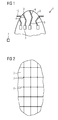
- fig. 1
- is a cross sectional view of an inventive plug;
- fig. 2
- is a plane view of the plug shown in
fig. 1 ; - fig. 3
- shows a method for manufacturing a plug according to the invention; and
- fig. 4
- shows a mould being cured on an inventive plug.
- In
fig. 1 a cross section of a plug 1 is shown. The plug is used for manufacturing a mould for rotor blades. The plug 1 comprises aflexible skin 2 coveringmultiple actuators 3. Theactuators 3 replace a rigid back structure in conventional plugs. Eachactuator 3 comprises anarticulate arm 4 consisting ofsegments 5, 6. In other embodiments an arm may consist of more than two segments, e.g. three or four segments. Allactuators 3 are connected to acontroller 7. Thecontroller 7 is used for adjusting thearticulate arms 4, which can be moved in order to generate a predetermined shape of theflexible skin 2. Theactuators 3 are hydraulic actuators, in other embodiments electric actuators can be used. -
Fig. 2 is a top view of the flexible plug shown infig. 1 . One can see thatmultiple actuators 3 are arranged in a matrix with rows and columns. In the embodiment offig. 2 theflexible skin 2 is formed as amesh 8 which is supported byend sections 9 of theactuators 3. - Specific shapes of the contour of a rotor blade are stored in a memory in the
controller 7. Thecontroller 7 controls theactuators 3 so that eachactuator 3 is moved and adjusted to a specific position so that a predetermined shape of themesh 8 and theflexible skin 2 is generated. In this state aflange 10 is added on the sides of theflexible skin 2 as can be seen infig. 1 . -
Fig. 3 shows the manufacture of the plug 1. Theflexible skin 3 is provided with alateral flange 10. On top of theflexible skin 2 and the flange 10 a vacuum foil 11 is applied. Amould laminate 12 is placed on the vacuum foil 11. Due to the vacuum foil 11 it is not necessary that themesh 8 is air tight. Themould laminate 12 consists of glass fibre reinforced plastics or carbon fibre reinforced plastics. Themould laminate 12 is covered by anothervacuum foil 13. Subsequently themould laminate 12 is cured so that a mould is produced. In this embodiment themould laminate 12 is cured to green strength on theflexible skin 2 of the plug 1. - Subsequently - as shown in
fig. 4 - theflexible skin 2 of plug 1 is used to seal edges around the plug and hot air from aheater 14 is used to fully cure themould laminate 12 so that a mould for the manufacture of rotor blades is created. - In the root of the blade a
heater 14 is set up and hot air is blown into the back structure of the plug 1. In other embodiments a heating means can be built in the flexible skin, e.g. an electric heating. - The plug 1 shown in
fig. 1 to 4 can be used for different mould sizes and both for suction and pressure side, accordingly fewer plug parts are necessary compared to conventional technology. The need for a new plug for a new blade type is eliminated, a new geometry does not require a new plug, instead the current plug is simply loaded with a new CAD file and the actuators are automatically adjusted accordingly. Minor updates of aerodynamic profiles for a blade can be implemented fast by simply uploading a new CAD file for the new shape. The need for mould transportation is reduced or even eliminated as one single plug part can be installed at a blade factory thus eliminating the problems and the risks linked with a long distance transportation. Further the need for plug storage is eliminated. Another advantage is that the aerodynamic design can be frozen much later in a project without effecting the time to market for the new blade design. The manufacture of a mould is possible without a special milling machine being necessary.
Claims (6)
- A plug (1) with a predetermined shape for forming a mould, whereby the plug (1) comprises a flexible skin (2) and multiple actuators (3), wherein the skin (2) covers the multiple actuators (3) which can be adjusted in order to generate the predetermined shape, characterised in that an actuator (3) is formed as an articulated arm with two or more movable articulated segments (5, 6).
- A plug according to claim 1, characterised in that the actuators (3) are arranged in a matrix with rows and columns.
- A plug according to claim 1 or 2, characterised in that an actuator (3) is provided with a shaped end section contacting the flexible skin (2).
- A plug according to any of the preceding claims, characterised in that the flexible skin (2) is an open structure, in particular a mesh (8) or a grid.
- A plug according to any of the preceding claims, characterised in that a controller (7) is provided for controlling the actuators (3) and data for adjusting the actuators (3) is stored in a memory in order to obtain a predetermined shape of the flexible skin (2).
- A plug according to any of the preceding claims, characterised in that it comprises a means for heating the mould, in particular an electric heating or a hot-air heater (14) or a water heating.
Priority Applications (3)
| Application Number | Priority Date | Filing Date | Title |
|---|---|---|---|
| EP11190275.5A EP2596935B1 (en) | 2011-11-23 | 2011-11-23 | Plug and method for manufacturing a plug |
| DK11190275T DK2596935T3 (en) | 2011-11-23 | 2011-11-23 | Plug and Method for producing a plug |
| PL11190275T PL2596935T3 (en) | 2011-11-23 | 2011-11-23 | Plug and method for manufacturing a plug |
Applications Claiming Priority (1)
| Application Number | Priority Date | Filing Date | Title |
|---|---|---|---|
| EP11190275.5A EP2596935B1 (en) | 2011-11-23 | 2011-11-23 | Plug and method for manufacturing a plug |
Publications (2)
| Publication Number | Publication Date |
|---|---|
| EP2596935A1 EP2596935A1 (en) | 2013-05-29 |
| EP2596935B1 true EP2596935B1 (en) | 2015-03-04 |
Family
ID=45315508
Family Applications (1)
| Application Number | Title | Priority Date | Filing Date |
|---|---|---|---|
| EP11190275.5A Active EP2596935B1 (en) | 2011-11-23 | 2011-11-23 | Plug and method for manufacturing a plug |
Country Status (3)
| Country | Link |
|---|---|
| EP (1) | EP2596935B1 (en) |
| DK (1) | DK2596935T3 (en) |
| PL (1) | PL2596935T3 (en) |
Family Cites Families (3)
| Publication number | Priority date | Publication date | Assignee | Title |
|---|---|---|---|---|
| GB2268699B (en) * | 1992-07-16 | 1996-09-18 | British Aerospace | Forming fibre reinforced plastics laminates |
| JPH10328782A (en) * | 1997-05-30 | 1998-12-15 | Toray Eng Co Ltd | Device for manufacturing mold and formation of metallic mold for stretch-forming flat plate |
| WO2006048652A1 (en) * | 2004-11-04 | 2006-05-11 | John Gould | A mould |
-
2011
- 2011-11-23 DK DK11190275T patent/DK2596935T3/en active
- 2011-11-23 PL PL11190275T patent/PL2596935T3/en unknown
- 2011-11-23 EP EP11190275.5A patent/EP2596935B1/en active Active
Also Published As
| Publication number | Publication date |
|---|---|
| PL2596935T3 (en) | 2015-08-31 |
| DK2596935T3 (en) | 2015-03-23 |
| EP2596935A1 (en) | 2013-05-29 |
Similar Documents
| Publication | Publication Date | Title |
|---|---|---|
| JP5860277B2 (en) | Airfoil manufacturing system | |
| DK2814649T3 (en) | DIRECT FORMS FOR WINDERS FOR WIND MILLS, MANUFACTURING PROCEDURE AND APPLICATION OF THE FORM | |
| CN102481706B (en) | Method for making a mould for a wind turbine rotor blade | |
| ES2341828B1 (en) | DEVICE AND PROCEDURE FOR THE MANUFACTURE OF COMPOSITE MATERIAL ELEMENTS. | |
| CN107073757A (en) | The method for manufacturing the mould for wind turbine blade shell | |
| CN102251935B (en) | Blade of a wind turbine | |
| EP2661551B1 (en) | Automated techniques for manufacturing fibrous panels | |
| EP3313638B1 (en) | Method of making a wind turbine blade | |
| EP2653717A1 (en) | Arrangement to retrofit a wind turbine blade | |
| EP2689128B1 (en) | Molding apparatus for making a wind turbine blade and method of making same | |
| EP2228198A1 (en) | A method of strengthening a wind turbine blade and the strengthened blade | |
| JP6971882B2 (en) | Flat composite with layup singularities for molding into 3D shapes | |
| CN105346100A (en) | Method for manufacturing wind power blade crossbeam mold | |
| US12070878B2 (en) | Modular molding units for fabrication of wind turbine blades | |
| EP2380720B1 (en) | An improved wind turbine blade manufacturing arrangement | |
| CN102555115B (en) | For regulating the device of the bottom deformation of the mould of aerodynamics geometry and using the method for moulding of this device | |
| CN113165296A (en) | Improvements relating to wind turbine blade manufacture | |
| AU2013351393B2 (en) | Method for processing a fiber-plastic composite of a rotor blade, semifinished product in the form of a built-up composite, and UV lamp for curing a UV-curable matrix material | |
| DK2596935T3 (en) | Plug and Method for producing a plug | |
| CN111448057B (en) | System and method for manufacturing a reinforced wind turbine blade | |
| CN102615813A (en) | Carbon fiber three-dimensional forming device | |
| WO2007125135A1 (en) | Tool and method for producing wide parts of composite material | |
| US9440408B2 (en) | Method, system and molding tool for manufacturing components from composite fiber materials | |
| CN206520137U (en) | A vulcanizer heating structure | |
| EP3554810B1 (en) | Method for repairing moulded parts using a repair material in the form of a layer |
Legal Events
| Date | Code | Title | Description |
|---|---|---|---|
| PUAI | Public reference made under article 153(3) epc to a published international application that has entered the european phase |
Free format text: ORIGINAL CODE: 0009012 |
|
| AK | Designated contracting states |
Kind code of ref document: A1 Designated state(s): AL AT BE BG CH CY CZ DE DK EE ES FI FR GB GR HR HU IE IS IT LI LT LU LV MC MK MT NL NO PL PT RO RS SE SI SK SM TR |
|
| AX | Request for extension of the european patent |
Extension state: BA ME |
|
| 17P | Request for examination filed |
Effective date: 20130805 |
|
| RBV | Designated contracting states (corrected) |
Designated state(s): AL AT BE BG CH CY CZ DE DK EE ES FI FR GB GR HR HU IE IS IT LI LT LU LV MC MK MT NL NO PL PT RO RS SE SI SK SM TR |
|
| 17Q | First examination report despatched |
Effective date: 20140314 |
|
| GRAP | Despatch of communication of intention to grant a patent |
Free format text: ORIGINAL CODE: EPIDOSNIGR1 |
|
| INTG | Intention to grant announced |
Effective date: 20140924 |
|
| INTG | Intention to grant announced |
Effective date: 20140930 |
|
| GRAS | Grant fee paid |
Free format text: ORIGINAL CODE: EPIDOSNIGR3 |
|
| GRAA | (expected) grant |
Free format text: ORIGINAL CODE: 0009210 |
|
| AK | Designated contracting states |
Kind code of ref document: B1 Designated state(s): AL AT BE BG CH CY CZ DE DK EE ES FI FR GB GR HR HU IE IS IT LI LT LU LV MC MK MT NL NO PL PT RO RS SE SI SK SM TR |
|
| REG | Reference to a national code |
Ref country code: GB Ref legal event code: FG4D |
|
| REG | Reference to a national code |
Ref country code: CH Ref legal event code: EP |
|
| REG | Reference to a national code |
Ref country code: DK Ref legal event code: T3 Effective date: 20150317 |
|
| REG | Reference to a national code |
Ref country code: IE Ref legal event code: FG4D |
|
| REG | Reference to a national code |
Ref country code: AT Ref legal event code: REF Ref document number: 713438 Country of ref document: AT Kind code of ref document: T Effective date: 20150415 |
|
| REG | Reference to a national code |
Ref country code: DE Ref legal event code: R096 Ref document number: 602011014285 Country of ref document: DE Effective date: 20150416 |
|
| REG | Reference to a national code |
Ref country code: AT Ref legal event code: MK05 Ref document number: 713438 Country of ref document: AT Kind code of ref document: T Effective date: 20150304 Ref country code: NL Ref legal event code: VDEP Effective date: 20150304 |
|
| PG25 | Lapsed in a contracting state [announced via postgrant information from national office to epo] |
Ref country code: SE Free format text: LAPSE BECAUSE OF FAILURE TO SUBMIT A TRANSLATION OF THE DESCRIPTION OR TO PAY THE FEE WITHIN THE PRESCRIBED TIME-LIMIT Effective date: 20150304 Ref country code: ES Free format text: LAPSE BECAUSE OF FAILURE TO SUBMIT A TRANSLATION OF THE DESCRIPTION OR TO PAY THE FEE WITHIN THE PRESCRIBED TIME-LIMIT Effective date: 20150304 Ref country code: HR Free format text: LAPSE BECAUSE OF FAILURE TO SUBMIT A TRANSLATION OF THE DESCRIPTION OR TO PAY THE FEE WITHIN THE PRESCRIBED TIME-LIMIT Effective date: 20150304 Ref country code: LT Free format text: LAPSE BECAUSE OF FAILURE TO SUBMIT A TRANSLATION OF THE DESCRIPTION OR TO PAY THE FEE WITHIN THE PRESCRIBED TIME-LIMIT Effective date: 20150304 Ref country code: NO Free format text: LAPSE BECAUSE OF FAILURE TO SUBMIT A TRANSLATION OF THE DESCRIPTION OR TO PAY THE FEE WITHIN THE PRESCRIBED TIME-LIMIT Effective date: 20150604 Ref country code: FI Free format text: LAPSE BECAUSE OF FAILURE TO SUBMIT A TRANSLATION OF THE DESCRIPTION OR TO PAY THE FEE WITHIN THE PRESCRIBED TIME-LIMIT Effective date: 20150304 |
|
| REG | Reference to a national code |
Ref country code: LT Ref legal event code: MG4D |
|
| PG25 | Lapsed in a contracting state [announced via postgrant information from national office to epo] |
Ref country code: LV Free format text: LAPSE BECAUSE OF FAILURE TO SUBMIT A TRANSLATION OF THE DESCRIPTION OR TO PAY THE FEE WITHIN THE PRESCRIBED TIME-LIMIT Effective date: 20150304 Ref country code: AT Free format text: LAPSE BECAUSE OF FAILURE TO SUBMIT A TRANSLATION OF THE DESCRIPTION OR TO PAY THE FEE WITHIN THE PRESCRIBED TIME-LIMIT Effective date: 20150304 Ref country code: RS Free format text: LAPSE BECAUSE OF FAILURE TO SUBMIT A TRANSLATION OF THE DESCRIPTION OR TO PAY THE FEE WITHIN THE PRESCRIBED TIME-LIMIT Effective date: 20150304 Ref country code: GR Free format text: LAPSE BECAUSE OF FAILURE TO SUBMIT A TRANSLATION OF THE DESCRIPTION OR TO PAY THE FEE WITHIN THE PRESCRIBED TIME-LIMIT Effective date: 20150605 |
|
| REG | Reference to a national code |
Ref country code: PL Ref legal event code: T3 |
|
| PG25 | Lapsed in a contracting state [announced via postgrant information from national office to epo] |
Ref country code: NL Free format text: LAPSE BECAUSE OF FAILURE TO SUBMIT A TRANSLATION OF THE DESCRIPTION OR TO PAY THE FEE WITHIN THE PRESCRIBED TIME-LIMIT Effective date: 20150304 |
|
| PG25 | Lapsed in a contracting state [announced via postgrant information from national office to epo] |
Ref country code: PT Free format text: LAPSE BECAUSE OF FAILURE TO SUBMIT A TRANSLATION OF THE DESCRIPTION OR TO PAY THE FEE WITHIN THE PRESCRIBED TIME-LIMIT Effective date: 20150706 Ref country code: EE Free format text: LAPSE BECAUSE OF FAILURE TO SUBMIT A TRANSLATION OF THE DESCRIPTION OR TO PAY THE FEE WITHIN THE PRESCRIBED TIME-LIMIT Effective date: 20150304 Ref country code: SK Free format text: LAPSE BECAUSE OF FAILURE TO SUBMIT A TRANSLATION OF THE DESCRIPTION OR TO PAY THE FEE WITHIN THE PRESCRIBED TIME-LIMIT Effective date: 20150304 Ref country code: RO Free format text: LAPSE BECAUSE OF FAILURE TO SUBMIT A TRANSLATION OF THE DESCRIPTION OR TO PAY THE FEE WITHIN THE PRESCRIBED TIME-LIMIT Effective date: 20150304 Ref country code: CZ Free format text: LAPSE BECAUSE OF FAILURE TO SUBMIT A TRANSLATION OF THE DESCRIPTION OR TO PAY THE FEE WITHIN THE PRESCRIBED TIME-LIMIT Effective date: 20150304 |
|
| REG | Reference to a national code |
Ref country code: FR Ref legal event code: PLFP Year of fee payment: 5 |
|
| PG25 | Lapsed in a contracting state [announced via postgrant information from national office to epo] |
Ref country code: IS Free format text: LAPSE BECAUSE OF FAILURE TO SUBMIT A TRANSLATION OF THE DESCRIPTION OR TO PAY THE FEE WITHIN THE PRESCRIBED TIME-LIMIT Effective date: 20150704 |
|
| REG | Reference to a national code |
Ref country code: DE Ref legal event code: R097 Ref document number: 602011014285 Country of ref document: DE |
|
| PG25 | Lapsed in a contracting state [announced via postgrant information from national office to epo] |
Ref country code: IT Free format text: LAPSE BECAUSE OF FAILURE TO SUBMIT A TRANSLATION OF THE DESCRIPTION OR TO PAY THE FEE WITHIN THE PRESCRIBED TIME-LIMIT Effective date: 20150304 |
|
| PLBE | No opposition filed within time limit |
Free format text: ORIGINAL CODE: 0009261 |
|
| STAA | Information on the status of an ep patent application or granted ep patent |
Free format text: STATUS: NO OPPOSITION FILED WITHIN TIME LIMIT |
|
| 26N | No opposition filed |
Effective date: 20151207 |
|
| PG25 | Lapsed in a contracting state [announced via postgrant information from national office to epo] |
Ref country code: SI Free format text: LAPSE BECAUSE OF FAILURE TO SUBMIT A TRANSLATION OF THE DESCRIPTION OR TO PAY THE FEE WITHIN THE PRESCRIBED TIME-LIMIT Effective date: 20150304 |
|
| PG25 | Lapsed in a contracting state [announced via postgrant information from national office to epo] |
Ref country code: LU Free format text: LAPSE BECAUSE OF FAILURE TO SUBMIT A TRANSLATION OF THE DESCRIPTION OR TO PAY THE FEE WITHIN THE PRESCRIBED TIME-LIMIT Effective date: 20151123 Ref country code: MC Free format text: LAPSE BECAUSE OF FAILURE TO SUBMIT A TRANSLATION OF THE DESCRIPTION OR TO PAY THE FEE WITHIN THE PRESCRIBED TIME-LIMIT Effective date: 20150304 |
|
| REG | Reference to a national code |
Ref country code: CH Ref legal event code: PL |
|
| PG25 | Lapsed in a contracting state [announced via postgrant information from national office to epo] |
Ref country code: LI Free format text: LAPSE BECAUSE OF NON-PAYMENT OF DUE FEES Effective date: 20151130 Ref country code: CH Free format text: LAPSE BECAUSE OF NON-PAYMENT OF DUE FEES Effective date: 20151130 |
|
| REG | Reference to a national code |
Ref country code: IE Ref legal event code: MM4A |
|
| PG25 | Lapsed in a contracting state [announced via postgrant information from national office to epo] |
Ref country code: BE Free format text: LAPSE BECAUSE OF FAILURE TO SUBMIT A TRANSLATION OF THE DESCRIPTION OR TO PAY THE FEE WITHIN THE PRESCRIBED TIME-LIMIT Effective date: 20150304 |
|
| PG25 | Lapsed in a contracting state [announced via postgrant information from national office to epo] |
Ref country code: IE Free format text: LAPSE BECAUSE OF NON-PAYMENT OF DUE FEES Effective date: 20151123 |
|
| REG | Reference to a national code |
Ref country code: FR Ref legal event code: PLFP Year of fee payment: 6 |
|
| PG25 | Lapsed in a contracting state [announced via postgrant information from national office to epo] |
Ref country code: SM Free format text: LAPSE BECAUSE OF FAILURE TO SUBMIT A TRANSLATION OF THE DESCRIPTION OR TO PAY THE FEE WITHIN THE PRESCRIBED TIME-LIMIT Effective date: 20150304 Ref country code: HU Free format text: LAPSE BECAUSE OF FAILURE TO SUBMIT A TRANSLATION OF THE DESCRIPTION OR TO PAY THE FEE WITHIN THE PRESCRIBED TIME-LIMIT; INVALID AB INITIO Effective date: 20111123 Ref country code: BG Free format text: LAPSE BECAUSE OF FAILURE TO SUBMIT A TRANSLATION OF THE DESCRIPTION OR TO PAY THE FEE WITHIN THE PRESCRIBED TIME-LIMIT Effective date: 20150304 |
|
| PG25 | Lapsed in a contracting state [announced via postgrant information from national office to epo] |
Ref country code: CY Free format text: LAPSE BECAUSE OF FAILURE TO SUBMIT A TRANSLATION OF THE DESCRIPTION OR TO PAY THE FEE WITHIN THE PRESCRIBED TIME-LIMIT Effective date: 20150304 |
|
| PG25 | Lapsed in a contracting state [announced via postgrant information from national office to epo] |
Ref country code: MT Free format text: LAPSE BECAUSE OF FAILURE TO SUBMIT A TRANSLATION OF THE DESCRIPTION OR TO PAY THE FEE WITHIN THE PRESCRIBED TIME-LIMIT Effective date: 20150304 |
|
| REG | Reference to a national code |
Ref country code: FR Ref legal event code: PLFP Year of fee payment: 7 |
|
| PG25 | Lapsed in a contracting state [announced via postgrant information from national office to epo] |
Ref country code: MK Free format text: LAPSE BECAUSE OF FAILURE TO SUBMIT A TRANSLATION OF THE DESCRIPTION OR TO PAY THE FEE WITHIN THE PRESCRIBED TIME-LIMIT Effective date: 20150304 Ref country code: TR Free format text: LAPSE BECAUSE OF FAILURE TO SUBMIT A TRANSLATION OF THE DESCRIPTION OR TO PAY THE FEE WITHIN THE PRESCRIBED TIME-LIMIT Effective date: 20150304 |
|
| PG25 | Lapsed in a contracting state [announced via postgrant information from national office to epo] |
Ref country code: AL Free format text: LAPSE BECAUSE OF FAILURE TO SUBMIT A TRANSLATION OF THE DESCRIPTION OR TO PAY THE FEE WITHIN THE PRESCRIBED TIME-LIMIT Effective date: 20150304 |
|
| PGFP | Annual fee paid to national office [announced via postgrant information from national office to epo] |
Ref country code: PL Payment date: 20181113 Year of fee payment: 8 |
|
| REG | Reference to a national code |
Ref country code: DE Ref legal event code: R081 Ref document number: 602011014285 Country of ref document: DE Owner name: SIEMENS GAMESA RENEWABLE ENERGY A/S, DK Free format text: FORMER OWNER: SIEMENS AKTIENGESELLSCHAFT, 80333 MUENCHEN, DE |
|
| REG | Reference to a national code |
Ref country code: GB Ref legal event code: 732E Free format text: REGISTERED BETWEEN 20191128 AND 20191204 |
|
| PG25 | Lapsed in a contracting state [announced via postgrant information from national office to epo] |
Ref country code: PL Free format text: LAPSE BECAUSE OF NON-PAYMENT OF DUE FEES Effective date: 20191123 |
|
| PGFP | Annual fee paid to national office [announced via postgrant information from national office to epo] |
Ref country code: FR Payment date: 20241126 Year of fee payment: 14 |
|
| PGFP | Annual fee paid to national office [announced via postgrant information from national office to epo] |
Ref country code: DK Payment date: 20250901 Year of fee payment: 15 |
|
| PGFP | Annual fee paid to national office [announced via postgrant information from national office to epo] |
Ref country code: GB Payment date: 20250901 Year of fee payment: 15 |
|
| PGFP | Annual fee paid to national office [announced via postgrant information from national office to epo] |
Ref country code: DE Payment date: 20250731 Year of fee payment: 15 |