EP2596849A1 - Method of removing a gaseous contaminant, preferably H2S, from a contaminated gas stream - Google Patents
Method of removing a gaseous contaminant, preferably H2S, from a contaminated gas stream Download PDFInfo
- Publication number
- EP2596849A1 EP2596849A1 EP11190454.6A EP11190454A EP2596849A1 EP 2596849 A1 EP2596849 A1 EP 2596849A1 EP 11190454 A EP11190454 A EP 11190454A EP 2596849 A1 EP2596849 A1 EP 2596849A1
- Authority
- EP
- European Patent Office
- Prior art keywords
- gas stream
- contaminated gas
- stream
- vessel
- contaminant
- Prior art date
- Legal status (The legal status is an assumption and is not a legal conclusion. Google has not performed a legal analysis and makes no representation as to the accuracy of the status listed.)
- Withdrawn
Links
Images
Classifications
-
- B—PERFORMING OPERATIONS; TRANSPORTING
- B01—PHYSICAL OR CHEMICAL PROCESSES OR APPARATUS IN GENERAL
- B01D—SEPARATION
- B01D53/00—Separation of gases or vapours; Recovering vapours of volatile solvents from gases; Chemical or biological purification of waste gases, e.g. engine exhaust gases, smoke, fumes, flue gases, aerosols
- B01D53/14—Separation of gases or vapours; Recovering vapours of volatile solvents from gases; Chemical or biological purification of waste gases, e.g. engine exhaust gases, smoke, fumes, flue gases, aerosols by absorption
- B01D53/1456—Removing acid components
- B01D53/1468—Removing hydrogen sulfide
-
- B—PERFORMING OPERATIONS; TRANSPORTING
- B01—PHYSICAL OR CHEMICAL PROCESSES OR APPARATUS IN GENERAL
- B01D—SEPARATION
- B01D53/00—Separation of gases or vapours; Recovering vapours of volatile solvents from gases; Chemical or biological purification of waste gases, e.g. engine exhaust gases, smoke, fumes, flue gases, aerosols
- B01D53/14—Separation of gases or vapours; Recovering vapours of volatile solvents from gases; Chemical or biological purification of waste gases, e.g. engine exhaust gases, smoke, fumes, flue gases, aerosols by absorption
- B01D53/1456—Removing acid components
- B01D53/1475—Removing carbon dioxide
-
- C—CHEMISTRY; METALLURGY
- C10—PETROLEUM, GAS OR COKE INDUSTRIES; TECHNICAL GASES CONTAINING CARBON MONOXIDE; FUELS; LUBRICANTS; PEAT
- C10L—FUELS NOT OTHERWISE PROVIDED FOR; NATURAL GAS; SYNTHETIC NATURAL GAS OBTAINED BY PROCESSES NOT COVERED BY SUBCLASSES C10G OR C10K; LIQUIFIED PETROLEUM GAS; USE OF ADDITIVES TO FUELS OR FIRES; FIRE-LIGHTERS
- C10L3/00—Gaseous fuels; Natural gas; Synthetic natural gas obtained by processes not covered by subclass C10G, C10K; Liquefied petroleum gas
- C10L3/06—Natural gas; Synthetic natural gas obtained by processes not covered by C10G, C10K3/02 or C10K3/04
- C10L3/10—Working-up natural gas or synthetic natural gas
- C10L3/101—Removal of contaminants
- C10L3/102—Removal of contaminants of acid contaminants
- C10L3/103—Sulfur containing contaminants
-
- C—CHEMISTRY; METALLURGY
- C10—PETROLEUM, GAS OR COKE INDUSTRIES; TECHNICAL GASES CONTAINING CARBON MONOXIDE; FUELS; LUBRICANTS; PEAT
- C10L—FUELS NOT OTHERWISE PROVIDED FOR; NATURAL GAS; SYNTHETIC NATURAL GAS OBTAINED BY PROCESSES NOT COVERED BY SUBCLASSES C10G OR C10K; LIQUIFIED PETROLEUM GAS; USE OF ADDITIVES TO FUELS OR FIRES; FIRE-LIGHTERS
- C10L3/00—Gaseous fuels; Natural gas; Synthetic natural gas obtained by processes not covered by subclass C10G, C10K; Liquefied petroleum gas
- C10L3/06—Natural gas; Synthetic natural gas obtained by processes not covered by C10G, C10K3/02 or C10K3/04
- C10L3/10—Working-up natural gas or synthetic natural gas
- C10L3/108—Production of gas hydrates
-
- B—PERFORMING OPERATIONS; TRANSPORTING
- B01—PHYSICAL OR CHEMICAL PROCESSES OR APPARATUS IN GENERAL
- B01D—SEPARATION
- B01D2252/00—Absorbents, i.e. solvents and liquid materials for gas absorption
- B01D2252/10—Inorganic absorbents
- B01D2252/103—Water
-
- B—PERFORMING OPERATIONS; TRANSPORTING
- B01—PHYSICAL OR CHEMICAL PROCESSES OR APPARATUS IN GENERAL
- B01D—SEPARATION
- B01D2252/00—Absorbents, i.e. solvents and liquid materials for gas absorption
- B01D2252/60—Additives
- B01D2252/602—Activators, promoting agents, catalytic agents or enzymes
-
- B—PERFORMING OPERATIONS; TRANSPORTING
- B01—PHYSICAL OR CHEMICAL PROCESSES OR APPARATUS IN GENERAL
- B01D—SEPARATION
- B01D2256/00—Main component in the product gas stream after treatment
- B01D2256/24—Hydrocarbons
- B01D2256/245—Methane
-
- B—PERFORMING OPERATIONS; TRANSPORTING
- B01—PHYSICAL OR CHEMICAL PROCESSES OR APPARATUS IN GENERAL
- B01D—SEPARATION
- B01D2257/00—Components to be removed
- B01D2257/30—Sulfur compounds
- B01D2257/304—Hydrogen sulfide
-
- B—PERFORMING OPERATIONS; TRANSPORTING
- B01—PHYSICAL OR CHEMICAL PROCESSES OR APPARATUS IN GENERAL
- B01D—SEPARATION
- B01D2257/00—Components to be removed
- B01D2257/30—Sulfur compounds
- B01D2257/306—Organic sulfur compounds, e.g. mercaptans
-
- B—PERFORMING OPERATIONS; TRANSPORTING
- B01—PHYSICAL OR CHEMICAL PROCESSES OR APPARATUS IN GENERAL
- B01D—SEPARATION
- B01D2257/00—Components to be removed
- B01D2257/30—Sulfur compounds
- B01D2257/308—Carbonoxysulfide COS
-
- B—PERFORMING OPERATIONS; TRANSPORTING
- B01—PHYSICAL OR CHEMICAL PROCESSES OR APPARATUS IN GENERAL
- B01D—SEPARATION
- B01D2257/00—Components to be removed
- B01D2257/50—Carbon oxides
- B01D2257/504—Carbon dioxide
-
- Y—GENERAL TAGGING OF NEW TECHNOLOGICAL DEVELOPMENTS; GENERAL TAGGING OF CROSS-SECTIONAL TECHNOLOGIES SPANNING OVER SEVERAL SECTIONS OF THE IPC; TECHNICAL SUBJECTS COVERED BY FORMER USPC CROSS-REFERENCE ART COLLECTIONS [XRACs] AND DIGESTS
- Y02—TECHNOLOGIES OR APPLICATIONS FOR MITIGATION OR ADAPTATION AGAINST CLIMATE CHANGE
- Y02C—CAPTURE, STORAGE, SEQUESTRATION OR DISPOSAL OF GREENHOUSE GASES [GHG]
- Y02C20/00—Capture or disposal of greenhouse gases
- Y02C20/40—Capture or disposal of greenhouse gases of CO2
Definitions
- the present invention relates to a method of removing a gaseous contaminant, preferably hydrogen sulphide (H 2 S), from a contaminated gas stream.
- a gaseous contaminant preferably hydrogen sulphide (H 2 S)
- the present invention relates to a method of removing a gaseous contaminant wherein hydrates of the contaminant, in particular H 2 S, are formed.
- Natural gas may contain various undesired contaminants, the most prominent ones being hydrogen sulphide (H 2 S) and carbon dioxide (CO 2 ), other contaminants being for example carbonyl sulphide (COS), mercaptans, alkyl sulphides and aromatic sulphur-containing compounds.
- Transport and/or treatment of natural gas that contains these contaminants may add to the costs of the transport and/or treatment.
- the contaminants may also prove corrosive, hydrogen sulphide is toxic and on combustion produces sulphur dioxide, another pollutant.
- carbon dioxide reduces the heating value of natural gas. It is therefore desirable to remove these contaminants from the natural gas at an early stage.
- WO 2010/018609 An example of a method of removing a contaminant such as H 2 S and CO 2 from natural gas using hydrate formation has been described in WO 2010/018609 .
- a problem of the method as described in WO 2010/018609 is that it is rather complicated; also, a significant amount of methane-hydrates are formed, which need to be selectively decomposed.
- a further problem of WO 2010/018609 is that methane- and H 2 S-hydrates are formed simultaneously; i.e. mixed hydrates are formed which need to be dissociated subsequently in a controlled manner.
- a gaseous contaminant preferably H 2 S
- One of the above or other objects may be achieved by the present invention by providing a method of removing a gaseous contaminant, preferably hydrogen sulphide (H 2 S), from a contaminated gas stream, the method comprising at least the steps of:
- a gaseous contaminant preferably hydrogen sulphide (H 2 S)
- gaseous contaminants such as in particular H 2 S can be efficiently removed from a contaminated gas stream being contaminated with said contaminants.
- a further advantage of the method according to the present invention is that it can be performed at relatively high temperatures. Also, the method according to the present invention can be perfomed relatively quickly; this, as the (in particular H 2 S) hydrate formation occurs within a couple of minutes. Further, the method according to the present invention can be performed using simple equipment.
- the contaminated gas stream as provided in step (a) may be any stream, but is preferably rich in aliphatic hydrocarbons (such as methane, ethane, propane, butane and pentane). More particularly, the contaminated gas stream is a methane-rich stream such as natural gas, an associated gas stream or a coal bed methane stream. Typically, the contaminated gas stream contains from 10 to 95 vol.% methane, preferably at least 50 vol.% methane. Usually, the contaminated gas stream may contain from 0.1 to 20 vol.%, preferably from 0.1 to 10 vol.%, of C 2 -C 6 or higher aliphatic hydrocarbon compounds.
- the contaminated gas stream may comprise up to 20 vol.%, suitably from 0.1 to 10 vol.% of nitrogen.
- the contaminated gas stream may comprise other (non-aliphatic-hydrocarbon) contaminants such as hydrogen sulphide (H 2 S), carbon dioxide (CO 2 ), carbonyl sulphide (COS), mercaptans, alkyl sulphides and aromatic sulphur-containing compounds (such as thiophenes).
- the main contaminant to be removed is H 2 S.
- the amount of H 2 S in the contaminated gas stream as provided in step (a) is suitably from 1 ppmv to 80 vol.%.
- the contaminated gas stream provided in step (a) contains at least 5 vol.%, preferably at least 10 vol.%, more preferably at least 15 vol.% H 2 S, based on the contaminated gas stream.
- step (b) the contaminated gas stream is fed into a vessel and mixed with an aqueous liquid contained in said vessel, thereby forming hydrates of the contaminant.
- the vessel as used in the present invention is not limited in any way and may be selected from a wide range of vessels.
- the aqueous liquid may be any aqueous liquid that allows the formation of hydrates. Typically, the aqueous liquid contains at least 85 vol.% and less than 99 vol.% water. The aqueous liquid may have various salt contents. Also, if desired, the aqueous liquid may contain hydrate formation promoting agents such as quaternary ammonium salts or the like; these agents may be added separately.
- the aqueous liquid contains before the mixing of the contaminated gas stream in step (b) at least 0.1 wt.% solvated gaseous contaminant.
- the aqueous liquid is pre-saturated and already contains gaseous contaminant solvated in the aqueous liquid to assist the hydrate formation.
- the person skilled in the art will readily understand how to calculate the saturation level of the solvated gaseous contaminant in the aqueous liquid.
- the contaminant is H 2 S
- an ion-selective electrode may be used to detect sulphide ion in water as described in ASTM D4658-92, followed by back-calculation from the known dissociation equilibrium constants of H 2 S.
- the aqueous liquid contains, before mixing in step (b), at least 0.2 wt.%, preferably at least 0.3 wt.%, more preferably at least 0.5 wt.%, even more preferably at least 1.0 wt.% solvated gaseous contaminant.
- the aqueous liquid contains less than 15.0 wt.%, preferably less than 9.0 wt.% solvated gaseous contaminant, most preferably the aqueous liquid contains from 3.0 to 5.0 wt.%, such as 4.0 wt.%, solvated gaseous contaminant.
- the mixing of the contaminated gas stream with the aqueous liquid may be performed in various ways. Preferably, the mixing take place such that rapid gas/liquid contacting is obtained. As one example, a suction stirrer for rapid gas/liquid mixing may be used. As another example, dispersion of the aqueous solution as fine droplets into the contaminated gas may be performed.
- the contaminated gas is mixed with the aqueous liquid, by introducing the contaminated gas stream as gas bubbles in the aqueous solution.
- the gas bubbles have a bubble size of less than 5 mm, preferably less than 4 mm, more preferably less than 3 mm and typically above 0.1 mm.
- the gas bubble surface to volume ratio is at least 1000, preferably at least 5000.
- these gas bubbles can be obtained in various ways, such as by using stirring, mixing, and the like.
- the mixing is performed using high speed mixing using e.g. a vacuum gas stirrer.
- the pressure in the vessel is from 5 to 50 bara, preferably from 10 to 40 bara, more preferably from 25 to 40 bara.
- the temperature in the vessel is from 1 to 30°C, preferably from 5 to 20°C, more preferably from 10 to 16°C.
- a contaminant-depleted gas stream is removed from the vessel.
- this contaminant-depleted gas stream is a methane-rich stream which may be subjected to further process steps, if desired, e.g. to remove other contaminants.
- the contaminated gas stream as provided in step (a) is natural gas or the like
- the contaminant-depleted gas stream as removed in step (c) may e.g. be liquefied to obtain LNG.
- a stream containing hydrates as formed in step (b) is removed from the vessel.
- the stream containing hydrates as removed in step (d) is in the form of a slurry containing from 10 to 60 wt.% solids, preferably from 20 to 50 wt.% solids.
- the slurry typically comprises H 2 S hydrates in a solid dispersion suspended in an aqueous medium.
- the stream removed in step (d) may be subjected to further process steps, if desired.
- the slurry may be subjected to a solid/liquid separation (using conventional techniques such as a centrifugal system with solid retaining filter walls, a filtration step, etc.). If desired, the slurry may be subjected to an intermediate particle size reduction step (using e.g. milled crushing).
- the ratio of the partial pressure of the gaseous CH 4 before and after the hydrates formation in step (b) is preferably kept below 0.10, preferably below 0.05 in order to avoid the formation of CH 4 hydrates.
- the contact time between the contaminated gas stream and the aqueous liquid in the vessel is preferably kept short, typically below 10 minutes, preferably below 5 minutes.
- the hydrates in the stream containing hydrates as removed in step (d) are decomposed (e.g. in a further vessel) thereby obtaining a stream containing an aqueous solution of the gaseous contaminant; preferably, the aqueous solution (as possibly obtained in the further vessel) is a saturated solution of the gaseous contaminant. It is even more preferred that the stream containing the aqueous solution of the gaseous contaminant is used as the aqueous liquid in step (b). To this end, the aqueous solution is recycled to step (b).
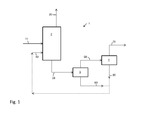
- FIG. 1 a process scheme is shown, generally referred to with reference number 1, comprising a first vessel 2, a second vessel 3 and a third vessel 4.
- H 2 S is removed from a contaminated CH 4 gas stream 10 (containing gaseous H 2 S as contaminant).
- the contaminated gas stream 10 is fed into the vessel 2.
- the vessel 2 contains an aqueous liquid (fed as stream 40), containing an aqueous solution of H 2 S in water.
- the aqueous solution is saturated in H 2 S, containing e.g. 0.5 wt.% solvated gaseous contaminant.
- the contaminated gas stream 10 is dispersed into the aqueous liquid, e.g. by providing gas bubbles of the contaminated gas in the aqueous liquid having a bubble size of less than 5 mm. These bubbles can be achieved by using e.g. high speed mixing.
- H 2 S hydrates are formed in the vessel 2.
- the contact time in the vessel 2 is kept relatively short, preferably below 3 minutes.
- a H 2 S-depleted CH 4 rich gas stream 20 is removed from the vessel 2; stream 20 may be subjected to further steps and e.g. be liquefied to obtain LNG.
- a stream 30 containing a slurry of hydrates in water is removed from the vessel 2.
- the slurry stream 30 is sent to and fed into the second vessel 3 (functioning as a solid/liquid separator) to separate the H 2 S hydrates from the water.
- a concentrated H 2 S hydrates stream is removed from the vessel 3 as stream 50.
- a water-enriched stream 60 (still containing some dissolved H 2 S) is removed from the vessel 3.
- the concentrated H 2 S hydrates stream 50 is sent to the vessel 4 to decompose the H 2 S hydrates.
- a gaseous H 2 S stream 70 is removed, as well as a liquid stream 80, stream 80 being an (preferably saturated) aqueous solution of H 2 S.
- stream 80 is an (preferably saturated) aqueous solution of H 2 S.
- at least a part of the stream 80 and/or stream 60 may be reused (after optionally combining if at least a part of both stream 60 and 80 is reused) as stream 40 in vessel 2.
- Table 1 below shows typical conditions and compositions of some of the streams in the process scheme 1.
- Table 1 Stream Pressure [bara] Temperature [°C] Composition 10 40 15 CH 4 (g) + H 2 S(g) 20 40 15 CH 4 (g) 30 40 15 H 2 O(l) + H 2 S(aq) + H 2 S(hydrate) 40 35 15 H 2 O(l) + H 2 S(aq) 50 15 H 2 S(hydrate) 60 35 15 H 2 O(l) + H 2 S(aq) 70 15 H 2 S(g) 80 15 H 2 S(l) + H 2 S(aq)
- Example 1 The method of Example 1 was repeated, except that 27 g of brine (containing 3 wt.% NaCl) saturated with H 2 S (again, containing 0.5 wt.% solvated H 2 S) was used. Further, the applied inlet pressure to the autoclave was 27 bara and the temperature of the autoclave was 5°C.
Landscapes
- Chemical & Material Sciences (AREA)
- Oil, Petroleum & Natural Gas (AREA)
- Engineering & Computer Science (AREA)
- General Chemical & Material Sciences (AREA)
- Chemical Kinetics & Catalysis (AREA)
- Analytical Chemistry (AREA)
- Organic Chemistry (AREA)
- Gas Separation By Absorption (AREA)
Abstract
The invention provides a method of removing a gaseous contaminant, preferably hydrogen sulphide (H2S), from a contaminated gas stream, the method comprising at least the steps of:
(a) providing a contaminated gas stream (10) containing a gaseous contaminant;
(b) mixing the contaminated gas stream with an aqueous liquid (40) in a vessel (2) thereby forming hydrates of the contaminant;
(c) removing a contaminant-depleted gas stream (20) from the vessel;
(d) removing a stream (30) containing hydrates as formed in step (b) from the vessel;
wherein the aqueous liquid before the mixing of the contaminated gas stream in step (b) contains at least 0.1 wt.% solvated gaseous contaminant.
(a) providing a contaminated gas stream (10) containing a gaseous contaminant;
(b) mixing the contaminated gas stream with an aqueous liquid (40) in a vessel (2) thereby forming hydrates of the contaminant;
(c) removing a contaminant-depleted gas stream (20) from the vessel;
(d) removing a stream (30) containing hydrates as formed in step (b) from the vessel;
wherein the aqueous liquid before the mixing of the contaminated gas stream in step (b) contains at least 0.1 wt.% solvated gaseous contaminant.
Description
- The present invention relates to a method of removing a gaseous contaminant, preferably hydrogen sulphide (H2S), from a contaminated gas stream. In particular, the present invention relates to a method of removing a gaseous contaminant wherein hydrates of the contaminant, in particular H2S, are formed.
- Natural gas may contain various undesired contaminants, the most prominent ones being hydrogen sulphide (H2S) and carbon dioxide (CO2), other contaminants being for example carbonyl sulphide (COS), mercaptans, alkyl sulphides and aromatic sulphur-containing compounds. Transport and/or treatment of natural gas that contains these contaminants may add to the costs of the transport and/or treatment. The contaminants may also prove corrosive, hydrogen sulphide is toxic and on combustion produces sulphur dioxide, another pollutant. Moreover, carbon dioxide reduces the heating value of natural gas. It is therefore desirable to remove these contaminants from the natural gas at an early stage. Several methods to remove the above contaminants have been described in the prior art.
- An example of a method of removing a contaminant such as H2S and CO2 from natural gas using hydrate formation has been described in
WO 2010/018609 . A problem of the method as described inWO 2010/018609 is that it is rather complicated; also, a significant amount of methane-hydrates are formed, which need to be selectively decomposed. A further problem ofWO 2010/018609 is that methane- and H2S-hydrates are formed simultaneously; i.e. mixed hydrates are formed which need to be dissociated subsequently in a controlled manner. - It is an object of the present invention to avoid one or more of the above problems. It is a further object of the present invention to provide an alternative method of removing a gaseous contaminant, preferably H2S, from a contaminated gas stream such as natural gas.
- One of the above or other objects may be achieved by the present invention by providing a method of removing a gaseous contaminant, preferably hydrogen sulphide (H2S), from a contaminated gas stream, the method comprising at least the steps of:
- (a) providing a contaminated gas stream containing a gaseous contaminant;
- (b) mixing the contaminated gas stream with an aqueous liquid in a vessel thereby forming hydrates of the contaminant;
- (c) removing a contaminant-depleted gas stream from the vessel;
- (d) removing a stream containing hydrates as formed in step (b) from the vessel;
- It has now been surprisingly found that, using the method according to the present invention, gaseous contaminants such as in particular H2S can be efficiently removed from a contaminated gas stream being contaminated with said contaminants.
- A further advantage of the method according to the present invention is that it can be performed at relatively high temperatures. Also, the method according to the present invention can be perfomed relatively quickly; this, as the (in particular H2S) hydrate formation occurs within a couple of minutes. Further, the method according to the present invention can be performed using simple equipment.
- The contaminated gas stream as provided in step (a) may be any stream, but is preferably rich in aliphatic hydrocarbons (such as methane, ethane, propane, butane and pentane). More particularly, the contaminated gas stream is a methane-rich stream such as natural gas, an associated gas stream or a coal bed methane stream. Typically, the contaminated gas stream contains from 10 to 95 vol.% methane, preferably at least 50 vol.% methane. Usually, the contaminated gas stream may contain from 0.1 to 20 vol.%, preferably from 0.1 to 10 vol.%, of C2-C6 or higher aliphatic hydrocarbon compounds. Also, the contaminated gas stream may comprise up to 20 vol.%, suitably from 0.1 to 10 vol.% of nitrogen. The contaminated gas stream may comprise other (non-aliphatic-hydrocarbon) contaminants such as hydrogen sulphide (H2S), carbon dioxide (CO2), carbonyl sulphide (COS), mercaptans, alkyl sulphides and aromatic sulphur-containing compounds (such as thiophenes).
- Although the above or other contaminants may be removed from a contaminated gas stream using the method according to the present invention, it is particularly preferred that the main contaminant to be removed is H2S. To this end, the amount of H2S in the contaminated gas stream as provided in step (a) is suitably from 1 ppmv to 80 vol.%. Preferably the contaminated gas stream provided in step (a) contains at least 5 vol.%, preferably at least 10 vol.%, more preferably at least 15 vol.% H2S, based on the contaminated gas stream.
- In step (b), the contaminated gas stream is fed into a vessel and mixed with an aqueous liquid contained in said vessel, thereby forming hydrates of the contaminant.
- The vessel as used in the present invention is not limited in any way and may be selected from a wide range of vessels.
- The aqueous liquid may be any aqueous liquid that allows the formation of hydrates. Typically, the aqueous liquid contains at least 85 vol.% and less than 99 vol.% water. The aqueous liquid may have various salt contents. Also, if desired, the aqueous liquid may contain hydrate formation promoting agents such as quaternary ammonium salts or the like; these agents may be added separately.
- As mentioned above, the aqueous liquid contains before the mixing of the contaminated gas stream in step (b) at least 0.1 wt.% solvated gaseous contaminant. Hence, the aqueous liquid is pre-saturated and already contains gaseous contaminant solvated in the aqueous liquid to assist the hydrate formation. The person skilled in the art will readily understand how to calculate the saturation level of the solvated gaseous contaminant in the aqueous liquid. As an example, if the contaminant is H2S, an ion-selective electrode may be used to detect sulphide ion in water as described in ASTM D4658-92, followed by back-calculation from the known dissociation equilibrium constants of H2S.
- According to a preferred embodiment according to the present invention, the aqueous liquid contains, before mixing in step (b), at least 0.2 wt.%, preferably at least 0.3 wt.%, more preferably at least 0.5 wt.%, even more preferably at least 1.0 wt.% solvated gaseous contaminant. Typically the aqueous liquid contains less than 15.0 wt.%, preferably less than 9.0 wt.% solvated gaseous contaminant, most preferably the aqueous liquid contains from 3.0 to 5.0 wt.%, such as 4.0 wt.%, solvated gaseous contaminant.
- The person skilled in the art will readily understand that the mixing of the contaminated gas stream with the aqueous liquid may be performed in various ways. Preferably, the mixing take place such that rapid gas/liquid contacting is obtained. As one example, a suction stirrer for rapid gas/liquid mixing may be used. As another example, dispersion of the aqueous solution as fine droplets into the contaminated gas may be performed.
- Preferably, in step (b) the contaminated gas is mixed with the aqueous liquid, by introducing the contaminated gas stream as gas bubbles in the aqueous solution. Preferably, the gas bubbles have a bubble size of less than 5 mm, preferably less than 4 mm, more preferably less than 3 mm and typically above 0.1 mm. Preferably, during the introducing the gas bubbles in step (b) the gas bubble surface to volume ratio is at least 1000, preferably at least 5000. Again, these gas bubbles can be obtained in various ways, such as by using stirring, mixing, and the like. Preferably, the mixing is performed using high speed mixing using e.g. a vacuum gas stirrer.
- Although the conditions during the mixing in step (b) can be varied in many ways, it is preferred that during the mixing in step (b) the pressure in the vessel is from 5 to 50 bara, preferably from 10 to 40 bara, more preferably from 25 to 40 bara. Also, it is preferred that during the mixing in step (b) the temperature in the vessel is from 1 to 30°C, preferably from 5 to 20°C, more preferably from 10 to 16°C.
- In step (c), a contaminant-depleted gas stream is removed from the vessel. Typically this contaminant-depleted gas stream is a methane-rich stream which may be subjected to further process steps, if desired, e.g. to remove other contaminants. In case the contaminated gas stream as provided in step (a) is natural gas or the like, the contaminant-depleted gas stream as removed in step (c) may e.g. be liquefied to obtain LNG.
- In step (d), a stream containing hydrates as formed in step (b) is removed from the vessel. Typically, the stream containing hydrates as removed in step (d) is in the form of a slurry containing from 10 to 60 wt.% solids, preferably from 20 to 50 wt.% solids. In case the contaminant is H2S, the slurry typically comprises H2S hydrates in a solid dispersion suspended in an aqueous medium. The stream removed in step (d) may be subjected to further process steps, if desired. As an example, the slurry may be subjected to a solid/liquid separation (using conventional techniques such as a centrifugal system with solid retaining filter walls, a filtration step, etc.). If desired, the slurry may be subjected to an intermediate particle size reduction step (using e.g. milled crushing).
- In case the contaminated gas stream as provided in step (a) contains gaseous CH4, the ratio of the partial pressure of the gaseous CH4 before and after the hydrates formation in step (b) (i.e. partial pressure of the gaseous CH4 before the hydrates formation divided by the partial pressure of the gaseous CH4 after the hydrates formation) is preferably kept below 0.10, preferably below 0.05 in order to avoid the formation of CH4 hydrates. To this end, the contact time between the contaminated gas stream and the aqueous liquid in the vessel is preferably kept short, typically below 10 minutes, preferably below 5 minutes.
- According to a particularly preferred embodiment of the present invention, the hydrates in the stream containing hydrates as removed in step (d) are decomposed (e.g. in a further vessel) thereby obtaining a stream containing an aqueous solution of the gaseous contaminant; preferably, the aqueous solution (as possibly obtained in the further vessel) is a saturated solution of the gaseous contaminant. It is even more preferred that the stream containing the aqueous solution of the gaseous contaminant is used as the aqueous liquid in step (b). To this end, the aqueous solution is recycled to step (b).
- Hereinafter the invention will be further illustrated by the following non-limiting drawing. Herein shows:
-
Fig. 1 schematically a process scheme of the method according to the present invention. - For the purpose of this description a single reference number will be assigned to a line as well as a stream carried in that line. Same reference numbers refer to same or similar elements.
- In
Figure 1 a process scheme is shown, generally referred to withreference number 1, comprising afirst vessel 2, asecond vessel 3 and athird vessel 4. In theprocess scheme 1, H2S is removed from a contaminated CH4 gas stream 10 (containing gaseous H2S as contaminant). - The contaminated
gas stream 10 is fed into thevessel 2. Thevessel 2 contains an aqueous liquid (fed as stream 40), containing an aqueous solution of H2S in water. The aqueous solution is saturated in H2S, containing e.g. 0.5 wt.% solvated gaseous contaminant. The contaminatedgas stream 10 is dispersed into the aqueous liquid, e.g. by providing gas bubbles of the contaminated gas in the aqueous liquid having a bubble size of less than 5 mm. These bubbles can be achieved by using e.g. high speed mixing. Hereby H2S hydrates are formed in thevessel 2. In order to avoid the formation of CH4 hydrates, the contact time in thevessel 2 is kept relatively short, preferably below 3 minutes. - Subsequently, a H2S-depleted CH4
rich gas stream 20 is removed from thevessel 2;stream 20 may be subjected to further steps and e.g. be liquefied to obtain LNG. - Typically at the bottom of the vessel 2 a
stream 30 containing a slurry of hydrates in water is removed from thevessel 2. Theslurry stream 30 is sent to and fed into the second vessel 3 (functioning as a solid/liquid separator) to separate the H2S hydrates from the water. A concentrated H2S hydrates stream is removed from thevessel 3 asstream 50. Also, a water-enriched stream 60 (still containing some dissolved H2S) is removed from thevessel 3. - The concentrated H2S hydrates
stream 50 is sent to thevessel 4 to decompose the H2S hydrates. As the person skilled in the art is familiar with how to decompose hydrates, this is not further explained here. From the vessel 4 a gaseous H2S stream 70 is removed, as well as aliquid stream 80,stream 80 being an (preferably saturated) aqueous solution of H2S. As suggested in the embodiment ofFigure 1 , at least a part of thestream 80 and/orstream 60 may be reused (after optionally combining if at least a part of bothstream stream 40 invessel 2. - Table 1 below shows typical conditions and compositions of some of the streams in the
process scheme 1.Table 1 Stream Pressure [bara] Temperature [°C] Composition 10 40 15 CH4(g) + H2S(g) 20 40 15 CH4(g) 30 40 15 H2O(l) + H2S(aq) + H2S(hydrate) 40 35 15 H2O(l) + H2S(aq) 50 15 H2S(hydrate) 60 35 15 H2O(l) + H2S(aq) 70 15 H2S(g) 80 15 H2S(l) + H2S(aq) - The invention will be illustrated using the following, non-limiting, examples.
- In an 308 ml Hatsalloy C autoclave (obtainable from Premex reactor A.G. (Langnau, Switzerland)) containing 27 g of distilled water saturated with H2S (containing 0.5 wt.% solvated H2S), a contaminated gas mixture consisting of 70 vol.% methane and 30 vol.% H2S was added via a high speed gas injection stirrer (model BR2; obtainable from Premex reactor A.G.) rotating at >1000 rpm thereby providing gas bubbles of the contaminated gas in the distilled water saturated with H2S having a bubble size of less than 5 mm. The applied inlet pressure to the autoclave was 31 bara and the temperature of the autoclave was 15°C. After three minutes, the formation of H2S hydrate crystals was observed. The gas stream removed from the autoclave had an H2S concentration of 22 vol.%.
- The method of Example 1 was repeated, except that 27 g of brine (containing 3 wt.% NaCl) saturated with H2S (again, containing 0.5 wt.% solvated H2S) was used. Further, the applied inlet pressure to the autoclave was 27 bara and the temperature of the autoclave was 5°C.
- Within 1 minute, the formation of H2S hydrate crystals was observed. The gas stream removed from the autoclave had an H2S concentration of 22 vol.%.
- As can be seen from Examples 1 and 2, the H2S levels in the contaminated gas stream were significantly reduced using the method according to the present invention.
Claims (12)
- A method of removing a gaseous contaminant, preferably hydrogen sulphide (H2S), from a contaminated gas stream, the method comprising at least the steps of:(a) providing a contaminated gas stream containing a gaseous contaminant;(b) mixing the contaminated gas stream with an aqueous liquid in a vessel thereby forming hydrates of the contaminant;(c) removing a contaminant-depleted gas stream from the vessel;(d) removing a stream containing hydrates as formed in step (b) from the vessel;
wherein the aqueous liquid before the mixing of the contaminated gas stream in step (b) contains at least 0.1 wt.% solvated gaseous contaminant. - A method according to claim 1, wherein the contaminated gas stream provided in step (a) contains at least 5 vol.%, preferably at least 10 vol.%, more preferably at least 15 vol.% H2S as the gaseous contaminant.
- A method according to claim 1 or 2, wherein before the mixing in step (b) the aqueous liquid contains at least 0.2 wt.%, preferably at least 0.3 wt.% solvated gaseous contaminant.
- A method according to any one of claims 1-3, wherein in step (b) the contaminated gas stream is mixed with the aqueous liquid, by introducing the contaminated gas stream as gas bubbles.
- A method according to claim 4, wherein during the introducing in step (b) the gas bubble surface to volume ratio is at least 1000, preferably at least 5000.
- A method according to any one of claims 1-5, wherein during the mixing in step (b) the pressure in the vessel is from 5 to 50 bara, preferably from 10 to 40 bara, more preferably from 25 to 40 bara.
- A method according to any one of claims 1-6, wherein during the mixing in step (b) the temperature in the vessel is from 1 to 30°C, preferably from 5 to 20°C, more preferably from 10 to 16°C.
- A method according to any one of claims 1-7, wherein the stream containing hydrates as removed in step (d) is in the form of a slurry containing from 10 to 60 wt.% solids, preferably from 20 to 50 wt.% solids.
- A method according to any one of claims 1-8, wherein the contaminated gas stream contains gaseous CH4 and wherein the ratio of the partial pressure of the gaseous CH4 before and after the hydrates formation in step (b) is below 0.10, preferably below 0.05.
- A method according to any one of claims 1-9, wherein the contact time between the contaminated gas stream and the aqueous liquid in step (b) is below 10 minutes, preferably below 5 minutes.
- A method according to any one of claims 1-10, wherein the hydrates in the stream containing hydrates as removed in step (d) are decomposed thereby obtaining a stream containing an aqueous solution of the gaseous contaminant.
- A method according to claim 11, wherein the stream containing the aqueous solution of the gaseous contaminant is used as the aqueous liquid in step (b).
Priority Applications (1)
| Application Number | Priority Date | Filing Date | Title |
|---|---|---|---|
| EP11190454.6A EP2596849A1 (en) | 2011-11-24 | 2011-11-24 | Method of removing a gaseous contaminant, preferably H2S, from a contaminated gas stream |
Applications Claiming Priority (1)
| Application Number | Priority Date | Filing Date | Title |
|---|---|---|---|
| EP11190454.6A EP2596849A1 (en) | 2011-11-24 | 2011-11-24 | Method of removing a gaseous contaminant, preferably H2S, from a contaminated gas stream |
Publications (1)
| Publication Number | Publication Date |
|---|---|
| EP2596849A1 true EP2596849A1 (en) | 2013-05-29 |
Family
ID=45093462
Family Applications (1)
| Application Number | Title | Priority Date | Filing Date |
|---|---|---|---|
| EP11190454.6A Withdrawn EP2596849A1 (en) | 2011-11-24 | 2011-11-24 | Method of removing a gaseous contaminant, preferably H2S, from a contaminated gas stream |
Country Status (1)
| Country | Link |
|---|---|
| EP (1) | EP2596849A1 (en) |
Cited By (2)
| Publication number | Priority date | Publication date | Assignee | Title |
|---|---|---|---|---|
| CN103773532A (en) * | 2014-01-27 | 2014-05-07 | 华南理工大学 | Method for purifying acid gas in natural gas |
| CN110121385A (en) * | 2016-05-20 | 2019-08-13 | 哈里发科学技术大学 | A large amount of separation of undesirable component from admixture of gas |
Citations (4)
| Publication number | Priority date | Publication date | Assignee | Title |
|---|---|---|---|---|
| JP2006298883A (en) * | 2005-04-25 | 2006-11-02 | National Institute Of Advanced Industrial & Technology | Continuous gas separation method and apparatus using hydrate generation by static mixer |
| US20080031792A1 (en) * | 2004-06-25 | 2008-02-07 | Eni S.P.A. | Process For The Reduction/Removal Of The Concentration Of Hydrogen Sulfide Contained In Natural Gas |
| FR2921001A1 (en) * | 2007-09-14 | 2009-03-20 | Inst Francais Du Petrole | Deacidification of natural gas comprising acid compound, comprises contacting natural gas with aqueous liquid solution, separating hydrates by changing thermodynamic conditions, and deacidifying gas effluent to obtain gas fraction |
| WO2010018609A2 (en) | 2008-08-14 | 2010-02-18 | Universita' Degli Studi Di Roma "La Sapienza" | Process for the purification-sweetening of natural gas by means of controlled dissociation of hydrates and use thereof as separators |
-
2011
- 2011-11-24 EP EP11190454.6A patent/EP2596849A1/en not_active Withdrawn
Patent Citations (4)
| Publication number | Priority date | Publication date | Assignee | Title |
|---|---|---|---|---|
| US20080031792A1 (en) * | 2004-06-25 | 2008-02-07 | Eni S.P.A. | Process For The Reduction/Removal Of The Concentration Of Hydrogen Sulfide Contained In Natural Gas |
| JP2006298883A (en) * | 2005-04-25 | 2006-11-02 | National Institute Of Advanced Industrial & Technology | Continuous gas separation method and apparatus using hydrate generation by static mixer |
| FR2921001A1 (en) * | 2007-09-14 | 2009-03-20 | Inst Francais Du Petrole | Deacidification of natural gas comprising acid compound, comprises contacting natural gas with aqueous liquid solution, separating hydrates by changing thermodynamic conditions, and deacidifying gas effluent to obtain gas fraction |
| WO2010018609A2 (en) | 2008-08-14 | 2010-02-18 | Universita' Degli Studi Di Roma "La Sapienza" | Process for the purification-sweetening of natural gas by means of controlled dissociation of hydrates and use thereof as separators |
Cited By (5)
| Publication number | Priority date | Publication date | Assignee | Title |
|---|---|---|---|---|
| CN103773532A (en) * | 2014-01-27 | 2014-05-07 | 华南理工大学 | Method for purifying acid gas in natural gas |
| CN103773532B (en) * | 2014-01-27 | 2015-12-09 | 华南理工大学 | The purifying treatment method of sour gas in a kind of Sweet natural gas |
| CN110121385A (en) * | 2016-05-20 | 2019-08-13 | 哈里发科学技术大学 | A large amount of separation of undesirable component from admixture of gas |
| JP2019522565A (en) * | 2016-05-20 | 2019-08-15 | カリファ ユニバーシティ オブ サイエンス アンド テクノロジーKhalifa University Of Science And Technology | Bulk separation of unwanted components from gas mixtures |
| EP3458179A4 (en) * | 2016-05-20 | 2020-01-22 | Khalifa University of Science and Technology | MASS SEPARATION OF ADVERSE COMPONENTS PRESENT IN GASEOUS MIXTURES |
Similar Documents
| Publication | Publication Date | Title |
|---|---|---|
| CA2921154C (en) | Method and apparatus for removing acid-gases from hydrocarbon-bearing saltwater solution | |
| JP5648871B2 (en) | Carbon dioxide treatment method | |
| US4515759A (en) | Process of removing hydrogen sulfide from gas mixtures | |
| WO2009070255A3 (en) | Separation of water from hydrocarbons | |
| US20100025634A1 (en) | Method of treating a hydrocarbon gas stream having a high carbon dioxide concentration by using a lean solvent containing aqueous ammonia | |
| JP2007515283A5 (en) | ||
| EP2391437A1 (en) | Absorbent comprising amino acids and acidic promoter for removing acidic gases | |
| AU2018200677A1 (en) | Process, method, and system for removing mercury from fluids | |
| CA2927934A1 (en) | Hybrid solvent formulations for selective h2s removal | |
| HU218462B (en) | Improved process and composition for cleaning of liquefied petroleum gases | |
| US8465705B2 (en) | Process for the reduction/removal of the concentration of hydrogen sulfide contained in natural gas | |
| WO2006007241A3 (en) | Hydrocarbon fluid processing plant design | |
| US10179879B2 (en) | Method for removing mercury from crude oil | |
| Tosuai et al. | Enhanced bitumen extraction from oil sands using CO2-responsive surfactant combined with low-salinity brine: Toward cleaner production via CO2 utilization | |
| US5236590A (en) | Process for removing dissolved organics from aqueous compositions | |
| US7731857B2 (en) | Method for treating a process water to obtain carbon dioxide therefrom | |
| BR112014020401B1 (en) | PROCESS FOR THE REMOVAL OF SALTS FROM A PROCESSING LIQUID | |
| CA1305306C (en) | Removal of hydrogen sulfide from supercritical carbon dioxide | |
| DE60111778D1 (en) | METHOD FOR DESTROYING HYDROGEN SULPHIDE IN CARBON PRODUCTS | |
| US20180222780A1 (en) | Method of treating water using foam fractionation | |
| EA010637B1 (en) | Process for the production of sulfur, starting from the hydrogen sulphide contained in the natural gas, or in the associated gas and possible disposal of the thus obtained sulfur | |
| CA2994658A1 (en) | Method of treating water using foam fractionation | |
| US11168265B2 (en) | Process of removing metal contaminants from light hydrocarbons | |
| US20110259794A1 (en) | Removing chlathrate inhibitors from contaminated petroleum streams | |
| US20160115409A1 (en) | Processes and systems for refining fuel gas |
Legal Events
| Date | Code | Title | Description |
|---|---|---|---|
| PUAI | Public reference made under article 153(3) epc to a published international application that has entered the european phase |
Free format text: ORIGINAL CODE: 0009012 |
|
| AK | Designated contracting states |
Kind code of ref document: A1 Designated state(s): AL AT BE BG CH CY CZ DE DK EE ES FI FR GB GR HR HU IE IS IT LI LT LU LV MC MK MT NL NO PL PT RO RS SE SI SK SM TR |
|
| AX | Request for extension of the european patent |
Extension state: BA ME |
|
| STAA | Information on the status of an ep patent application or granted ep patent |
Free format text: STATUS: THE APPLICATION IS DEEMED TO BE WITHDRAWN |
|
| 18D | Application deemed to be withdrawn |
Effective date: 20131130 |