EP2596829A1 - Intravascular drug elution-type catheter - Google Patents
Intravascular drug elution-type catheter Download PDFInfo
- Publication number
- EP2596829A1 EP2596829A1 EP11809685.8A EP11809685A EP2596829A1 EP 2596829 A1 EP2596829 A1 EP 2596829A1 EP 11809685 A EP11809685 A EP 11809685A EP 2596829 A1 EP2596829 A1 EP 2596829A1
- Authority
- EP
- European Patent Office
- Prior art keywords
- elastically deformable
- drug
- deformable portion
- wire members
- shape
- Prior art date
- Legal status (The legal status is an assumption and is not a legal conclusion. Google has not performed a legal analysis and makes no representation as to the accuracy of the status listed.)
- Withdrawn
Links
- 229940079593 drug Drugs 0.000 title claims abstract description 128
- 239000003814 drug Substances 0.000 title claims abstract description 128
- 210000004204 blood vessel Anatomy 0.000 description 45
- 208000031481 Pathologic Constriction Diseases 0.000 description 17
- 230000036262 stenosis Effects 0.000 description 17
- 208000037804 stenosis Diseases 0.000 description 17
- 239000008280 blood Substances 0.000 description 10
- 210000004369 blood Anatomy 0.000 description 10
- 230000000903 blocking effect Effects 0.000 description 5
- 230000017531 blood circulation Effects 0.000 description 5
- 238000012986 modification Methods 0.000 description 5
- 230000004048 modification Effects 0.000 description 5
- -1 polypropylene Polymers 0.000 description 5
- 238000003780 insertion Methods 0.000 description 4
- 230000037431 insertion Effects 0.000 description 4
- 239000000463 material Substances 0.000 description 4
- 230000002093 peripheral effect Effects 0.000 description 4
- 239000004743 Polypropylene Substances 0.000 description 3
- 229910045601 alloy Inorganic materials 0.000 description 3
- 239000000956 alloy Substances 0.000 description 3
- 210000004351 coronary vessel Anatomy 0.000 description 3
- 230000000694 effects Effects 0.000 description 3
- 238000000034 method Methods 0.000 description 3
- 229920001155 polypropylene Polymers 0.000 description 3
- 229910001220 stainless steel Inorganic materials 0.000 description 3
- 239000004952 Polyamide Substances 0.000 description 2
- QZPQTZZNNJUOLS-UHFFFAOYSA-N beta-lapachone Chemical compound C12=CC=CC=C2C(=O)C(=O)C2=C1OC(C)(C)CC2 QZPQTZZNNJUOLS-UHFFFAOYSA-N 0.000 description 2
- 230000004087 circulation Effects 0.000 description 2
- 238000007887 coronary angioplasty Methods 0.000 description 2
- 239000010410 layer Substances 0.000 description 2
- 229920002647 polyamide Polymers 0.000 description 2
- 239000011347 resin Substances 0.000 description 2
- 229920005989 resin Polymers 0.000 description 2
- 229910017535 Cu-Al-Ni Inorganic materials 0.000 description 1
- 229910017773 Cu-Zn-Al Inorganic materials 0.000 description 1
- 239000002033 PVDF binder Substances 0.000 description 1
- 229930012538 Paclitaxel Natural products 0.000 description 1
- 229920002614 Polyether block amide Polymers 0.000 description 1
- 239000004698 Polyethylene Substances 0.000 description 1
- 239000000654 additive Substances 0.000 description 1
- 230000000996 additive effect Effects 0.000 description 1
- 239000011248 coating agent Substances 0.000 description 1
- 238000000576 coating method Methods 0.000 description 1
- 230000007423 decrease Effects 0.000 description 1
- 230000005489 elastic deformation Effects 0.000 description 1
- 230000002708 enhancing effect Effects 0.000 description 1
- KHYBPSFKEHXSLX-UHFFFAOYSA-N iminotitanium Chemical compound [Ti]=N KHYBPSFKEHXSLX-UHFFFAOYSA-N 0.000 description 1
- 208000010125 myocardial infarction Diseases 0.000 description 1
- 229910001000 nickel titanium Inorganic materials 0.000 description 1
- 229960001592 paclitaxel Drugs 0.000 description 1
- 239000004033 plastic Substances 0.000 description 1
- 229920003023 plastic Polymers 0.000 description 1
- 229920000728 polyester Polymers 0.000 description 1
- 229920000573 polyethylene Polymers 0.000 description 1
- 229920001343 polytetrafluoroethylene Polymers 0.000 description 1
- 239000004810 polytetrafluoroethylene Substances 0.000 description 1
- 229920002635 polyurethane Polymers 0.000 description 1
- 239000004814 polyurethane Substances 0.000 description 1
- 229920002981 polyvinylidene fluoride Polymers 0.000 description 1
- 239000011241 protective layer Substances 0.000 description 1
- ZAHRKKWIAAJSAO-UHFFFAOYSA-N rapamycin Natural products COCC(O)C(=C/C(C)C(=O)CC(OC(=O)C1CCCCN1C(=O)C(=O)C2(O)OC(CC(OC)C(=CC=CC=CC(C)CC(C)C(=O)C)C)CCC2C)C(C)CC3CCC(O)C(C3)OC)C ZAHRKKWIAAJSAO-UHFFFAOYSA-N 0.000 description 1
- 229910001285 shape-memory alloy Inorganic materials 0.000 description 1
- QFJCIRLUMZQUOT-HPLJOQBZSA-N sirolimus Chemical compound C1C[C@@H](O)[C@H](OC)C[C@@H]1C[C@@H](C)[C@H]1OC(=O)[C@@H]2CCCCN2C(=O)C(=O)[C@](O)(O2)[C@H](C)CC[C@H]2C[C@H](OC)/C(C)=C/C=C/C=C/[C@@H](C)C[C@@H](C)C(=O)[C@H](OC)[C@H](O)/C(C)=C/[C@@H](C)C(=O)C1 QFJCIRLUMZQUOT-HPLJOQBZSA-N 0.000 description 1
- 229960002930 sirolimus Drugs 0.000 description 1
- 239000010935 stainless steel Substances 0.000 description 1
- RCINICONZNJXQF-MZXODVADSA-N taxol Chemical compound O([C@@H]1[C@@]2(C[C@@H](C(C)=C(C2(C)C)[C@H](C([C@]2(C)[C@@H](O)C[C@H]3OC[C@]3([C@H]21)OC(C)=O)=O)OC(=O)C)OC(=O)[C@H](O)[C@@H](NC(=O)C=1C=CC=CC=1)C=1C=CC=CC=1)O)C(=O)C1=CC=CC=C1 RCINICONZNJXQF-MZXODVADSA-N 0.000 description 1
- 230000000451 tissue damage Effects 0.000 description 1
- 231100000827 tissue damage Toxicity 0.000 description 1
- 229940090761 vitamin d and analogues Drugs 0.000 description 1
Images


Classifications
-
- A—HUMAN NECESSITIES
- A61—MEDICAL OR VETERINARY SCIENCE; HYGIENE
- A61M—DEVICES FOR INTRODUCING MEDIA INTO, OR ONTO, THE BODY; DEVICES FOR TRANSDUCING BODY MEDIA OR FOR TAKING MEDIA FROM THE BODY; DEVICES FOR PRODUCING OR ENDING SLEEP OR STUPOR
- A61M29/00—Dilators with or without means for introducing media, e.g. remedies
- A61M29/02—Dilators made of swellable material
-
- A—HUMAN NECESSITIES
- A61—MEDICAL OR VETERINARY SCIENCE; HYGIENE
- A61M—DEVICES FOR INTRODUCING MEDIA INTO, OR ONTO, THE BODY; DEVICES FOR TRANSDUCING BODY MEDIA OR FOR TAKING MEDIA FROM THE BODY; DEVICES FOR PRODUCING OR ENDING SLEEP OR STUPOR
- A61M25/00—Catheters; Hollow probes
- A61M25/10—Balloon catheters
- A61M25/104—Balloon catheters used for angioplasty
-
- A—HUMAN NECESSITIES
- A61—MEDICAL OR VETERINARY SCIENCE; HYGIENE
- A61M—DEVICES FOR INTRODUCING MEDIA INTO, OR ONTO, THE BODY; DEVICES FOR TRANSDUCING BODY MEDIA OR FOR TAKING MEDIA FROM THE BODY; DEVICES FOR PRODUCING OR ENDING SLEEP OR STUPOR
- A61M25/00—Catheters; Hollow probes
- A61M25/0067—Catheters; Hollow probes characterised by the distal end, e.g. tips
- A61M25/0074—Dynamic characteristics of the catheter tip, e.g. openable, closable, expandable or deformable
-
- A—HUMAN NECESSITIES
- A61—MEDICAL OR VETERINARY SCIENCE; HYGIENE
- A61M—DEVICES FOR INTRODUCING MEDIA INTO, OR ONTO, THE BODY; DEVICES FOR TRANSDUCING BODY MEDIA OR FOR TAKING MEDIA FROM THE BODY; DEVICES FOR PRODUCING OR ENDING SLEEP OR STUPOR
- A61M25/00—Catheters; Hollow probes
- A61M25/0043—Catheters; Hollow probes characterised by structural features
- A61M2025/0057—Catheters delivering medicament other than through a conventional lumen, e.g. porous walls or hydrogel coatings
-
- A—HUMAN NECESSITIES
- A61—MEDICAL OR VETERINARY SCIENCE; HYGIENE
- A61M—DEVICES FOR INTRODUCING MEDIA INTO, OR ONTO, THE BODY; DEVICES FOR TRANSDUCING BODY MEDIA OR FOR TAKING MEDIA FROM THE BODY; DEVICES FOR PRODUCING OR ENDING SLEEP OR STUPOR
- A61M25/00—Catheters; Hollow probes
- A61M25/01—Introducing, guiding, advancing, emplacing or holding catheters
- A61M25/06—Body-piercing guide needles or the like
- A61M25/0662—Guide tubes
- A61M2025/0681—Systems with catheter and outer tubing, e.g. sheath, sleeve or guide tube
-
- A—HUMAN NECESSITIES
- A61—MEDICAL OR VETERINARY SCIENCE; HYGIENE
- A61M—DEVICES FOR INTRODUCING MEDIA INTO, OR ONTO, THE BODY; DEVICES FOR TRANSDUCING BODY MEDIA OR FOR TAKING MEDIA FROM THE BODY; DEVICES FOR PRODUCING OR ENDING SLEEP OR STUPOR
- A61M25/00—Catheters; Hollow probes
- A61M25/0021—Catheters; Hollow probes characterised by the form of the tubing
- A61M25/0023—Catheters; Hollow probes characterised by the form of the tubing by the form of the lumen, e.g. cross-section, variable diameter
- A61M25/0026—Multi-lumen catheters with stationary elements
- A61M25/003—Multi-lumen catheters with stationary elements characterized by features relating to least one lumen located at the distal part of the catheter, e.g. filters, plugs or valves
Definitions
- the present invention relates to a catheter capable of eluting a drug in a blood vessel.
- PTCA percutaneous transluminal coronary angioplasty
- a stenosis portion of the coronary arteries is expanded with a balloon catheter, and then, in order to prevent re-narrowing of the coronary arteries, a drug is infiltrated into a blood vessel wall.
- a balloon catheter is known in which a balloon is impregnated with a drug (Patent document 1 and 2).
- the present invention has been made in view of such a situation, and aims to provide a unit capable of directly infiltrating a drug into a blood vessel wall without blocking the blood flow toward the peripheral side.
- An intravascular drug elution-type catheter has: an elastically deformable portion provided with a plurality of wire members that are disposed apart from each other in the circumferential direction, maintaining an inflated shape in a basket shape in which the wire members are apart from each other and the outer diameter of the central portion in the longitudinal direction is enlarged, and elastically deforming into a deflated shape in which the wire members come close to each other, so that the outer diameter of the central portion is reduced; a shaft provided with the elastically deformable portion at the top end side thereof; a catheter body having a first lumen through which the elastically deformable portion in the deflated shape and the shaft can pass; a drug holding film which is stretched only at the central portion of the elastically deformable portion in the circumferential direction relative to the wire members in the inflated shape, which has flexibility with which the drug holding film follows the change in the shape of the elastically deformable portion, and which can hold and elute a drug; and the drug held in the drug holding
- the intravascular drug elution-type catheter is inserted into the blood vessel after a stenosis portion was medically treated, for example.
- the elastically deformable portion is formed into a deflated shape and is accommodated in the first lumen of the catheter body.
- the drug holding film is also deflated following the deflation of the elastically deformable portion and is accommodated in the first lumen.
- the catheter body whose elastically deformable portion is accommodated in the first lumen is inserted into a blood vessel along a guide wire with the elastically deformable portion side as the top end.
- the shaft is inserted into the catheter body, and then the elastically deformable portion is pushed out from the first lumen of the catheter body.
- the pushed-out elastically deformable portion elastically returns to the inflated shape from the deflated shape, and maintains the inflated shape.
- the drug holding film is stretched in the circumferential direction relative to the wire members. This drug holding film presses the blood vessel wall at the stenosis portion after medically treated. By holding the pressing of the drug holding film and the blood vessel wall for a predetermined time, the drug held in the drug holding film is eluted to be infiltrated into the blood vessel wall.
- the drug holding film is stretched only at the central portion of the elastically deformable portion in the circumferential direction relative to the wire members.
- the central portion is a portion serving as the center in the longitudinal direction of the intravascular drug elution-type catheter in the elastically deformable portion.
- the drug holding film is not stretched in the circumferential direction to the wire members. Therefore, at the top end portion and at the proximal end portion, the blood can circulate between the wire members.
- the blood In the basket-shaped elastically deformable portion, the blood can circulate through the internal space. Therefore, in the state where the elastically deformable portion maintains the inflated shape, the blood can circulate from the top end portion to the proximal end portion and from the proximal end portion to the top end portion.
- the drug holding film is bonded to the wire members at least from the central portion to the top end portion of the elastically deformable portion and regions between the wire members may be cut at the top end portion.
- the shaft is a tubular body through which the guide wire can pass.
- the elastically deformable portion one is mentioned through which the guide wire can pass inside in the diameter direction relative to the wire members.
- the catheter body has a second lumen through which the guide wire can pass.
- the elastically deformable portion one is mentioned through which the shaft can pass inside in the diameter direction relative to the wire members.
- the elastically deformable portion when the intravascular drug elution-type catheter is inserted into a blood vessel, the elastically deformable portion is formed into a deflated shape and accommodated in the first lumen of the catheter body.
- the shaft When the top end side of the catheter body reaches near a damaged blood vessel wall, the shaft is inserted into the catheter body, the elastically deformable portion is pushed out from the first lumen of the catheter body to elastically return to an inflated shape from the deflated shape, and then the drug holding film presses the blood vessel wall.
- the drug eluted from the drug holding film can be infiltrated into the blood vessel wall.
- the blood can circulate from the top end portion to the proximal end portion and from the proximal end portion to the top end portion in the state where the elastically deformable portion maintains the inflated shape.
- the state where the drug holding film is pressed against the blood vessel wall can be maintained without blocking the blood flow toward the peripheral side.
- the intravascular drug elution-type catheter 10 has a shaft 12 provided with an elastically deformable portion 11 at the top end side and a catheter body 13 into which the shaft 12 is inserted.
- the catheter body 13 has a tube 21 having a lumen 20 (first lumen) as the main structure.
- the tube 21 is a molded body of a soft plastic which can elastically deform, such as polyamide and polyether amide.
- the tube 21 has substantially the same outer diameter over a longitudinal direction 101.
- the lumen 20 also has substantially the same inner diameter over the longitudinal direction 101.
- the inner diameter of the lumen 20 is adjusted to a diameter which allows the elastically deformable portion 11 and the shaft 12 to pass.
- the length in the longitudinal direction 101 of the tube 21 is adjusted as appropriate considering the length from a catheter insertion portion, such as the human limbs, to an affected portion.
- a handle portion 22 is provided.
- the handle portion 22 is a cylindrical member having an internal space continuous to the lumen 20.
- the handle portion 22 is a molded body of resin, such as polypropylene and ABS.
- the handle portion 22 can serve as a grip in operation of insertion and removal of the tube 21.
- the handle portion 22 may be provided with a blade as appropriate in order to facilitate rotation operation around the axial direction 101.
- the proximal end side refers to the rear side to the direction where the intravascular drug elution-type catheter 10 is inserted into the body.
- the top end side refers to the front side to the direction where the intravascular drug elution-type catheter 10 is inserted into the body.
- the shaft 12 is a thin and long tube made from stainless steel for medical treatment.
- the shaft 12 may be coated with fluororesin or the like.
- the internal space of the shaft 12 allows a guide wire 14 to pass.
- the shaft 12 can elastically deform along a curve shape of the arterial blood vessel and the like and has rigidity with which the shaft 12 does not buckle in the longitudinal direction 101.
- the handle portion 25 is a cylindrical member having an internal space continuous the internal space of the shaft 12.
- the handle portion 25 is a molded body of resin, such as polypropylene and ABS. The handle portion 25 can serve as a grip when inserting/removing the shaft 12 into/from the catheter body 13 or inserting/removing the guide wire 14 into/from the shaft 12.
- the elastically deformable portion 11 is provided at the top end of the shaft 12.
- the elastically deformable portion 11 has a fixed ring 31, a slide ring 32, and a plurality of wire members 33.
- the fixed ring 31 is a cylindrical member into which the guide wire 14 can be inserted.
- the fixed ring 31 is fixed to the top end of the shaft 12, and the internal space is continuous to the internal space of the shaft 12.
- the slide ring 32 is disposed apart from the fixed ring 31 at the top end side in the longitudinal direction 101.
- the slide ring 32 is a cylindrical member into which the guide wire 14 can be inserted.
- the internal space of the slide ring 32 is disposed in such a manner as to be on the same axis as that of the internal space of the fixed ring 31. Therefore, the guide wire 14 which is inserted into the internal space of the fixed ring 31 to be extended to the top end side in the longitudinal direction 101 along the longitudinal direction 101 can be inserted into the internal space of the slide ring 32.
- the wire members 33 are stretched between the fixed ring 31 and the slide ring 32.
- the wire members 33 connect the fixed ring 31 and the slide ring 32.
- the wire members 33 are disposed apart from each other in a circumferential direction 102 around the guide wire 14 extended along the longitudinal direction 101.
- the spaced interval between the wire members 33 is adjusted to the size which allows the blood to smoothly circulate through the space between the adjacent wire members 33, and specifically, is about several millimeters.
- Each wire member 33 is spirally extended in the longitudinal direction 101 between the fixed ring 31 and the slide ring 32 and united by the fixed ring 31 and the slide ring 32.
- the elastically deformable portion 11 defined by each wire member 33 presents the outer diameter in a basket shape in which the outer diameter of the central portion 34 is the maximum diameter.
- the guide wire 14 is inserted into the internal space in the basket shape, i.e., inside in the diameter direction 103 of each wire member 33.
- each wire member 33 As a material of each wire member 33, a shape memory alloy is preferable and, specifically, a Ni-Ti alloy, a Cu-Zn-Al alloy, a Cu-Al-Ni alloy, and the like are mentioned.
- a shape memory alloy is preferable and, specifically, a Ni-Ti alloy, a Cu-Zn-Al alloy, a Cu-Al-Ni alloy, and the like are mentioned.
- each wire member 33 comes close to each other, so that the elastically deformable portion 11 elastically deforms into a deflated shape where the outer diameter of the central portion 34 decreases as illustrated in Fig. 4 .
- the drug holding film 15 is stretched only at the central portion 34 of the elastically deformable portion 11 in the circumferential direction 102 relative to the wire members 33. In other words, the drug holding film 15 is not stretched between the wire members 33 at the top end portion 35 and the proximal end portion 36 of the elastically deformable portion 11.
- the drug holding film 15 materials having biocompatibility and capable of holding a desired drug and eluting the held drug in a blood vessel are preferable, and, specifically, polyurethane, polyethylene, polyester, polypropylene, polyamide, polytetrafluoroethylene, polyvinylidene fluoride, and the like are mentioned.
- the drug holding film 15 is stretched with moderate tension between the wire members 33 at the central portion 34 when the elastically deformable portion 11 is in the inflated shape.
- the drug holding film 15 has flexibility, and therefore when the elastically deformable portion 11 is in the deflated shape, the drug holding film 15 bends between the wire members 33 to follow the shape change of the elastically deformable portion 11.
- the drug holding film 15 is stretched between the wire members 33 by the elastically deformable portion 11 being immersed in an solution serving as the material of the drug holding film 15, and then dried.
- the drug holding film 15 is stretched between the wire members 33 in a state where the drug holding film 15 is bonded to the wire members 33 at portions other than a proximal end portion 36, i.e., at the top end portion and the central portion 34.
- the drug holding film 15 stretched between the wire members 33 is cut by laser.
- the drug holding film 15 is not present between the wire members 33, and then the drug holding film 15 is stretched between the wire members 33 only at the central portion 34.
- the drug holding film 15 is coated with a drug.
- the drug is not particularly limited. Mentioned as a drug for preventing re-narrowing after expanding a stenosis portion of the coronary arteries, paclitaxel and analogues thereof, rapamycin and analogues thereof, ⁇ -lapachone and analogues thereof, biological vitamin D and analogues thereof, and the like.
- a layer coated with the drug holding film 15 may contain an additive and the like for the purpose of, for example, enhancing discharge of the drug in a blood vessel, besides the drugs mentioned above.
- a protective layer for preventing loss of the drug while passing through a blood vessel may be further laminated.
- the drug may be held in the drug holding film 15 not only by coating the drug holding film 15 with the drug but also infiltrating the drug into the drug holding film 15.
- the intravascular drug elution-type catheter 10 is inserted into the blood vessel 90 having a blood vessel wall 91 to be medically treated.
- the blood vessel wall 91 is the stenosis portion 92 expanded in the percutaneous transluminal coronary angioplasty (PTCA), for example, and is the stenosis portion 92 into which a drug is infiltrated in order to prevent re-narrowing.
- PTCA percutaneous transluminal coronary angioplasty
- the guide wire 14 is inserted into the blood vessel 90 to reach the blood vessel wall 91.
- Such insertion of the guide wire 14 is achieved by known techniques disclosed in Japanese Unexamined Patent Application Publication Nos. 2006-326226 and 2006-230442 , for example, and therefore detailed explanation is omitted here.
- the elastically deformable portion 11 When the intravascular drug elution-type catheter 10 is inserted into the blood vessel 90, the elastically deformable portion 11 is formed into a deflated shape, and accommodated in the lumen 20 of the catheter body 13 as illustrated in Fig. 5 .
- the drug holding film 15 follows the deflation of the elastically deformable portion 11 to be deflated, and is also accommodated in the lumen 20.
- the proximal end of the guide wire 14 is inserted into the slide ring 32 of the elastically deformable portion 11 from the top end side of the intravascular drug elution-type catheter 10 in this state, i.e., the top end side of the catheter body 13.
- the guide wire 14 is further inserted into the fixed ring 31 from the internal space of the elastically deformable portion 11, and inserted into the internal space of the shaft 12. Then, the intravascular drug elution-type catheter 10 is inserted into the blood vessel 90 along the guide wire 14.
- the handle portions 22 and 25 are operated, so that the shaft 12 is inserted into the catheter body 13. More specifically, the shaft 12 is relatively pushed out to the top end side relative to the catheter body 13. Thus, the elastically deformable portion 11 is pushed out from the lumen 20 of the catheter body 13. As illustrated in Fig. 6 , the pushed-out elastically deformable portion 11 elastically returns to an inflated shape from the deflated shape, and maintains the inflated shape.
- the drug holding film 15 With the shape change of the elastically deformable portion 11, i.e., with the shape change of the elastically deformable portion 11 into a basket shape, the drug holding film 15 is stretched in the circumferential direction relative to the wire members 33.
- the drug holding film 15 presses the stenosis portion 92 of the blood vessel wall 91.
- the drug is infiltrated into the stenosis portion 92 from the drug holding film 15.
- the drug holding film 15 is stretched only at the central portion 34 of the elastically deformable portion 11 in the circumferential direction relative to the wire members 33 and the drug holding film 15 is not present between the wire members 33 at the top end portion 35 and the proximal end portion 36. Therefore, while the elastically deformable portion 11 in the inflated shape is left in the blood vessel 90, the blood flowing through the blood vessel 90 can circulate through the elastically deformable portion 11 from the top end portion 35 to the proximal end portion 36 or from the proximal end portion 36 to the top end portion 35. It is a matter of course that the blood can circulate also through the internal space of the basket-shaped elastically deformable portion 11. Therefore, while the drug holding film 15 is pressed against the stenosis portion 92 by the elastically deformable portion 11 in the inflated shape, the blood flow is not blocked due to blocking of the blood vessel 90.
- the handle portions 22 and 25 are operated, so that the shaft 12 is drawn out relative to the catheter body 13. More specifically, the shaft 12 is relatively drawn back to the proximal end side relative to the catheter body 13.
- the elastically deformable portion 11 in an inflated shape is drawn into the lumen 20 of the catheter body 13.
- the wire members 33 are extended in such a manner as to continuously spread to the outside in the diameter direction 103 from the fixed ring 31 to the proximal end portion 36 and the central portion 34. Therefore, the wire members 33 are elastically deformed to the inside in the diameter direction 103 with the top end of the catheter body 13 as a guide.
- the elastically deformable portion 11 is accommodated in the lumen 20 of the catheter body 13 while the shape of the elastically deformable portion 11 gradually changes from the inflated shape to the deflated shape.
- the drug holding film 15 follows the shape change of the elastically deformable portion 11 to bend between the wire members 33 from the state where the drug holding film 15 is stretched between the wire members 33 at the central portion 34. Then, when the elastically deformable portion 11 is completely accommodated in the lumen 20 of the catheter body 13, the intravascular drug elution-type catheter 10 is drawn out from the blood vessel 90.
- the elastically deformable portion 11 when the intravascular drug elution-type catheter 10 is inserted into the blood vessel 90, the elastically deformable portion 11 is formed into a deflated shape and accommodated in the lumen 20 of the catheter body 13.
- the shaft 12 When the top end side of the catheter body 13 reaches near the stenosis portion 92 of the blood vessel wall 91, the shaft 12 is inserted into the catheter body 13, the elastically deformable portion 11 is pushed out from the lumen 20 of the catheter body 13 to elastically return to an inflated shape from the deflated shape, and then the drug holding film 15 presses the stenosis portion 92.
- the drug held in the drug holding film 15 can be infiltrated into the stenosis portion 92.
- the blood can circulate from the top end portion 35 to the proximal end portion 36 and from the proximal end portion 36 to the top end portion 35 in a state where the elastically deformable portion 11 maintains the inflated shape.
- the shape in which the elastic deformation part 11 is inflated can be maintained in the blood vessel 90 for a desired time without blocking the blood flow toward the peripheral side.
- the drug holding film 15 is stretched between the wire members 33 from the central portion 34 to the top end portion 35 of the elastically deformable portion 11, and then the drug holding film 15 between the wire members 33 is cut at the top end portion 35. Therefore, even when the drug holding film 15 slides to the inner wall of the catheter body 13 in the lumen 20 when the elastically deformable portion 11 accommodated in the lumen 20 of the catheter body 13 is pushed out to the outside, position shift of the drug holding film 15 to the wire members 33 of the elastically deformable portion 11 is difficult to occur. Moreover, since the regions between the wire members 33 are cut at the top end portion 35 of the elastically deformable portion 11, the circulation of the blood is not hindered by the drug holding film 15 at the top end portion 35.
- the catheter body 13 is an over-the-wire-type.
- the catheter body 13 is a rapid-exchange type and is different from the above-described embodiment in that the guide wire 14 is not inserted into the shaft 41 and the guide wire 14 is inserted into a catheter body 42 of a so-called double lumen type.
- the elastically deformable portion 11 has the same structure as that of the above-described embodiment, and the same reference numerals as those of the above-described embodiment are given.
- the catheter body 42 has two lumens 43 and 44.
- the lumen 43 (first lumen) is formed by the internal space of a tube 45.
- the lumen 44 (second lumen) is formed by the internal space of a tube 46.
- the two tubes 45 and 46 are connected in a state where the lumens 43 and 44 are disposed parallel to each other.
- the shaft 41 is inserted into the lumen 43.
- the guide wire 14 is inserted.
- the length in the longitudinal direction 101 of the tubes 45 and 46 is sufficiently short to the distance from the insertion position to the affected portion in the blood vessel 90. Therefore, in the tube 46, only a portion of guide wire 14 is inserted into the lumen 44.
- a catheter shaft 47 is connected and is extended in the longitudinal direction 101.
- the catheter shaft 47 is a stainless steel wire member for medical treatment and has elasticity with which the catheter shaft 47 elastically bends along a curve shape of the blood vessel 90 and rigidity with which the catheter shaft 47 does not buckle in the longitudinal direction 101.
- the same handle portion as the handle portion 22 is provided at the proximal end side of the catheter shaft 47.
- the shaft 41 is a stainless steel wire member for medical treatment.
- the shaft 41 can elastically deform along a curve shape of the blood vessel 90 and has rigidity with which the shaft 41 does not buckle in the longitudinal direction 101.
- the elastically deformable portion 11 is provided at the top end side of the shaft 41.
- the top end side of the shaft 41 is inserted into the fixed ring 31 and the slide ring 32 of the elastically deformable portion 11.
- the fixed ring 31 is fixed to the shaft 41.
- the slide ring 32 is slidable to the shaft 41.
- the elastically deformable portion 11 in a deflated shape can be accommodated. Then, when the shaft 41 is relatively pushed out to the top end side relative to the catheter body 42, the elastically deformable portion 11 is pushed out from the lumen 43 of the catheter body 42. Then, as illustrated in Fig. 7 , the pushed-out elastically deformable portion 11 elastically returns to an inflated shape from the deflated shape, and maintains the inflated shape. When the shaft 41 is relatively drawn back to the proximal end side relative to the catheter body 42, the elastically deformable portion 11 in the inflated shape is drawn into the lumen 43 of the catheter body 42 while changing the shape into a deflated shape. By such a modification, the same effects as those in the above-described embodiment are demonstrated.
- Intravascular drug elution-type catheter 11 Elastically deformable portion 12, 41 Shaft 13, 42 Catheter body 14 Guide wire 15 Drug holding film 20, 43 Lumen (first lumen) 33 Wire member 34 Central portion 35 Top end portion 44 Lumen (second lumen)
Landscapes
- Health & Medical Sciences (AREA)
- Life Sciences & Earth Sciences (AREA)
- Heart & Thoracic Surgery (AREA)
- Hematology (AREA)
- Engineering & Computer Science (AREA)
- Anesthesiology (AREA)
- Biomedical Technology (AREA)
- Animal Behavior & Ethology (AREA)
- General Health & Medical Sciences (AREA)
- Public Health (AREA)
- Veterinary Medicine (AREA)
- Vascular Medicine (AREA)
- Pulmonology (AREA)
- Biophysics (AREA)
- Child & Adolescent Psychology (AREA)
- Media Introduction/Drainage Providing Device (AREA)
Abstract
Description
- The present invention relates to a catheter capable of eluting a drug in a blood vessel.
- Heretofore, medical treatment has been performed which includes inserting a catheter into a blood vessel, and then locally giving a drug. For example, in percutaneous transluminal coronary angioplasty (PTCA), a stenosis portion of the coronary arteries is expanded with a balloon catheter, and then, in order to prevent re-narrowing of the coronary arteries, a drug is infiltrated into a blood vessel wall. As an instrument for infiltrating a drug into a blood vessel wall, a balloon catheter is known in which a balloon is impregnated with a drug (Patent document 1 and 2).
-
- [Patent Document 1] Japanese Unexamined Patent Application Publication (Translation of PCT Application) No.
2010-509991 - [Patent document 2] Japanese Unexamined Patent Application Publication (Translation of PCT Application) No.
2005-510315 - In the operation using the balloon catheter described above, by inserting the balloon catheter into a blood vessel wall into which a drug is to be infiltrated, inflating the balloon, and then pressing the inflated balloon against the blood vessel wall for several minutes, the drug impregnated in the balloon is eluted to be infiltrated into the blood vessel wall. However, blocking the blood flow toward the peripheral side relative to the balloon by the inflated balloon may induce tissue damages, such as a myocardial necrosis, and therefore it is not preferable. In contrast, when a period of time for maintaining the state where the balloon is inflated is shortened, a sufficient amount of the drug cannot be infiltrated into the blood vessel wall.
- The present invention has been made in view of such a situation, and aims to provide a unit capable of directly infiltrating a drug into a blood vessel wall without blocking the blood flow toward the peripheral side.
- (1) An intravascular drug elution-type catheter according to the invention, has: an elastically deformable portion provided with a plurality of wire members that are disposed apart from each other in the circumferential direction, maintaining an inflated shape in a basket shape in which the wire members are apart from each other and the outer diameter of the central portion in the longitudinal direction is enlarged, and elastically deforming into a deflated shape in which the wire members come close to each other, so that the outer diameter of the central portion is reduced; a shaft provided with the elastically deformable portion at the top end side thereof; a catheter body having a first lumen through which the elastically deformable portion in the deflated shape and the shaft can pass; a drug holding film which is stretched only at the central portion of the elastically deformable portion in the circumferential direction relative to the wire members in the inflated shape, which has flexibility with which the drug holding film follows the change in the shape of the elastically deformable portion, and which can hold and elute a drug; and the drug held in the drug holding film.
- The intravascular drug elution-type catheter is inserted into the blood vessel after a stenosis portion was medically treated, for example. When the intravascular drug elution-type catheter is inserted into a blood vessel, the elastically deformable portion is formed into a deflated shape and is accommodated in the first lumen of the catheter body. The drug holding film is also deflated following the deflation of the elastically deformable portion and is accommodated in the first lumen. The catheter body whose elastically deformable portion is accommodated in the first lumen is inserted into a blood vessel along a guide wire with the elastically deformable portion side as the top end.
- When the top end side of the catheter body reaches near the stenosis portion after medically treated, the shaft is inserted into the catheter body, and then the elastically deformable portion is pushed out from the first lumen of the catheter body. The pushed-out elastically deformable portion elastically returns to the inflated shape from the deflated shape, and maintains the inflated shape. With the shape change of the elastically deformable portion, i.e., with the shape change of the elastically deformable portion into a basket shape, the drug holding film is stretched in the circumferential direction relative to the wire members. This drug holding film presses the blood vessel wall at the stenosis portion after medically treated. By holding the pressing of the drug holding film and the blood vessel wall for a predetermined time, the drug held in the drug holding film is eluted to be infiltrated into the blood vessel wall.
- The drug holding film is stretched only at the central portion of the elastically deformable portion in the circumferential direction relative to the wire members. The central portion is a portion serving as the center in the longitudinal direction of the intravascular drug elution-type catheter in the elastically deformable portion. In other words, at the top end portion and the proximal end portion of the elastically deformable portion, the drug holding film is not stretched in the circumferential direction to the wire members. Therefore, at the top end portion and at the proximal end portion, the blood can circulate between the wire members. In the basket-shaped elastically deformable portion, the blood can circulate through the internal space. Therefore, in the state where the elastically deformable portion maintains the inflated shape, the blood can circulate from the top end portion to the proximal end portion and from the proximal end portion to the top end portion.
- (2) The drug holding film is bonded to the wire members at least from the central portion to the top end portion of the elastically deformable portion and regions between the wire members may be cut at the top end portion.
- When the elastically deformable portion accommodated in the first lumen of the catheter body is pushed out to the outside, it is assumed that the drug holding film slides to the inner wall of the catheter body in the first lumen. Due to the fact that the drug holding film is bonded to the wire members from the central portion to the top end portion of the elastically deformable portion, position shift of the drug holding film relative to the wire members of the elastically deformable portion due to such sliding is hard to occur. Since the regions between the wire members are cut at the top end portion of the elastically deformable portion, the circulation of the blood is not hindered by the drug holding film at the top end portion.
- (3) As the elastically deformable portion, one is mentioned in which the wire members spirally extend in the longitudinal direction, both ends of the wire members are united, and the diameter of the central portion is the maximum diameter.
- (4) The shaft is a tubular body through which the guide wire can pass. As the elastically deformable portion, one is mentioned through which the guide wire can pass inside in the diameter direction relative to the wire members.
- (5) The catheter body has a second lumen through which the guide wire can pass. As the elastically deformable portion, one is mentioned through which the shaft can pass inside in the diameter direction relative to the wire members.
- According to the intravascular drug elution-type catheter of the invention, when the intravascular drug elution-type catheter is inserted into a blood vessel, the elastically deformable portion is formed into a deflated shape and accommodated in the first lumen of the catheter body. When the top end side of the catheter body reaches near a damaged blood vessel wall, the shaft is inserted into the catheter body, the elastically deformable portion is pushed out from the first lumen of the catheter body to elastically return to an inflated shape from the deflated shape, and then the drug holding film presses the blood vessel wall. Thus, the drug eluted from the drug holding film can be infiltrated into the blood vessel wall.
- Since the drug holding film is stretched only at the central portion of the elastically deformable portion in the circumferential direction relative to the wire members, the blood can circulate from the top end portion to the proximal end portion and from the proximal end portion to the top end portion in the state where the elastically deformable portion maintains the inflated shape. Thus, the state where the drug holding film is pressed against the blood vessel wall can be maintained without blocking the blood flow toward the peripheral side.
-
- [
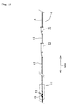
Fig. 1] Fig. 1 is s view illustrating the appearance configuration of an intravascular drug elution-type catheter 10 in a state where an elasticallydeformable portion 11 is in an inflated shape. - [
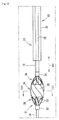
Fig. 2] Fig. 2 is an enlarged view of the intravascular drug elution-type catheter 10 in a region II ofFig. 1 . - [
Fig. 3] Fig. 3 is a cross sectional view of an elasticallydeformable portion 11 along the III-III line ofFig. 2 . - [
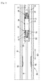
Fig. 4] Fig. 4 is a cross sectional view of the intravascular drug elution-type catheter 10 in a state where the elasticallydeformable portion 11 is in a deflated shape. - [
Fig. 5] Fig. 5 is a schematic view illustrating a state of inserting the intravascular drug elution-type catheter 10 into ablood vessel 90 by forming the elasticallydeformable portion 11 into a deflated shape. - [
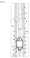
Fig. 6] Fig. 6 is a schematic view illustrating a state where a drug is infiltrated into astenosis portion 92 by forming the elasticallydeformable portion 11 into an inflated shape. - [
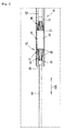
Fig. 7] Fig. 7 is an enlarged view illustrating a modification of the intravascular drug elution-type catheter 10. - Hereinafter, a preferable embodiment of the invention is described. This embodiment is merely one embodiment of the invention, and it is a matter of course that embodiment can be modified in the range where the scope of the invention is not altered.
- As illustrated in
Fig. 1 , the intravascular drug elution-type catheter 10 according to this embodiment has ashaft 12 provided with an elasticallydeformable portion 11 at the top end side and acatheter body 13 into which theshaft 12 is inserted. - The
catheter body 13 has atube 21 having a lumen 20 (first lumen) as the main structure. Thetube 21 is a molded body of a soft plastic which can elastically deform, such as polyamide and polyether amide. Thetube 21 has substantially the same outer diameter over alongitudinal direction 101. Thelumen 20 also has substantially the same inner diameter over thelongitudinal direction 101. The inner diameter of thelumen 20 is adjusted to a diameter which allows the elasticallydeformable portion 11 and theshaft 12 to pass. The length in thelongitudinal direction 101 of thetube 21 is adjusted as appropriate considering the length from a catheter insertion portion, such as the human limbs, to an affected portion. - At the proximal end of the
tube 21, ahandle portion 22 is provided. Thehandle portion 22 is a cylindrical member having an internal space continuous to thelumen 20. Thehandle portion 22 is a molded body of resin, such as polypropylene and ABS. Thehandle portion 22 can serve as a grip in operation of insertion and removal of thetube 21. Although not illustrated inFig. 1 , thehandle portion 22 may be provided with a blade as appropriate in order to facilitate rotation operation around theaxial direction 101. In this embodiment, the proximal end side refers to the rear side to the direction where the intravascular drug elution-type catheter 10 is inserted into the body. The top end side refers to the front side to the direction where the intravascular drug elution-type catheter 10 is inserted into the body. - The
shaft 12 is a thin and long tube made from stainless steel for medical treatment. Theshaft 12 may be coated with fluororesin or the like. The internal space of theshaft 12 allows aguide wire 14 to pass. Theshaft 12 can elastically deform along a curve shape of the arterial blood vessel and the like and has rigidity with which theshaft 12 does not buckle in thelongitudinal direction 101. - To the proximal end of the
shaft 12, ahandle portion 25 is connected. Thehandle portion 25 is a cylindrical member having an internal space continuous the internal space of theshaft 12. Thehandle portion 25 is a molded body of resin, such as polypropylene and ABS. Thehandle portion 25 can serve as a grip when inserting/removing theshaft 12 into/from thecatheter body 13 or inserting/removing theguide wire 14 into/from theshaft 12. - The elastically
deformable portion 11 is provided at the top end of theshaft 12. The elasticallydeformable portion 11 has a fixedring 31, aslide ring 32, and a plurality ofwire members 33. The fixedring 31 is a cylindrical member into which theguide wire 14 can be inserted. The fixedring 31 is fixed to the top end of theshaft 12, and the internal space is continuous to the internal space of theshaft 12. - The
slide ring 32 is disposed apart from the fixedring 31 at the top end side in thelongitudinal direction 101. Theslide ring 32 is a cylindrical member into which theguide wire 14 can be inserted. The internal space of theslide ring 32 is disposed in such a manner as to be on the same axis as that of the internal space of the fixedring 31. Therefore, theguide wire 14 which is inserted into the internal space of the fixedring 31 to be extended to the top end side in thelongitudinal direction 101 along thelongitudinal direction 101 can be inserted into the internal space of theslide ring 32. - The
wire members 33 are stretched between the fixedring 31 and theslide ring 32. Thewire members 33 connect the fixedring 31 and theslide ring 32. Thewire members 33 are disposed apart from each other in acircumferential direction 102 around theguide wire 14 extended along thelongitudinal direction 101. The spaced interval between thewire members 33 is adjusted to the size which allows the blood to smoothly circulate through the space between theadjacent wire members 33, and specifically, is about several millimeters. - Each
wire member 33 is spirally extended in thelongitudinal direction 101 between the fixedring 31 and theslide ring 32 and united by the fixedring 31 and theslide ring 32. Thus, the elasticallydeformable portion 11 defined by eachwire member 33 presents the outer diameter in a basket shape in which the outer diameter of thecentral portion 34 is the maximum diameter. Theguide wire 14 is inserted into the internal space in the basket shape, i.e., inside in thediameter direction 103 of eachwire member 33. - As a material of each
wire member 33, a shape memory alloy is preferable and, specifically, a Ni-Ti alloy, a Cu-Zn-Al alloy, a Cu-Al-Ni alloy, and the like are mentioned. By the shape memorized by eachwire member 33, the elasticallydeformable portion 11 is maintained in the inflated shape in the basket shape where thewire members 33 are spaced from each other and the outer diameter of thecentral portion 34 is enlarged as illustrated inFig. 2 . Then, when external force inside in the diameter direction, i.e., the central side into which theguide wire 14 is inserted, acts on eachwire member 33, eachwire member 33 comes close to each other, so that the elasticallydeformable portion 11 elastically deforms into a deflated shape where the outer diameter of thecentral portion 34 decreases as illustrated inFig. 4 . - As illustrated in
Figs. 2 and3 , thedrug holding film 15 is stretched only at thecentral portion 34 of the elasticallydeformable portion 11 in thecircumferential direction 102 relative to thewire members 33. In other words, thedrug holding film 15 is not stretched between thewire members 33 at thetop end portion 35 and theproximal end portion 36 of the elasticallydeformable portion 11. - As a material of the
drug holding film 15, materials having biocompatibility and capable of holding a desired drug and eluting the held drug in a blood vessel are preferable, and, specifically, polyurethane, polyethylene, polyester, polypropylene, polyamide, polytetrafluoroethylene, polyvinylidene fluoride, and the like are mentioned. Thedrug holding film 15 is stretched with moderate tension between thewire members 33 at thecentral portion 34 when the elasticallydeformable portion 11 is in the inflated shape. Thedrug holding film 15 has flexibility, and therefore when the elasticallydeformable portion 11 is in the deflated shape, thedrug holding film 15 bends between thewire members 33 to follow the shape change of the elasticallydeformable portion 11. - The
drug holding film 15 is stretched between thewire members 33 by the elasticallydeformable portion 11 being immersed in an solution serving as the material of thedrug holding film 15, and then dried. In this case, by only thetop end portion 35 and thecentral portion 34 of the elasticallydeformable portion 11 being immersed in a solution, thedrug holding film 15 is stretched between thewire members 33 in a state where thedrug holding film 15 is bonded to thewire members 33 at portions other than aproximal end portion 36, i.e., at the top end portion and thecentral portion 34. Thereafter, at thetop end portion 35 of the elasticallydeformable portion 11, thedrug holding film 15 stretched between thewire members 33 is cut by laser. As a result, as illustrated inFig. 3 , at thetop end portion 35 and theproximal end portion 36, thedrug holding film 15 is not present between thewire members 33, and then thedrug holding film 15 is stretched between thewire members 33 only at thecentral portion 34. - The
drug holding film 15 is coated with a drug. The drug is not particularly limited. Mentioned as a drug for preventing re-narrowing after expanding a stenosis portion of the coronary arteries, paclitaxel and analogues thereof, rapamycin and analogues thereof, β-lapachone and analogues thereof, biological vitamin D and analogues thereof, and the like. - A layer coated with the
drug holding film 15 may contain an additive and the like for the purpose of, for example, enhancing discharge of the drug in a blood vessel, besides the drugs mentioned above. On the layer of the drug, a protective layer for preventing loss of the drug while passing through a blood vessel may be further laminated. The drug may be held in thedrug holding film 15 not only by coating thedrug holding film 15 with the drug but also infiltrating the drug into thedrug holding film 15. - Hereinafter, a method for using the intravascular drug elution-
type catheter 10 is described. - The intravascular drug elution-
type catheter 10 is inserted into theblood vessel 90 having ablood vessel wall 91 to be medically treated. Theblood vessel wall 91 is thestenosis portion 92 expanded in the percutaneous transluminal coronary angioplasty (PTCA), for example, and is thestenosis portion 92 into which a drug is infiltrated in order to prevent re-narrowing. - Before the intravascular drug elution-
type catheter 10 is inserted into theblood vessel 90, theguide wire 14 is inserted into theblood vessel 90 to reach theblood vessel wall 91. Such insertion of theguide wire 14 is achieved by known techniques disclosed in Japanese Unexamined Patent Application Publication Nos.2006-326226 2006-230442 - When the intravascular drug elution-
type catheter 10 is inserted into theblood vessel 90, the elasticallydeformable portion 11 is formed into a deflated shape, and accommodated in thelumen 20 of thecatheter body 13 as illustrated inFig. 5 . Thedrug holding film 15 follows the deflation of the elasticallydeformable portion 11 to be deflated, and is also accommodated in thelumen 20. The proximal end of theguide wire 14 is inserted into theslide ring 32 of the elasticallydeformable portion 11 from the top end side of the intravascular drug elution-type catheter 10 in this state, i.e., the top end side of thecatheter body 13. Theguide wire 14 is further inserted into the fixedring 31 from the internal space of the elasticallydeformable portion 11, and inserted into the internal space of theshaft 12. Then, the intravascular drug elution-type catheter 10 is inserted into theblood vessel 90 along theguide wire 14. - When the top end side of the
catheter body 13 reaches near thestenosis portion 92 of theblood vessel wall 91 as illustrated inFig. 5 , thehandle portions shaft 12 is inserted into thecatheter body 13. More specifically, theshaft 12 is relatively pushed out to the top end side relative to thecatheter body 13. Thus, the elasticallydeformable portion 11 is pushed out from thelumen 20 of thecatheter body 13. As illustrated inFig. 6 , the pushed-out elasticallydeformable portion 11 elastically returns to an inflated shape from the deflated shape, and maintains the inflated shape. With the shape change of the elasticallydeformable portion 11, i.e., with the shape change of the elasticallydeformable portion 11 into a basket shape, thedrug holding film 15 is stretched in the circumferential direction relative to thewire members 33. Thedrug holding film 15 presses thestenosis portion 92 of theblood vessel wall 91. By holding pressing of thestenosis portion 92 by thedrug holding film 15 for a predetermined time, the drug is infiltrated into thestenosis portion 92 from thedrug holding film 15. - The
drug holding film 15 is stretched only at thecentral portion 34 of the elasticallydeformable portion 11 in the circumferential direction relative to thewire members 33 and thedrug holding film 15 is not present between thewire members 33 at thetop end portion 35 and theproximal end portion 36. Therefore, while the elasticallydeformable portion 11 in the inflated shape is left in theblood vessel 90, the blood flowing through theblood vessel 90 can circulate through the elasticallydeformable portion 11 from thetop end portion 35 to theproximal end portion 36 or from theproximal end portion 36 to thetop end portion 35. It is a matter of course that the blood can circulate also through the internal space of the basket-shaped elasticallydeformable portion 11. Therefore, while thedrug holding film 15 is pressed against thestenosis portion 92 by the elasticallydeformable portion 11 in the inflated shape, the blood flow is not blocked due to blocking of theblood vessel 90. - When a predetermined time for infiltrating the drug into the
stenosis portion 92 passes, thehandle portions shaft 12 is drawn out relative to thecatheter body 13. More specifically, theshaft 12 is relatively drawn back to the proximal end side relative to thecatheter body 13. Thus, the elasticallydeformable portion 11 in an inflated shape is drawn into thelumen 20 of thecatheter body 13. In the elasticallydeformable portion 11, thewire members 33 are extended in such a manner as to continuously spread to the outside in thediameter direction 103 from the fixedring 31 to theproximal end portion 36 and thecentral portion 34. Therefore, thewire members 33 are elastically deformed to the inside in thediameter direction 103 with the top end of thecatheter body 13 as a guide. Thus, the elasticallydeformable portion 11 is accommodated in thelumen 20 of thecatheter body 13 while the shape of the elasticallydeformable portion 11 gradually changes from the inflated shape to the deflated shape. Thedrug holding film 15 follows the shape change of the elasticallydeformable portion 11 to bend between thewire members 33 from the state where thedrug holding film 15 is stretched between thewire members 33 at thecentral portion 34. Then, when the elasticallydeformable portion 11 is completely accommodated in thelumen 20 of thecatheter body 13, the intravascular drug elution-type catheter 10 is drawn out from theblood vessel 90. - According to the intravascular drug elution-
type catheter 10 of this embodiment, when the intravascular drug elution-type catheter 10 is inserted into theblood vessel 90, the elasticallydeformable portion 11 is formed into a deflated shape and accommodated in thelumen 20 of thecatheter body 13. When the top end side of thecatheter body 13 reaches near thestenosis portion 92 of theblood vessel wall 91, theshaft 12 is inserted into thecatheter body 13, the elasticallydeformable portion 11 is pushed out from thelumen 20 of thecatheter body 13 to elastically return to an inflated shape from the deflated shape, and then thedrug holding film 15 presses thestenosis portion 92. Thus, the drug held in thedrug holding film 15 can be infiltrated into thestenosis portion 92. - Since the
drug holding film 15 is stretched only at thecentral portion 34 of the elasticallydeformable portion 11 in thecircumferential direction 102 relative to thewire members 33, the blood can circulate from thetop end portion 35 to theproximal end portion 36 and from theproximal end portion 36 to thetop end portion 35 in a state where the elasticallydeformable portion 11 maintains the inflated shape. Thus, the shape in which theelastic deformation part 11 is inflated can be maintained in theblood vessel 90 for a desired time without blocking the blood flow toward the peripheral side. - The
drug holding film 15 is stretched between thewire members 33 from thecentral portion 34 to thetop end portion 35 of the elasticallydeformable portion 11, and then thedrug holding film 15 between thewire members 33 is cut at thetop end portion 35. Therefore, even when thedrug holding film 15 slides to the inner wall of thecatheter body 13 in thelumen 20 when the elasticallydeformable portion 11 accommodated in thelumen 20 of thecatheter body 13 is pushed out to the outside, position shift of thedrug holding film 15 to thewire members 33 of the elasticallydeformable portion 11 is difficult to occur. Moreover, since the regions between thewire members 33 are cut at thetop end portion 35 of the elasticallydeformable portion 11, the circulation of the blood is not hindered by thedrug holding film 15 at thetop end portion 35. - Hereinafter, a modification of the above-described embodiment is described. In the above-described embodiment, the
catheter body 13 is an over-the-wire-type. In contrast thereto, in this modification, thecatheter body 13 is a rapid-exchange type and is different from the above-described embodiment in that theguide wire 14 is not inserted into theshaft 41 and theguide wire 14 is inserted into acatheter body 42 of a so-called double lumen type. The elasticallydeformable portion 11 has the same structure as that of the above-described embodiment, and the same reference numerals as those of the above-described embodiment are given. - As illustrated in
Fig. 7 , thecatheter body 42 has twolumens tube 45. The lumen 44 (second lumen) is formed by the internal space of atube 46. The twotubes lumens lumen 43, theshaft 41 is inserted. Into thelumen 44, theguide wire 14 is inserted. - The length in the
longitudinal direction 101 of thetubes blood vessel 90. Therefore, in thetube 46, only a portion ofguide wire 14 is inserted into thelumen 44. - To the proximal end of the
tube 45, acatheter shaft 47 is connected and is extended in thelongitudinal direction 101. Thecatheter shaft 47 is a stainless steel wire member for medical treatment and has elasticity with which thecatheter shaft 47 elastically bends along a curve shape of theblood vessel 90 and rigidity with which thecatheter shaft 47 does not buckle in thelongitudinal direction 101. Although not illustrated inFig. 7 , the same handle portion as thehandle portion 22 is provided at the proximal end side of thecatheter shaft 47. - The
shaft 41 is a stainless steel wire member for medical treatment. Theshaft 41 can elastically deform along a curve shape of theblood vessel 90 and has rigidity with which theshaft 41 does not buckle in thelongitudinal direction 101. The elasticallydeformable portion 11 is provided at the top end side of theshaft 41. The top end side of theshaft 41 is inserted into the fixedring 31 and theslide ring 32 of the elasticallydeformable portion 11. The fixedring 31 is fixed to theshaft 41. Theslide ring 32 is slidable to theshaft 41. - In the
lumen 43 of thetube 45, the elasticallydeformable portion 11 in a deflated shape can be accommodated. Then, when theshaft 41 is relatively pushed out to the top end side relative to thecatheter body 42, the elasticallydeformable portion 11 is pushed out from thelumen 43 of thecatheter body 42. Then, as illustrated inFig. 7 , the pushed-out elasticallydeformable portion 11 elastically returns to an inflated shape from the deflated shape, and maintains the inflated shape. When theshaft 41 is relatively drawn back to the proximal end side relative to thecatheter body 42, the elasticallydeformable portion 11 in the inflated shape is drawn into thelumen 43 of thecatheter body 42 while changing the shape into a deflated shape. By such a modification, the same effects as those in the above-described embodiment are demonstrated. -
10 Intravascular drug elution- type catheter 11 Elastically deformable portion 12, 41 Shaft 13, 42 Catheter body 14 Guide wire 15 Drug holding film 20, 43 Lumen (first lumen) 33 Wire member 34 Central portion 35 Top end portion 44 Lumen (second lumen)
Claims (5)
- An intravascular drug elution-type catheter, comprising:an elastically deformable portion provided with a plurality of wire members that are disposed apart from each other in the circumferential direction, maintaining an inflated shape in a basket shape in which the wire members are apart from each other and the outer diameter of the central portion in the longitudinal direction is enlarged, and elastically deforming into a deflated shape in which the wire members come close to each other, so that the outer diameter of the central portion is reduced;a shaft provided with the elastically deformable portion at the top end side thereof;a catheter body having a first lumen through which the elastically deformable portion in the deflated shape and the shaft can pass;a drug holding film which is stretched only at the central portion of the elastically deformable portion in the circumferential direction relative to the wire members in the inflated shape, which has flexibility with which the drug holding film follows the change in the shape of the elastically deformable portion, and which can hold and elute a drug; andthe drug held in the drug holding film.
- The intravascular drug elution-type catheter according to Claim 1, wherein the drug holding film is bonded to the wire members at least from the central portion of the elastically deformable portion to the top end portion thereof and regions between the wire members are cut at the top end portion.
- The intravascular drug elution-type catheter according to Claim 1 or 2, wherein the elastically deformable portion is one in which the wire members are spirally extended in the longitudinal direction, both ends of the wire members are united, and the diameter of the central portion is the maximum diameter.
- The intravascular drug elution-type catheter according to any one of Claims 1 to 3, wherein
the shaft is a tubular body through which the guide wire can pass, and
the elastically deformable portion is one through which the guide wire can pass inside in the diameter direction relative to the wire members. - The intravascular drug elution-type catheter according to any one of Claims 1 to 3, wherein
the catheter body has a second lumen through which the guide wire can pass, and
the elastically deformable portion is one through which the shaft can pass inside in the diameter direction relative to the wire members.
Applications Claiming Priority (2)
| Application Number | Priority Date | Filing Date | Title |
|---|---|---|---|
| JP2010165553A JP5799488B2 (en) | 2010-07-23 | 2010-07-23 | Intravascular drug elution catheter |
| PCT/JP2011/066511 WO2012011515A1 (en) | 2010-07-23 | 2011-07-21 | Intravascular drug elution-type catheter |
Publications (2)
| Publication Number | Publication Date |
|---|---|
| EP2596829A1 true EP2596829A1 (en) | 2013-05-29 |
| EP2596829A4 EP2596829A4 (en) | 2017-11-01 |
Family
ID=45496933
Family Applications (1)
| Application Number | Title | Priority Date | Filing Date |
|---|---|---|---|
| EP11809685.8A Withdrawn EP2596829A4 (en) | 2010-07-23 | 2011-07-21 | Intravascular drug elution-type catheter |
Country Status (4)
| Country | Link |
|---|---|
| US (1) | US20130116634A1 (en) |
| EP (1) | EP2596829A4 (en) |
| JP (1) | JP5799488B2 (en) |
| WO (1) | WO2012011515A1 (en) |
Families Citing this family (1)
| Publication number | Priority date | Publication date | Assignee | Title |
|---|---|---|---|---|
| US9795299B2 (en) * | 2013-09-27 | 2017-10-24 | Covidien Lp | Modular physiological sensing patch |
Family Cites Families (11)
| Publication number | Priority date | Publication date | Assignee | Title |
|---|---|---|---|---|
| FR2624747A1 (en) * | 1987-12-18 | 1989-06-23 | Delsanti Gerard | REMOVABLE ENDO-ARTERIAL DEVICES FOR REPAIRING ARTERIAL WALL DECOLLEMENTS |
| US5071407A (en) * | 1990-04-12 | 1991-12-10 | Schneider (U.S.A.) Inc. | Radially expandable fixation member |
| US6641611B2 (en) | 2001-11-26 | 2003-11-04 | Swaminathan Jayaraman | Therapeutic coating for an intravascular implant |
| JP4656494B2 (en) | 2005-02-22 | 2011-03-23 | ニプロ株式会社 | Guiding catheter |
| JP2006326226A (en) | 2005-05-30 | 2006-12-07 | Nipro Corp | Guiding catheter |
| US20080058856A1 (en) * | 2005-06-28 | 2008-03-06 | Venkatesh Ramaiah | Non-occluding dilation device |
| EP2241342A3 (en) | 2006-11-20 | 2011-01-12 | Lutonix, Inc. | Drug releasing coatings for medical devices |
| JP5172180B2 (en) * | 2007-03-19 | 2013-03-27 | トーヨーエイテック株式会社 | DLC film modification method, medical material, and medical device manufacturing method |
| US8100855B2 (en) * | 2007-09-17 | 2012-01-24 | Abbott Cardiovascular Systems, Inc. | Methods and devices for eluting agents to a vessel |
| US8066757B2 (en) * | 2007-10-17 | 2011-11-29 | Mindframe, Inc. | Blood flow restoration and thrombus management methods |
| EP2224991B1 (en) * | 2007-11-30 | 2018-02-21 | Cook Medical Technologies LLC | Method and device for vascular therapy |
-
2010
- 2010-07-23 JP JP2010165553A patent/JP5799488B2/en active Active
-
2011
- 2011-07-21 EP EP11809685.8A patent/EP2596829A4/en not_active Withdrawn
- 2011-07-21 US US13/805,824 patent/US20130116634A1/en not_active Abandoned
- 2011-07-21 WO PCT/JP2011/066511 patent/WO2012011515A1/en not_active Ceased
Non-Patent Citations (1)
| Title |
|---|
| See references of WO2012011515A1 * |
Also Published As
| Publication number | Publication date |
|---|---|
| JP2012024316A (en) | 2012-02-09 |
| EP2596829A4 (en) | 2017-11-01 |
| US20130116634A1 (en) | 2013-05-09 |
| WO2012011515A1 (en) | 2012-01-26 |
| JP5799488B2 (en) | 2015-10-28 |
Similar Documents
| Publication | Publication Date | Title |
|---|---|---|
| EP2596828A1 (en) | Intravascular hemostasis-type catheter | |
| EP1366732B1 (en) | Stent delivery system having a fixed guide wire | |
| US6692482B2 (en) | Adjustable length conversion adapter for dilatation catheters | |
| US5807355A (en) | Catheter with rapid exchange and OTW operative modes | |
| US9849013B2 (en) | Stent delivery catheter | |
| US8676301B2 (en) | Guide wire incorporating a handle | |
| US20080269641A1 (en) | Method of using a guidewire with stiffened distal section | |
| AU2014364599B2 (en) | Balloon catheters and system and methods for delivering stents using such catheters | |
| US20170028170A1 (en) | Guide catheter extension device and methods of use for cardiology procedures | |
| AU2004206890A1 (en) | Adjustable length catheter | |
| EP2282699A1 (en) | Sleeves for positioning a stent on a delivery balloon cathether system | |
| CN111491687A (en) | Drug delivery balloon catheter | |
| JP5015772B2 (en) | Balloon catheter | |
| US8021409B2 (en) | Deployment catheter | |
| US20050070847A1 (en) | Rapid-exchange balloon catheter with hypotube shaft | |
| US20050107819A1 (en) | Catheter with a sectional guidewire shaft | |
| US20130116634A1 (en) | Intravascular drug elution-type catheter | |
| US20060253185A1 (en) | Catheter for stent delivery having expanded inner member | |
| WO2023189377A1 (en) | Catheter | |
| JP2015181674A (en) | balloon catheter |
Legal Events
| Date | Code | Title | Description |
|---|---|---|---|
| PUAI | Public reference made under article 153(3) epc to a published international application that has entered the european phase |
Free format text: ORIGINAL CODE: 0009012 |
|
| 17P | Request for examination filed |
Effective date: 20130222 |
|
| AK | Designated contracting states |
Kind code of ref document: A1 Designated state(s): AL AT BE BG CH CY CZ DE DK EE ES FI FR GB GR HR HU IE IS IT LI LT LU LV MC MK MT NL NO PL PT RO RS SE SI SK SM TR |
|
| DAX | Request for extension of the european patent (deleted) | ||
| RA4 | Supplementary search report drawn up and despatched (corrected) |
Effective date: 20171005 |
|
| RIC1 | Information provided on ipc code assigned before grant |
Ipc: A61M 29/02 20060101AFI20170928BHEP Ipc: A61M 25/06 20060101ALN20170928BHEP Ipc: A61M 25/00 20060101ALI20170928BHEP |
|
| STAA | Information on the status of an ep patent application or granted ep patent |
Free format text: STATUS: THE APPLICATION HAS BEEN WITHDRAWN |
|
| 18W | Application withdrawn |
Effective date: 20180214 |