EP2596825A1 - Needle assembly attachment and removal device - Google Patents
Needle assembly attachment and removal device Download PDFInfo
- Publication number
- EP2596825A1 EP2596825A1 EP11190581.6A EP11190581A EP2596825A1 EP 2596825 A1 EP2596825 A1 EP 2596825A1 EP 11190581 A EP11190581 A EP 11190581A EP 2596825 A1 EP2596825 A1 EP 2596825A1
- Authority
- EP
- European Patent Office
- Prior art keywords
- carriage
- needle assembly
- removal device
- assembly attachment
- carrier
- Prior art date
- Legal status (The legal status is an assumption and is not a legal conclusion. Google has not performed a legal analysis and makes no representation as to the accuracy of the status listed.)
- Ceased
Links
Images



Classifications
-
- A—HUMAN NECESSITIES
- A61—MEDICAL OR VETERINARY SCIENCE; HYGIENE
- A61M—DEVICES FOR INTRODUCING MEDIA INTO, OR ONTO, THE BODY; DEVICES FOR TRANSDUCING BODY MEDIA OR FOR TAKING MEDIA FROM THE BODY; DEVICES FOR PRODUCING OR ENDING SLEEP OR STUPOR
- A61M5/00—Devices for bringing media into the body in a subcutaneous, intra-vascular or intramuscular way; Accessories therefor, e.g. filling or cleaning devices, arm rests
- A61M5/178—Syringes
- A61M5/31—Details
- A61M5/32—Needles; Details of needles pertaining to their connection with syringe or hub; Accessories for bringing the needle into, or holding the needle on, the body; Devices for protection of needles
- A61M5/34—Constructions for connecting the needle, e.g. to syringe nozzle or needle hub
- A61M5/344—Constructions for connecting the needle, e.g. to syringe nozzle or needle hub using additional parts, e.g. clamping rings or collets
-
- A—HUMAN NECESSITIES
- A61—MEDICAL OR VETERINARY SCIENCE; HYGIENE
- A61M—DEVICES FOR INTRODUCING MEDIA INTO, OR ONTO, THE BODY; DEVICES FOR TRANSDUCING BODY MEDIA OR FOR TAKING MEDIA FROM THE BODY; DEVICES FOR PRODUCING OR ENDING SLEEP OR STUPOR
- A61M5/00—Devices for bringing media into the body in a subcutaneous, intra-vascular or intramuscular way; Accessories therefor, e.g. filling or cleaning devices, arm rests
- A61M5/178—Syringes
- A61M5/31—Details
- A61M5/32—Needles; Details of needles pertaining to their connection with syringe or hub; Accessories for bringing the needle into, or holding the needle on, the body; Devices for protection of needles
- A61M5/3205—Apparatus for removing or disposing of used needles or syringes, e.g. containers; Means for protection against accidental injuries from used needles
- A61M5/3276—Means imparting rotational movement to the needle or needle hub in order to assist in its disconnection from syringe nozzle
-
- A—HUMAN NECESSITIES
- A61—MEDICAL OR VETERINARY SCIENCE; HYGIENE
- A61M—DEVICES FOR INTRODUCING MEDIA INTO, OR ONTO, THE BODY; DEVICES FOR TRANSDUCING BODY MEDIA OR FOR TAKING MEDIA FROM THE BODY; DEVICES FOR PRODUCING OR ENDING SLEEP OR STUPOR
- A61M5/00—Devices for bringing media into the body in a subcutaneous, intra-vascular or intramuscular way; Accessories therefor, e.g. filling or cleaning devices, arm rests
- A61M5/178—Syringes
- A61M5/31—Details
- A61M5/32—Needles; Details of needles pertaining to their connection with syringe or hub; Accessories for bringing the needle into, or holding the needle on, the body; Devices for protection of needles
- A61M5/34—Constructions for connecting the needle, e.g. to syringe nozzle or needle hub
- A61M5/347—Constructions for connecting the needle, e.g. to syringe nozzle or needle hub rotatable, e.g. bayonet or screw
-
- A—HUMAN NECESSITIES
- A61—MEDICAL OR VETERINARY SCIENCE; HYGIENE
- A61M—DEVICES FOR INTRODUCING MEDIA INTO, OR ONTO, THE BODY; DEVICES FOR TRANSDUCING BODY MEDIA OR FOR TAKING MEDIA FROM THE BODY; DEVICES FOR PRODUCING OR ENDING SLEEP OR STUPOR
- A61M5/00—Devices for bringing media into the body in a subcutaneous, intra-vascular or intramuscular way; Accessories therefor, e.g. filling or cleaning devices, arm rests
- A61M5/178—Syringes
- A61M5/31—Details
- A61M5/32—Needles; Details of needles pertaining to their connection with syringe or hub; Accessories for bringing the needle into, or holding the needle on, the body; Devices for protection of needles
- A61M5/3205—Apparatus for removing or disposing of used needles or syringes, e.g. containers; Means for protection against accidental injuries from used needles
- A61M2005/3208—Apparatus for removing or disposing of used needles or syringes, e.g. containers; Means for protection against accidental injuries from used needles by application of rotational movement to the needle hub, e.g. by use of electrically driven toothed wheels
Definitions
- the invention relates to a needle assembly attachment and removal device for attaching a needle assembly to and removing a needle assembly from a medicament delivery device.
- Administering a medicament by injection is a process which presents a number of risks and challenges for patients and healthcare professionals, both mental and physical. Improper handling of medicament delivery devices may result in needle stick injuries. In any situation in which a patient or healthcare professional is required to manually attach/remove the needle assembly, there is a risk of needle stick injury.
- manually attaching the needle assembly may lead to mismatch of screw threads, resulting in an obliquely-oriented needle. This may lead to a defective septum or to an inaccurate injection.
- a needle assembly attachment and removal device comprises a case having a base and a longitudinal axis, a carriage axially movable with the case from a first position to a second position, a carrier rotatably coupled to the carriage and adapted to hold a needle assembly, and a gearing arrangement rotatably coupled to the carriage and adapted to rotate the carrier in a first rotational direction as the carriage moves from the first position to the second position and in a second rotational direction as the carriage moves from the second position to the first position.
- the needle assembly attachment and removal device further comprises a retainer coupled to the case or the carriage or the carrier and adapted to align a medicament delivery device with the needle assembly.
- the base has a larger cross-section than the case.
- the needle assembly attachment and removal device further comprises a cap clamp coupled to the carrier and adapted to engage an outer cap of the needle assembly.
- the cap clamp includes resilient clamp arms adapted to engage a portion of the outer cap.
- the needle assembly attachment and removal device further comprises a push rod slidably coupled to the carriage, and a clamp ring coupled to the push rod and adapted to apply a compressive force on the clamp arms to maintain engagement with the portion of the outer cap. The push rod urges the clamp ring against the clamp arms when the push rod engages the base.
- the gearing arrangement includes a rack disposed in the case, and a pinion having a first gear face adapted to engage a gear wheel coupled to the carrier and a second gear face adapted to engage the rack.
- the rack is disposed at an angle relative to the longitudinal axis of the case, and the second gear face has a variable diameter.
- the gearing arrangement further includes a torsion spring applying a rotational biasing force to the pinion, and movement of the carriage from the first position to the second position causes the pinion to rotate and energize the torsion spring.
- the carriage rotates about the longitudinal axis and a rotational axis of the pinion is orthogonal to the longitudinal axis.
- the needle assembly attachment and removal device further comprises a compression spring adapted to engage a spring stop formed on the base. The compression spring is energized when the carriage is in the second position.
- the carriage includes a resilient pin adapted to engage a retaining groove in the case.
- the pin As the carriage moves from the first position to the second position, the pin enters a first portion of the retaining groove and deflects toward a longitudinal axis of the case.
- the carriage When the pin engages a second portion of the retaining groove, the carriage is locked in the second position.
- an axial force on the carriage directed toward the base causes the pin to disengage the second portion and enter a third portion of the retaining groove which allows the carriage to return to the first position.
- a force in the compression spring propels the carriage toward the first position when the pin enters the third portion of the retaining groove.
- the needle assembly attachment and removal device further comprises a clutch disposed between the cap clamp and the carrier.
- the clutch prevents rotation of the cap clamp relative to the carrier in the first rotational direction until a predetermined torque is applied on the outer cap.
- the clutch prevents rotation of the cap clamp relative to the carrier in the second rotational direction.
- the carriage includes guide wheels adapted to engage channels formed in the base.
- the needle assembly attachment and removal device may be used with delivery devices such as injection pens (e.g. for re-usable or disposable Insulin or Heparin pens) and with all kinds of needle assemblies, such as pen needles.
- delivery devices such as injection pens (e.g. for re-usable or disposable Insulin or Heparin pens) and with all kinds of needle assemblies, such as pen needles.
- the needle assembly attachment and removal device allows for an easy and safe mounting and demounting of needle assemblies onto a delivery device while preventing a user from needle stick injuries.
- the needle assembly attachment and removal device allows the application of the proper torque to engage the needle assembly and the delivery device. This may avoid an unwanted disassembling of a cartridge holder from a body of the delivery device which may occur, if the torque for releasing the needle assembly is greater than the release torque of the cartridge holder.
- the needle assembly attachment and removal device allow for single handed operation.
- the needle assembly attachment and removal device may be adapted for screw-type mounting and demounting accessories in different applications which require frequent attachment and removal.
- Figure 1A is a longitudinal section of a needle assembly attachment and removal device 1 in a first sectional plane according to an exemplary embodiment of the present invention.
- the device 1 is adapted to receive a medicament delivery device and to attach and remove a needle assembly 6 to and from the delivery device.
- the delivery device may be any medicament delivery device including, but not limited to, a pen injector, an auto-injector, a safety syringe, etc.
- the delivery device may include a cartridge holder adapted to hold a medicament-containing cartridge (not illustrated).
- the delivery device may be a single-use device (e.g., the delivery device is disposed of after the cartridge is empty) or a re-usable device (e.g., the cartridge may be replaced when empty or otherwise necessary).
- the needle assembly includes a needle hub 6.2 adapted to engage the delivery device and a needle 6.3 which has a distal tip 6.4 and a proximal tip 6.5 coupled to the needle hub 6.2.
- the proximal tip 6.5 is arranged to pierce a septum of a cartridge in the delivery device when the needle assembly 6 is mounted to the delivery device, and the distal tip 6.4 is used to pierce an injection site.
- the medicament can be displaced through a fluid channel within the needle 6.3.
- the needle hub 6.2 includes internal threads 6.6 for mating with threads formed on the delivery device.
- An inner needle cap 6.7 may be arranged over the needle 6.3.
- An outer cap 6.1 may be arranged over the needle hub 6.2, needle 6.3 and inner needle cap 6.7.
- the outer cap 6.1 may include features (e.g., grooves) which mate with corresponding features (e.g., ridges) on the needle hub 6.2, such that the outer cap 6.1 does not rotate relative to the needle hub 6.2 when they are engaged.
- the needle assembly attachment and removal device 1 comprises an elongate case 4 with a base 4.1 at a lower end.
- the base 4.1 may be planar to serve as a platform so that the device 1 may be placed on a surface during use.
- the base 4.1 may be have a larger cross-section than the case 4 to increase surface area and stability when placed on a surface.
- an underside of the base 4.1 may include a coating or matting adapted to frictionally engage a surface.
- An upper end of the case 4 has an opening adapted to receive the needle assembly 6 and the delivery device.
- the device 1 includes a retainer 2 arranged on a carriage 11 which is slidably arranged within the case 4 along a longitudinal axis L.
- the retainer 2 may comprise a plurality of axial arms which have contoured internal surfaces adapted to support align the delivery device when it is inserted into the device 1.
- the retainer 2 may ensure that the delivery device properly engages/disengages the needle assembly 6 (e.g., that the threads are aligned correctly).
- the device 1 includes a carrier 13 rotatably coupled to the carriage 11.
- a cap clamp 14 may be rotatably coupled to the carrier 13 via a clutch 15 (which is keyed to the carriage 11).
- the cap clamp 14 is adapted to engage the outer cap 6.1 of the needle assembly 6.
- Resilient clamp arms 3 may be disposed at a lower end of the cap clamp 14.
- a clamp ring 12 is disposed in the carriage 11 and coupled to a push rod 5, which is slidably coupled to the carriage 11.
- the clamp ring 12 is adapted to engage the clamp arms 3 to push the clamp arms 3 into frictional engagement with the outer cap 6.1.
- the clamp arms 3 may include a tapered surface 3.1 adapted to engage a corresponding tapered surface of the clamp ring 12.
- the clamp arms 3 may deflect and frictionally engage the outer cap 6.1, as described further below.
- the clutch 15 includes a ratchet face adapted to engage a corresponding ratchet face on the cap clamp 14. As explained further below, the clutch 15 limits an attachment torque applied to the needle assembly 6 when the needle assembly 6 is mounted on the delivery device.
- a pinion 8 is rotatably coupled to the carriage 11 and may include a torsion spring 9 applying a biasing force to the pinion 8.
- the pinion includes a first gear face 8.1 which is adapted to mate with a gear wheel 11.2 on the carrier 13 and a second gear face 8.2 which is adapted to mate with a rack 7 formed in the case 4.
- rotation of the pinion 8 causes rotation of the carrier 13.
- the rack 7 and the second gear face 8.2 form a rack and pinion arrangement having a variable transmission.
- the rack 7 may be arranged at an angle with respect to the longitudinal axis L so that a distance between the rack 7 and the longitudinal axis L increases along at least a portion of the length of the case 4 and is greatest near the base 4.1.
- the second gear face 8.2 has a variable diameter.
- the carriage 11 includes a compression spring 10 adapted to engage a spring stop 4.2 disposed on the base 4.1.
- the compression spring 10 compresses as the carriage 11 moves toward the base 4.1.
- the carriage 11 includes a pin 11.3 adapted to engage a retaining groove 4.3 formed adjacent the base 4.1.
- the retaining groove 4.3 may include various positions for the pin 11.3 to maintain the carriage 11 in a position relative to the case 4.
- the carriage 11 may include one or more guide wheels 11.1 adapted to engage one or more corresponding channels in the case 4 for facilitating the axial movement of the carriage 11 relative to the case 4 and for maintaining an angular position of the carriage 11 relative to the case 4.
- Figures 1A , 1 B and 2 show the device 1 in a pre-use state, in which the carriage 11 is in a first axial position relative to the case 4.
- the needle assembly 6 may be placed in the device 1 such that the outer cap 6.1 of the needle assembly 6 engages the cap clamp 14.
- the cap arms 3 may frictionally engage the outer cap 6.1 and/or the clamp ring 12 may prevent the cap arms 3 from deflecting and ensure a frictional hold on the outer cap 6.1.
- the delivery device is aligned with the needle aperture 2.1 of the retainer 2, and the retainer 2 aligns the delivery device with the needle hub 6.2 in the needle assembly.
- the carriage 11 translates towards the base 4.1.
- the second gear face 8.2 engages the rack 7 and because the first gear face 8.1 engages the gear wheel 11.2
- the carrier 13 rotates in a first rotational direction as the carriage 11 translates axially.
- the cap clamp 14 and outer cap 6.1 and needle hub 6.2
- rotate in the first rotational direction so that the threads 6.6 on the needle hub 6.2 engage the threads on the delivery device.
- the torque applied to the needle hub 6.2 increases as the carriage 11 translates towards the base 4.1.
- the torsion spring 9 is energized.
- the retaining groove 4.3 may have a first portion which is adapted to receive the pin 11.3 and deflect the pin 11.3 toward the longitudinal axis L.
- the compression spring 10 engages and compresses against the spring stop 4.2.
- the push rod 5 abuts the base 4.1 and further translation of the carriage 11 causes the clamp ring 12 to engage the clamp arms 3 to secure the outer cap 6.1 in the cap clamp 14.
- any further rotation of the carrier 13 relative to the needle hub 6.2 may cause the clutch 15 to disengage the cap clamp 14.
- the clutch 15 prevents over-tightening the needle hub 6.2.
- an audible feedback e.g., clicking of the slipping ratchet faces
- the device 1 may be used to remove the used needle hub 6.2.
- the delivery device may be reinserted into the device 1 by aligning with the retainer 2.
- a first tactile feedback (e.g., increased resistance) may be provided when the needle hub 6.2 engages the outer cap 6.1.
- the carriage 11 may be advanced toward the base 4.1 a small distance, and the pin 11.3 may disengage the second portion in the retaining groove 4.3 and resiliently deflect into a third portion, which may be a channel that does not obstruct axial movement of the pin 11.3 and allows the carriage 11 to translate axially away from the base 4.1.
- the force in the torsion spring 9 rotates the pinion 8 to climb up the rack 7, and the force in the compression spring 10 pushes the carriage 11 away from the base 4.1.
- the rotation of the pinion 8 results in rotation of the carrier 13 in a second rotational direction which disengages the needle hub 6.2 from the delivery device.
- the compression spring 10 is primarily active in a first part of a demounting cycle, e.g., to generate high torque and high rotational speed on the carrier 13 and the cap clamp 14 to loosen the thread 6.6 of the needle hub 6.2 from the threads on the delivery device.
- the push rod 5 no longer abuts the base 4.1 and the compression spring 10 disengages the spring stop 4.2.
- the remaining rotational force on the carriage 11 is supplied by the torsion spring 9.
- the torque of the torsion spring 9 suffices to return the delivery device to the initial upper end position and unscrew the needle hub 6.2 from the delivery device.
- the needle assembly 6 may be grasped and removed from the device 1 for disposal.
- the device 1 may include a locking mechanism (not shown) for locking the carriage 11 relative to the case 4.
- the locking mechanism may be a lever which locks the carriage 11 in a position (e.g., the second position) relative to the case 4 or a cover disposed over the needle aperture 2.1.
Landscapes
- Health & Medical Sciences (AREA)
- Engineering & Computer Science (AREA)
- Animal Behavior & Ethology (AREA)
- General Health & Medical Sciences (AREA)
- Biomedical Technology (AREA)
- Heart & Thoracic Surgery (AREA)
- Hematology (AREA)
- Life Sciences & Earth Sciences (AREA)
- Vascular Medicine (AREA)
- Anesthesiology (AREA)
- Public Health (AREA)
- Veterinary Medicine (AREA)
- Environmental & Geological Engineering (AREA)
- Infusion, Injection, And Reservoir Apparatuses (AREA)
- Hand Tools For Fitting Together And Separating, Or Other Hand Tools (AREA)
- Spinning Or Twisting Of Yarns (AREA)
- Knitting Machines (AREA)
Abstract
Described is a needle assembly attachment and removal device (1) comprising a case (4) having a base (4.1) and a longitudinal axis (L), a carriage (11) axially movable with the case (4) from a first position to a second position, a carrier (13) rotatably coupled to the carriage (11) and adapted to hold a needle assembly (6), and a gearing arrangement (7, 8) rotatably coupled to the carriage (11) and adapted to rotate the carrier (13) in a first rotational direction as the carriage (11) moves from the first position to the second position and in a second rotational direction as the carriage (11) moves from the second position to the first position.
Description
- The invention relates to a needle assembly attachment and removal device for attaching a needle assembly to and removing a needle assembly from a medicament delivery device.
- Administering a medicament by injection is a process which presents a number of risks and challenges for patients and healthcare professionals, both mental and physical. Improper handling of medicament delivery devices may result in needle stick injuries. In any situation in which a patient or healthcare professional is required to manually attach/remove the needle assembly, there is a risk of needle stick injury.
- In addition, manually attaching the needle assembly to the medicament delivery device can lead to over-tightening, which can result in injury when removing the needle assembly and/or structural damage to the medicament delivery device. Attempts to remove an over-tightened needle assembly can adversely affect other components of the medicament delivery device (e.g., in a reusable device, a cartridge holder may be loosened).
- Further, manually attaching the needle assembly may lead to mismatch of screw threads, resulting in an obliquely-oriented needle. This may lead to a defective septum or to an inaccurate injection.
- Thus, there is a need for a device for safely attaching and removing a needle assembly to/from a medicament delivery device.
- It is an object of the present invention to provide a needle assembly attachment and removal device for attaching a needle assembly to and removing the needle assembly from a medicament delivery device.
- In an exemplary embodiment, a needle assembly attachment and removal device according to the present invention comprises a case having a base and a longitudinal axis, a carriage axially movable with the case from a first position to a second position, a carrier rotatably coupled to the carriage and adapted to hold a needle assembly, and a gearing arrangement rotatably coupled to the carriage and adapted to rotate the carrier in a first rotational direction as the carriage moves from the first position to the second position and in a second rotational direction as the carriage moves from the second position to the first position.
- In an exemplary embodiment, the needle assembly attachment and removal device further comprises a retainer coupled to the case or the carriage or the carrier and adapted to align a medicament delivery device with the needle assembly.
- In an exemplary embodiment, the base has a larger cross-section than the case.
- In an exemplary embodiment, the needle assembly attachment and removal device further comprises a cap clamp coupled to the carrier and adapted to engage an outer cap of the needle assembly. The cap clamp includes resilient clamp arms adapted to engage a portion of the outer cap. The needle assembly attachment and removal device further comprises a push rod slidably coupled to the carriage, and a clamp ring coupled to the push rod and adapted to apply a compressive force on the clamp arms to maintain engagement with the portion of the outer cap. The push rod urges the clamp ring against the clamp arms when the push rod engages the base.
- In an exemplary embodiment, the gearing arrangement includes a rack disposed in the case, and a pinion having a first gear face adapted to engage a gear wheel coupled to the carrier and a second gear face adapted to engage the rack. The rack is disposed at an angle relative to the longitudinal axis of the case, and the second gear face has a variable diameter. The gearing arrangement further includes a torsion spring applying a rotational biasing force to the pinion, and movement of the carriage from the first position to the second position causes the pinion to rotate and energize the torsion spring. The carriage rotates about the longitudinal axis and a rotational axis of the pinion is orthogonal to the longitudinal axis.
- In an exemplary embodiment, the needle assembly attachment and removal device further comprises a compression spring adapted to engage a spring stop formed on the base. The compression spring is energized when the carriage is in the second position.
- In an exemplary embodiment, the carriage includes a resilient pin adapted to engage a retaining groove in the case. As the carriage moves from the first position to the second position, the pin enters a first portion of the retaining groove and deflects toward a longitudinal axis of the case. When the pin engages a second portion of the retaining groove, the carriage is locked in the second position. When the pin is engaged in the second portion of the retaining groove, an axial force on the carriage directed toward the base causes the pin to disengage the second portion and enter a third portion of the retaining groove which allows the carriage to return to the first position. A force in the compression spring propels the carriage toward the first position when the pin enters the third portion of the retaining groove.
- In an exemplary embodiment, the needle assembly attachment and removal device further comprises a clutch disposed between the cap clamp and the carrier. The clutch prevents rotation of the cap clamp relative to the carrier in the first rotational direction until a predetermined torque is applied on the outer cap. The clutch prevents rotation of the cap clamp relative to the carrier in the second rotational direction.
- In an exemplary embodiment, the carriage includes guide wheels adapted to engage channels formed in the base.
- In an exemplary embodiment the needle assembly attachment and removal device may be used with delivery devices such as injection pens (e.g. for re-usable or disposable Insulin or Heparin pens) and with all kinds of needle assemblies, such as pen needles. The needle assembly attachment and removal device allows for an easy and safe mounting and demounting of needle assemblies onto a delivery device while preventing a user from needle stick injuries.
- The needle assembly attachment and removal device allows the application of the proper torque to engage the needle assembly and the delivery device. This may avoid an unwanted disassembling of a cartridge holder from a body of the delivery device which may occur, if the torque for releasing the needle assembly is greater than the release torque of the cartridge holder.
- The risk of human error when mounting the needle assembly is minimized. This results in a reduced risk for loose needles, destroyed threads caused by excessive torque or crossed threads. The risk of an obliquely-oriented needle is also eliminated.
- The needle assembly attachment and removal device allow for single handed operation.
- The needle assembly attachment and removal device may be adapted for screw-type mounting and demounting accessories in different applications which require frequent attachment and removal.
- Further scope of applicability of the present invention will become apparent from the detailed description given hereinafter. However, it should be understood that the detailed description and specific examples, while indicating preferred embodiments of the invention, are given by way of illustration only, since various changes and modifications within the spirit and scope of the invention will become apparent to those skilled in the art from this detailed description.
- The present invention will become more fully understood from the detailed description given hereinbelow and the accompanying drawings which are given by way of illustration only, and thus, are not limitive of the present invention, and wherein:
- Figure 1A
- is a longitudinal section of an exemplary embodiment of a needle assembly attachment and removal device in a first sectional plane,
- Figure 1 B
- is a longitudinal section of an exemplary embodiment of a needle assembly attachment and removal device in a second sectional plane,
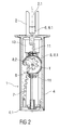
- Figure 2
- a longitudinal section of an exemplary embodiment of a needle assembly attachment and removal device in a third sectional plane, and
- Figure 3
- is a longitudinal section of an exemplary embodiment of a needle assembly attachment and removal device in the second sectional plane with a carriage in a depressed position.
- Corresponding parts are marked with the same reference symbols in all figures.
-
Figure 1A is a longitudinal section of a needle assembly attachment andremoval device 1 in a first sectional plane according to an exemplary embodiment of the present invention. Thedevice 1 is adapted to receive a medicament delivery device and to attach and remove aneedle assembly 6 to and from the delivery device. - In an exemplary embodiment, the delivery device (not illustrated) may be any medicament delivery device including, but not limited to, a pen injector, an auto-injector, a safety syringe, etc. The delivery device may include a cartridge holder adapted to hold a medicament-containing cartridge (not illustrated). As understood by those of skill in the art, the delivery device may be a single-use device (e.g., the delivery device is disposed of after the cartridge is empty) or a re-usable device (e.g., the cartridge may be replaced when empty or otherwise necessary).
- In an exemplary embodiment, the needle assembly includes a needle hub 6.2 adapted to engage the delivery device and a needle 6.3 which has a distal tip 6.4 and a proximal tip 6.5 coupled to the needle hub 6.2. The proximal tip 6.5 is arranged to pierce a septum of a cartridge in the delivery device when the
needle assembly 6 is mounted to the delivery device, and the distal tip 6.4 is used to pierce an injection site. When theneedle assembly 6 is coupled to the delivery device, the medicament can be displaced through a fluid channel within the needle 6.3. - In an exemplary embodiment, the needle hub 6.2 includes internal threads 6.6 for mating with threads formed on the delivery device. An inner needle cap 6.7 may be arranged over the needle 6.3. An outer cap 6.1 may be arranged over the needle hub 6.2, needle 6.3 and inner needle cap 6.7. The outer cap 6.1 may include features (e.g., grooves) which mate with corresponding features (e.g., ridges) on the needle hub 6.2, such that the outer cap 6.1 does not rotate relative to the needle hub 6.2 when they are engaged.
- In an exemplary embodiment, the needle assembly attachment and
removal device 1 comprises anelongate case 4 with a base 4.1 at a lower end. The base 4.1 may be planar to serve as a platform so that thedevice 1 may be placed on a surface during use. In an exemplary embodiment, the base 4.1 may be have a larger cross-section than thecase 4 to increase surface area and stability when placed on a surface. In addition, an underside of the base 4.1 may include a coating or matting adapted to frictionally engage a surface. An upper end of thecase 4 has an opening adapted to receive theneedle assembly 6 and the delivery device. - In an exemplary embodiment, the
device 1 includes aretainer 2 arranged on acarriage 11 which is slidably arranged within thecase 4 along a longitudinal axis L. Theretainer 2 may comprise a plurality of axial arms which have contoured internal surfaces adapted to support align the delivery device when it is inserted into thedevice 1. Theretainer 2 may ensure that the delivery device properly engages/disengages the needle assembly 6 (e.g., that the threads are aligned correctly). - In an exemplary embodiment, the
device 1 includes acarrier 13 rotatably coupled to thecarriage 11. Acap clamp 14 may be rotatably coupled to thecarrier 13 via a clutch 15 (which is keyed to the carriage 11). Thecap clamp 14 is adapted to engage the outer cap 6.1 of theneedle assembly 6.Resilient clamp arms 3 may be disposed at a lower end of thecap clamp 14. Aclamp ring 12 is disposed in thecarriage 11 and coupled to apush rod 5, which is slidably coupled to thecarriage 11. Theclamp ring 12 is adapted to engage theclamp arms 3 to push theclamp arms 3 into frictional engagement with the outer cap 6.1. Theclamp arms 3 may include a tapered surface 3.1 adapted to engage a corresponding tapered surface of theclamp ring 12. Theclamp arms 3 may deflect and frictionally engage the outer cap 6.1, as described further below. - In an exemplary embodiment, the clutch 15 includes a ratchet face adapted to engage a corresponding ratchet face on the
cap clamp 14. As explained further below, the clutch 15 limits an attachment torque applied to theneedle assembly 6 when theneedle assembly 6 is mounted on the delivery device. - In an exemplary embodiment, a
pinion 8 is rotatably coupled to thecarriage 11 and may include atorsion spring 9 applying a biasing force to thepinion 8. The pinion includes a first gear face 8.1 which is adapted to mate with a gear wheel 11.2 on thecarrier 13 and a second gear face 8.2 which is adapted to mate with arack 7 formed in thecase 4. Thus, rotation of thepinion 8 causes rotation of thecarrier 13. In an exemplary embodiment, therack 7 and the second gear face 8.2 form a rack and pinion arrangement having a variable transmission. Therack 7 may be arranged at an angle with respect to the longitudinal axis L so that a distance between therack 7 and the longitudinal axis L increases along at least a portion of the length of thecase 4 and is greatest near the base 4.1. To maintain engagement with therack 7, the second gear face 8.2 has a variable diameter. Thus, when thecarriage 11 is in or near the upper end of thecase 4, translation of thecarriage 11 causes low torque in thepinion 8 and high rotational speed, whereas translation near the low end of thecase 4 causes an increase in torque and a lower rotational speed. Thetorsion spring 9 may bias the pinion towards the upper end of thecase 4. - In an exemplary embodiment, the
carriage 11 includes acompression spring 10 adapted to engage a spring stop 4.2 disposed on the base 4.1. Thecompression spring 10 compresses as thecarriage 11 moves toward the base 4.1. - In an exemplary embodiment, the
carriage 11 includes a pin 11.3 adapted to engage a retaining groove 4.3 formed adjacent the base 4.1. As explained further below, the retaining groove 4.3 may include various positions for the pin 11.3 to maintain thecarriage 11 in a position relative to thecase 4. - As shown in
Figure 1 B , thecarriage 11 may include one or more guide wheels 11.1 adapted to engage one or more corresponding channels in thecase 4 for facilitating the axial movement of thecarriage 11 relative to thecase 4 and for maintaining an angular position of thecarriage 11 relative to thecase 4. -
Figures 1A ,1 B and2 show thedevice 1 in a pre-use state, in which thecarriage 11 is in a first axial position relative to thecase 4. In an exemplary embodiment, theneedle assembly 6 may be placed in thedevice 1 such that the outer cap 6.1 of theneedle assembly 6 engages thecap clamp 14. As theneedle assembly 6 is pushed into thecap clamp 14, thecap arms 3 may frictionally engage the outer cap 6.1 and/or theclamp ring 12 may prevent thecap arms 3 from deflecting and ensure a frictional hold on the outer cap 6.1. - To mount the needle hub 6.2 onto the delivery device, the delivery device is aligned with the needle aperture 2.1 of the
retainer 2, and theretainer 2 aligns the delivery device with the needle hub 6.2 in the needle assembly. As the delivery device is pressed into thedevice 1, thecarriage 11 translates towards the base 4.1. Because the second gear face 8.2 engages therack 7 and because the first gear face 8.1 engages the gear wheel 11.2, thecarrier 13 rotates in a first rotational direction as thecarriage 11 translates axially. As thecarrier 13 rotates, the cap clamp 14 (and outer cap 6.1 and needle hub 6.2) rotate in the first rotational direction so that the threads 6.6 on the needle hub 6.2 engage the threads on the delivery device. Due to the increasing diameter of the second gear face 8.2, the torque applied to the needle hub 6.2 increases as thecarriage 11 translates towards the base 4.1. As thecarriage 11 translates towards the base 4.1 and thepinion 8 rotates, thetorsion spring 9 is energized. - When the
carriage 11 is proximate the base 4.1, the pin 11.3 engages the retaining groove 4.3. The retaining groove 4.3 may have a first portion which is adapted to receive the pin 11.3 and deflect the pin 11.3 toward the longitudinal axis L. Thecompression spring 10 engages and compresses against the spring stop 4.2. Thepush rod 5 abuts the base 4.1 and further translation of thecarriage 11 causes theclamp ring 12 to engage theclamp arms 3 to secure the outer cap 6.1 in thecap clamp 14. - After the needle hub 6.2 has been properly secured to the delivery device, any further rotation of the
carrier 13 relative to the needle hub 6.2 may cause the clutch 15 to disengage thecap clamp 14. Thus, the clutch 15 prevents over-tightening the needle hub 6.2. When the clutch 15 disengages thecap clamp 14, an audible feedback (e.g., clicking of the slipping ratchet faces) may be provided to indicate that the needle hub 6.2 has been secured to the delivery device. - As shown in
Figure 3 , when the delivery device (with the needle hub 6.2 attached thereto) is removed from thedevice 1, thecarriage 11 is in a second axial position. Theclamp arms 3 and/or theclamp ring 12 may hold the outer cap 6.1 in thedevice 1, and the force in thetorsion spring 9 and/or the force in thecompression spring 10 may push thecarriage 11 away from the base 4.1. Due to the resilient force on the pin 11.3, the pin 11.3 moves to a second (locking) portion in the retaining groove 4.3. When the pin 11.3 is in the second portion, thecarriage 11 is prevented from further axial movement away from the base 4.1. - After an injection, the
device 1 may be used to remove the used needle hub 6.2. The delivery device may be reinserted into thedevice 1 by aligning with theretainer 2. A first tactile feedback (e.g., increased resistance) may be provided when the needle hub 6.2 engages the outer cap 6.1. When the delivery device is advanced into thedevice 1 and the needle hub 6.2 engages the outer cap 6.1, thecarriage 11 may be advanced toward the base 4.1 a small distance, and the pin 11.3 may disengage the second portion in the retaining groove 4.3 and resiliently deflect into a third portion, which may be a channel that does not obstruct axial movement of the pin 11.3 and allows thecarriage 11 to translate axially away from the base 4.1. The force in thetorsion spring 9 rotates thepinion 8 to climb up therack 7, and the force in thecompression spring 10 pushes thecarriage 11 away from the base 4.1. The rotation of thepinion 8 results in rotation of thecarrier 13 in a second rotational direction which disengages the needle hub 6.2 from the delivery device. - In an exemplary embodiment, the
compression spring 10 is primarily active in a first part of a demounting cycle, e.g., to generate high torque and high rotational speed on thecarrier 13 and thecap clamp 14 to loosen the thread 6.6 of the needle hub 6.2 from the threads on the delivery device. After thecarriage 11 has travelled a distance relative to thecase 4, thepush rod 5 no longer abuts the base 4.1 and thecompression spring 10 disengages the spring stop 4.2. The remaining rotational force on thecarriage 11 is supplied by thetorsion spring 9. After the needle hub 6.2 has been loosened from the delivery device, the torque of thetorsion spring 9 suffices to return the delivery device to the initial upper end position and unscrew the needle hub 6.2 from the delivery device. - After the needle hub 6.2 has disengaged the delivery device and the
carriage 11 returns to its initial position, theneedle assembly 6 may be grasped and removed from thedevice 1 for disposal. - In an exemplary embodiment, the
device 1 may include a locking mechanism (not shown) for locking thecarriage 11 relative to thecase 4. For example, the locking mechanism may be a lever which locks thecarriage 11 in a position (e.g., the second position) relative to thecase 4 or a cover disposed over the needle aperture 2.1. - Those of skill in the art will understand that modifications (additions and/or removals) of various components of the apparatuses, methods and/or systems and embodiments described herein may be made without departing from the full scope and spirit of the present invention, which encompass such modifications and any and all equivalents thereof.
Claims (15)
- A needle assembly attachment and removal device (1) comprising:a case (4) having a base (4.1) and a longitudinal axis (L);a carriage (11) axially movable with the case (4) from a first position to a second position;a carrier (13) rotatably coupled to the carriage (11) and adapted to hold a needle assembly (6); anda gearing arrangement (7, 8) rotatably coupled to the carriage (11) and adapted to rotate the carrier (13) in a first rotational direction as the carriage (11) moves from the first position to the second position and in a second rotational direction as the carriage (11) moves from the second position to the first position.
- The needle assembly attachment and removal device (1) according to claim 1, further comprising:a retainer (2) coupled to the case (4) or the carriage (11) or the carrier (13) and adapted to align a medicament delivery device with the needle assembly (6).
- The needle assembly attachment and removal device (1) according to any one of the preceding claims, wherein the base (4.1) has a larger cross-section than the case (4).
- The needle assembly attachment and removal device (1) according to any one of the preceding claims, further comprising:a cap clamp (14) coupled to the carrier (13) and adapted to engage an outer cap (6.1) of the needle assembly (6).
- The needle assembly attachment and removal device (1) according to claim 4, wherein the cap clamp (14) includes resilient clamp arms (3) adapted to engage a portion of the outer cap (6.1).
- The needle assembly attachment and removal device (1) according to claim 5, further comprising:a push rod (5) slidably coupled to the carriage (11); anda clamp ring (12) coupled to the push rod (5) and adapted to apply a compressive force on the clamp arms (3) to maintain engagement with the portion of the outer cap (6.1),wherein the push rod (5) urges the clamp ring (12) against the clamp arms (3) when the push rod (5) engages the base (4.1).
- The needle assembly attachment and removal device (1) according to any one of the preceding claims, wherein the gearing arrangement (7, 8) includes:a rack (7) disposed in the case (4); anda pinion (8) having a first gear face (8.1) adapted to engage a gear wheel (11.2) coupled to the carrier (13) and a second gear face (8.2) adapted to engage the rack (7).
- The needle assembly attachment and removal device (1) according to claim 7, wherein the rack (7) is disposed at an angle relative to the longitudinal axis (L) of the case (4), and the second gear face (8.2) has a variable diameter.
- The needle assembly attachment and removal device (1) according to claim 8, wherein the gearing arrangement (7, 8) further includes:a torsion spring (9) applying a rotational biasing force to the pinion (8), wherein movement of the carriage (11) from the first position to the second position causes the pinion (8) to rotate and energize the torsion spring (9).
- The needle assembly attachment and removal device (1) according to claim 9, wherein the carriage (11) rotates about the longitudinal axis (L) and a rotational axis (T) of the pinion (8) is orthogonal to the longitudinal axis (L).
- The needle assembly attachment and removal device (1) according to any one of the preceding claims, further comprising:a compression spring (10) adapted to engage a spring stop (4.2) formed on the base (4.1), the compression spring (10) being energized when the carriage (11) is in the second position.
- The needle assembly attachment and removal device (1) according to any one of the preceding claims, wherein the carriage (11) includes a resilient pin (11.3) adapted to engage a retaining groove (4.3) in the case (4), wherein as the carriage (11) moves from the first position to the second position, the pin (11.3) enters a first portion of the retaining groove (4.3) and deflects toward a longitudinal axis (L) of the case (4), and wherein when the pin (11.3) engages a second portion of the retaining groove (4.3), the carriage (11) is locked in the second position, and wherein when the pin (11.3) is engaged in the second portion of the retaining groove (4.3), an axial force on the carriage (11) directed toward the base (4.1) causes the pin (11.3) to disengage the second portion and enter a third portion of the retaining groove (4.3) which allows the carriage (11) to return to the first position.
- The needle assembly attachment and removal device (1) according to claims 11 and 12, wherein a force in the compression spring (10) propels the carriage (11) toward the first position when the pin (11.3) enters the third portion of the retaining groove (4.3).
- The needle assembly attachment and removal device (1) according to claim 5, further comprising:a clutch (15) disposed between the cap clamp (14) and the carrier (13), the clutch (15) preventing rotation of the cap clamp (14) relative to the carrier (13) in the first rotational direction until a predetermined torque is applied on the outer cap (6.1), and preventing rotation of the cap clamp (14) relative to the carrier (13) in the second rotational direction.
- The needle assembly attachment and removal device (1) according to any one of the preceding claims, wherein the carriage (11) includes guide wheels (11.1) adapted to engage channels formed in the base (4).
Priority Applications (18)
| Application Number | Priority Date | Filing Date | Title |
|---|---|---|---|
| EP11190581.6A EP2596825A1 (en) | 2011-11-24 | 2011-11-24 | Needle assembly attachment and removal device |
| CN201280067444.6A CN104053468B (en) | 2011-11-24 | 2012-11-23 | Needle assemblies attachment and apparatus for removing |
| BR112014012424A BR112014012424A2 (en) | 2011-11-24 | 2012-11-23 | needle assembly clamp and removal device |
| PL12794694.5T PL2782627T3 (en) | 2011-11-24 | 2012-11-23 | Needle assembly attachment and removal device |
| AU2012342447A AU2012342447A1 (en) | 2011-11-24 | 2012-11-23 | Needle assembly attachment and removal device |
| HK14110304.4A HK1196790B (en) | 2011-11-24 | 2012-11-23 | Needle assembly attachment and removal device |
| KR1020147016852A KR20140116071A (en) | 2011-11-24 | 2012-11-23 | Needle assembly attachment and removal device |
| RU2014125419/14A RU2014125419A (en) | 2011-11-24 | 2012-11-23 | DEVICE FOR CONNECTING AND REMOVING THE NEEDLE HOLDER |
| EP12794694.5A EP2782627B1 (en) | 2011-11-24 | 2012-11-23 | Needle assembly attachment and removal device |
| CA2856761A CA2856761A1 (en) | 2011-11-24 | 2012-11-23 | Needle assembly attachment and removal device |
| PCT/EP2012/073465 WO2013076244A1 (en) | 2011-11-24 | 2012-11-23 | Needle assembly attachment and removal device |
| US14/360,276 US9694143B2 (en) | 2011-11-24 | 2012-11-23 | Needle assembly attachment and removal device |
| HUE12794694A HUE029740T2 (en) | 2011-11-24 | 2012-11-23 | Needle assembly attachment and removal device |
| MX2014006283A MX2014006283A (en) | 2011-11-24 | 2012-11-23 | Needle assembly attachment and removal device. |
| ES12794694.5T ES2585081T3 (en) | 2011-11-24 | 2012-11-23 | Needle assembly and removal device |
| JP2014542849A JP6215218B2 (en) | 2011-11-24 | 2012-11-23 | Needle assembly attachment / detachment device |
| DK12794694.5T DK2782627T3 (en) | 2011-11-24 | 2012-11-23 | DEVICE FOR DETERMINATION AND REMOVAL OF MEASURING INSTALLATION |
| IL232695A IL232695A0 (en) | 2011-11-24 | 2014-05-19 | Needle assembly attachment and removal device |
Applications Claiming Priority (1)
| Application Number | Priority Date | Filing Date | Title |
|---|---|---|---|
| EP11190581.6A EP2596825A1 (en) | 2011-11-24 | 2011-11-24 | Needle assembly attachment and removal device |
Publications (1)
| Publication Number | Publication Date |
|---|---|
| EP2596825A1 true EP2596825A1 (en) | 2013-05-29 |
Family
ID=47278282
Family Applications (2)
| Application Number | Title | Priority Date | Filing Date |
|---|---|---|---|
| EP11190581.6A Ceased EP2596825A1 (en) | 2011-11-24 | 2011-11-24 | Needle assembly attachment and removal device |
| EP12794694.5A Not-in-force EP2782627B1 (en) | 2011-11-24 | 2012-11-23 | Needle assembly attachment and removal device |
Family Applications After (1)
| Application Number | Title | Priority Date | Filing Date |
|---|---|---|---|
| EP12794694.5A Not-in-force EP2782627B1 (en) | 2011-11-24 | 2012-11-23 | Needle assembly attachment and removal device |
Country Status (16)
| Country | Link |
|---|---|
| US (1) | US9694143B2 (en) |
| EP (2) | EP2596825A1 (en) |
| JP (1) | JP6215218B2 (en) |
| KR (1) | KR20140116071A (en) |
| CN (1) | CN104053468B (en) |
| AU (1) | AU2012342447A1 (en) |
| BR (1) | BR112014012424A2 (en) |
| CA (1) | CA2856761A1 (en) |
| DK (1) | DK2782627T3 (en) |
| ES (1) | ES2585081T3 (en) |
| HU (1) | HUE029740T2 (en) |
| IL (1) | IL232695A0 (en) |
| MX (1) | MX2014006283A (en) |
| PL (1) | PL2782627T3 (en) |
| RU (1) | RU2014125419A (en) |
| WO (1) | WO2013076244A1 (en) |
Cited By (4)
| Publication number | Priority date | Publication date | Assignee | Title |
|---|---|---|---|---|
| CN108543168A (en) * | 2018-05-15 | 2018-09-18 | 赵齐美 | The electronic provision for disengagement of portable insulin syringe needle |
| US10258746B2 (en) | 2014-03-25 | 2019-04-16 | Inventive Medical Devices, Llc | Apparatus and method of automatically removing a needle from a hub |
| CN112957556A (en) * | 2021-02-19 | 2021-06-15 | 杜绍芹 | Transfusion port puncture-wound-preventing fixer with protection positioning device |
| US11793607B2 (en) * | 2019-08-13 | 2023-10-24 | Bernhard Foerster Gmbh | Orthodontic expansion screw |
Families Citing this family (7)
| Publication number | Priority date | Publication date | Assignee | Title |
|---|---|---|---|---|
| USD748243S1 (en) * | 2013-08-06 | 2016-01-26 | Michael Perthu | Auto-injector |
| USD756507S1 (en) * | 2013-09-04 | 2016-05-17 | Michael Perthu | Auto-injector |
| EP3277348B1 (en) | 2015-03-31 | 2020-07-22 | Southern Innovationz Limited | Apparatus for unsheathing and resheathing a needle device |
| KR101589006B1 (en) * | 2015-10-17 | 2016-02-12 | 주식회사 메덱셀 | Safety protection system for pen needles |
| US11744957B2 (en) * | 2017-12-28 | 2023-09-05 | Embecta Corp. | Pen needle assembly apparatus |
| CN108992744B (en) * | 2018-06-29 | 2020-11-03 | 苏州沙力医疗器械有限公司 | Rotary locking type safe insulin injection needle |
| CN110732062B (en) * | 2019-08-02 | 2021-07-20 | 宁波市北仑区人民医院 | A push-down needle unloading device |
Citations (4)
| Publication number | Priority date | Publication date | Assignee | Title |
|---|---|---|---|---|
| US5312346A (en) * | 1993-02-16 | 1994-05-17 | Han Medical Designs, Inc. | Needle removing device |
| US5947950A (en) * | 1998-02-19 | 1999-09-07 | Med-Safe Systems, Inc. | Gear driven needle removal device |
| WO2010113388A1 (en) * | 2009-03-31 | 2010-10-07 | 株式会社みくに工業 | Container for collecting needle to be discarded and part for collecting needle to be discarded |
| WO2010124974A2 (en) * | 2009-04-30 | 2010-11-04 | Sanofi-Aventis Deutschland Gmbh | Needle remover and method for removing a needle |
Family Cites Families (12)
| Publication number | Priority date | Publication date | Assignee | Title |
|---|---|---|---|---|
| US4986811A (en) * | 1988-09-23 | 1991-01-22 | Post Medical, Inc. | Apparatus and method for safely removing needles from syringes |
| US5188598A (en) * | 1988-09-23 | 1993-02-23 | Post Medical, Inc. | Apparatus and method for safely disposing contaminated needles |
| US4989307A (en) * | 1989-05-11 | 1991-02-05 | Sharpe Kenneth M | Apparatus for facilitating of the removal and disposal of medical needles |
| JP2517521B2 (en) * | 1993-04-22 | 1996-07-24 | 節一 山口 | Removal and storage container for used injection needles |
| US5573113A (en) * | 1995-01-03 | 1996-11-12 | Med-Safe Systems, Inc. | Needle removal device for blood collection holders |
| US5741230A (en) * | 1996-07-31 | 1998-04-21 | Miller; Gary E. | Hypodermic needle extraction disposal system and device |
| US5791471A (en) * | 1997-08-01 | 1998-08-11 | Radmand; Reza | Dental sharps containment device and method of using the same "needle protection device" (NPD) |
| US20050121343A1 (en) * | 2003-09-18 | 2005-06-09 | Miller Gary E. | Hypodermic needle extraction and disposal system and device |
| GB2415141A (en) * | 2004-06-19 | 2005-12-21 | Stephen Francis Gerard Cooley | Medical needle removal device |
| JP2006187384A (en) * | 2005-01-04 | 2006-07-20 | Miyuki Morita | Device for removing injection needle |
| GB2460398A (en) * | 2008-05-20 | 2009-12-02 | Owen Mumford Ltd | Auto-injector having a magnetic injection indicator and a needle sheath retainer |
| EP2540329A1 (en) * | 2011-06-28 | 2013-01-02 | Sanofi-Aventis Deutschland GmbH | Needle assembly attachment and removal device |
-
2011
- 2011-11-24 EP EP11190581.6A patent/EP2596825A1/en not_active Ceased
-
2012
- 2012-11-23 CN CN201280067444.6A patent/CN104053468B/en not_active Expired - Fee Related
- 2012-11-23 AU AU2012342447A patent/AU2012342447A1/en not_active Abandoned
- 2012-11-23 EP EP12794694.5A patent/EP2782627B1/en not_active Not-in-force
- 2012-11-23 MX MX2014006283A patent/MX2014006283A/en unknown
- 2012-11-23 PL PL12794694.5T patent/PL2782627T3/en unknown
- 2012-11-23 ES ES12794694.5T patent/ES2585081T3/en active Active
- 2012-11-23 JP JP2014542849A patent/JP6215218B2/en not_active Expired - Fee Related
- 2012-11-23 WO PCT/EP2012/073465 patent/WO2013076244A1/en not_active Ceased
- 2012-11-23 DK DK12794694.5T patent/DK2782627T3/en active
- 2012-11-23 CA CA2856761A patent/CA2856761A1/en not_active Abandoned
- 2012-11-23 US US14/360,276 patent/US9694143B2/en not_active Expired - Fee Related
- 2012-11-23 BR BR112014012424A patent/BR112014012424A2/en not_active IP Right Cessation
- 2012-11-23 RU RU2014125419/14A patent/RU2014125419A/en not_active Application Discontinuation
- 2012-11-23 HU HUE12794694A patent/HUE029740T2/en unknown
- 2012-11-23 KR KR1020147016852A patent/KR20140116071A/en not_active Withdrawn
-
2014
- 2014-05-19 IL IL232695A patent/IL232695A0/en unknown
Patent Citations (4)
| Publication number | Priority date | Publication date | Assignee | Title |
|---|---|---|---|---|
| US5312346A (en) * | 1993-02-16 | 1994-05-17 | Han Medical Designs, Inc. | Needle removing device |
| US5947950A (en) * | 1998-02-19 | 1999-09-07 | Med-Safe Systems, Inc. | Gear driven needle removal device |
| WO2010113388A1 (en) * | 2009-03-31 | 2010-10-07 | 株式会社みくに工業 | Container for collecting needle to be discarded and part for collecting needle to be discarded |
| WO2010124974A2 (en) * | 2009-04-30 | 2010-11-04 | Sanofi-Aventis Deutschland Gmbh | Needle remover and method for removing a needle |
Cited By (5)
| Publication number | Priority date | Publication date | Assignee | Title |
|---|---|---|---|---|
| US10258746B2 (en) | 2014-03-25 | 2019-04-16 | Inventive Medical Devices, Llc | Apparatus and method of automatically removing a needle from a hub |
| CN108543168A (en) * | 2018-05-15 | 2018-09-18 | 赵齐美 | The electronic provision for disengagement of portable insulin syringe needle |
| CN108543168B (en) * | 2018-05-15 | 2023-10-17 | 赵齐美 | Portable insulin syringe needle electric dismounting device |
| US11793607B2 (en) * | 2019-08-13 | 2023-10-24 | Bernhard Foerster Gmbh | Orthodontic expansion screw |
| CN112957556A (en) * | 2021-02-19 | 2021-06-15 | 杜绍芹 | Transfusion port puncture-wound-preventing fixer with protection positioning device |
Also Published As
| Publication number | Publication date |
|---|---|
| BR112014012424A2 (en) | 2017-06-06 |
| CA2856761A1 (en) | 2013-05-30 |
| HK1196790A1 (en) | 2014-12-24 |
| ES2585081T3 (en) | 2016-10-03 |
| IL232695A0 (en) | 2014-07-31 |
| AU2012342447A1 (en) | 2014-06-19 |
| DK2782627T3 (en) | 2016-08-15 |
| EP2782627B1 (en) | 2016-04-27 |
| RU2014125419A (en) | 2015-12-27 |
| EP2782627A1 (en) | 2014-10-01 |
| JP2015501689A (en) | 2015-01-19 |
| US20140276443A1 (en) | 2014-09-18 |
| US9694143B2 (en) | 2017-07-04 |
| KR20140116071A (en) | 2014-10-01 |
| CN104053468B (en) | 2016-08-24 |
| MX2014006283A (en) | 2014-11-10 |
| PL2782627T3 (en) | 2016-11-30 |
| HUE029740T2 (en) | 2017-04-28 |
| CN104053468A (en) | 2014-09-17 |
| JP6215218B2 (en) | 2017-10-18 |
| WO2013076244A1 (en) | 2013-05-30 |
Similar Documents
| Publication | Publication Date | Title |
|---|---|---|
| US9694143B2 (en) | Needle assembly attachment and removal device | |
| US9283328B2 (en) | Needle assembly attachment and removal device | |
| EP2626096A1 (en) | Medicament delivery device with needle assembly removal mechanism | |
| EP2572745A1 (en) | Needle safety device | |
| EP2822620B1 (en) | Needle assembly removal device and disposal device | |
| JP2014516718A (en) | Needle assembly removal device | |
| HK1196790B (en) | Needle assembly attachment and removal device | |
| EP4135796A1 (en) | Pre-filled syringe system and method | |
| JP6074418B2 (en) | Needle assembly system | |
| HK1192174B (en) | Needle assembly attachment and removal device | |
| HK1192174A (en) | Needle assembly attachment and removal device | |
| HK1200387B (en) | Needle assembly removal device and disposal device |
Legal Events
| Date | Code | Title | Description |
|---|---|---|---|
| PUAI | Public reference made under article 153(3) epc to a published international application that has entered the european phase |
Free format text: ORIGINAL CODE: 0009012 |
|
| AK | Designated contracting states |
Kind code of ref document: A1 Designated state(s): AL AT BE BG CH CY CZ DE DK EE ES FI FR GB GR HR HU IE IS IT LI LT LU LV MC MK MT NL NO PL PT RO RS SE SI SK SM TR |
|
| AX | Request for extension of the european patent |
Extension state: BA ME |
|
| STAA | Information on the status of an ep patent application or granted ep patent |
Free format text: STATUS: THE APPLICATION HAS BEEN REFUSED |
|
| 18R | Application refused |
Effective date: 20130617 |