EP2595867B1 - Variable device for varying central axis of wheel - Google Patents
Variable device for varying central axis of wheel Download PDFInfo
- Publication number
- EP2595867B1 EP2595867B1 EP11809819.3A EP11809819A EP2595867B1 EP 2595867 B1 EP2595867 B1 EP 2595867B1 EP 11809819 A EP11809819 A EP 11809819A EP 2595867 B1 EP2595867 B1 EP 2595867B1
- Authority
- EP
- European Patent Office
- Prior art keywords
- cap
- rotating body
- central axis
- variable device
- interference
- Prior art date
- Legal status (The legal status is an assumption and is not a legal conclusion. Google has not performed a legal analysis and makes no representation as to the accuracy of the status listed.)
- Not-in-force
Links
Images



Classifications
-
- B—PERFORMING OPERATIONS; TRANSPORTING
- B62—LAND VEHICLES FOR TRAVELLING OTHERWISE THAN ON RAILS
- B62K—CYCLES; CYCLE FRAMES; CYCLE STEERING DEVICES; RIDER-OPERATED TERMINAL CONTROLS SPECIALLY ADAPTED FOR CYCLES; CYCLE AXLE SUSPENSIONS; CYCLE SIDECARS, FORECARS, OR THE LIKE
- B62K25/00—Axle suspensions
- B62K25/02—Axle suspensions for mounting axles rigidly on cycle frame or fork, e.g. adjustably
Definitions
- the present invention relates to a central axis variable device for varying the central axis of a wheel, which simplifies a configuration of the variable device to thereby reduce a production cost and which smoothens an eccentricity control conveniently.
- bicycle riding is receiving popularity from many people irrespective of men and women, the old and the young, and seasons until now from former days. Further, bicycle riding does not only play a role of a transportation vehicle, but also enables people to enjoy an exercising effect simultaneously. Thus, it is expected that the popularity of the bicycle riding will be kept continuously.
- bicycles are diversified in view of kinds and functions according to user's usage from general bicycles to mountain bicycles.
- this applicant developed a shaking bicycle that can double interest and momentum by changing form and composition of a general bicycle, and gained a Korean Patent Registration No. 10-0583013 (see also corresponding prior art document WO-A-2006046823 ) for an eccentricity device that is essential to embody the shaking bicycle.
- the eccentricity device is mounted on a wheel of a bicycle, to thereby help position of a wheel eccentric around a drive shaft.
- the wheel may be located at the center around the drive shaft, or may be eccentric from the drive shaft according to user's manipulation of the bicycle, to thus make the wheel eccentrically rotate and to thereby make a rider feel a ride comfort ascending and descending from surface of the ground.
- the eccentricity device for the conventional shaking bicycle has the following problems.
- a variable device for varying the central axis of a wheel comprising:
- the central axis variable device further comprises an interference unit that is formed in the rotating body and the first cap in order to interfere with free rotation of the rotating body.
- the central axis variable device further comprises a bent piece that is formed inwards from the rotating body along the border of one side of the rotating body, wherein the interference unit comprises: an interference groove that is formed at a position corresponding to each recess portion of the first uneven portion in the bent piece; and a leaf spring that is elastically supported on the inner surface of the first cap and is inserted into the interference groove.
- a separation preventive member is detachably formed in the inner surface of the first cap, and interferes with the bent piece, to thus prevent the rotating body and the first cap from being separated from each other.
- the central axis variable device further comprises a spring that elastically supports the inner surface of the first cap and the inner surface of the second cap with respect to each other, between the inner surface of the first cap and the inner surface of the second cap.
- a disc unit that can constrain power of a bicycle is provided at the outside of the second cap.
- the central axis variable device according to the present invention has the following effects.
- a coupling member that couples first and second caps includes a head portion on which a plurality of grooves are formed.
- An interference protrusion that is elastically provided into the plurality of grooves in the second cap, to thereby maximize a coupling force of the coupling member.
- a leaf spring is inserted in an interference groove formed in a rotating body, and is elastically supported on the inner surface of the first cap, to thereby interfere with free rotation of the rotating body.
- the present invention provides an effect of exactly guiding the position of the rotating body with which the second cap is combined.
- variable device for varying the central axis of a wheel (hereinafter referred to as a variable device) according to a preferred embodiment of the present invention will be described with reference to the accompanying drawings, that is, Figures 1 to 6 .
- variable device For convenience of explanation, an example that a variable device according to this invention is placed on a bicycle will be described below.
- variable device according to the present invention can be placed to all devices that are driven by a wheel or wheels, for example, a motorcycle etc., as well as a bicycle, and can be applied to all wheels without being limited to a front wheel or a rear wheel.
- Figure 1 is a side view showing a state where a central axis variable device of a wheel according to a preferred embodiment of the present invention is placed on a tail gear wheel of a bicycle.
- variable device controls a distance difference about distance between a central axis being a drive shaft "S" of a bicycle and the outer circumferential surface of a rear wheel of the bicycle, to thus play a role of making the rear wheel with respect to the ground roll uniformly or travel eccentrically.
- variable device includes a rotating body 100, a first cap 200, a second cap 300 and a coupling member 400.
- a rear wheel is mounted in the rotating body 100.
- a rim including a plurality of spokes are provided on the outer circumferential surface of the rotating body 100.
- the rotating body 100 is formed in a cylindrical shape, and both sides of the rotating body 100 is provided in a perforating state.
- a plurality of uneven portions are formed along the circumference of the inner circumferential surface of the rotating body 100.
- the uneven portions formed on the rotating body 100 are called a first uneven portion 110 for convenience of explanation.
- intervals between the uneven portions in the first uneven portion 110 are equally formed, and the concave and convex portions in the first uneven portion 110 are preferably formed eight in number, respectively.
- the rotating body 100 may be rotated by one-eighth rounds step by step, and a binding force of the rotating body 100 may be further strengthened due to a coupling with a second uneven portion to be later described.
- a bent piece 120 is formed along the border of one side of the rotating body 100.
- the bent piece 120 prevents the first cap 200 from being easily detached from the rotating body 100 by a separation preventive member to be described later.
- the detailed description of the bent piece 120 will follow.
- bent piece 120 is formed inwards from the rotating body 100 along the border of one side of the rotating body 100.
- a plurality of interference grooves 121 are formed along the circumference of the bent piece 120.
- the interference grooves 121 guide a correct position at the time of a mutual coupling between the rotating body 100 and the second cap 300.
- a leaf spring to be described later is disposed on the interference grooves 121, thereby preventing free rotation of the rotating body 100 and thus making a coupling of the second cap 300 easily performed.
- the interference grooves 121 are formed at the positions corresponding to the concave portions of the first uneven portion formed in the rotating body 100, respectively.
- the first cap 200 is formed at one side of the variable device, and is combined at one side of the rotating body 100.
- An eccentricity hole 210 and a coupling hole 220 are formed at the first cap 200, which communicate with an inner side of the rotating body 100.
- a shaft tube 320 for coupling the drive shaft "S" of a bicycle passes through the eccentricity hole 210.
- the eccentricity hole 210 is formed at a position eccentric from the center of the first cap 200.
- the coupling member 400 that combines the first cap 200 and the second cap 300 at both sides of the rotating body 100 passes through a coupling hole 220.
- leaf springs 230 that are elastically supported are provided at the inner surface of the first cap 200.
- Each leaf spring 230 interfere with the rotating body 100 so that the rotating body 100 does not freely rotate on the first cap 200, and is inserted into a corresponding interference groove 121 of the rotating body 100.
- the center of the leaf spring 230 is inserted into the interference groove 121 so that rotation of the rotating body 100 is interfered. Accordingly, position of the second cap 300 can be guided correctly as a technological characteristic of the present invention.
- the leaf springs 230 are mounted to be opposite each other on the inner surface of the first cap 200.
- both ends of each leaf spring 230 are preferably placed on a pair of supports 231
- each leaf spring 230 is preferably bent in a form corresponding to the interference groove 121 of the rotating body 100.
- an engagement boss 200a of Figure 5a or 5b is formed on the inner surface of the first cap 200, and a separation preventive member 240 is detachably combined with the engagement boss 200a.
- the separation preventive member 240 prevents the first cap 200 from being separated from the rotating body 100.
- the first cap 200 is caught by the bent piece 120 of the rotating body 100 to thus avoid the first cap 200 from being detached from the rotating body 100.
- the engagement boss 200a is preferably formed between the supports 231, and the separation preventive member 240 is made in a form of interfering the bent piece 120 of the rotating body 100 at a state of being combined with the engagement boss 200a.
- the second cap 300 is combined with the other side of the rotating body 100, in order to form the variable device of the present invention.
- a second uneven portion 310 is formed along the circumference of the outer circumferential surface of the second cap 300.
- the second uneven portion 310 corresponds to the first uneven portion 110 of the rotating body 100, and the number of the respective concave and convex portions of the second uneven portion 310 is eight as in the case of the first uneven portion 110.
- the shaft tube 320 with which the drive shaft "S" of a bicycle is coupled and an engagement hole 330 through which the coupling member 400 is coupled are formed on the second cap 300.
- the shaft tube 320 is extended from the inner surface of the second cap 300, and is exposed to the outside through the eccentricity hole 210.
- the coupling member 400 passes through the engagement hole 330, and the engagement hole 330 corresponds to the coupling hole 220.
- the engagement hole 330 is perforated to the outside of the second cap 300.
- a step groove 340 that is formed with a step by the engagement hole 330 is formed at the outer surface of the second cap 300.
- a head portion of a coupling member 400 to be described later is arranged in the step groove 340.
- an interference projection 341 that is projected toward the step groove 340, is provided in the step groove 340.
- the interference protrusion 341 interferes with the head portion of the coupling member 400, to thereby prevent a coupling force of the coupling member 400 from being loosened.
- the interference protrusion 341 is provided at the inner side of the second cap 300 to have an elastic force, and can come in and out with the elastic force toward the step groove 340.
- a disc unit "D" is placed as a brake unit on the outer side of the second cap 300.
- a disc unit "D" is placed as a brake unit in the variable device according to this invention.
- a mounting protrusion 350 on which the disc unit "D" is placed is further formed on the outer surface of the second cap 300.
- a throughhole 351 that communicates with the inner portion of the shaft tube 320 is formed in the mounting protrusion 350.
- a plurality of screw holes 351a through which the disc unit "D" is screw-coupled are formed on the circumference of the throughhole 351.
- the coupling elements 400 plays a role of combining the first cap 200 and the second cap 300 with each other at both sides of the rotating body 100, and includes a head portion 410 and a thread portion 420.
- the head portion 410 is arranged in the step groove 340 of the second cap 300, and the thread part 420 is exposed into the coupling hole 220 of the first cap 200 through the engagement hole 330.
- a plurality of grooves 411 are formed along the circumference of the head portion 410.
- the grooves 411 are regions through the interference protrusion 341 that comes in and out from the step groove 340 is arranged. If the interference protrusion 341 is arranged into one of the grooves 411, the head portion 410 does not rotate. As a result, the coupling member 400 does not loosen.
- the thread portion 420 is extended from the head portion 410, and is exposed through the coupling hole 220 of the first cap 200, to then be engaged by a nut.
- a spring 500 is provided in the inner side of the rotating body 100, and both end portions of the spring 500 elastically supports the inner surface of the first cap 200 and the second cap 300, respectively.
- the spring 500 makes the second uneven portion 310 of the second cap 300 not lean to either side thereof but be pushed out evenly in a process of separating the second uneven portion 310 of the second cap 300 from the first uneven portion 110 of the rotating body 100 to make the rotating body 100 rotate.
- the first cap 200 is combined at one side of the rotating body 100.
- the center of the leaf spring 230 mounted on the inner surface of the first cap 200 is inserted into the interference groove 121 that is formed in the bent piece 120 of the rotating body 100.
- the rotating body 100 does not freely rotate by interference of the leaf spring 230.
- the separation preventive member 240 is combined with the engagement boss of the first cap 200.
- the separation preventive member 240 interferes with the bent piece 120 of the rotating body 100, thereby preventing the first cap 200 from being detached from the rotating body 100 even before the first cap 200 is coupled by the coupling member 400.
- This state can be seen as a temporary assembly of the first cap 200 with respect to the rotating body 100.
- the spring 500 is arranged in the inner side of the first cap 200 and then the first cap 200 is covered with the second cap 300. Then, the second cap 300 is combined at the other side of the rotating body 100.
- the second cap 300 is arranged at the other side of the rotating body 100 while having an elastic force.
- the coupling member 400 is made to pass through the engagement hole 330 of the second cap 300 and the coupling hole 220 of the first cap 200 and then is engaged by a nut.
- the head portion 410 of the coupling member 400 is arranged in the step groove 340, and an interference protrusion 341 is arranged in one of the grooves 411 of the head portion 410, to thereby prevent the coupling member 400 from loosening.
- a special tool for turning the head portion 410 is used to turn the coupling member 400.
- a socket wrench (not shown) is used as the special tool.
- the interference protrusion 341 that is withdrawn into the step groove 340 is pushed out into the inner side of the second cap 300 by the socket wrench, in a process of inserting the socket wrench into the step groove 340.
- the head portion 410 is turned using the socket wrench, to thereby tighten or loosen the coupling member 400.
- the socket wrench is separated from the head portion 410.
- the interference protrusion 341 is inserted into one of the grooves 411 of the head portion 410 by a restoring force, to thereby prevent the coupling member 400 from loosening.
- the disc unit "D" is made to correspond to screw holes 351a of the mounting protrusion 350, and then is combined with the mounting protrusion 350, using special bolts and so on.
- the coupling member 400 is loosened so that the coupling force of the first cap 200 and the second cap 300 decreases slowly.
- the second cap 300 starts to be pushed out evenly from the rotating body 100 by the elastic force of the spring that has supported the first cap 200 and the second cap 300.
- the rotating body 100 may be rotated by one-eighth rounds at a time.
- the rotating body 100 is elastically supported by the leaf spring 230, it is not rotated excessively.
- the rotating body 100 can rotate step by step.
- position of the rear wheel mounted on the rotating body 100 is also variable around the drive shaft "S.”
- the wheel central axis variable device according to the present invention can be made into a simple composition to thus reduce a production cost. Further, an eccentricity position of the rotating body can be simply varied.
- a central axis variable device for varying the central axis of a wheel according to the present invention can be applied in a leisure sports field using a variety of bicycles from a general bicycle to a mountain bicycle.
Landscapes
- Engineering & Computer Science (AREA)
- Mechanical Engineering (AREA)
- Transmission Devices (AREA)
- Steering Devices For Bicycles And Motorcycles (AREA)
- Axle Suspensions And Sidecars For Cycles (AREA)
- Seats For Vehicles (AREA)
- Motorcycle And Bicycle Frame (AREA)
Description
- The present invention relates to a central axis variable device for varying the central axis of a wheel, which simplifies a configuration of the variable device to thereby reduce a production cost and which smoothens an eccentricity control conveniently.
- People today are highly interested in leisure activities. Accordingly, they are also highly interested in leisure sports.
- Bicycle riding, in-line skating, etc., are most popular representative leisure sports.
- Among them, bicycle riding is receiving popularity from many people irrespective of men and women, the old and the young, and seasons until now from former days. Further, bicycle riding does not only play a role of a transportation vehicle, but also enables people to enjoy an exercising effect simultaneously. Thus, it is expected that the popularity of the bicycle riding will be kept continuously.
- Here, bicycles are diversified in view of kinds and functions according to user's usage from general bicycles to mountain bicycles.
- That is, various kinds and transforms of equipment for leisure sports are required according to a modem life that is changing variously and quickly.
- For this, this applicant developed a shaking bicycle that can double interest and momentum by changing form and composition of a general bicycle, and gained a Korean Patent Registration No.
10-0583013 WO-A-2006046823 ) for an eccentricity device that is essential to embody the shaking bicycle. - As can be seen from this, the eccentricity device is mounted on a wheel of a bicycle, to thereby help position of a wheel eccentric around a drive shaft.
- Accordingly, the wheel may be located at the center around the drive shaft, or may be eccentric from the drive shaft according to user's manipulation of the bicycle, to thus make the wheel eccentrically rotate and to thereby make a rider feel a ride comfort ascending and descending from surface of the ground.
- However, the eccentricity device for the conventional shaking bicycle has the following problems.
- First, a manufacturing process is difficult because of complicated composition, and a production cost increases due to an increase in man power during production.
- That is, since a screw and plural uneven portions are formed in a rotating frame and a circular shape control member respectively, and a latch is configured in the con- ventional art, a production cost is high.
- Second, as described above, since the rotating frame and the circular shape control member are combined with each other using a screw, and the uneven portions that have been engaged with each other secede from each other according to loosening of the screw coupling, the composition and method are very complicated and burdensome.
- To solve the above problems of the conventional art, it is an object of the present invention to provide a central axis variable device for varying the central axis of a wheel, which simplifies a configuration of the variable device to thereby reduce a production cost and which controls an eccentricity position of the wheel conveniently and accurately step by step.
- To accomplish the object of the present invention, there is provided a variable device for varying the central axis of a wheel, the central axis variable device comprising:
- a rotating body along the inner circumference of which a first uneven portion is formed and both sides of which are pierced with respect to each other;
- a first cap that is combined at one side of the rotating body, and on the eccentric portion of which an eccentricity hole is formed;
- a second cap along the outer circumference of which a second uneven portion is formed in correspondence to the first uneven portion to thus be combined at the other side of the rotating body, and on which a shaft tube that is inserted into the eccentricity hole is formed;
- wherein a coupling hole is formed at the first cap, an engagement hole corresponding to the coupling hole is formed at the second cap, and a coupling member passes through the coupling hole and the engagement hole and couples the first and second caps with each other, wherein a bent piece is formed inwards from the rotating body along the border of one side of the rotating body; wherein a separation preventive member is detachably formed in the inner surface of the first cap, and that interferes with the bent piece to thus prevent the rotating body and the first cap from being separated from each other;
- wherein a step groove is stepped toward the engagement hole and that is formed at the side of the second cap; and
- wherein an interference protrusion has an elastic force to come in and out toward the step groove and is formed in the inner side of the second cap,
- wherein the coupling member comprises a head portion on which a plurality of grooves are formed so that the interference protrusion is arranged into one of the plurality of grooves, and wherein a thread portion is extended from the head portion and is exposed through the coupling hole of the first cap to then be engaged by a nut.
- Preferably but not necessarily, the central axis variable device further comprises an interference unit that is formed in the rotating body and the first cap in order to interfere with free rotation of the rotating body.
- Preferably but not necessarily, the central axis variable device further comprises a bent piece that is formed inwards from the rotating body along the border of one side of the rotating body, wherein the interference unit comprises: an interference groove that is formed at a position corresponding to each recess portion of the first uneven portion in the bent piece; and a leaf spring that is elastically supported on the inner surface of the first cap and is inserted into the interference groove.
- Preferably but not necessarily, a separation preventive member is detachably formed in the inner surface of the first cap, and interferes with the bent piece, to thus prevent the rotating body and the first cap from being separated from each other.
- Preferably but not necessarily, the central axis variable device further comprises a spring that elastically supports the inner surface of the first cap and the inner surface of the second cap with respect to each other, between the inner surface of the first cap and the inner surface of the second cap.
- Preferably but not necessarily, a disc unit that can constrain power of a bicycle is provided at the outside of the second cap.
- The central axis variable device according to the present invention has the following effects.
- First, a composition of the central axis variable device is simplified and a production cost thereof is reduced. In addition, a series of processes that control eccentricity position of a wheel is simple.
- Second, a coupling member that couples first and second caps includes a head portion on which a plurality of grooves are formed. An interference protrusion that is elastically provided into the plurality of grooves in the second cap, to thereby maximize a coupling force of the coupling member.
- Third, a leaf spring is inserted in an interference groove formed in a rotating body, and is elastically supported on the inner surface of the first cap, to thereby interfere with free rotation of the rotating body.
- That is, a flow of the rotating body is prevented to thus provide a temporary assembly state. Accordingly, the present invention provides an effect of exactly guiding the position of the rotating body with which the second cap is combined.
- Fourth, since a separation preventive member that interferes with bent piece of the rotating body is detachably formed in the inner surface of the first cap, there is an effect that the first cap is not easily detached from the rotating body.
- Fifth, since a spring that elastically supports the inner surface of the first cap and the inner surface of the second cap with respect to each other, is provided between the inner surface of the first cap and the inner surface of the second cap, there is an effect of making the second cap pushed out evenly by the elastic force of the spring in a process that the second cap is pushed out from the rotating body when a coupling force of a coupling member is loosened.
- Accordingly, since the corresponding positions in the rotating body and the second cap are not loose, they can be reunited smoothly.
- The above and other objects and advantages of the present invention will become more apparent by describing the preferred embodiment thereof in detail with reference to the accompanying drawings in which:
-
Figure 1 is a side view showing a state where a central axis variable device of a wheel according to a preferred embodiment of the present invention is placed on a tail gear wheel of a bicycle; -
Figure 2 is an exploded perspective view showing a disjointed state of a central axis variable device of a wheel according to a preferred embodiment of this invention; -
Figure 3a shows left-hand, lateral and right-hand views of a rotating body of a central axis variable device of a wheel according to a preferred embodiment of this invention; -
Figure 3b shows left-hand, lateral and right-hand views of a first cap of a central axis variable device of a wheel according to a preferred embodiment of this invention; -
Figure 3c shows left-hand, lateral and right-hand views of a second cap of a central axis variable device of a wheel according to a preferred embodiment of this invention; -
Figure 4 is a perspective view showing a coupling member of a central axis variable device of a wheel according to a preferred embodiment of this invention; -
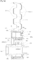
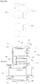
Figures 5a and5b are a cross-sectional view showing tightening and loosening of a first cap and a second cap of a central axis variable device of a wheel according to a preferred embodiment of this invention; and -
Figure 6 is a perspective view showing a coupled state of a central axis variable device of a wheel according to a preferred embodiment of this invention. - Hereinbelow, a variable device for varying the central axis of a wheel (hereinafter referred to as a variable device) according to a preferred embodiment of the present invention will be described with reference to the accompanying drawings, that is,
Figures 1 to 6 . - For convenience of explanation, an example that a variable device according to this invention is placed on a bicycle will be described below.
- However, the variable device according to the present invention can be placed to all devices that are driven by a wheel or wheels, for example, a motorcycle etc., as well as a bicycle, and can be applied to all wheels without being limited to a front wheel or a rear wheel.
-
Figure 1 is a side view showing a state where a central axis variable device of a wheel according to a preferred embodiment of the present invention is placed on a tail gear wheel of a bicycle. - Here, the variable device controls a distance difference about distance between a central axis being a drive shaft "S" of a bicycle and the outer circumferential surface of a rear wheel of the bicycle, to thus play a role of making the rear wheel with respect to the ground roll uniformly or travel eccentrically.
- That is, since a distance difference is kept between a drive shaft "S" and the outer circumferential surface that contacts the ground of a rear wheel, position of the drive shaft "S" around the center of the rear wheel is kept eccentric to thus vary a rolling function of the rear wheel.
- Since the function of the above-described variable device is disclosed in the Korean Patent Registration No.
10-0583013 - Hereinbelow, composition and function of the variable device according to a preferred embodiment of this invention will be described with reference to
Figures 2 through 6 . - As illustrated in
Figure 2 , the variable device includes arotating body 100, afirst cap 200, asecond cap 300 and acoupling member 400. - A rear wheel is mounted in the
rotating body 100. A rim including a plurality of spokes are provided on the outer circumferential surface of therotating body 100. - Here, the
rotating body 100 is formed in a cylindrical shape, and both sides of therotating body 100 is provided in a perforating state. - Here, a plurality of uneven portions are formed along the circumference of the inner circumferential surface of the
rotating body 100. - Here, the uneven portions formed on the
rotating body 100 are called a firstuneven portion 110 for convenience of explanation. - Here, intervals between the uneven portions in the first
uneven portion 110 are equally formed, and the concave and convex portions in the firstuneven portion 110 are preferably formed eight in number, respectively. - Accordingly, the
rotating body 100 may be rotated by one-eighth rounds step by step, and a binding force of therotating body 100 may be further strengthened due to a coupling with a second uneven portion to be later described. - As illustrated in
Figure 3a , abent piece 120 is formed along the border of one side of therotating body 100. - The
bent piece 120 prevents thefirst cap 200 from being easily detached from therotating body 100 by a separation preventive member to be described later. The detailed description of thebent piece 120 will follow. - Here, the
bent piece 120 is formed inwards from therotating body 100 along the border of one side of therotating body 100. - As can be seen from
Figure 3a , a plurality ofinterference grooves 121 are formed along the circumference of thebent piece 120. - The
interference grooves 121 guide a correct position at the time of a mutual coupling between therotating body 100 and thesecond cap 300. A leaf spring to be described later is disposed on theinterference grooves 121, thereby preventing free rotation of therotating body 100 and thus making a coupling of thesecond cap 300 easily performed. - Here, the
interference grooves 121 are formed at the positions corresponding to the concave portions of the first uneven portion formed in therotating body 100, respectively. - The
first cap 200 is formed at one side of the variable device, and is combined at one side of therotating body 100. - An
eccentricity hole 210 and acoupling hole 220 are formed at thefirst cap 200, which communicate with an inner side of therotating body 100. - A
shaft tube 320 for coupling the drive shaft "S" of a bicycle passes through theeccentricity hole 210. Theeccentricity hole 210 is formed at a position eccentric from the center of thefirst cap 200. - The
coupling member 400 that combines thefirst cap 200 and thesecond cap 300 at both sides of therotating body 100 passes through acoupling hole 220. - Meanwhile, as shown in
Figure 3b ,leaf springs 230 that are elastically supported are provided at the inner surface of thefirst cap 200. - Each
leaf spring 230 interfere with therotating body 100 so that therotating body 100 does not freely rotate on thefirst cap 200, and is inserted into acorresponding interference groove 121 of therotating body 100. - That is, the center of the
leaf spring 230 is inserted into theinterference groove 121 so that rotation of therotating body 100 is interfered. Accordingly, position of thesecond cap 300 can be guided correctly as a technological characteristic of the present invention. - The leaf springs 230 are mounted to be opposite each other on the inner surface of the
first cap 200. - Here, both ends of each
leaf spring 230 are preferably placed on a pair ofsupports 231 - Here, the center of each
leaf spring 230 is preferably bent in a form corresponding to theinterference groove 121 of therotating body 100. - Meanwhile, an
engagement boss 200a ofFigure 5a or5b is formed on the inner surface of thefirst cap 200, and a separationpreventive member 240 is detachably combined with theengagement boss 200a. - The separation
preventive member 240 prevents thefirst cap 200 from being separated from therotating body 100. - In more detail, even at a state where the
first cap 200 is not coupled by thecoupling member 400, thefirst cap 200 is caught by thebent piece 120 of therotating body 100 to thus avoid thefirst cap 200 from being detached from therotating body 100. - For this, the
engagement boss 200a is preferably formed between thesupports 231, and the separationpreventive member 240 is made in a form of interfering thebent piece 120 of therotating body 100 at a state of being combined with theengagement boss 200a. - Next, the
second cap 300 is combined with the other side of therotating body 100, in order to form the variable device of the present invention. A seconduneven portion 310 is formed along the circumference of the outer circumferential surface of thesecond cap 300. - The second
uneven portion 310 corresponds to the firstuneven portion 110 of therotating body 100, and the number of the respective concave and convex portions of the seconduneven portion 310 is eight as in the case of the firstuneven portion 110. - The
shaft tube 320 with which the drive shaft "S" of a bicycle is coupled and anengagement hole 330 through which thecoupling member 400 is coupled are formed on thesecond cap 300. - The
shaft tube 320 is extended from the inner surface of thesecond cap 300, and is exposed to the outside through theeccentricity hole 210. - In addition, the
coupling member 400 passes through theengagement hole 330, and theengagement hole 330 corresponds to thecoupling hole 220. - Here, the
engagement hole 330 is perforated to the outside of thesecond cap 300. Astep groove 340 that is formed with a step by theengagement hole 330 is formed at the outer surface of thesecond cap 300. - A head portion of a
coupling member 400 to be described later is arranged in thestep groove 340. - Here, as illustrated in
Figure 3c , aninterference projection 341 that is projected toward thestep groove 340, is provided in thestep groove 340. - The
interference protrusion 341 interferes with the head portion of thecoupling member 400, to thereby prevent a coupling force of thecoupling member 400 from being loosened. - The
interference protrusion 341 is provided at the inner side of thesecond cap 300 to have an elastic force, and can come in and out with the elastic force toward thestep groove 340. - Meanwhile, a disc unit "D" is placed as a brake unit on the outer side of the
second cap 300. - That is, as illustrated in
Figures 2 through 6 , a disc unit "D" is placed as a brake unit in the variable device according to this invention. - For this, a mounting
protrusion 350 on which the disc unit "D" is placed is further formed on the outer surface of thesecond cap 300. - A throughhole 351 that communicates with the inner portion of the
shaft tube 320 is formed in the mountingprotrusion 350. A plurality ofscrew holes 351a through which the disc unit "D" is screw-coupled are formed on the circumference of thethroughhole 351. - Next, the
coupling elements 400 plays a role of combining thefirst cap 200 and thesecond cap 300 with each other at both sides of therotating body 100, and includes ahead portion 410 and athread portion 420. - The
head portion 410 is arranged in thestep groove 340 of thesecond cap 300, and thethread part 420 is exposed into thecoupling hole 220 of thefirst cap 200 through theengagement hole 330. - Here, as illustrated in
Figure 4 , a plurality ofgrooves 411 are formed along the circumference of thehead portion 410. - The
grooves 411 are regions through theinterference protrusion 341 that comes in and out from thestep groove 340 is arranged. If theinterference protrusion 341 is arranged into one of thegrooves 411, thehead portion 410 does not rotate. As a result, thecoupling member 400 does not loosen. - In addition, the
thread portion 420 is extended from thehead portion 410, and is exposed through thecoupling hole 220 of thefirst cap 200, to then be engaged by a nut. - Meanwhile, a
spring 500 is provided in the inner side of therotating body 100, and both end portions of thespring 500 elastically supports the inner surface of thefirst cap 200 and thesecond cap 300, respectively. - The
spring 500 makes the seconduneven portion 310 of thesecond cap 300 not lean to either side thereof but be pushed out evenly in a process of separating the seconduneven portion 310 of thesecond cap 300 from the firstuneven portion 110 of therotating body 100 to make therotating body 100 rotate. - Hereinbelow, coupling and action of the variable device constructed above will be described.
- First, the
first cap 200 is combined at one side of therotating body 100. - Here, the center of the
leaf spring 230 mounted on the inner surface of thefirst cap 200 is inserted into theinterference groove 121 that is formed in thebent piece 120 of therotating body 100. - Accordingly, the
rotating body 100 does not freely rotate by interference of theleaf spring 230. - Then, the separation
preventive member 240 is combined with the engagement boss of thefirst cap 200. - Here, as illustrated in
Figures 5a and5b , the separationpreventive member 240 interferes with thebent piece 120 of therotating body 100, thereby preventing thefirst cap 200 from being detached from therotating body 100 even before thefirst cap 200 is coupled by thecoupling member 400. - This state can be seen as a temporary assembly of the
first cap 200 with respect to therotating body 100. - Next, the
spring 500 is arranged in the inner side of thefirst cap 200 and then thefirst cap 200 is covered with thesecond cap 300. Then, thesecond cap 300 is combined at the other side of therotating body 100. - Here, the
second cap 300 is arranged at the other side of therotating body 100 while having an elastic force. - Next, the
coupling member 400 is made to pass through theengagement hole 330 of thesecond cap 300 and thecoupling hole 220 of thefirst cap 200 and then is engaged by a nut. - Here, the
head portion 410 of thecoupling member 400 is arranged in thestep groove 340, and aninterference protrusion 341 is arranged in one of thegrooves 411 of thehead portion 410, to thereby prevent thecoupling member 400 from loosening. - Here, a special tool for turning the
head portion 410 is used to turn thecoupling member 400. A socket wrench (not shown) is used as the special tool. - That is, the
interference protrusion 341 that is withdrawn into thestep groove 340 is pushed out into the inner side of thesecond cap 300 by the socket wrench, in a process of inserting the socket wrench into thestep groove 340. - Accordingly, the
head portion 410 is turned using the socket wrench, to thereby tighten or loosen thecoupling member 400. - Thereafter, if tightening or loosening of the
coupling member 400 is ended, the socket wrench is separated from thehead portion 410. - Here, the
interference protrusion 341 is inserted into one of thegrooves 411 of thehead portion 410 by a restoring force, to thereby prevent thecoupling member 400 from loosening. - Then, the disc unit "D" that is a brake unit is combined with the mounting
protrusion 350. - As illustrated in
Figure 6 , the disc unit "D" is made to correspond to screwholes 351a of the mountingprotrusion 350, and then is combined with the mountingprotrusion 350, using special bolts and so on. - As described above, the coupling of the variable device is completed.
- Meanwhile, section of the combined variable device as described above is illustrated in
Figure 5a . - In this state, in order to make position of the rear wheel eccentric around the drive shaft "S" or the eccentric rear wheel restored into a correct position, the first
uneven portion 110 and the seconduneven portion 310 are uncoupled with each other and then therotating body 100 is made to rotate. - For this, the
coupling member 400 is loosened so that the coupling force of thefirst cap 200 and thesecond cap 300 decreases slowly. - Here, the
second cap 300 starts to be pushed out evenly from therotating body 100 by the elastic force of the spring that has supported thefirst cap 200 and thesecond cap 300. - Accordingly, engagement of the first
uneven portion 110 and the seconduneven portion 310 is released, to thereby enable therotating body 100 to rotate as illustrated inFigure 5b . - Here, since the concave and convex portions in the first
uneven portion 110 and the seconduneven portion 310 are formed eight in number, respectively, therotating body 100 may be rotated by one-eighth rounds at a time. - Here, since the
rotating body 100 is elastically supported by theleaf spring 230, it is not rotated excessively. - That is, since the
interference groove 121 formed in thebent piece 120 of therotating body 100 is shifted one by one, while holding theleaf spring 230, therotating body 100 can rotate step by step. - Thus, as the
rotating body 100 rotates step by step, position of the rear wheel mounted on therotating body 100 is also variable around the drive shaft "S." - That is, since the
rotating body 100 is variable around the drive shaft "S," that is, position of rear wheel is variable eccentrically, a rolling action of the rear wheel with respect to the ground is made irregularly. - As described above, the wheel central axis variable device according to the present invention can be made into a simple composition to thus reduce a production cost. Further, an eccentricity position of the rotating body can be simply varied.
- As described above, a central axis variable device for varying the central axis of a wheel according to the present invention can be applied in a leisure sports field using a variety of bicycles from a general bicycle to a mountain bicycle.
Claims (5)
- A central axis variable device for varying the central axis of a wheel, the central axis variable device comprising:a rotating body (100) along the inner circumference of which a first uneven portion (110) is formed and both sides of which are pierced with respect to each other;a first cap (200) that is combined at one side of the rotating body (100); a second cap (300) along the outer circumference of which a second uneven portion (310) is formed in correspondence to the first uneven portion (110) to thus be combined at the other side of the rotating body (100), and on which a shaft tube (320) is formed;characterized in that an eccentricity hole (210) is formed on an eccentric portion of the first cap (200);that the shaft tube (320) is inserted into the eccentricity hole (210);that a coupling hole (220) is formed at the first cap (200), an engagement hole (330) corresponding to the coupling hole (220) is formed at the second cap (300), and that a coupling member (400) passes through the coupling hole (220) and the engagement hole (330) and couples the first and second caps (200, 300) with each other,that a bent piece (120) is formed inwards from the rotating body (100) along the border of one side of the rotating body (100);that a separation preventive member (240) is detachably formed in the inner surface of the first cap (200), and that interferes with the bent piece (120), to thus prevent the rotating body (100) and the first cap (200) from being separated from each other;that a step groove (340) is stepped toward the engagement hole (330) and is formed at the side of the second cap (300); andthat an interference protrusion (341) has an elastic force to come in and out toward the step groove (340) and is formed in the inner side of the second cap (300),wherein the coupling member (400) comprises a head portion (410) on which a plurality of grooves (411) are formed so that the interference protrusion (341) is arranged into one of the plurality of grooves (411), and that a thread portion (420) is extended from the head portion (410), and is exposed through the coupling hole (220) of the first cap (200), to then be engaged by a nut.
- The central axis variable device according to claim 1, further comprising an interference unit that is formed in the rotating body (100) and the first cap (200) in order to interfere with free rotation of the rotating body (100).
- The central axis variable device according to claim 2, wherein the interference unit comprises:an interference groove (121) that is formed at a position corresponding to each recess portion of the first uneven portion (110) in the bent piece (120); anda leaf spring (230) that is elastically supported on the inner surface of the first cap (200) and is inserted into the interference groove (121).
- The central axis variable device according to any one of claims 1 to 3, further comprising a spring (500) that elastically supports the inner surface of the first cap (200) and the inner surface of the second cap (300) with respect to each other, between the inner surface of the first cap (200) and the inner surface of the second cap (300).
- The central axis variable device according to any one of claims 1 to 3, wherein a disc unit (D) that can constrain power of a bicycle is provided at the outside of the second cap (300).
Applications Claiming Priority (2)
| Application Number | Priority Date | Filing Date | Title |
|---|---|---|---|
| KR1020100069988A KR101059425B1 (en) | 2010-07-20 | 2010-07-20 | Central Shaft Variable of Wheel |
| PCT/KR2011/005035 WO2012011692A2 (en) | 2010-07-20 | 2011-07-08 | Variable device for varying central axis of wheel |
Publications (3)
| Publication Number | Publication Date |
|---|---|
| EP2595867A2 EP2595867A2 (en) | 2013-05-29 |
| EP2595867A4 EP2595867A4 (en) | 2014-01-15 |
| EP2595867B1 true EP2595867B1 (en) | 2017-08-30 |
Family
ID=44933766
Family Applications (1)
| Application Number | Title | Priority Date | Filing Date |
|---|---|---|---|
| EP11809819.3A Not-in-force EP2595867B1 (en) | 2010-07-20 | 2011-07-08 | Variable device for varying central axis of wheel |
Country Status (7)
| Country | Link |
|---|---|
| EP (1) | EP2595867B1 (en) |
| KR (1) | KR101059425B1 (en) |
| CN (1) | CN103108800B (en) |
| AU (1) | AU2011280389C1 (en) |
| CA (1) | CA2808121C (en) |
| ES (1) | ES2649571T3 (en) |
| WO (1) | WO2012011692A2 (en) |
Families Citing this family (5)
| Publication number | Priority date | Publication date | Assignee | Title |
|---|---|---|---|---|
| TWI712515B (en) * | 2019-11-21 | 2020-12-11 | 保銳科技股份有限公司 | Adjustable structure of bicycle eccentric wheel and eccentric wheel thereof |
| CA3197639A1 (en) * | 2020-10-02 | 2022-04-07 | Daimler Trucks North America Llc | Wheel cover device for a vehicle |
| KR102577382B1 (en) * | 2020-10-07 | 2023-09-12 | 노홍준 | Oscillation driving bicycle with adjustable amplitude |
| TWI757147B (en) * | 2021-04-09 | 2022-03-01 | 保銳科技股份有限公司 | Wheel eccentricity adjusting device |
| CN115230394A (en) * | 2021-04-22 | 2022-10-25 | 保锐科技股份有限公司 | Wheel eccentric adjustment device |
Family Cites Families (9)
| Publication number | Priority date | Publication date | Assignee | Title |
|---|---|---|---|---|
| US4755005A (en) * | 1987-04-29 | 1988-07-05 | Tsai Chao Hsiung | Axle-variating means for eccentric and concentric wheel |
| KR200183508Y1 (en) * | 1997-10-16 | 2000-06-01 | 이난영 | Eccentric rotating bicycle |
| CA2218207A1 (en) * | 1997-11-04 | 1999-05-04 | Hsi-Tsuan Tsan | Eccentric device for gear set of bicycle |
| US6186918B1 (en) * | 1999-07-16 | 2001-02-13 | Sung Ryul Yoo | Adjustable axle apparatus |
| CA2323895A1 (en) * | 2000-10-18 | 2002-04-18 | Chiu, Yen-Chun | Adjustable eccentric wheel hub assembly |
| KR200222216Y1 (en) * | 2000-11-10 | 2001-05-02 | 흐시 추안 츠안 | Adjustable eccentric wheel hub assembly |
| KR200235136Y1 (en) * | 2000-12-26 | 2001-09-25 | 류시환 | A loosing prevention device for a fastened bolt |
| KR100583013B1 (en) * | 2004-10-26 | 2006-05-23 | 김만섭 | Eccentric apparutuswheelfor rocking bicycle |
| CN201085919Y (en) * | 2008-01-30 | 2008-07-16 | 刘彬 | Bicycle with eccentric shaft |
-
2010
- 2010-07-20 KR KR1020100069988A patent/KR101059425B1/en active Active
-
2011
- 2011-07-08 WO PCT/KR2011/005035 patent/WO2012011692A2/en not_active Ceased
- 2011-07-08 AU AU2011280389A patent/AU2011280389C1/en not_active Ceased
- 2011-07-08 CN CN201180044513.7A patent/CN103108800B/en not_active Expired - Fee Related
- 2011-07-08 ES ES11809819.3T patent/ES2649571T3/en active Active
- 2011-07-08 CA CA2808121A patent/CA2808121C/en active Active
- 2011-07-08 EP EP11809819.3A patent/EP2595867B1/en not_active Not-in-force
Non-Patent Citations (1)
| Title |
|---|
| None * |
Also Published As
| Publication number | Publication date |
|---|---|
| AU2011280389C1 (en) | 2015-05-14 |
| AU2011280389B2 (en) | 2015-01-15 |
| KR101059425B1 (en) | 2011-08-25 |
| WO2012011692A2 (en) | 2012-01-26 |
| AU2011280389A1 (en) | 2013-02-07 |
| EP2595867A2 (en) | 2013-05-29 |
| WO2012011692A3 (en) | 2012-10-11 |
| CN103108800A (en) | 2013-05-15 |
| ES2649571T3 (en) | 2018-01-12 |
| EP2595867A4 (en) | 2014-01-15 |
| CA2808121C (en) | 2016-10-18 |
| CA2808121A1 (en) | 2012-01-26 |
| CN103108800B (en) | 2016-04-27 |
Similar Documents
| Publication | Publication Date | Title |
|---|---|---|
| AU2011280389B2 (en) | Variable device for varying central axis of wheel | |
| CA1075278A (en) | Wheel assembly for a skateboard or the like | |
| US10398961B2 (en) | Foot-deck-based vehicle and accessory for same | |
| US20100066159A1 (en) | Hub body for a bicycle wheel and hub comprising such a hub body | |
| CN106314014B (en) | Hub for a bicycle wheel, wheel and bicycle equipped with said hub | |
| JP6006760B2 (en) | Bicycle pedals, cleats, and bicycle pedal systems | |
| EP1948500A2 (en) | Cleat assembly for clipless pedal | |
| US20170326433A1 (en) | Wheel core assembly | |
| EP1819582B1 (en) | Eccentric wheel apparatus for rocking bicycle | |
| CN110621572B (en) | bike | |
| KR200358915Y1 (en) | Tire detachable inline skate wheel | |
| KR100740449B1 (en) | Adjustable bike handle | |
| KR100345594B1 (en) | Eccentric for a bicycle | |
| CN202243913U (en) | Inclined pedal wheel | |
| TWM635648U (en) | Rear wheel structure of balance bike for kids | |
| KR101795213B1 (en) | A kick-scooter with transformative wheel array | |
| KR200183508Y1 (en) | Eccentric rotating bicycle | |
| KR19990041165U (en) | Bicycle for child having auxiliary steering wheel | |
| KR200360597Y1 (en) | Inline skate wheel which can exchange tire | |
| US20070137407A1 (en) | Twist shift handle bar | |
| US20050161996A1 (en) | Wheel gliding control structure | |
| DE202005010778U1 (en) | Wheel set, for cycles and roller skates/boards and suitcases and the like, has a primary wheel with freely rotating side wheels for safety and steering around curves |
Legal Events
| Date | Code | Title | Description |
|---|---|---|---|
| PUAI | Public reference made under article 153(3) epc to a published international application that has entered the european phase |
Free format text: ORIGINAL CODE: 0009012 |
|
| 17P | Request for examination filed |
Effective date: 20130214 |
|
| AK | Designated contracting states |
Kind code of ref document: A2 Designated state(s): AL AT BE BG CH CY CZ DE DK EE ES FI FR GB GR HR HU IE IS IT LI LT LU LV MC MK MT NL NO PL PT RO RS SE SI SK SM TR |
|
| DAX | Request for extension of the european patent (deleted) | ||
| A4 | Supplementary search report drawn up and despatched |
Effective date: 20131217 |
|
| RIC1 | Information provided on ipc code assigned before grant |
Ipc: B62K 25/02 20060101AFI20131211BHEP |
|
| 17Q | First examination report despatched |
Effective date: 20151113 |
|
| GRAP | Despatch of communication of intention to grant a patent |
Free format text: ORIGINAL CODE: EPIDOSNIGR1 |
|
| STAA | Information on the status of an ep patent application or granted ep patent |
Free format text: STATUS: GRANT OF PATENT IS INTENDED |
|
| INTG | Intention to grant announced |
Effective date: 20170210 |
|
| GRAS | Grant fee paid |
Free format text: ORIGINAL CODE: EPIDOSNIGR3 |
|
| GRAA | (expected) grant |
Free format text: ORIGINAL CODE: 0009210 |
|
| STAA | Information on the status of an ep patent application or granted ep patent |
Free format text: STATUS: THE PATENT HAS BEEN GRANTED |
|
| AK | Designated contracting states |
Kind code of ref document: B1 Designated state(s): AL AT BE BG CH CY CZ DE DK EE ES FI FR GB GR HR HU IE IS IT LI LT LU LV MC MK MT NL NO PL PT RO RS SE SI SK SM TR |
|
| REG | Reference to a national code |
Ref country code: GB Ref legal event code: FG4D |
|
| REG | Reference to a national code |
Ref country code: CH Ref legal event code: EP |
|
| REG | Reference to a national code |
Ref country code: AT Ref legal event code: REF Ref document number: 923248 Country of ref document: AT Kind code of ref document: T Effective date: 20170915 |
|
| REG | Reference to a national code |
Ref country code: IE Ref legal event code: FG4D |
|
| REG | Reference to a national code |
Ref country code: DE Ref legal event code: R096 Ref document number: 602011041153 Country of ref document: DE |
|
| REG | Reference to a national code |
Ref country code: NL Ref legal event code: MP Effective date: 20170830 |
|
| REG | Reference to a national code |
Ref country code: LT Ref legal event code: MG4D |
|
| REG | Reference to a national code |
Ref country code: ES Ref legal event code: FG2A Ref document number: 2649571 Country of ref document: ES Kind code of ref document: T3 Effective date: 20180112 |
|
| REG | Reference to a national code |
Ref country code: AT Ref legal event code: MK05 Ref document number: 923248 Country of ref document: AT Kind code of ref document: T Effective date: 20170830 |
|
| PG25 | Lapsed in a contracting state [announced via postgrant information from national office to epo] |
Ref country code: HR Free format text: LAPSE BECAUSE OF FAILURE TO SUBMIT A TRANSLATION OF THE DESCRIPTION OR TO PAY THE FEE WITHIN THE PRESCRIBED TIME-LIMIT Effective date: 20170830 Ref country code: SE Free format text: LAPSE BECAUSE OF FAILURE TO SUBMIT A TRANSLATION OF THE DESCRIPTION OR TO PAY THE FEE WITHIN THE PRESCRIBED TIME-LIMIT Effective date: 20170830 Ref country code: FI Free format text: LAPSE BECAUSE OF FAILURE TO SUBMIT A TRANSLATION OF THE DESCRIPTION OR TO PAY THE FEE WITHIN THE PRESCRIBED TIME-LIMIT Effective date: 20170830 Ref country code: LT Free format text: LAPSE BECAUSE OF FAILURE TO SUBMIT A TRANSLATION OF THE DESCRIPTION OR TO PAY THE FEE WITHIN THE PRESCRIBED TIME-LIMIT Effective date: 20170830 Ref country code: NO Free format text: LAPSE BECAUSE OF FAILURE TO SUBMIT A TRANSLATION OF THE DESCRIPTION OR TO PAY THE FEE WITHIN THE PRESCRIBED TIME-LIMIT Effective date: 20171130 Ref country code: AT Free format text: LAPSE BECAUSE OF FAILURE TO SUBMIT A TRANSLATION OF THE DESCRIPTION OR TO PAY THE FEE WITHIN THE PRESCRIBED TIME-LIMIT Effective date: 20170830 |
|
| PG25 | Lapsed in a contracting state [announced via postgrant information from national office to epo] |
Ref country code: IS Free format text: LAPSE BECAUSE OF FAILURE TO SUBMIT A TRANSLATION OF THE DESCRIPTION OR TO PAY THE FEE WITHIN THE PRESCRIBED TIME-LIMIT Effective date: 20171230 Ref country code: RS Free format text: LAPSE BECAUSE OF FAILURE TO SUBMIT A TRANSLATION OF THE DESCRIPTION OR TO PAY THE FEE WITHIN THE PRESCRIBED TIME-LIMIT Effective date: 20170830 Ref country code: BG Free format text: LAPSE BECAUSE OF FAILURE TO SUBMIT A TRANSLATION OF THE DESCRIPTION OR TO PAY THE FEE WITHIN THE PRESCRIBED TIME-LIMIT Effective date: 20171130 Ref country code: GR Free format text: LAPSE BECAUSE OF FAILURE TO SUBMIT A TRANSLATION OF THE DESCRIPTION OR TO PAY THE FEE WITHIN THE PRESCRIBED TIME-LIMIT Effective date: 20171201 Ref country code: LV Free format text: LAPSE BECAUSE OF FAILURE TO SUBMIT A TRANSLATION OF THE DESCRIPTION OR TO PAY THE FEE WITHIN THE PRESCRIBED TIME-LIMIT Effective date: 20170830 |
|
| PG25 | Lapsed in a contracting state [announced via postgrant information from national office to epo] |
Ref country code: NL Free format text: LAPSE BECAUSE OF FAILURE TO SUBMIT A TRANSLATION OF THE DESCRIPTION OR TO PAY THE FEE WITHIN THE PRESCRIBED TIME-LIMIT Effective date: 20170830 |
|
| PG25 | Lapsed in a contracting state [announced via postgrant information from national office to epo] |
Ref country code: DK Free format text: LAPSE BECAUSE OF FAILURE TO SUBMIT A TRANSLATION OF THE DESCRIPTION OR TO PAY THE FEE WITHIN THE PRESCRIBED TIME-LIMIT Effective date: 20170830 Ref country code: CZ Free format text: LAPSE BECAUSE OF FAILURE TO SUBMIT A TRANSLATION OF THE DESCRIPTION OR TO PAY THE FEE WITHIN THE PRESCRIBED TIME-LIMIT Effective date: 20170830 Ref country code: PL Free format text: LAPSE BECAUSE OF FAILURE TO SUBMIT A TRANSLATION OF THE DESCRIPTION OR TO PAY THE FEE WITHIN THE PRESCRIBED TIME-LIMIT Effective date: 20170830 Ref country code: RO Free format text: LAPSE BECAUSE OF FAILURE TO SUBMIT A TRANSLATION OF THE DESCRIPTION OR TO PAY THE FEE WITHIN THE PRESCRIBED TIME-LIMIT Effective date: 20170830 |
|
| PG25 | Lapsed in a contracting state [announced via postgrant information from national office to epo] |
Ref country code: SK Free format text: LAPSE BECAUSE OF FAILURE TO SUBMIT A TRANSLATION OF THE DESCRIPTION OR TO PAY THE FEE WITHIN THE PRESCRIBED TIME-LIMIT Effective date: 20170830 Ref country code: SM Free format text: LAPSE BECAUSE OF FAILURE TO SUBMIT A TRANSLATION OF THE DESCRIPTION OR TO PAY THE FEE WITHIN THE PRESCRIBED TIME-LIMIT Effective date: 20170830 Ref country code: EE Free format text: LAPSE BECAUSE OF FAILURE TO SUBMIT A TRANSLATION OF THE DESCRIPTION OR TO PAY THE FEE WITHIN THE PRESCRIBED TIME-LIMIT Effective date: 20170830 |
|
| REG | Reference to a national code |
Ref country code: DE Ref legal event code: R097 Ref document number: 602011041153 Country of ref document: DE |
|
| PLBE | No opposition filed within time limit |
Free format text: ORIGINAL CODE: 0009261 |
|
| STAA | Information on the status of an ep patent application or granted ep patent |
Free format text: STATUS: NO OPPOSITION FILED WITHIN TIME LIMIT |
|
| 26N | No opposition filed |
Effective date: 20180531 |
|
| PG25 | Lapsed in a contracting state [announced via postgrant information from national office to epo] |
Ref country code: SI Free format text: LAPSE BECAUSE OF FAILURE TO SUBMIT A TRANSLATION OF THE DESCRIPTION OR TO PAY THE FEE WITHIN THE PRESCRIBED TIME-LIMIT Effective date: 20170830 |
|
| REG | Reference to a national code |
Ref country code: DE Ref legal event code: R119 Ref document number: 602011041153 Country of ref document: DE |
|
| REG | Reference to a national code |
Ref country code: CH Ref legal event code: PL |
|
| GBPC | Gb: european patent ceased through non-payment of renewal fee |
Effective date: 20180708 |
|
| PG25 | Lapsed in a contracting state [announced via postgrant information from national office to epo] |
Ref country code: LU Free format text: LAPSE BECAUSE OF NON-PAYMENT OF DUE FEES Effective date: 20180708 Ref country code: MC Free format text: LAPSE BECAUSE OF FAILURE TO SUBMIT A TRANSLATION OF THE DESCRIPTION OR TO PAY THE FEE WITHIN THE PRESCRIBED TIME-LIMIT Effective date: 20170830 |
|
| REG | Reference to a national code |
Ref country code: BE Ref legal event code: MM Effective date: 20180731 |
|
| REG | Reference to a national code |
Ref country code: IE Ref legal event code: MM4A |
|
| PG25 | Lapsed in a contracting state [announced via postgrant information from national office to epo] |
Ref country code: DE Free format text: LAPSE BECAUSE OF NON-PAYMENT OF DUE FEES Effective date: 20190201 Ref country code: GB Free format text: LAPSE BECAUSE OF NON-PAYMENT OF DUE FEES Effective date: 20180708 Ref country code: CH Free format text: LAPSE BECAUSE OF NON-PAYMENT OF DUE FEES Effective date: 20180731 Ref country code: FR Free format text: LAPSE BECAUSE OF NON-PAYMENT OF DUE FEES Effective date: 20180731 Ref country code: LI Free format text: LAPSE BECAUSE OF NON-PAYMENT OF DUE FEES Effective date: 20180731 Ref country code: IE Free format text: LAPSE BECAUSE OF NON-PAYMENT OF DUE FEES Effective date: 20180708 |
|
| PG25 | Lapsed in a contracting state [announced via postgrant information from national office to epo] |
Ref country code: BE Free format text: LAPSE BECAUSE OF NON-PAYMENT OF DUE FEES Effective date: 20180731 |
|
| PG25 | Lapsed in a contracting state [announced via postgrant information from national office to epo] |
Ref country code: MT Free format text: LAPSE BECAUSE OF NON-PAYMENT OF DUE FEES Effective date: 20180708 |
|
| PG25 | Lapsed in a contracting state [announced via postgrant information from national office to epo] |
Ref country code: TR Free format text: LAPSE BECAUSE OF FAILURE TO SUBMIT A TRANSLATION OF THE DESCRIPTION OR TO PAY THE FEE WITHIN THE PRESCRIBED TIME-LIMIT Effective date: 20170830 |
|
| PG25 | Lapsed in a contracting state [announced via postgrant information from national office to epo] |
Ref country code: PT Free format text: LAPSE BECAUSE OF FAILURE TO SUBMIT A TRANSLATION OF THE DESCRIPTION OR TO PAY THE FEE WITHIN THE PRESCRIBED TIME-LIMIT Effective date: 20170830 Ref country code: HU Free format text: LAPSE BECAUSE OF FAILURE TO SUBMIT A TRANSLATION OF THE DESCRIPTION OR TO PAY THE FEE WITHIN THE PRESCRIBED TIME-LIMIT; INVALID AB INITIO Effective date: 20110708 |
|
| PG25 | Lapsed in a contracting state [announced via postgrant information from national office to epo] |
Ref country code: CY Free format text: LAPSE BECAUSE OF FAILURE TO SUBMIT A TRANSLATION OF THE DESCRIPTION OR TO PAY THE FEE WITHIN THE PRESCRIBED TIME-LIMIT Effective date: 20170830 Ref country code: MK Free format text: LAPSE BECAUSE OF NON-PAYMENT OF DUE FEES Effective date: 20170830 |
|
| PG25 | Lapsed in a contracting state [announced via postgrant information from national office to epo] |
Ref country code: AL Free format text: LAPSE BECAUSE OF FAILURE TO SUBMIT A TRANSLATION OF THE DESCRIPTION OR TO PAY THE FEE WITHIN THE PRESCRIBED TIME-LIMIT Effective date: 20170830 |
|
| PGFP | Annual fee paid to national office [announced via postgrant information from national office to epo] |
Ref country code: IT Payment date: 20220729 Year of fee payment: 12 Ref country code: ES Payment date: 20220819 Year of fee payment: 12 |
|
| PG25 | Lapsed in a contracting state [announced via postgrant information from national office to epo] |
Ref country code: IT Free format text: LAPSE BECAUSE OF NON-PAYMENT OF DUE FEES Effective date: 20230708 |
|
| REG | Reference to a national code |
Ref country code: ES Ref legal event code: FD2A Effective date: 20240828 |
|
| PG25 | Lapsed in a contracting state [announced via postgrant information from national office to epo] |
Ref country code: ES Free format text: LAPSE BECAUSE OF NON-PAYMENT OF DUE FEES Effective date: 20230709 |
|
| PG25 | Lapsed in a contracting state [announced via postgrant information from national office to epo] |
Ref country code: ES Free format text: LAPSE BECAUSE OF NON-PAYMENT OF DUE FEES Effective date: 20230709 |