EP2595409A2 - A front resonator for a speaker of a wireless device - Google Patents
A front resonator for a speaker of a wireless device Download PDFInfo
- Publication number
- EP2595409A2 EP2595409A2 EP13154777.0A EP13154777A EP2595409A2 EP 2595409 A2 EP2595409 A2 EP 2595409A2 EP 13154777 A EP13154777 A EP 13154777A EP 2595409 A2 EP2595409 A2 EP 2595409A2
- Authority
- EP
- European Patent Office
- Prior art keywords
- trough
- resonator
- tube
- speaker
- wireless device
- Prior art date
- Legal status (The legal status is an assumption and is not a legal conclusion. Google has not performed a legal analysis and makes no representation as to the accuracy of the status listed.)
- Ceased
Links
Images






Classifications
-
- H—ELECTRICITY
- H04—ELECTRIC COMMUNICATION TECHNIQUE
- H04R—LOUDSPEAKERS, MICROPHONES, GRAMOPHONE PICK-UPS OR LIKE ACOUSTIC ELECTROMECHANICAL TRANSDUCERS; ELECTRIC HEARING AIDS; PUBLIC ADDRESS SYSTEMS
- H04R1/00—Details of transducers, loudspeakers or microphones
- H04R1/20—Arrangements for obtaining desired frequency or directional characteristics
- H04R1/22—Arrangements for obtaining desired frequency or directional characteristics for obtaining desired frequency characteristic only
- H04R1/28—Transducer mountings or enclosures modified by provision of mechanical or acoustic impedances, e.g. resonator, damping means
- H04R1/2807—Enclosures comprising vibrating or resonating arrangements
- H04R1/2838—Enclosures comprising vibrating or resonating arrangements of the bandpass type
- H04R1/2842—Enclosures comprising vibrating or resonating arrangements of the bandpass type for loudspeaker transducers
-
- H—ELECTRICITY
- H04—ELECTRIC COMMUNICATION TECHNIQUE
- H04R—LOUDSPEAKERS, MICROPHONES, GRAMOPHONE PICK-UPS OR LIKE ACOUSTIC ELECTROMECHANICAL TRANSDUCERS; ELECTRIC HEARING AIDS; PUBLIC ADDRESS SYSTEMS
- H04R1/00—Details of transducers, loudspeakers or microphones
- H04R1/20—Arrangements for obtaining desired frequency or directional characteristics
- H04R1/22—Arrangements for obtaining desired frequency or directional characteristics for obtaining desired frequency characteristic only
- H04R1/28—Transducer mountings or enclosures modified by provision of mechanical or acoustic impedances, e.g. resonator, damping means
- H04R1/2807—Enclosures comprising vibrating or resonating arrangements
- H04R1/2838—Enclosures comprising vibrating or resonating arrangements of the bandpass type
- H04R1/2846—Vents, i.e. ports, e.g. shape thereof or tuning thereof with damping material
- H04R1/2849—Vents, i.e. ports, e.g. shape thereof or tuning thereof with damping material for loudspeaker transducers
-
- H—ELECTRICITY
- H04—ELECTRIC COMMUNICATION TECHNIQUE
- H04R—LOUDSPEAKERS, MICROPHONES, GRAMOPHONE PICK-UPS OR LIKE ACOUSTIC ELECTROMECHANICAL TRANSDUCERS; ELECTRIC HEARING AIDS; PUBLIC ADDRESS SYSTEMS
- H04R2499/00—Aspects covered by H04R or H04S not otherwise provided for in their subgroups
- H04R2499/10—General applications
- H04R2499/11—Transducers incorporated or for use in hand-held devices, e.g. mobile phones, PDA's, camera's
Definitions
- This application relates to the field of wireless devices, and more specifically, to a front resonator for a speaker of a wireless device.
- Current wireless mobile communication devices include microprocessors, memory, soundcards, speakers, headphones and run one or more software applications in addition to providing for voice communications.
- the front resonator typically consists of a tube coupled to a front volume which is located in front of the speaker. Sound generated by the speaker travels through the front volume, through the tube and into the air surrounding the wireless device where it is received by a user's ear.
- the tube and front volume are sized to obtain a desired frequency response.
- the size (e.g., length, volume, etc.) of the tube and/or front volume may have to be adjusted.
- an increase in the length of the tube for example, will increase the thickness of the wireless device thus increasing the overall size of the wireless device, which is not desirable.
- FIG. 1 is a front view illustrating a wireless device in accordance with an embodiment of the application
- FIG. 2 is a block diagram illustrating the wireless device of FIG. 1 ;
- FIG. 3 is a block diagram illustrating a memory of the wireless device of FIG. 1 ;
- FIG. 4 is a front view illustrating a front resonator for the wireless device of FIG. 1 in accordance with an embodiment of the application;
- FIG. 5 is a back view illustrating the front resonator of FIG. 4 ;
- FIG. 6 is a bottom view illustrating the front resonator of FIG. 4 ;
- FIG. 7 is a left side view illustrating the front resonator of FIG. 4 ;
- FIG. 8 is a front cross-sectional perspective view illustrating the front resonator of FIG. 4 ;
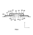
- FIG. 9 is a bottom cross-sectional view illustrating the front resonator of FIG. 4 ;
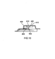
- FIG. 10 is a left side cross-sectional view illustrating the front resonator of FIG. 4 ;
- FIG. 11 is a horizontal cross-sectional view illustrating the front resonator of FIG. 4 mounted in the wireless device of FIG. 1 ;
- FIG. 12 is a partial cross-sectional perspective view illustrating the front resonator of FIG. 4 mounted in the wireless device of FIG. 1 ;
- FIG. 13 is a partial perspective view (outlet mesh and foam ring removed) illustrating the front resonator of FIG. 4 mounted in the wireless device of FIG. 1 ;
- FIG. 14 is a partial perspective view illustrating an outlet mesh and foam ring mounted over the front resonator of FIG. 4 mounted in the wireless device of FIG. 1 .
- FIG. 1 is a front view illustrating a wireless device 100 in accordance with an embodiment of the application.
- the wireless device 100 includes a cover or case 150, a display (e.g., a liquid crystal display (“LCD”)) 122, a graphical user interface ("GUI") 180 displayed on the display 122, a speaker 134, a keyboard (or keypad) 132, a thumbwheel (or trackwheel) 110, various select buttons 120 and various inputs/outputs (e.g., power connector jack, data interface ports, headphones jack, etc.) 160.
- the wireless device 100 typically includes one or more circuit boards (not shown in FIG.
- FIG. 2 is a block diagram illustrating the wireless device 100 of FIG. 1 .
- the wireless device 100 may operate over a wireless network 220.
- the wireless network 220 may include antenna, base stations, access points, transceivers, supporting radio equipment, etc., as known to those of ordinary skill in the art, for supporting wireless communications between the wireless device 100 and other devices (not shown).
- the wireless device 100 may be a two-way communication device having at least voice and advanced data communication capabilities, including the capability to communicate with other devices. Depending on the functionality provided by the device 100, it may be referred to as a data messaging device, a two-way pager, a cellular telephone with data messaging capabilities, a wireless Internet appliance, a data communication device (with or without telephony capabilities), a Wi-Fi device, a WLAN device, a dual-mode (i.e., Wi-Fi and cellular) device, or a portable audio device.
- the device 100 may communicate with any one of a plurality of transceiver stations (not shown) within its geographic coverage area.
- the wireless device 100 may have a communication subsystem 111, a subscriber identity module (or "SIM” card) 162 for inserting into a SIM interface (“IF") 164 in order to operate on a cellular network (e.g., a global system for mobile communication (“GSM”) network), a battery IF 154 for receiving one or more rechargeable batteries 156, a microprocessor 138 which controls overall operation of the device 100, a flash memory 124 or other persistent store, a random access memory (“RAM”) 126, auxiliary input/output (“I/O”) subsystems 128, a serial port (e.g., a universal serial bus (“USB”) port) 131, a microphone 136, a short-range communications subsystem 141 and other device subsystems 142.
- SIM subscriber identity module
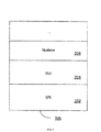
- FIG. 3 is a block diagram illustrating a memory 200 of the wireless device 100 of FIG. 1 .
- the microprocessor 138 is coupled to the memory 200.
- the memory 200 has various hardware and software components for storing information (e.g., instructions, data, database tables, test parameters, etc.) for enabling operation of the device 100 and may include flash memory 124, RAM 126, ROM (not shown), disk drives (not shown), etc.
- the memory 200 may include a variety of storage devices typically arranged in a hierarchy of storage as understood to those skilled in the art.
- operating system software modules 202 resident on the device 100 may provide a basic set of operations for supporting various applications typically operable through the GUI 180 and supporting GUI software modules 204.
- the wireless device 100 may be provided with additional hardware and/or software modules 206 for facilitating and implementing various functions.
- FIG. 4 is a front view illustrating a front resonator 400 for the wireless device 100 of FIG. 1 in accordance with an embodiment of the application.
- FIG. 5 is a back view illustrating the front resonator 400 of FIG. 4 .
- FIG. 6 is a bottom view illustrating the front resonator 400 of FIG. 4 .
- FIG. 7 is a left side view illustrating the front resonator 400 of FIG. 4 .
- FIG. 8 is a front cross-sectional perspective view illustrating the front resonator 400 of FIG. 4 .
- FIG. 9 is a bottom cross-sectional view illustrating the front resonator 400 of FIG. 4 .
- FIG. 10 is a left side cross-sectional view illustrating the front resonator 400 of FIG. 4 .
- the front resonator 400 includes a frame or enclosure 410 into which a panel or plate 420 is inserted.
- the enclosure 410, plate 420 and an upper surface 1100 of the speaker 134 form a front volume 900 for the speaker 134.
- the plate 420 has a groove, channel, or trough 800 formed in an upper surface 421 of the plate 420 such that when the plate 420 is inserted into the enclosure 410, a duct, conduit, or tube 910 is formed between an inner surface 411 of the enclosure 410 and the upper surface 421 of the plate 420.
- An opening 500 formed in the plate 420 proximate the center of the trough 800 couples the tube 910 to the front volume 900.
- sound generated by the speaker 134 travels through the front volume 900, through the central opening 500 in the plate 420 and into the tube 910, through the tube 910 and out through the openings 430, 440 in the enclosure 410 over each end 530, 540 of the trough 800.
- the tube 910 may be considered as including first and second sections (or tubes) 531, 541, each section (or tube) 531, 541 having a first end 530, 540 and an associated opening 430, 440 into the external environment and a second end 532, 542 having an opening 500 into the front volume 900.
- FIG. 11 is a horizontal cross-sectional view illustrating the front resonator 400 of FIG. 4 mounted in the wireless device 100 of FIG. 1 .
- FIG. 12 is a partial cross-sectional perspective view illustrating the front resonator 400 of FIG. 4 mounted in the wireless device 100 of FIG. 1 .
- FIG. 13 is a partial perspective view (outlet mesh 1110, dust net 1120 and foam ring 1130 removed) illustrating the front resonator 400 of FIG. 4 mounted in the wireless device 100 of FIG. 1 .
- FIG. 14 is a partial perspective view illustrating an outlet mesh 1110 and foam ring 1120 mounted over the front resonator 400 of FIG. 4 mounted in the wireless device 100 of FIG. 1 .
- a foam ring 1120, dust net 1120, and/or outlet mesh 1110 may be provided over the front resonator 400 when it is mounted in the wireless device 100 to protect the front resonator 400 and speaker 134.
- the speaker 134 is a dynamic speaker (e.g., a cone and magnet speaker).
- the front resonator 400 may be used in conjunction with a microphone or loud speaker.
- the edges of the enclosure 410 and plate 420 are rounded to reduce turbulence and to ease manufacturing tolerances.
- the enclosure 410 and plate 420 are made of metal and are welded or glued together.
- the enclosure 410 and plate 420 may be made of plastic.
- each section 531, 541 of the tube 910 is approximately 0.4 mm high, by 1.2 mm wide, by 2.5 mm long and the front volume 900 is approximately 40 mm 3 .
- the front resonator 400 may include two or more tubes 910.
- the tube 910 may be formed or mounted on an outer surface 412 of the frame or enclosure 410.
- a front resonator 400 for a speaker 134 of a wireless device 100 comprising: an enclosure 410 mounted over the speaker 134 and forming with an upper surface 1100 of the speaker 134 a front volume 900 for the front resonator 400; and, a horizontal (e.g., in the x - y plane) or approximately horizontal tube 910 formed or mounted on a surface (e.g., 411) of the enclosure 410, the tube 910 coupled (e.g., 500) to the front volume 900 and the tube 910 having at least one end 430, 440 to emit sound generated by the speaker 134 and passing through the front volume 900 and tube 910 from the wireless device 100.
- a horizontal e.g., in the x - y plane
- the tube 910 coupled (e.g., 500) to the front volume 900 and the tube 910 having at least one end 430, 440 to emit sound generated by the speaker 134 and passing through the front volume 900 and tube 910 from the wireless device 100.
- the tube 910 may be horizontal (e.g., in the x - y plane) or approximately horizontal with respect to a vertical axis (e.g., the z - axis) of the front volume 900.
- the tube 910 may be formed or mounted on an inner surface 411 of the enclosure 410.
- the tube 910 may be formed by a plate 420 having an upper surface 421 mounted to the inner surface 411 of the enclosure 410, the upper surface 421 of the plate 420 having a trough 800 formed therein, the trough 800 and the inner surface 411 of the enclosure 410 forming the tube 910, the trough 800 having an opening 500 formed therein to couple the front volume 900 to the tube 910, the enclosure 410 having at least one opening 430, 440 formed therein and aligned proximate at least one respective end 530, 540 of the trough 800 to emit sound generated by the speaker 134 and passing through the front volume 900 and tube 910 from the wireless device 100.
- the trough 800 may be straight.
- the opening 500 in the trough 800 may be formed proximate a center of the trough 800.
- the opening 500 in the trough 800 may be formed in a bottom of the trough 800.
- the trough 800 may have a smooth shape with rounded ends.
- the at least one opening 430, 440 in the enclosure 410 may have semicircular and rectangular portions aligning with at least one respective end 530, 540 of the trough 800.
- the opening 500 in the trough 800 may have a rectangular shape.
- the upper surface 421 of the plate 420, the inner surface 411 of the enclosure 410, the trough 800 and a mounting plane of the speaker 134 may be parallel or approximately parallel.
- a volume of the front volume 900 and a volume of the tube 910 may be selected to provide a frequency response of approximately 4 kHz.
- the tube 910 may have first and second sections 531, 541.
- each of the first and second sections 531, 541 may be approximately 0.4 mm high, by 1.2 mm wide, by 2.5 mm long and the front volume 900 may be approximately 40 mm 3 .
- the enclosure 410 may have a rounded, rectangular, open box-like shape.
- the inner surface 411 of the enclosure 410 may be an inner upper surface 411 of the enclosure 410.
- the plate 420 may be mounted in the enclosure 410 by welding or gluing.
- the enclosure 410 and the plate 420 may be formed from metal or plastic.
- the speaker 134 may be a cone and magnet speaker.
- the speaker 134 and front resonator 400 may be mounted within a case 150 of the wireless device 100.
- the tube 910 may be one or more tubes 910. And, the tube 910 may be formed or mounted on an outer surface 412 of the enclosure 410.
- a wireless device 100 having a front resonator 400 as described above.
- the axis of the tube 910, 531, 541 is arranged horizontally with respect to the front volume 900 rather than vertically.
- the overall height of the front resonator 400 is reduced and hence the overall thickness of the wireless device 100 may also be reduced.
- L new / L old V old / V new .
- V new 0.5 V old
- L new 2 L old .
- tube length must be doubled which is not generally implementable in the vertical direction in a wireless device.
- the tube 910, 531, 541 allows for a further reduction in the overall thickness of the wireless device 100.
- the tube 910, 531, 541 is physically protected from damage.
- the use of two sections or tubes 531, 541 allows placing tolerances during manufacturing to be less strict (e.g., if one section or tube 531 is a bit longer, the other section or tube 541 will be a bit shorter).
- selected rounding of the edges, corners and surfaces of the enclosure 410 and plate 420 reduce turbulences and eases manufacturing tolerances.
- the above embodiments may provide one or more of these advantages without significant adverse effect upon speaker performance.
Landscapes
- Health & Medical Sciences (AREA)
- Otolaryngology (AREA)
- Physics & Mathematics (AREA)
- Engineering & Computer Science (AREA)
- Acoustics & Sound (AREA)
- Signal Processing (AREA)
- Obtaining Desirable Characteristics In Audible-Bandwidth Transducers (AREA)
- Transceivers (AREA)
Abstract
Description
- This application relates to the field of wireless devices, and more specifically, to a front resonator for a speaker of a wireless device.
- Current wireless mobile communication devices include microprocessors, memory, soundcards, speakers, headphones and run one or more software applications in addition to providing for voice communications.
- Published
U.S. patent application serial no. 2007/147646 relates to an electro-acoustic apparatus having a housing with a housing wall and having an electro-acoustic transducer that is arranged facing the housing wall. A front chamber volume that forms an acoustic spring is provided between the transducer and the housing wall. In the housing wall a sound outlet aperture that preferably forms an acoustic mass is provided. Between the front chamber volume and the sound outlet aperture a sound guide channel is provided. - Published
EP 1916869 discloses a back resonator for a speaker of a wireless device where the back resonator consists in a twisted tube mounted onto the inner surface of the enclosure. - One problem with current wireless devices pertains to speaker performance. Speakers in wireless devices require a front resonator to perform properly. The front resonator typically consists of a tube coupled to a front volume which is located in front of the speaker. Sound generated by the speaker travels through the front volume, through the tube and into the air surrounding the wireless device where it is received by a user's ear. The tube and front volume are sized to obtain a desired frequency response. As such, to achieve a desired level of speaker performance, the size (e.g., length, volume, etc.) of the tube and/or front volume may have to be adjusted. However, an increase in the length of the tube, for example, will increase the thickness of the wireless device thus increasing the overall size of the wireless device, which is not desirable.
- A need therefore exists for an improved front resonator for a speaker of a wireless device. Accordingly, a solution that addresses, at least in part, the above and other shortcomings is desired.
- These needs and others are addressed by a resonator providing in accordance with
claim 1. Advantageous embodiments are provided in the dependent claims thereto. A wireless device in accordance with claim 15 is also provided. Features and advantages of the embodiments of the present application will become apparent from the following detailed description, taken in combination with the appended drawings, in which: -
FIG. 1 is a front view illustrating a wireless device in accordance with an embodiment of the application; -
FIG. 2 is a block diagram illustrating the wireless device ofFIG. 1 ; -
FIG. 3 is a block diagram illustrating a memory of the wireless device ofFIG. 1 ; -
FIG. 4 is a front view illustrating a front resonator for the wireless device ofFIG. 1 in accordance with an embodiment of the application; -
FIG. 5 is a back view illustrating the front resonator ofFIG. 4 ; -
FIG. 6 is a bottom view illustrating the front resonator ofFIG. 4 ; -
FIG. 7 is a left side view illustrating the front resonator ofFIG. 4 ; -
FIG. 8 is a front cross-sectional perspective view illustrating the front resonator ofFIG. 4 ; -
FIG. 9 is a bottom cross-sectional view illustrating the front resonator ofFIG. 4 ; -
FIG. 10 is a left side cross-sectional view illustrating the front resonator ofFIG. 4 ; -
FIG. 11 is a horizontal cross-sectional view illustrating the front resonator ofFIG. 4 mounted in the wireless device ofFIG. 1 ; -
FIG. 12 is a partial cross-sectional perspective view illustrating the front resonator ofFIG. 4 mounted in the wireless device ofFIG. 1 ; -
FIG. 13 is a partial perspective view (outlet mesh and foam ring removed) illustrating the front resonator ofFIG. 4 mounted in the wireless device ofFIG. 1 ; and -
FIG. 14 is a partial perspective view illustrating an outlet mesh and foam ring mounted over the front resonator ofFIG. 4 mounted in the wireless device ofFIG. 1 . - It will be noted that throughout the appended drawings, like features are identified by like reference numerals.
- In the following description, details are set forth to provide an understanding of the application. In some instances, certain software, circuits, structures and techniques have not been described or shown in detail in order not to obscure the application.
-
FIG. 1 is a front view illustrating awireless device 100 in accordance with an embodiment of the application. Thewireless device 100 includes a cover orcase 150, a display (e.g., a liquid crystal display ("LCD")) 122, a graphical user interface ("GUI") 180 displayed on thedisplay 122, aspeaker 134, a keyboard (or keypad) 132, a thumbwheel (or trackwheel) 110, variousselect buttons 120 and various inputs/outputs (e.g., power connector jack, data interface ports, headphones jack, etc.) 160. Internally, thewireless device 100 typically includes one or more circuit boards (not shown inFIG. 1 ), aCPU 138,memory battery 156, an antenna (not shown inFIG. 1 ), etc., which are operatively coupled to the various inputs/outputs 160, thekeyboard 132, thedisplay 122, thespeaker 134, etc., as will be described below. Further details pertaining to thespeaker 134, such as a resonator associated with thespeaker 134, will also be described below. -
FIG. 2 is a block diagram illustrating thewireless device 100 ofFIG. 1 . Thewireless device 100 may operate over awireless network 220. Thewireless network 220 may include antenna, base stations, access points, transceivers, supporting radio equipment, etc., as known to those of ordinary skill in the art, for supporting wireless communications between thewireless device 100 and other devices (not shown). - The
wireless device 100 may be a two-way communication device having at least voice and advanced data communication capabilities, including the capability to communicate with other devices. Depending on the functionality provided by thedevice 100, it may be referred to as a data messaging device, a two-way pager, a cellular telephone with data messaging capabilities, a wireless Internet appliance, a data communication device (with or without telephony capabilities), a Wi-Fi device, a WLAN device, a dual-mode (i.e., Wi-Fi and cellular) device, or a portable audio device. Thedevice 100 may communicate with any one of a plurality of transceiver stations (not shown) within its geographic coverage area. - The
wireless device 100 may have acommunication subsystem 111, a subscriber identity module (or "SIM" card) 162 for inserting into a SIM interface ("IF") 164 in order to operate on a cellular network (e.g., a global system for mobile communication ("GSM") network), abattery IF 154 for receiving one or morerechargeable batteries 156, amicroprocessor 138 which controls overall operation of thedevice 100, aflash memory 124 or other persistent store, a random access memory ("RAM") 126, auxiliary input/output ("I/O")subsystems 128, a serial port (e.g., a universal serial bus ("USB") port) 131, amicrophone 136, a short-range communications subsystem 141 andother device subsystems 142. -
FIG. 3 is a block diagram illustrating amemory 200 of thewireless device 100 ofFIG. 1 . Themicroprocessor 138 is coupled to thememory 200. Thememory 200 has various hardware and software components for storing information (e.g., instructions, data, database tables, test parameters, etc.) for enabling operation of thedevice 100 and may includeflash memory 124, RAM 126, ROM (not shown), disk drives (not shown), etc. In general, thememory 200 may include a variety of storage devices typically arranged in a hierarchy of storage as understood to those skilled in the art. To provide a user-friendly environment to control the operation of thedevice 100, operating system ("O/S")software modules 202 resident on thedevice 100 may provide a basic set of operations for supporting various applications typically operable through theGUI 180 and supportingGUI software modules 204. Thewireless device 100 may be provided with additional hardware and/orsoftware modules 206 for facilitating and implementing various functions. -
FIG. 4 is a front view illustrating afront resonator 400 for thewireless device 100 ofFIG. 1 in accordance with an embodiment of the application.FIG. 5 is a back view illustrating thefront resonator 400 ofFIG. 4 .FIG. 6 is a bottom view illustrating thefront resonator 400 ofFIG. 4 .FIG. 7 is a left side view illustrating thefront resonator 400 ofFIG. 4 .FIG. 8 is a front cross-sectional perspective view illustrating thefront resonator 400 ofFIG. 4 .FIG. 9 is a bottom cross-sectional view illustrating thefront resonator 400 ofFIG. 4 . And,FIG. 10 is a left side cross-sectional view illustrating thefront resonator 400 ofFIG. 4 . - According to one embodiment, the
front resonator 400 includes a frame orenclosure 410 into which a panel orplate 420 is inserted. Theenclosure 410,plate 420 and anupper surface 1100 of thespeaker 134 form afront volume 900 for thespeaker 134. Theplate 420 has a groove, channel, ortrough 800 formed in anupper surface 421 of theplate 420 such that when theplate 420 is inserted into theenclosure 410, a duct, conduit, ortube 910 is formed between aninner surface 411 of theenclosure 410 and theupper surface 421 of theplate 420. Anopening 500 formed in theplate 420 proximate the center of thetrough 800 couples thetube 910 to thefront volume 900.Openings enclosure 410 aligned over respective ends 530, 540 of thetrough 800 couple thetube 910 to the external environment. In operation, sound generated by thespeaker 134 travels through thefront volume 900, through thecentral opening 500 in theplate 420 and into thetube 910, through thetube 910 and out through theopenings enclosure 410 over eachend trough 800. - The
tube 910 may be considered as including first and second sections (or tubes) 531, 541, each section (or tube) 531, 541 having afirst end opening second end opening 500 into thefront volume 900. -
FIG. 11 is a horizontal cross-sectional view illustrating thefront resonator 400 ofFIG. 4 mounted in thewireless device 100 ofFIG. 1 .FIG. 12 is a partial cross-sectional perspective view illustrating thefront resonator 400 ofFIG. 4 mounted in thewireless device 100 ofFIG. 1 .FIG. 13 is a partial perspective view (outlet mesh 1110,dust net 1120 andfoam ring 1130 removed) illustrating thefront resonator 400 ofFIG. 4 mounted in thewireless device 100 ofFIG. 1 . And,FIG. 14 is a partial perspective view illustrating anoutlet mesh 1110 andfoam ring 1120 mounted over thefront resonator 400 ofFIG. 4 mounted in thewireless device 100 ofFIG. 1 . - According to one embodiment, a
foam ring 1120,dust net 1120, and/oroutlet mesh 1110 may be provided over thefront resonator 400 when it is mounted in thewireless device 100 to protect thefront resonator 400 andspeaker 134. According to one embodiment, thespeaker 134 is a dynamic speaker (e.g., a cone and magnet speaker). According to one embodiment, thefront resonator 400 may be used in conjunction with a microphone or loud speaker. According to one embodiment, the edges of theenclosure 410 andplate 420 are rounded to reduce turbulence and to ease manufacturing tolerances. According to one embodiment, theenclosure 410 andplate 420 are made of metal and are welded or glued together. According to another embodiment, theenclosure 410 andplate 420 may be made of plastic. According to one embodiment, for a frequency response of approximately 4 kHz, eachsection tube 910 is approximately 0.4 mm high, by 1.2 mm wide, by 2.5 mm long and thefront volume 900 is approximately 40 mm3. According to one embodiment, thefront resonator 400 may include two ormore tubes 910. According to one embodiment, thetube 910 may be formed or mounted on anouter surface 412 of the frame orenclosure 410. - Thus, according to one embodiment, there is provided a
front resonator 400 for aspeaker 134 of awireless device 100, comprising: anenclosure 410 mounted over thespeaker 134 and forming with anupper surface 1100 of the speaker 134 afront volume 900 for thefront resonator 400; and, a horizontal (e.g., in the x - y plane) or approximatelyhorizontal tube 910 formed or mounted on a surface (e.g., 411) of theenclosure 410, thetube 910 coupled (e.g., 500) to thefront volume 900 and thetube 910 having at least oneend speaker 134 and passing through thefront volume 900 andtube 910 from thewireless device 100. - The
tube 910 may be horizontal (e.g., in the x - y plane) or approximately horizontal with respect to a vertical axis (e.g., the z - axis) of thefront volume 900. Thetube 910 may be formed or mounted on aninner surface 411 of theenclosure 410. Thetube 910 may be formed by aplate 420 having anupper surface 421 mounted to theinner surface 411 of theenclosure 410, theupper surface 421 of theplate 420 having atrough 800 formed therein, thetrough 800 and theinner surface 411 of theenclosure 410 forming thetube 910, thetrough 800 having anopening 500 formed therein to couple thefront volume 900 to thetube 910, theenclosure 410 having at least oneopening respective end trough 800 to emit sound generated by thespeaker 134 and passing through thefront volume 900 andtube 910 from thewireless device 100. Thetrough 800 may be straight. Theopening 500 in thetrough 800 may be formed proximate a center of thetrough 800. Theopening 500 in thetrough 800 may be formed in a bottom of thetrough 800. Thetrough 800 may have a smooth shape with rounded ends. The at least oneopening enclosure 410 may have semicircular and rectangular portions aligning with at least onerespective end trough 800. Theopening 500 in thetrough 800 may have a rectangular shape. Theupper surface 421 of theplate 420, theinner surface 411 of theenclosure 410, thetrough 800 and a mounting plane of thespeaker 134 may be parallel or approximately parallel. A volume of thefront volume 900 and a volume of thetube 910 may be selected to provide a frequency response of approximately 4 kHz. Thetube 910 may have first andsecond sections second sections front volume 900 may be approximately 40 mm3. Theenclosure 410 may have a rounded, rectangular, open box-like shape. Theinner surface 411 of theenclosure 410 may be an innerupper surface 411 of theenclosure 410. Theplate 420 may be mounted in theenclosure 410 by welding or gluing. Theenclosure 410 and theplate 420 may be formed from metal or plastic. Thespeaker 134 may be a cone and magnet speaker. Thespeaker 134 andfront resonator 400 may be mounted within acase 150 of thewireless device 100. Thetube 910 may be one ormore tubes 910. And, thetube 910 may be formed or mounted on anouter surface 412 of theenclosure 410. - According to another embodiment, there is provided a
wireless device 100 having afront resonator 400 as described above. - The above embodiments may contribute to an improved speaker system and may provide one or more advantages. First, the axis of the
tube front volume 900 rather than vertically. As such, the overall height of thefront resonator 400 is reduced and hence the overall thickness of thewireless device 100 may also be reduced. For example, if L = tube length and V = front volume, then Lnew / Lold = Vold / Vnew. As such, if Vnew = 0.5 Vold, then Lnew = 2 Lold. In other words, if the front volume is halved, tube length must be doubled which is not generally implementable in the vertical direction in a wireless device. Second, including thetube front volume 900 rather than external to thefront volume 900, according to one embodiment, allows for a further reduction in the overall thickness of thewireless device 100. Third, being contained within theenclosure 410, according to one embodiment, thetube tubes tube 531 is a bit longer, the other section ortube 541 will be a bit shorter). Fifth, selected rounding of the edges, corners and surfaces of theenclosure 410 andplate 420 reduce turbulences and eases manufacturing tolerances. Sixth, the above embodiments may provide one or more of these advantages without significant adverse effect upon speaker performance. - The embodiments of the application described above are intended to be exemplary only. Those skilled in this art will understand that various modifications of detail may be made to these embodiments, all of which come within the scope of the application.
- Furthermore, one or more of the following numbered clauses may describe and relate to further aspects or features within the context of the present teaching:
- 1. A front resonator (400) for a speaker (134) of a wireless device (100), comprising:
- an enclosure (410) mounted over the speaker (134) and forming with an upper surface (1100) of the speaker (134) a front volume (900) for the front resonator (400); and,
- a horizontal or approximately horizontal tube (910) formed or mounted on a surface (411) of the enclosure (410), the tube (910) coupled to the front volume (900), and the tube (910) having at least one end (430, 440) to emit sound generated by the speaker (134) and passing through the front volume (900) and tube (910) from the wireless device (100).
- 2. The front resonator (400) of
clause 1 wherein the tube (910) is horizontal or approximately horizontal with respect to a vertical axis of the front volume (900). - 3. The front resonator (400) of
clauses 1 or 2 wherein the tube (910) is formed or mounted on an inner surface (411) of the enclosure (410). - 4. The front resonator (400) of clause 3 wherein the tube (910) is formed by a plate (420) having an upper surface (421) mounted to the inner surface (411) of the enclosure (410), the upper surface (421) of the plate (420) having a trough (800) formed therein, the trough (800) and the inner surface (411) of the enclosure (410) forming the tube (910), the trough (800) having an opening (500) formed therein to couple the front volume (900) to the tube (910), the enclosure (410) having at least one opening (430, 440) formed therein and aligned proximate at least one respective end (530, 540) of the trough (800) to emit sound generated by the speaker (134) and passing through the front volume (900) and tube (910) from the wireless device (100).
- 5. The front resonator (400) of clause 4 wherein the trough (800) is straight.
- 6. The front resonator (400) of clauses 4 or 5 wherein the opening (500) in the trough (800) is formed proximate a center of the trough (800).
- 7. The front resonator (400) of any one of clauses 4 to 6 wherein the opening (500) in the trough (800) is formed in a bottom of the trough (800).
- 8. The front resonator (400) of any one of clauses 4 to 7 wherein the trough (800) has a smooth shape with rounded ends.
- 9. The front resonator (400) of clause 8 wherein the at least one opening (430, 440) in the enclosure (410) has semicircular and rectangular portions aligning with at least one respective end (530, 540) of the trough (800).
- 10. The front resonator (400) of any one of clauses 4 to 9 wherein the opening (500) in the trough (800) has a rectangular shape.
- 11. The front resonator (400) of any one of clauses 4 to 10 wherein the upper surface of the plate (420), the inner surface (411) of the enclosure (410), the trough (800), and a mounting plane of the speaker (134) are parallel or approximately parallel.
- 12. The front resonator (400) of any one of
clauses 1 to 11 wherein a volume of the front volume (900) and a volume of the tube (910) are selected to provide a frequency response of approximately 4 kHz. - 13. The front resonator (400) of any one of
clauses 1 to 12 wherein the tube (910) has first and second sections (531, 541). - 14. The front resonator (400) of clause 13 wherein, for a frequency response of approximately 4 kHz, each of the first and second sections (531, 541) is approximately 0.4 mm high, by 1.2 mm wide, by 2.5 mm long and the front volume (900) is approximately 40 mm3.
- 15. A wireless device (100) having a front resonator (400) according to any one of
clauses 1 to 14.
Claims (15)
- A front resonator (400) for mounting over a speaker (134) in a wireless device (100), comprising:an enclosure (410) mounted over the speaker (134) and forming with an upper surface (1100) of the speaker (134) a front volume (900) for the front resonator (400); anda plate (420) having an upper surface (421) mounted to an inner surface (411) of the enclosure (410), the upper surface (421) of the plate (420) having a trough (800) with an opening (500) formed therein,wherein
the trough (800) and the inner surface (411) of the enclosure (410) form a tube (910) having at least one end (430, 440) to emit sound generated by the speaker (134) through the front volume (900) and tube (910) from the wireless device (100). - The front resonator (400) of claim 1, wherein:the trough (800) has an opening (500) formed therein to couple the front volume (900) to the tube (910).
- The front resonator (400) of claim 2, wherein the opening (500) in the trough (800) is formed proximate a center of the trough (800).
- The front resonator (400) of claim 2 or claim 3, wherein the opening (500) in the trough (800) is formed in a bottom of the trough (800).
- The front resonator (400) of any one of claims 2 to 4, wherein the opening (500) in the trough (800) has a rectangular shape.
- The front resonator (400) of any preceding claim, wherein:the least one opening (430, 440) is aligned proximate at least one respective end (530, 540) of the trough (800).
- The front resonator (400) of any preceding claim, wherein the tube (910) is horizontal or approximately horizontal with respect to a vertical axis of the front volume (900).
- The front resonator (400) of any preceding claim, wherein the trough (800) is straight.
- The front resonator (400) of any preceding claim, wherein the trough (800) has a smooth shape with rounded ends.
- The front resonator (400) of claim 9, wherein the at least one opening (430, 440) has semicircular and rectangular portions aligning with at least one respective end (530, 540) of the trough (800).
- The front resonator (400) of any preceding claim, wherein the upper surface of the plate (420), the inner surface (411) of the enclosure (410), the trough (800) and a mounting plane of the speaker (134) are parallel or approximately parallel.
- The front resonator (400) of any preceding claim, wherein a volume of the front volume (900) and a volume of the tube (910) are selected to provide a frequency response of approximately 4 kHz.
- The front resonator (400) of any preceding claim, wherein the tube (910) has first and second sections (531, 541).
- The front resonator (400) of claim 13, wherein for a frequency response of approximately 4 kHz, each of the first and second sections (531, 541) is approximately 0.4 mm high, by 1.2 mm wide, by 2.5 mm long and the front volume (900) is approximately 40 mm3.
- A wireless device (100) having a front resonator (400) according to any one of claims 1 to 14.
Priority Applications (1)
| Application Number | Priority Date | Filing Date | Title |
|---|---|---|---|
| EP13154777.0A EP2595409A3 (en) | 2009-08-20 | 2009-08-20 | A front resonator for a speaker of a wireless device |
Applications Claiming Priority (2)
| Application Number | Priority Date | Filing Date | Title |
|---|---|---|---|
| EP09168256.7A EP2288177B1 (en) | 2009-08-20 | 2009-08-20 | A front resonator for a speaker of a wireless device |
| EP13154777.0A EP2595409A3 (en) | 2009-08-20 | 2009-08-20 | A front resonator for a speaker of a wireless device |
Related Parent Applications (1)
| Application Number | Title | Priority Date | Filing Date |
|---|---|---|---|
| EP09168256.7 Division | 2009-08-20 |
Publications (2)
| Publication Number | Publication Date |
|---|---|
| EP2595409A2 true EP2595409A2 (en) | 2013-05-22 |
| EP2595409A3 EP2595409A3 (en) | 2013-08-07 |
Family
ID=41719371
Family Applications (2)
| Application Number | Title | Priority Date | Filing Date |
|---|---|---|---|
| EP13154777.0A Ceased EP2595409A3 (en) | 2009-08-20 | 2009-08-20 | A front resonator for a speaker of a wireless device |
| EP09168256.7A Active EP2288177B1 (en) | 2009-08-20 | 2009-08-20 | A front resonator for a speaker of a wireless device |
Family Applications After (1)
| Application Number | Title | Priority Date | Filing Date |
|---|---|---|---|
| EP09168256.7A Active EP2288177B1 (en) | 2009-08-20 | 2009-08-20 | A front resonator for a speaker of a wireless device |
Country Status (2)
| Country | Link |
|---|---|
| EP (2) | EP2595409A3 (en) |
| CA (1) | CA2711351C (en) |
Citations (2)
| Publication number | Priority date | Publication date | Assignee | Title |
|---|---|---|---|---|
| US20070147646A1 (en) | 2003-11-25 | 2007-06-28 | Koninklijke Philips Electronics N.V. | Electro-acoustic apparatus comprising an electro-acoustic transducer |
| EP1916869A2 (en) | 2006-10-25 | 2008-04-30 | LG Electronics Inc. | Speaker mounted in an enclosure for a mobile communication device |
Family Cites Families (8)
| Publication number | Priority date | Publication date | Assignee | Title |
|---|---|---|---|---|
| DK173789B1 (en) * | 1998-10-05 | 2001-10-22 | Kirk Acoustics As | Electroacoustic communication device |
| US6339649B1 (en) * | 1999-04-12 | 2002-01-15 | Waterson Chen | Loudspeaker system with stackable loudspeaker units |
| US7068979B2 (en) * | 2001-11-27 | 2006-06-27 | Nokia Corporation | Mobile telecommunications device |
| US7058366B2 (en) * | 2002-12-09 | 2006-06-06 | Sony Ericsson Mobile Communications Ab | Wireless terminal providing sound pressure level dissipation through channeled porting of sound |
| US6785395B1 (en) * | 2003-06-02 | 2004-08-31 | Motorola, Inc. | Speaker configuration for a portable electronic device |
| JP4230847B2 (en) * | 2003-07-11 | 2009-02-25 | 株式会社東芝 | Mobile terminal device |
| JP2006279260A (en) * | 2005-03-28 | 2006-10-12 | Nec Saitama Ltd | Portable terminal |
| US8180075B2 (en) * | 2007-04-26 | 2012-05-15 | Motorola Mobility, Inc. | Arrangement for variable bass reflex cavities |
-
2009
- 2009-08-20 EP EP13154777.0A patent/EP2595409A3/en not_active Ceased
- 2009-08-20 EP EP09168256.7A patent/EP2288177B1/en active Active
-
2010
- 2010-07-26 CA CA2711351A patent/CA2711351C/en active Active
Patent Citations (2)
| Publication number | Priority date | Publication date | Assignee | Title |
|---|---|---|---|---|
| US20070147646A1 (en) | 2003-11-25 | 2007-06-28 | Koninklijke Philips Electronics N.V. | Electro-acoustic apparatus comprising an electro-acoustic transducer |
| EP1916869A2 (en) | 2006-10-25 | 2008-04-30 | LG Electronics Inc. | Speaker mounted in an enclosure for a mobile communication device |
Also Published As
| Publication number | Publication date |
|---|---|
| EP2288177A1 (en) | 2011-02-23 |
| EP2288177B1 (en) | 2013-07-31 |
| EP2595409A3 (en) | 2013-08-07 |
| CA2711351A1 (en) | 2011-02-20 |
| CA2711351C (en) | 2014-10-21 |
Similar Documents
| Publication | Publication Date | Title |
|---|---|---|
| US10085086B2 (en) | Resonance damping for audio transducer systems | |
| US8483422B2 (en) | Enclosure for a speaker of a wireless device | |
| US10027784B2 (en) | Speaker back cavity | |
| CN104685902B (en) | Acoustic back cavity system for sound transducer | |
| US8459403B2 (en) | Front resonator for a speaker of a wireless device | |
| CN101222784B (en) | Loudspeaker box structure and mobile electronic equipments adopting the same | |
| US7668320B2 (en) | Sound reproduction in portable electronic equipment | |
| CN207835746U (en) | Earphone loudspeaker box integration device | |
| CN101212838B (en) | Sound box structure and mobile electronic device employing the sound box structure | |
| EP2288177B1 (en) | A front resonator for a speaker of a wireless device | |
| CN111343552B (en) | Receiver and terminal | |
| CN221177908U (en) | Electronic equipment | |
| CN207766510U (en) | Wide sound field strip sound equipment | |
| EP2375705B1 (en) | Enclosure for a speaker of a wireless device | |
| CN101442694A (en) | Loudspeaker assembly | |
| CN210609626U (en) | Bass earphone | |
| CN115643333A (en) | Loudspeaker assembly and mobile terminal | |
| CN222235209U (en) | Housing and electronic device | |
| CN223912576U (en) | Shell of electronic equipment and electronic equipment | |
| CN201893916U (en) | Loudspeaker device |
Legal Events
| Date | Code | Title | Description |
|---|---|---|---|
| PUAI | Public reference made under article 153(3) epc to a published international application that has entered the european phase |
Free format text: ORIGINAL CODE: 0009012 |
|
| 17P | Request for examination filed |
Effective date: 20130211 |
|
| AC | Divisional application: reference to earlier application |
Ref document number: 2288177 Country of ref document: EP Kind code of ref document: P |
|
| AK | Designated contracting states |
Kind code of ref document: A2 Designated state(s): AT BE BG CH CY CZ DE DK EE ES FI FR GB GR HR HU IE IS IT LI LT LU LV MC MK MT NL NO PL PT RO SE SI SK SM TR |
|
| PUAL | Search report despatched |
Free format text: ORIGINAL CODE: 0009013 |
|
| AK | Designated contracting states |
Kind code of ref document: A3 Designated state(s): AT BE BG CH CY CZ DE DK EE ES FI FR GB GR HR HU IE IS IT LI LT LU LV MC MK MT NL NO PL PT RO SE SI SK SM TR |
|
| RIC1 | Information provided on ipc code assigned before grant |
Ipc: H04R 1/28 20060101AFI20130701BHEP |
|
| RAP1 | Party data changed (applicant data changed or rights of an application transferred) |
Owner name: BLACKBERRY LIMITED |
|
| RAP1 | Party data changed (applicant data changed or rights of an application transferred) |
Owner name: BLACKBERRY LIMITED |
|
| 17Q | First examination report despatched |
Effective date: 20150825 |
|
| STAA | Information on the status of an ep patent application or granted ep patent |
Free format text: STATUS: THE APPLICATION HAS BEEN REFUSED |
|
| 18R | Application refused |
Effective date: 20180303 |