EP2594977A1 - Zoom illuminating system and imaging apparatus employing the same - Google Patents
Zoom illuminating system and imaging apparatus employing the same Download PDFInfo
- Publication number
- EP2594977A1 EP2594977A1 EP12193481.4A EP12193481A EP2594977A1 EP 2594977 A1 EP2594977 A1 EP 2594977A1 EP 12193481 A EP12193481 A EP 12193481A EP 2594977 A1 EP2594977 A1 EP 2594977A1
- Authority
- EP
- European Patent Office
- Prior art keywords
- lens
- zoom
- illuminating system
- light source
- distance
- Prior art date
- Legal status (The legal status is an assumption and is not a legal conclusion. Google has not performed a legal analysis and makes no representation as to the accuracy of the status listed.)
- Granted
Links
Images


Classifications
-
- G—PHYSICS
- G02—OPTICS
- G02B—OPTICAL ELEMENTS, SYSTEMS OR APPARATUS
- G02B15/00—Optical objectives with means for varying the magnification
- G02B15/14—Optical objectives with means for varying the magnification by axial movement of one or more lenses or groups of lenses relative to the image plane for continuously varying the equivalent focal length of the objective
-
- G—PHYSICS
- G02—OPTICS
- G02B—OPTICAL ELEMENTS, SYSTEMS OR APPARATUS
- G02B15/00—Optical objectives with means for varying the magnification
- G02B15/14—Optical objectives with means for varying the magnification by axial movement of one or more lenses or groups of lenses relative to the image plane for continuously varying the equivalent focal length of the objective
- G02B15/142—Optical objectives with means for varying the magnification by axial movement of one or more lenses or groups of lenses relative to the image plane for continuously varying the equivalent focal length of the objective having two groups only
- G02B15/1421—Optical objectives with means for varying the magnification by axial movement of one or more lenses or groups of lenses relative to the image plane for continuously varying the equivalent focal length of the objective having two groups only the first group being positive
-
- G—PHYSICS
- G02—OPTICS
- G02B—OPTICAL ELEMENTS, SYSTEMS OR APPARATUS
- G02B15/00—Optical objectives with means for varying the magnification
- G02B15/14—Optical objectives with means for varying the magnification by axial movement of one or more lenses or groups of lenses relative to the image plane for continuously varying the equivalent focal length of the objective
- G02B15/142—Optical objectives with means for varying the magnification by axial movement of one or more lenses or groups of lenses relative to the image plane for continuously varying the equivalent focal length of the objective having two groups only
- G02B15/1425—Optical objectives with means for varying the magnification by axial movement of one or more lenses or groups of lenses relative to the image plane for continuously varying the equivalent focal length of the objective having two groups only the first group being negative
-
- G—PHYSICS
- G02—OPTICS
- G02B—OPTICAL ELEMENTS, SYSTEMS OR APPARATUS
- G02B19/00—Condensers, e.g. light collectors or similar non-imaging optics
-
- G—PHYSICS
- G02—OPTICS
- G02B—OPTICAL ELEMENTS, SYSTEMS OR APPARATUS
- G02B19/00—Condensers, e.g. light collectors or similar non-imaging optics
- G02B19/0004—Condensers, e.g. light collectors or similar non-imaging optics characterised by the optical means employed
- G02B19/0009—Condensers, e.g. light collectors or similar non-imaging optics characterised by the optical means employed having refractive surfaces only
- G02B19/0014—Condensers, e.g. light collectors or similar non-imaging optics characterised by the optical means employed having refractive surfaces only at least one surface having optical power
-
- G—PHYSICS
- G02—OPTICS
- G02B—OPTICAL ELEMENTS, SYSTEMS OR APPARATUS
- G02B19/00—Condensers, e.g. light collectors or similar non-imaging optics
- G02B19/0033—Condensers, e.g. light collectors or similar non-imaging optics characterised by the use
- G02B19/0047—Condensers, e.g. light collectors or similar non-imaging optics characterised by the use for use with a light source
- G02B19/0061—Condensers, e.g. light collectors or similar non-imaging optics characterised by the use for use with a light source the light source comprising a LED
-
- G—PHYSICS
- G02—OPTICS
- G02B—OPTICAL ELEMENTS, SYSTEMS OR APPARATUS
- G02B19/00—Condensers, e.g. light collectors or similar non-imaging optics
- G02B19/0033—Condensers, e.g. light collectors or similar non-imaging optics characterised by the use
- G02B19/009—Condensers, e.g. light collectors or similar non-imaging optics characterised by the use for use with infrared radiation
-
- H—ELECTRICITY
- H04—ELECTRIC COMMUNICATION TECHNIQUE
- H04N—PICTORIAL COMMUNICATION, e.g. TELEVISION
- H04N23/00—Cameras or camera modules comprising electronic image sensors; Control thereof
- H04N23/60—Control of cameras or camera modules
- H04N23/69—Control of means for changing angle of the field of view, e.g. optical zoom objectives or electronic zooming
Definitions
- the present invention relates to a zoom illuminating system capable of adjusting illumination according to imaging conditions, and an imaging apparatus employing the same.
- CCTV closed circuit television
- a fixed focus lens having a fixed focal length or a zoom lens having a zoom function is used as an imaging lens of a monitoring camera, and infrared illumination for night photographing is also used in a monitoring camera.
- the fixed focus lens is a wide-angle lens having a large diameter in order to monitor a dark place with a wide range.
- an illumination unit having a fixed illumination range is generally employed, and the illumination unit includes a plurality of light sources to illuminate a subject at night.
- the monitoring camera using the zoom lens require illumination covering a wide photographing range from a wide angle position to a telephoto position of the zoom lens. If an illumination unit having a fixed illumination range is used, light illumination efficiency is low since illumination aside a photographing range is not used. For example, light illustrated in a wide view angle at a telephoto position where only illumination in a narrow view angle is required is lost. Alternatively, a light source having a wide illumination range and a light source having a narrow illumination range may be used together to cover a wide photographing range from a wide angle position to a telephoto position.
- the present invention provides a zoom illumination system having an adjustable illumination range, and an imaging apparatus including the same.
- a zoom illuminating system having an adjustable illumination range and including: a light source; and a lens unit including at least one lens, wherein a distance from the light source to the at least one lens is variable.
- the light source may include at least one light emitting device emitting light in an infrared band.
- the lens unit may include a positive lens, wherein a distance from the light source to the positive lens may be variable.
- the lens unit may include: a first lens; and a second lens disposed between the first lens and the light source, wherein the illumination range may be adjusted by adjusting a distance between the first and second lenses.
- the first lens may be fixed and the second lens may be moved to adjust the distance between the first and second lenses.
- the first lens may be fixed and the light source may move together with the second lens.
- At least one of the first and second lenses may be a positive lens.
- the lens unit may include at least one aspherical surface.
- the second lens may be a spherical lens.
- an imaging apparatus including: the zoom illuminating system; a zoom lens system including a plurality of lens groups and zooming an image of an object as a distance between the plurality of lens groups varies; an image pickup device changing an optical image formed by the zoom lens system to an electric signal; and a control unit controlling zooming of the zoom lens system to be interlocked with adjusting of an illumination range of the zoom illuminating system.
- Magnification of the zoom lens system may be equal to or higher than 2.
- FIG. 1 is a block diagram schematically illustrating an imaging apparatus 1000 according to an embodiment of the present invention.
- the zoom illuminating system 100 includes a light source 110 and a lens unit 120 including at least one lens.
- a distance from the light source 110 to the at least one lens is variable so as to adjust an illumination range of light emitted from the light source 110.
- a light emitting device emitting light in an infrared band such as a light emitting diode (LED) or laser diode (LD) emitting light in a wavelength band of about 830 to 960 nm, may be employed as the light source 110.
- One or more light sources 110 may be used.
- An angle of beam spread of a light emitting device employed as the light source 110 is generally at least about 80°, and the lens unit 120 includes at least one positive lens so as to realize an illumination range in a view angle narrower than the angle of beam spread from such a light source 110.
- the illumination range of light emitted from the light source 110 varies according to photographing conditions, and for example, the lens unit 120 may be driven such that the illumination range of a short distance having a wide angle of beam spread is formed according to the wide angle position photographing conditions, and the illumination range of a long distance having a narrow angle of beam spread is formed according to the telephoto position photographing conditions.
- the imaging unit 300 includes the zoom lens system 320 and an image pickup device 340.
- the zoom lens system 320 includes a plurality of lens groups, and an image of an object may be zoomed as a distance between the lens groups varies. A number of lens groups forming the zoom lens system 320, or a type or number of lenses forming each lens group may be variously selected considering the optical performances such as magnification and aberration.
- the zoom lens system 320 may have at least 2X zoom magnification.
- the image pickup device 340 converts an optical image formed by the zoom lens system 320 to an electric signal, and may be a charged coupled device (CCD) or a complementary metal-oxide semiconductor (CMOS).
- CCD charged coupled device
- CMOS complementary metal-oxide semiconductor
- the control unit 200 controls zooming of the zoom lens system 320 and adjusting of an illumination range of the zoom lens system 320 to be interlocked with each other.
- the control unit 200 adjusts zoom magnifications, i.e., drives the zoom lens system 100 according to a command of a user, and drives the zoom illuminating system 100 to form a corresponding illumination range.
- the zoom lens system 320 is driven to have an illumination range having a wide angle of beam spread when the zoom lens system 320 is driven to have an optical arrangement corresponding to the wide angle position, and to have an illumination range having a narrow angle of beam spread when the zoom lens system 320 is driven to have an optical arrangement corresponding to the telephoto position.
- An angle of beam spread of light is widened at the wide angle position to increase an illumination area, and thus, illumination uniformity is obtained.
- An angle of beam spread of light is narrowed at the telephoto position so as to concentrate the light in a narrow area, and thus, illumination is increased.
- the imaging apparatus 1000 may include an increased number of light sources 110 or a plurality of zoom illuminating systems 100.
- a definition of an aspherical surface in the embodiments is as follows.
- x c ⁇ y 2 1 + 1 - K + 1 c ⁇ 2 y 2 + A y 4 + B y 6 + C y 8 + D y 10
- x denotes a distance from a vertex of a lens in an optical axis direction
- y denotes a distance in a direction perpendicular to an optical axis
- K denotes a conic constant
- A, B, C, and D denote aspherical surface coefficients
- c' denotes an inverse number (1/R) of a radius of curvature at the vertex of lens.
- D2 denotes a variable distance between lenses
- Asphere denotes an aspherical surface
- sphere denotes a spherical surface
- a unit of radius of curvature, thickness or distance, effective diameter, and focal length is mm.
- a refractive index relates to light in a wavelength band of e-ray.
- FIG. 2 shows views of optical arrangements of the zoom illuminating system 100 employed in the imaging apparatus 1000 of FIG. 1 , according to an embodiment of the present invention, the optical arrangements respectively corresponding to a wide angle position and telephoto position of the zoom lens system 320 of the imaging apparatus 1000.
- the zoom illuminating system 100 includes a first lens 121, a second lens 122, and the light source 110, wherein the second lens 122 is disposed between the first lens 121 and the light source 110.
- At least any one of the first and second lenses 121 and 122 may be a lens having positive refractive power, and in the current embodiment, both first and second lenses 121 and 122 have positive refractive power.
- a focal length and view angle of the lens unit 120 vary and an illumination range is adjusted by adjusting a distance D2 between the first and second lenses 121 and 122.
- the first lens 121 is fixed and the second lens 122 moves along an optical axis to adjust the distance D2 from the first lens 121, and here, the light source 110 moves together with the second lens 122.
- Lens data is shown in Tables 1 through 3.
- Table 1 Surface # Radius of curvature Thickness or distance Refractive index Effective diameter
- Focal length 1 Asphere -19.1 16.7 1.523 23 36.5191 2
- Sphere 1.00E+18 D2 23 3
- Sphere -4.71 2.5 1.785 3 6.00214 4
- Sphere 1.00E+18 3 [Table 2]
- Table 3 D2 Half view angle (°) Wide angle 1.13 39.5 Telephoto 22.22 2.1
- FIG. 3 shows views of optical arrangements of a zoom illuminating system 101 employed in the imaging apparatus 1000 of FIG. 1 , according to another embodiment of the present invention, the optical arrangements respectively corresponding to a wide angle position and telephoto position of the zoom lens system 320 of the imaging apparatus 1000.
- the zoom illuminating system 101 includes a lens unit 130 including a first lens 131 and a second lens 132, and the light source 110, wherein the second lens 132 is disposed between the first lens 131 and the light source 110.
- the first lens 131 has positive refractive power, and has a meniscus shape, a surface of the first lens 131 facing the light source 110 being concave.
- the second lens 132 has negative refractive power, and has a meniscus shape, a surface of the second lens 132 facing the light source 110 being concave.
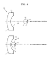
- FIG. 4 shows views of optical arrangements of a zoom illuminating system 102 employed in the imaging apparatus 1000 of FIG. 1 , according to another embodiment of the present invention, the optical arrangements respectively corresponding to a wide angle position and telephoto position of the zoom lens system 320 of the imaging apparatus 1000.
- the zoom illuminating system 102 includes a lens unit 140 including a first lens 141 and a second lens 142, and the light source 110, wherein the second lens 142 is disposed between the first lens 141 and the light source 110.
- the first lens 141 has negative refractive power, and has a meniscus shape, a surface of the first lens 141 facing the light source 110 being concave.
- the second lens 142 has positive refractive power, and has a meniscus shape, a surface of the second lens 142 facing the light source 110 being concave .
- the zoom illuminating systems 100 through 102 that may adjust the illumination ranges of light emitted from the light source 110 according to wide angle position and telephoto position photographing conditions are respectively realized according to the lens units 120 through 140 according to the embodiments of the present invention.
- the lens units 120, 130 and 140 include two lenses, but alternatively, the lens units 120, 130 and 140 may include only one lens, wherein a relative distance from the light source 110 to the lens is variable, or may include at least three lenses.
- Optical efficiency of the light source is high since the zoom illuminating system can illuminate a required range according to photographing conditions by adjusting an angle of beam spread of light in the light source from a short distance to a long distance.
- a wide view angle range is illuminated in a short distance and a narrow view angle range is illuminated in a long distance, the optical efficiency of the light source is increased, and thus, a visual range at night can be increased even with a low number of light sources.
- the imaging apparatus employing such a zoom illuminating system can efficiently photograph an object in a dark environment, and is suitable for a night monitoring system.
Landscapes
- Physics & Mathematics (AREA)
- General Physics & Mathematics (AREA)
- Optics & Photonics (AREA)
- Health & Medical Sciences (AREA)
- Toxicology (AREA)
- Engineering & Computer Science (AREA)
- Multimedia (AREA)
- Signal Processing (AREA)
- Stroboscope Apparatuses (AREA)
- Studio Devices (AREA)
- Lenses (AREA)
Abstract
Description
- The present invention relates to a zoom illuminating system capable of adjusting illumination according to imaging conditions, and an imaging apparatus employing the same.
- Recently, monitoring cameras for closed circuit television (CCTV) have been widely used in residential areas, commercial properties such as department stores and banks, and factory sites.
- A fixed focus lens having a fixed focal length or a zoom lens having a zoom function is used as an imaging lens of a monitoring camera, and infrared illumination for night photographing is also used in a monitoring camera.
- When a fixed focus lens is used, the fixed focus lens is a wide-angle lens having a large diameter in order to monitor a dark place with a wide range. Also, an illumination unit having a fixed illumination range is generally employed, and the illumination unit includes a plurality of light sources to illuminate a subject at night.
- The monitoring camera using the zoom lens require illumination covering a wide photographing range from a wide angle position to a telephoto position of the zoom lens. If an illumination unit having a fixed illumination range is used, light illumination efficiency is low since illumination aside a photographing range is not used. For example, light illustrated in a wide view angle at a telephoto position where only illumination in a narrow view angle is required is lost. Alternatively, a light source having a wide illumination range and a light source having a narrow illumination range may be used together to cover a wide photographing range from a wide angle position to a telephoto position.
- The present invention provides a zoom illumination system having an adjustable illumination range, and an imaging apparatus including the same.
- According to an aspect of the present invention, there is provided a zoom illuminating system having an adjustable illumination range and including: a light source; and a lens unit including at least one lens, wherein a distance from the light source to the at least one lens is variable.
- The light source may include at least one light emitting device emitting light in an infrared band.
- The lens unit may include a positive lens, wherein a distance from the light source to the positive lens may be variable.
- The lens unit may include: a first lens; and a second lens disposed between the first lens and the light source, wherein the illumination range may be adjusted by adjusting a distance between the first and second lenses.
- The first lens may be fixed and the second lens may be moved to adjust the distance between the first and second lenses.
- The first lens may be fixed and the light source may move together with the second lens.
- At least one of the first and second lenses may be a positive lens.
- The lens unit may include at least one aspherical surface. The second lens may be a spherical lens.
- According to another aspect of the present invention, there is provided an imaging apparatus including: the zoom illuminating system; a zoom lens system including a plurality of lens groups and zooming an image of an object as a distance between the plurality of lens groups varies; an image pickup device changing an optical image formed by the zoom lens system to an electric signal; and a control unit controlling zooming of the zoom lens system to be interlocked with adjusting of an illumination range of the zoom illuminating system.
- Magnification of the zoom lens system may be equal to or higher than 2.
- The above and other features and advantages of the present invention will become more apparent by describing in detail exemplary embodiments thereof with reference to the attached drawings in which:
-
FIG. 1 is a block diagram schematically illustrating an imaging apparatus according to an embodiment of the present invention; -
FIG. 2 shows views of optical arrangements of a zoom illuminating system employed in the imaging apparatus ofFIG. 1 , according to an embodiment of the present invention, the optical arrangements respectively corresponding to a wide angle position and telephoto position of a zoom lens system of the imaging apparatus ofFIG. 1 ; -
FIG. 3 shows views of optical arrangements of a zoom illuminating system employed in the imaging apparatus ofFIG. 1 , according to another embodiment of the present invention, the optical arrangements respectively corresponding to a wide angle position and telephoto position of a zoom lens system of the imaging apparatus ofFIG. 1 ; and -
FIG. 4 shows views of optical arrangements of a zoom illuminating system employed in the imaging apparatus ofFIG. 1 , according to another embodiment of the present invention, the optical arrangements respectively corresponding to a wide angle position and telephoto position of a zoom lens system of the imaging apparatus ofFIG. 1 . - Hereinafter, embodiments of the present invention will be described in detail with reference to the accompanying drawings. In the drawings, the sizes of elements may be exaggerated for clarity.
-
FIG. 1 is a block diagram schematically illustrating animaging apparatus 1000 according to an embodiment of the present invention. - The
imaging apparatus 1000 includes a zoomilluminating system 100 having a variable illumination range, animaging unit 300 including azoom lens system 320, and acontrol unit 200 controlling zooming of thezoom lens system 320 to be interlocked with adjusting of the illumination range of the zoomilluminating system 100. - In detail, the zoom
illuminating system 100 includes alight source 110 and alens unit 120 including at least one lens. A distance from thelight source 110 to the at least one lens is variable so as to adjust an illumination range of light emitted from thelight source 110. - A light emitting device emitting light in an infrared band, such as a light emitting diode (LED) or laser diode (LD) emitting light in a wavelength band of about 830 to 960 nm, may be employed as the
light source 110. One or morelight sources 110 may be used. - An angle of beam spread of a light emitting device employed as the
light source 110 is generally at least about 80°, and thelens unit 120 includes at least one positive lens so as to realize an illumination range in a view angle narrower than the angle of beam spread from such alight source 110. The illumination range of light emitted from thelight source 110 varies according to photographing conditions, and for example, thelens unit 120 may be driven such that the illumination range of a short distance having a wide angle of beam spread is formed according to the wide angle position photographing conditions, and the illumination range of a long distance having a narrow angle of beam spread is formed according to the telephoto position photographing conditions. - The
imaging unit 300 includes thezoom lens system 320 and animage pickup device 340. Thezoom lens system 320 includes a plurality of lens groups, and an image of an object may be zoomed as a distance between the lens groups varies. A number of lens groups forming thezoom lens system 320, or a type or number of lenses forming each lens group may be variously selected considering the optical performances such as magnification and aberration. Thezoom lens system 320 may have at least 2X zoom magnification. Theimage pickup device 340 converts an optical image formed by thezoom lens system 320 to an electric signal, and may be a charged coupled device (CCD) or a complementary metal-oxide semiconductor (CMOS). - The
control unit 200 controls zooming of thezoom lens system 320 and adjusting of an illumination range of thezoom lens system 320 to be interlocked with each other. Thecontrol unit 200 adjusts zoom magnifications, i.e., drives thezoom lens system 100 according to a command of a user, and drives the zoomilluminating system 100 to form a corresponding illumination range. In other words, thezoom lens system 320 is driven to have an illumination range having a wide angle of beam spread when thezoom lens system 320 is driven to have an optical arrangement corresponding to the wide angle position, and to have an illumination range having a narrow angle of beam spread when thezoom lens system 320 is driven to have an optical arrangement corresponding to the telephoto position. An angle of beam spread of light is widened at the wide angle position to increase an illumination area, and thus, illumination uniformity is obtained. An angle of beam spread of light is narrowed at the telephoto position so as to concentrate the light in a narrow area, and thus, illumination is increased. - Also, in order to adjust illumination, the
imaging apparatus 1000 may include an increased number oflight sources 110 or a plurality of zoomilluminating systems 100. - Hereinafter, embodiments of a zoom illuminating system employable by the
imaging apparatus 1000 ofFIG. 1 will be described together with lens data. A definition of an aspherical surface in the embodiments is as follows.
where, x denotes a distance from a vertex of a lens in an optical axis direction, y denotes a distance in a direction perpendicular to an optical axis, K denotes a conic constant, A, B, C, and D denote aspherical surface coefficients, and c' denotes an inverse number (1/R) of a radius of curvature at the vertex of lens. - In each lens data, D2 denotes a variable distance between lenses, Asphere denotes an aspherical surface, sphere denotes a spherical surface, and a unit of radius of curvature, thickness or distance, effective diameter, and focal length is mm. A refractive index relates to light in a wavelength band of e-ray.
-
FIG. 2 shows views of optical arrangements of the zoomilluminating system 100 employed in theimaging apparatus 1000 ofFIG. 1 , according to an embodiment of the present invention, the optical arrangements respectively corresponding to a wide angle position and telephoto position of thezoom lens system 320 of theimaging apparatus 1000. - The zoom
illuminating system 100 includes afirst lens 121, asecond lens 122, and thelight source 110, wherein thesecond lens 122 is disposed between thefirst lens 121 and thelight source 110. At least any one of the first andsecond lenses second lenses lens unit 120 vary and an illumination range is adjusted by adjusting a distance D2 between the first andsecond lenses first lens 121 is fixed and thesecond lens 122 moves along an optical axis to adjust the distance D2 from thefirst lens 121, and here, thelight source 110 moves together with thesecond lens 122. - Lens data is shown in Tables 1 through 3.
[Table 1] Surface # Radius of curvature Thickness or distance Refractive index Effective diameter Focal length 1 Asphere -19.1 16.7 1.523 23 36.5191 2 Sphere 1.00E+18 D2 23 3 Sphere -4.71 2.5 1.785 3 6.00214 4 Sphere 1.00E+18 3 [Table 2] Surface # A B K 1 -2.9e-006 -2.885e-009 -0.7100 [Table 3] D2 Half view angle (°) Wide angle 1.13 39.5 Telephoto 22.22 2.1 -
FIG. 3 shows views of optical arrangements of azoom illuminating system 101 employed in theimaging apparatus 1000 ofFIG. 1 , according to another embodiment of the present invention, the optical arrangements respectively corresponding to a wide angle position and telephoto position of thezoom lens system 320 of theimaging apparatus 1000. - The
zoom illuminating system 101 includes a lens unit 130 including afirst lens 131 and asecond lens 132, and thelight source 110, wherein thesecond lens 132 is disposed between thefirst lens 131 and thelight source 110. Thefirst lens 131 has positive refractive power, and has a meniscus shape, a surface of thefirst lens 131 facing thelight source 110 being concave. Thesecond lens 132 has negative refractive power, and has a meniscus shape, a surface of thesecond lens 132 facing thelight source 110 being concave.[Table 4] Surface # Radius of curvature Thickness or Distance Refractive index Effective diameter Focal length 1 Asphere 64.4798 30 1.516798 52 175.794 2 Sphere 193.7111 D2 47.5 3 Sphere 6.7851 9.54 1.516798 6.58 -106.184 4 Sphere 3.1668 2.15 [Table 5] # A B C K 1 1.64741e-009 -1.25884e-012 1.52640694e-015 -0.4615 [Table 6] D2 Half view angle (°) Wide angle 3 20.556 Telephoto 88.86 0.966 -
FIG. 4 shows views of optical arrangements of azoom illuminating system 102 employed in theimaging apparatus 1000 ofFIG. 1 , according to another embodiment of the present invention, the optical arrangements respectively corresponding to a wide angle position and telephoto position of thezoom lens system 320 of theimaging apparatus 1000. - The
zoom illuminating system 102 includes a lens unit 140 including afirst lens 141 and asecond lens 142, and thelight source 110, wherein thesecond lens 142 is disposed between thefirst lens 141 and thelight source 110. Thefirst lens 141 has negative refractive power, and has a meniscus shape, a surface of thefirst lens 141 facing thelight source 110 being concave. Thesecond lens 142 has positive refractive power, and has a meniscus shape, a surface of thesecond lens 142 facing thelight source 110 being concave .[Table 7] Surface # Radius of curvature Thickness or distance Refractive index Effective diameter Focal length 1 Asphere 58.2121 10 1.516798 52 -70.9663 2 Sphere 21.0185 D2 47.5 3 Sphere 6.3805 9.847 1.516798 6.58 25.652 4 Sphere 5.9661 2.15 # A B C K 1 1.0879e-008 -8.3994e-011 1.0160e-014 -0.288337 [Table 9] D2 Half view angle (°) Wide angle 32.8570 35.70669 Telephoto 2.70815 25.11483 - As such, the
zoom illuminating systems 100 through 102 that may adjust the illumination ranges of light emitted from thelight source 110 according to wide angle position and telephoto position photographing conditions are respectively realized according to thelens units 120 through 140 according to the embodiments of the present invention. - In the above embodiments, the
lens units 120, 130 and 140 include two lenses, but alternatively, thelens units 120, 130 and 140 may include only one lens, wherein a relative distance from thelight source 110 to the lens is variable, or may include at least three lenses. - Optical efficiency of the light source is high since the zoom illuminating system can illuminate a required range according to photographing conditions by adjusting an angle of beam spread of light in the light source from a short distance to a long distance.
- Also, since a wide view angle range is illuminated in a short distance and a narrow view angle range is illuminated in a long distance, the optical efficiency of the light source is increased, and thus, a visual range at night can be increased even with a low number of light sources.
- Accordingly, the imaging apparatus employing such a zoom illuminating system can efficiently photograph an object in a dark environment, and is suitable for a night monitoring system.
Claims (11)
- A zoom illuminating system (100, 101, 102) having an adjustable illumination range and comprising:a light source (110); anda lens unit (120, 130, 140) comprising at least one lens, wherein a distance from the light source (110) to the at least one lens is variable.
- The zoom illuminating system (100, 101, 102) of claim 1, wherein the light source (110) comprises at least one light emitting device emitting light in an infrared band.
- The zoom illuminating system (100, 101, 102) of claim 1 or claim 2, wherein the lens unit (120, 130, 140) comprises a positive lens, wherein a distance from the light source to the positive lens is variable.
- The zoom illuminating system (100, 101, 102) of claim 1, claim 2 or claim 3, wherein the lens unit (120, 130, 140) comprises:a first lens (121, 131, 141); anda second lens (122, 132, 142) disposed between the first lens (121, 131, 141) and the light source (110),wherein the illumination range is adjusted by adjusting a distance between the first (121, 131, 141) and second (22, 132, 142) lenses.
- The zoom illuminating system (100, 101 102) of claim 4, wherein the first lens (121, 131, 141) is fixed and the second (122, 132, 142) lens is moved to adjust the distance between the first (121, 131, 141) and second (122, 132, 142) lenses.
- The zoom illuminating system (100, 101, 102) of claim 5, wherein the first lens (121, 131, 141) is fixed and the light source (110) moves together with the second (122, 132, 142) lens.
- The zoom illuminating system (100, 101, 102) of claim 4, wherein at least one of the first (121, 131, 141) and second (122, 132, 142) lenses is a positive lens.
- The zoom illuminating system (100, 101, 102) of any preceding claim, wherein the lens unit (120, 130, 140) comprises at least one aspherical surface.
- The zoom illuminating system (100, 101, 102) of claim 8, wherein the second lens (122, 132, 142) is a spherical lens.
- An imaging apparatus (1000) comprising:the zoom illuminating system (100, 101, 102) of any one of the preceding claims;a zoom lens system (320) comprising a plurality of lens groups, the zoom lens system (320) being arranged to zoom an image of an object as a distance between the plurality of lens groups varies;an image pickup device (340) changing an optical image formed by the zoom lens system (320) to an electric signal; anda control unit (200) arranged to control zooming of the zoom lens system (320) so that it is interlocked with the adjustment of an illumination range of the zoom illuminating system (100, 101, 102).
- The imaging apparatus (1000) of claim 10, wherein the magnification of the zoom lens system (320) is equal to or higher than 2.
Applications Claiming Priority (1)
| Application Number | Priority Date | Filing Date | Title |
|---|---|---|---|
| KR1020110121733A KR101289797B1 (en) | 2011-11-21 | 2011-11-21 | Zoom illuminating system and imaging apparatus employing the same |
Publications (2)
| Publication Number | Publication Date |
|---|---|
| EP2594977A1 true EP2594977A1 (en) | 2013-05-22 |
| EP2594977B1 EP2594977B1 (en) | 2023-06-14 |
Family
ID=47323907
Family Applications (1)
| Application Number | Title | Priority Date | Filing Date |
|---|---|---|---|
| EP12193481.4A Active EP2594977B1 (en) | 2011-11-21 | 2012-11-20 | Zoom illuminating system and imaging apparatus employing the same |
Country Status (4)
| Country | Link |
|---|---|
| US (1) | US8885095B2 (en) |
| EP (1) | EP2594977B1 (en) |
| KR (1) | KR101289797B1 (en) |
| CN (1) | CN103135231A (en) |
Families Citing this family (9)
| Publication number | Priority date | Publication date | Assignee | Title |
|---|---|---|---|---|
| TWI627493B (en) * | 2014-10-31 | 2018-06-21 | 高準精密工業股份有限公司 | Combined optical lens and optical imaging device using the same |
| US9992396B1 (en) | 2015-02-02 | 2018-06-05 | Apple Inc. | Focusing lighting module |
| KR102449568B1 (en) | 2018-01-09 | 2022-10-04 | 한화테크윈 주식회사 | Lighting control method, apparatus and computer program |
| CN108225277A (en) * | 2018-03-09 | 2018-06-29 | 深圳臻迪信息技术有限公司 | Image acquiring method, vision positioning method, device, the unmanned plane of unmanned plane |
| JP2019168655A (en) * | 2018-03-26 | 2019-10-03 | キヤノン株式会社 | Illumination optical system and illumination device using the same |
| CN110320728A (en) * | 2019-07-09 | 2019-10-11 | 林璧光 | A kind of light-emitting angle can multi-gear adjustment LED photography luminaire |
| WO2022056889A1 (en) * | 2020-09-19 | 2022-03-24 | Huawei Technologies Co., Ltd. | Optical apparatus |
| CN115793217B (en) * | 2022-11-24 | 2026-05-19 | 中山联合光电研究院有限公司 | Zoom lens and imaging device |
| CN121028351A (en) * | 2023-12-31 | 2025-11-28 | 安徽光智科技有限公司 | A long-wave infrared continuous zoom microscope lens |
Citations (3)
| Publication number | Priority date | Publication date | Assignee | Title |
|---|---|---|---|---|
| JPH0876017A (en) * | 1994-09-05 | 1996-03-22 | Nikon Corp | Zoom illuminator |
| US20060055818A1 (en) * | 2004-09-15 | 2006-03-16 | Yi-Feng Hwang | Flash module, camera, and method for illuminating an object during flash photography |
| WO2006031037A1 (en) * | 2004-09-13 | 2006-03-23 | Myung-Koo Kang | Illuminating device using light source device |
Family Cites Families (22)
| Publication number | Priority date | Publication date | Assignee | Title |
|---|---|---|---|---|
| US3798668A (en) * | 1972-10-05 | 1974-03-19 | Bell & Howell Co | Camera light |
| US4423940A (en) * | 1981-01-20 | 1984-01-03 | West Electric Co., Ltd. | Photographic equipment |
| US5378883A (en) * | 1991-07-19 | 1995-01-03 | Omniplanar Inc. | Omnidirectional wide range hand held bar code reader |
| US5539622A (en) * | 1992-03-12 | 1996-07-23 | Asahi Kogaku Kogyo Kabushiki Kaisha | Strobe device |
| JPH0996856A (en) * | 1995-07-26 | 1997-04-08 | Asahi Optical Co Ltd | Zoom strobe device |
| JP2002031832A (en) * | 2000-07-14 | 2002-01-31 | Canon Inc | camera |
| JP2002090822A (en) * | 2000-09-13 | 2002-03-27 | Fuji Photo Film Co Ltd | Strobe device and camera |
| JP2002236307A (en) | 2001-02-09 | 2002-08-23 | Asahi Optical Co Ltd | Zoom strobe device |
| ITMI20021625A1 (en) * | 2002-07-23 | 2004-01-23 | Coemar Spa | BRIGHT PROJECTOR WITH MEANS TO PERIMETALLY DELIMIT THE BEAM OF LIGHT EMITTED |
| JP3971270B2 (en) * | 2002-08-20 | 2007-09-05 | ペンタックス株式会社 | Zoom wide-angle zoom strobe device and zoom compact camera with zoom strobe device |
| KR100518250B1 (en) | 2003-05-06 | 2005-10-20 | 김두근 | lighting apparatus which diffuse infrared rays |
| US7298970B2 (en) * | 2004-08-30 | 2007-11-20 | Eastman Kodak Company | Zoom flash with variable focus lens |
| US7400390B2 (en) * | 2004-11-29 | 2008-07-15 | Applied Materials, Israel, Ltd. | Inspection system and a method for aerial reticle inspection |
| CN2783373Y (en) * | 2005-03-23 | 2006-05-24 | 刘方 | Zoom illumination device matched with zoom video camera |
| CN101162816B (en) * | 2007-09-13 | 2010-09-01 | 番禺得意精密电子工业有限公司 | Electric connector |
| JP2009186596A (en) * | 2008-02-04 | 2009-08-20 | Sony Corp | Imaging lens system and imaging apparatus using the same |
| KR101066147B1 (en) | 2009-03-31 | 2011-09-20 | (주)보임기술 | LED reflective lens |
| WO2011059127A1 (en) * | 2009-11-13 | 2011-05-19 | 한국과학기술연구원 | Infrared sensor and sensing method using the same |
| KR20110094377A (en) | 2010-02-16 | 2011-08-24 | 유창산업기계(주) | Array Variable Radial Angle Lighting |
| KR101013466B1 (en) * | 2010-07-02 | 2011-02-14 | 주식회사보다텍 | Automatic Lighting Control System Using Zoom Angle of View |
| CN101923212A (en) * | 2010-07-06 | 2010-12-22 | 山东神戎电子股份有限公司 | High-definition laser night-vision viewer |
| CN202008569U (en) * | 2011-03-21 | 2011-10-12 | 福州开发区鸿发光电子技术有限公司 | Search lighting angle synchronously-followed energy-saving type infrared lighting system |
-
2011
- 2011-11-21 KR KR1020110121733A patent/KR101289797B1/en active Active
-
2012
- 2012-08-30 US US13/598,879 patent/US8885095B2/en active Active
- 2012-10-29 CN CN2012104219343A patent/CN103135231A/en active Pending
- 2012-11-20 EP EP12193481.4A patent/EP2594977B1/en active Active
Patent Citations (3)
| Publication number | Priority date | Publication date | Assignee | Title |
|---|---|---|---|---|
| JPH0876017A (en) * | 1994-09-05 | 1996-03-22 | Nikon Corp | Zoom illuminator |
| WO2006031037A1 (en) * | 2004-09-13 | 2006-03-23 | Myung-Koo Kang | Illuminating device using light source device |
| US20060055818A1 (en) * | 2004-09-15 | 2006-03-16 | Yi-Feng Hwang | Flash module, camera, and method for illuminating an object during flash photography |
Also Published As
| Publication number | Publication date |
|---|---|
| KR101289797B1 (en) | 2013-07-26 |
| CN103135231A (en) | 2013-06-05 |
| US8885095B2 (en) | 2014-11-11 |
| KR20130056015A (en) | 2013-05-29 |
| US20130128096A1 (en) | 2013-05-23 |
| EP2594977B1 (en) | 2023-06-14 |
Similar Documents
| Publication | Publication Date | Title |
|---|---|---|
| EP2594977B1 (en) | Zoom illuminating system and imaging apparatus employing the same | |
| US11054618B2 (en) | Optical imaging system and portable electronic device including the same | |
| US6870690B1 (en) | Dual-band lens | |
| KR101762006B1 (en) | Optical system and mobile device including a plurality of optical systems with different field of view | |
| KR102842065B1 (en) | Optical imaging system | |
| TWM511632U (en) | Camera module and electronic device | |
| US9594235B2 (en) | Zoom lens system | |
| KR20260019596A (en) | Optical Imaging System | |
| KR20130054006A (en) | Infrared optical lens system | |
| KR20240057215A (en) | Optical Imaging System | |
| US9297986B2 (en) | Wide angle lens system and electronic apparatus having the same | |
| EP4270079A1 (en) | Optical system | |
| KR20190035634A (en) | Optical system and portable electronic device including the same | |
| US7532417B2 (en) | Dual field of view lens system | |
| US20060279857A1 (en) | Adjustable optical system and method for using and manufacturing such | |
| KR20220009663A (en) | Optical system and camera module including the same | |
| US11774732B2 (en) | Continuous zoom afocal lens assembly | |
| US12158634B2 (en) | Optical lens, camera module, and terminal | |
| CN111308741B (en) | Small concave imaging device and imaging method based on liquid crystal lens | |
| KR20220045716A (en) | Optical system and camera module inclduing the same | |
| KR102748955B1 (en) | Optical system | |
| CN120215105B (en) | A multifunctional zoom eyepiece with dual image planes and large magnification | |
| EP4607259A1 (en) | Optical system, optical device, and camera module including same | |
| KR20210114794A (en) | Zoom lens system | |
| KR20220050406A (en) | Infrared zoom lens module |
Legal Events
| Date | Code | Title | Description |
|---|---|---|---|
| PUAI | Public reference made under article 153(3) epc to a published international application that has entered the european phase |
Free format text: ORIGINAL CODE: 0009012 |
|
| 17P | Request for examination filed |
Effective date: 20121120 |
|
| AK | Designated contracting states |
Kind code of ref document: A1 Designated state(s): AL AT BE BG CH CY CZ DE DK EE ES FI FR GB GR HR HU IE IS IT LI LT LU LV MC MK MT NL NO PL PT RO RS SE SI SK SM TR |
|
| AX | Request for extension of the european patent |
Extension state: BA ME |
|
| RAP1 | Party data changed (applicant data changed or rights of an application transferred) |
Owner name: HANWHA TECHWIN CO., LTD. |
|
| STAA | Information on the status of an ep patent application or granted ep patent |
Free format text: STATUS: EXAMINATION IS IN PROGRESS |
|
| 17Q | First examination report despatched |
Effective date: 20161116 |
|
| RAP1 | Party data changed (applicant data changed or rights of an application transferred) |
Owner name: HANWHA TECHWIN CO., LTD. |
|
| GRAP | Despatch of communication of intention to grant a patent |
Free format text: ORIGINAL CODE: EPIDOSNIGR1 |
|
| STAA | Information on the status of an ep patent application or granted ep patent |
Free format text: STATUS: GRANT OF PATENT IS INTENDED |
|
| INTG | Intention to grant announced |
Effective date: 20230104 |
|
| GRAS | Grant fee paid |
Free format text: ORIGINAL CODE: EPIDOSNIGR3 |
|
| GRAA | (expected) grant |
Free format text: ORIGINAL CODE: 0009210 |
|
| STAA | Information on the status of an ep patent application or granted ep patent |
Free format text: STATUS: THE PATENT HAS BEEN GRANTED |
|
| AK | Designated contracting states |
Kind code of ref document: B1 Designated state(s): AL AT BE BG CH CY CZ DE DK EE ES FI FR GB GR HR HU IE IS IT LI LT LU LV MC MK MT NL NO PL PT RO RS SE SI SK SM TR |
|
| REG | Reference to a national code |
Ref country code: GB Ref legal event code: FG4D |
|
| REG | Reference to a national code |
Ref country code: CH Ref legal event code: EP |
|
| REG | Reference to a national code |
Ref country code: DE Ref legal event code: R096 Ref document number: 602012079745 Country of ref document: DE |
|
| REG | Reference to a national code |
Ref country code: AT Ref legal event code: REF Ref document number: 1579645 Country of ref document: AT Kind code of ref document: T Effective date: 20230715 |
|
| REG | Reference to a national code |
Ref country code: DE Ref legal event code: R081 Ref document number: 602012079745 Country of ref document: DE Owner name: HANWHA VISION CO., LTD., SEONGNAM-SI, KR Free format text: FORMER OWNER: HANWHA TECHWIN CO., LTD., SEONGNAM-SI, GYEONGGI-DO, KR |
|
| REG | Reference to a national code |
Ref country code: LT Ref legal event code: MG9D |
|
| REG | Reference to a national code |
Ref country code: NL Ref legal event code: MP Effective date: 20230614 |
|
| PG25 | Lapsed in a contracting state [announced via postgrant information from national office to epo] |
Ref country code: SE Free format text: LAPSE BECAUSE OF FAILURE TO SUBMIT A TRANSLATION OF THE DESCRIPTION OR TO PAY THE FEE WITHIN THE PRESCRIBED TIME-LIMIT Effective date: 20230614 Ref country code: NO Free format text: LAPSE BECAUSE OF FAILURE TO SUBMIT A TRANSLATION OF THE DESCRIPTION OR TO PAY THE FEE WITHIN THE PRESCRIBED TIME-LIMIT Effective date: 20230914 Ref country code: ES Free format text: LAPSE BECAUSE OF FAILURE TO SUBMIT A TRANSLATION OF THE DESCRIPTION OR TO PAY THE FEE WITHIN THE PRESCRIBED TIME-LIMIT Effective date: 20230614 |
|
| REG | Reference to a national code |
Ref country code: AT Ref legal event code: MK05 Ref document number: 1579645 Country of ref document: AT Kind code of ref document: T Effective date: 20230614 |
|
| PG25 | Lapsed in a contracting state [announced via postgrant information from national office to epo] |
Ref country code: RS Free format text: LAPSE BECAUSE OF FAILURE TO SUBMIT A TRANSLATION OF THE DESCRIPTION OR TO PAY THE FEE WITHIN THE PRESCRIBED TIME-LIMIT Effective date: 20230614 Ref country code: NL Free format text: LAPSE BECAUSE OF FAILURE TO SUBMIT A TRANSLATION OF THE DESCRIPTION OR TO PAY THE FEE WITHIN THE PRESCRIBED TIME-LIMIT Effective date: 20230614 Ref country code: LV Free format text: LAPSE BECAUSE OF FAILURE TO SUBMIT A TRANSLATION OF THE DESCRIPTION OR TO PAY THE FEE WITHIN THE PRESCRIBED TIME-LIMIT Effective date: 20230614 Ref country code: LT Free format text: LAPSE BECAUSE OF FAILURE TO SUBMIT A TRANSLATION OF THE DESCRIPTION OR TO PAY THE FEE WITHIN THE PRESCRIBED TIME-LIMIT Effective date: 20230614 Ref country code: HR Free format text: LAPSE BECAUSE OF FAILURE TO SUBMIT A TRANSLATION OF THE DESCRIPTION OR TO PAY THE FEE WITHIN THE PRESCRIBED TIME-LIMIT Effective date: 20230614 Ref country code: GR Free format text: LAPSE BECAUSE OF FAILURE TO SUBMIT A TRANSLATION OF THE DESCRIPTION OR TO PAY THE FEE WITHIN THE PRESCRIBED TIME-LIMIT Effective date: 20230915 |
|
| PG25 | Lapsed in a contracting state [announced via postgrant information from national office to epo] |
Ref country code: FI Free format text: LAPSE BECAUSE OF FAILURE TO SUBMIT A TRANSLATION OF THE DESCRIPTION OR TO PAY THE FEE WITHIN THE PRESCRIBED TIME-LIMIT Effective date: 20230614 |
|
| PG25 | Lapsed in a contracting state [announced via postgrant information from national office to epo] |
Ref country code: SK Free format text: LAPSE BECAUSE OF FAILURE TO SUBMIT A TRANSLATION OF THE DESCRIPTION OR TO PAY THE FEE WITHIN THE PRESCRIBED TIME-LIMIT Effective date: 20230614 |
|
| PG25 | Lapsed in a contracting state [announced via postgrant information from national office to epo] |
Ref country code: IS Free format text: LAPSE BECAUSE OF FAILURE TO SUBMIT A TRANSLATION OF THE DESCRIPTION OR TO PAY THE FEE WITHIN THE PRESCRIBED TIME-LIMIT Effective date: 20231014 |
|
| PG25 | Lapsed in a contracting state [announced via postgrant information from national office to epo] |
Ref country code: SM Free format text: LAPSE BECAUSE OF FAILURE TO SUBMIT A TRANSLATION OF THE DESCRIPTION OR TO PAY THE FEE WITHIN THE PRESCRIBED TIME-LIMIT Effective date: 20230614 Ref country code: SK Free format text: LAPSE BECAUSE OF FAILURE TO SUBMIT A TRANSLATION OF THE DESCRIPTION OR TO PAY THE FEE WITHIN THE PRESCRIBED TIME-LIMIT Effective date: 20230614 Ref country code: RO Free format text: LAPSE BECAUSE OF FAILURE TO SUBMIT A TRANSLATION OF THE DESCRIPTION OR TO PAY THE FEE WITHIN THE PRESCRIBED TIME-LIMIT Effective date: 20230614 Ref country code: PT Free format text: LAPSE BECAUSE OF FAILURE TO SUBMIT A TRANSLATION OF THE DESCRIPTION OR TO PAY THE FEE WITHIN THE PRESCRIBED TIME-LIMIT Effective date: 20231016 Ref country code: IS Free format text: LAPSE BECAUSE OF FAILURE TO SUBMIT A TRANSLATION OF THE DESCRIPTION OR TO PAY THE FEE WITHIN THE PRESCRIBED TIME-LIMIT Effective date: 20231014 Ref country code: EE Free format text: LAPSE BECAUSE OF FAILURE TO SUBMIT A TRANSLATION OF THE DESCRIPTION OR TO PAY THE FEE WITHIN THE PRESCRIBED TIME-LIMIT Effective date: 20230614 Ref country code: CZ Free format text: LAPSE BECAUSE OF FAILURE TO SUBMIT A TRANSLATION OF THE DESCRIPTION OR TO PAY THE FEE WITHIN THE PRESCRIBED TIME-LIMIT Effective date: 20230614 Ref country code: AT Free format text: LAPSE BECAUSE OF FAILURE TO SUBMIT A TRANSLATION OF THE DESCRIPTION OR TO PAY THE FEE WITHIN THE PRESCRIBED TIME-LIMIT Effective date: 20230614 |
|
| PG25 | Lapsed in a contracting state [announced via postgrant information from national office to epo] |
Ref country code: PL Free format text: LAPSE BECAUSE OF FAILURE TO SUBMIT A TRANSLATION OF THE DESCRIPTION OR TO PAY THE FEE WITHIN THE PRESCRIBED TIME-LIMIT Effective date: 20230614 |
|
| REG | Reference to a national code |
Ref country code: DE Ref legal event code: R097 Ref document number: 602012079745 Country of ref document: DE |
|
| PLBE | No opposition filed within time limit |
Free format text: ORIGINAL CODE: 0009261 |
|
| STAA | Information on the status of an ep patent application or granted ep patent |
Free format text: STATUS: NO OPPOSITION FILED WITHIN TIME LIMIT |
|
| PG25 | Lapsed in a contracting state [announced via postgrant information from national office to epo] |
Ref country code: DK Free format text: LAPSE BECAUSE OF FAILURE TO SUBMIT A TRANSLATION OF THE DESCRIPTION OR TO PAY THE FEE WITHIN THE PRESCRIBED TIME-LIMIT Effective date: 20230614 |
|
| PG25 | Lapsed in a contracting state [announced via postgrant information from national office to epo] |
Ref country code: SI Free format text: LAPSE BECAUSE OF FAILURE TO SUBMIT A TRANSLATION OF THE DESCRIPTION OR TO PAY THE FEE WITHIN THE PRESCRIBED TIME-LIMIT Effective date: 20230614 |
|
| 26N | No opposition filed |
Effective date: 20240315 |
|
| PG25 | Lapsed in a contracting state [announced via postgrant information from national office to epo] |
Ref country code: SI Free format text: LAPSE BECAUSE OF FAILURE TO SUBMIT A TRANSLATION OF THE DESCRIPTION OR TO PAY THE FEE WITHIN THE PRESCRIBED TIME-LIMIT Effective date: 20230614 Ref country code: IT Free format text: LAPSE BECAUSE OF FAILURE TO SUBMIT A TRANSLATION OF THE DESCRIPTION OR TO PAY THE FEE WITHIN THE PRESCRIBED TIME-LIMIT Effective date: 20230614 |
|
| REG | Reference to a national code |
Ref country code: CH Ref legal event code: PL |
|
| PG25 | Lapsed in a contracting state [announced via postgrant information from national office to epo] |
Ref country code: MC Free format text: LAPSE BECAUSE OF FAILURE TO SUBMIT A TRANSLATION OF THE DESCRIPTION OR TO PAY THE FEE WITHIN THE PRESCRIBED TIME-LIMIT Effective date: 20230614 |
|
| PG25 | Lapsed in a contracting state [announced via postgrant information from national office to epo] |
Ref country code: LU Free format text: LAPSE BECAUSE OF NON-PAYMENT OF DUE FEES Effective date: 20231120 |
|
| PG25 | Lapsed in a contracting state [announced via postgrant information from national office to epo] |
Ref country code: CH Free format text: LAPSE BECAUSE OF NON-PAYMENT OF DUE FEES Effective date: 20231130 |
|
| PG25 | Lapsed in a contracting state [announced via postgrant information from national office to epo] |
Ref country code: MC Free format text: LAPSE BECAUSE OF FAILURE TO SUBMIT A TRANSLATION OF THE DESCRIPTION OR TO PAY THE FEE WITHIN THE PRESCRIBED TIME-LIMIT Effective date: 20230614 Ref country code: LU Free format text: LAPSE BECAUSE OF NON-PAYMENT OF DUE FEES Effective date: 20231120 Ref country code: CH Free format text: LAPSE BECAUSE OF NON-PAYMENT OF DUE FEES Effective date: 20231130 |
|
| REG | Reference to a national code |
Ref country code: BE Ref legal event code: MM Effective date: 20231130 |
|
| REG | Reference to a national code |
Ref country code: IE Ref legal event code: MM4A |
|
| PG25 | Lapsed in a contracting state [announced via postgrant information from national office to epo] |
Ref country code: IE Free format text: LAPSE BECAUSE OF NON-PAYMENT OF DUE FEES Effective date: 20231120 |
|
| PG25 | Lapsed in a contracting state [announced via postgrant information from national office to epo] |
Ref country code: BE Free format text: LAPSE BECAUSE OF NON-PAYMENT OF DUE FEES Effective date: 20231130 |
|
| PG25 | Lapsed in a contracting state [announced via postgrant information from national office to epo] |
Ref country code: IE Free format text: LAPSE BECAUSE OF NON-PAYMENT OF DUE FEES Effective date: 20231120 Ref country code: BE Free format text: LAPSE BECAUSE OF NON-PAYMENT OF DUE FEES Effective date: 20231130 |
|
| PG25 | Lapsed in a contracting state [announced via postgrant information from national office to epo] |
Ref country code: BG Free format text: LAPSE BECAUSE OF FAILURE TO SUBMIT A TRANSLATION OF THE DESCRIPTION OR TO PAY THE FEE WITHIN THE PRESCRIBED TIME-LIMIT Effective date: 20230614 |
|
| PG25 | Lapsed in a contracting state [announced via postgrant information from national office to epo] |
Ref country code: BG Free format text: LAPSE BECAUSE OF FAILURE TO SUBMIT A TRANSLATION OF THE DESCRIPTION OR TO PAY THE FEE WITHIN THE PRESCRIBED TIME-LIMIT Effective date: 20230614 |
|
| PG25 | Lapsed in a contracting state [announced via postgrant information from national office to epo] |
Ref country code: CY Free format text: LAPSE BECAUSE OF FAILURE TO SUBMIT A TRANSLATION OF THE DESCRIPTION OR TO PAY THE FEE WITHIN THE PRESCRIBED TIME-LIMIT; INVALID AB INITIO Effective date: 20121120 |
|
| PG25 | Lapsed in a contracting state [announced via postgrant information from national office to epo] |
Ref country code: HU Free format text: LAPSE BECAUSE OF FAILURE TO SUBMIT A TRANSLATION OF THE DESCRIPTION OR TO PAY THE FEE WITHIN THE PRESCRIBED TIME-LIMIT; INVALID AB INITIO Effective date: 20121120 |
|
| PG25 | Lapsed in a contracting state [announced via postgrant information from national office to epo] |
Ref country code: TR Free format text: LAPSE BECAUSE OF FAILURE TO SUBMIT A TRANSLATION OF THE DESCRIPTION OR TO PAY THE FEE WITHIN THE PRESCRIBED TIME-LIMIT Effective date: 20230614 |
|
| PGFP | Annual fee paid to national office [announced via postgrant information from national office to epo] |
Ref country code: DE Payment date: 20251020 Year of fee payment: 14 |
|
| PGFP | Annual fee paid to national office [announced via postgrant information from national office to epo] |
Ref country code: GB Payment date: 20251023 Year of fee payment: 14 |
|
| PGFP | Annual fee paid to national office [announced via postgrant information from national office to epo] |
Ref country code: FR Payment date: 20251021 Year of fee payment: 14 |