EP2594961B1 - Surface contamination monitoring system and method - Google Patents
Surface contamination monitoring system and method Download PDFInfo
- Publication number
- EP2594961B1 EP2594961B1 EP12193090.3A EP12193090A EP2594961B1 EP 2594961 B1 EP2594961 B1 EP 2594961B1 EP 12193090 A EP12193090 A EP 12193090A EP 2594961 B1 EP2594961 B1 EP 2594961B1
- Authority
- EP
- European Patent Office
- Prior art keywords
- photosensor
- monitored subject
- surface contamination
- contamination monitoring
- shielding
- Prior art date
- Legal status (The legal status is an assumption and is not a legal conclusion. Google has not performed a legal analysis and makes no representation as to the accuracy of the status listed.)
- Active
Links
Images










Classifications
-
- G—PHYSICS
- G01—MEASURING; TESTING
- G01T—MEASUREMENT OF NUCLEAR OR X-RADIATION
- G01T1/00—Measuring X-radiation, gamma radiation, corpuscular radiation, or cosmic radiation
- G01T1/16—Measuring radiation intensity
- G01T1/17—Circuit arrangements not adapted to a particular type of detector
-
- G—PHYSICS
- G01—MEASURING; TESTING
- G01T—MEASUREMENT OF NUCLEAR OR X-RADIATION
- G01T1/00—Measuring X-radiation, gamma radiation, corpuscular radiation, or cosmic radiation
- G01T1/16—Measuring radiation intensity
- G01T1/161—Applications in the field of nuclear medicine, e.g. in vivo counting
- G01T1/163—Whole-body counters
-
- G—PHYSICS
- G01—MEASURING; TESTING
- G01T—MEASUREMENT OF NUCLEAR OR X-RADIATION
- G01T3/00—Measuring neutron radiation
Definitions
- the present invention generally relates to systems and methods for radiation detection in applications of surface contamination monitoring. Without limitation, this may include systems/methods for improving the accuracy of radiation contamination monitors used to determine surface contamination on monitored subjects, such as in the application of whole-body contamination monitoring of the body of a worker in an industrial environment.
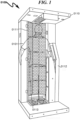
- a typical prior art monitoring portal utilizes an array of radiation detectors ( 0111 ), a number of which detect gamma radiation.
- the array ( 0111 ) allows a monitored subject (radiation worker) ( 0101 ) to enter the device and stand with one side of the worker's body positioned before the detector array (0111).
- An arm, side leg, and hand monitoring array ( 0112 ) is also present in the depiction. As shown, the monitored subject ( 0101 ) is facing the detector array ( 0111 ), with their right hand and arm inserted in the array ( 0112 ).
- Detectors ( 0113 ) on the base of the monitoring portal ( 0110 ) detect contamination that may be present on the monitored subject's ( 0101 ) feet.
- the monitored subject's ( 0101 ) anterior surface, right arm, right outside leg, and feet are being monitored for surface contamination.
- the monitored subject ( 0101 ) turns with their posterior surface against the detector array ( 0111 ), with their left hand and arm inserted in the array ( 0112 ).
- the measurement data is processed by an automated computing device, which logs the measurements and signals a contamination alarm if necessary.
- On-site calibration of such detection devices is crucial to the accuracy of its radiation measurements.
- gamma-ray background radiation is always present at levels that vary from physical location to location.
- an on-site calibration routine utilizing one or more monitored subjects (who are known not to be contaminated) is typically performed to determine the existing background radiation properties and their effects on occupant self-shielding.
- the predetermined calibration factors to calculate the effects caused by the fact that the monitored subject's body has a shielding effect on the detector array ( 0111 ) may not fully describe the self-shielding on-site.
- the monitored subject's body ( 0101 ) When standing in front of the detector array ( 0111 ), the monitored subject's body ( 0101 ) will absorb and/or scatter a certain amount of the background gamma radiation. This causes the resulting measured radiation net count rate (NCR) value to be different than the actual count rate (ACR) present on the monitored subject's body, because the background radiation (though no longer being detected at the same rate as before the monitored subject entered the device) is still being deducted from the measured counts.
- NCR measured radiation net count rate
- ACR actual count rate
- a common method currently employed in an attempt to deal with this problem is to apply a single correction factor to the measurement that compensates for this whole-body shielding effect upon the detectors.
- a group of monitored subjects who are known not to be contaminated is surveyed and an average "standard" monitored subject profile is obtained.
- This "standard" monitored subject profile is intended to compensate for the average shielding effect that a body has on the measured background radiation.
- a single correction factor is applied to the measured radiation net count rate determinations. While this is an improvement over previous methods of measured radiation count rate determinations, it still does not account for the effects of varying body shapes and sizes.
- NCR measured radiation net count rate
- ACR actual count rate
- NCR measured radiation net count rate
- the average "standard" monitored subject profile does not compensate for the effects that various body heights and thicknesses have on the sensitivity and accuracy of the various sections of the detector array. For example, to increase sensitivity in the detectors, various detectors within the array will be grouped together to form a larger effective scintillating volume. Therefore, a monitored subject that is shorter than average or that has a slight frame will leave certain detector groupings exposed to (or unshielded from) the background counts. Thus, while the average "standard” monitored subject profile compensation assumes that these certain detector groupings should be experiencing some shielding, the resulting net count rate (NCR) will be greater than actual.
- NCR net count rate
- NCR measured radiation net count rate
- this average "standard" monitored subject profile does not account for varying thickness of individual monitored subjects.
- a monitored subject with an athletic build small waist and midsection (gut) area, but large upper body
- the portions of the detector array near the chest area in reality, require a different correction factor than those near the monitored subject's waist. This requirement is reversed in the situation with a monitored subject having an excessively large midsection and relatively small upper body. Accordingly, the current "one-size-fits-all" approach does not adequately compensate for varying monitored subject bodies.
- the calibration factor represents the ratio of K-42 counts per minute per pCi of a phantom to K-42 counts per minute per pCi of a subject and was approximated using a linear equation taking into account the height and weight.
- JPH0392788 e.g. discloses a surface contamination monitoring system comprising: a radiation detector array and a computing device; wherein said radiation detector array is configured to monitor radioisotope surface-contamination of a monitored subject, said computing device is configured to compute a corrected net count rate, based upon the net count rate and said corrected net count rate comprising a correction factor: an attenuation factor, comprising a height value and a plurality of thickness values; the values representing physical characteristics of said monitored subject.
- the objectives of the present invention are (among others) to circumvent the deficiencies in the prior art.
- the objectives further are:
- One embodiment disclosed herein is a whole-body surface contamination monitoring system, as claimed in claim 1.
- the present invention further details a surface contamination monitoring method as claimed in claim 12.
- the method (300) is generally illustrated in Figure 3 .
- computing device means any computer processing device capable of executing program instructions stored on a computer readable medium. While Personal Computer (PC) construction may be optimal in many circumstances, the present invention is not limited to this particular form of construction and the term "computing device” and “PC” should be given their broadest possible definitions in this context.
- PC Personal Computer
- sensors for the determination of height and thickness values for a monitored subject
- the term "sensor” or “sensor device” should be broadly construed to incorporate the use of video and still camera apparatus that may be used to perform equivalent orthogonal body height/thickness analysis of the monitored subject.
- Some exemplary sensors anticipated for use in various embodiments of the present invention include but are not limited to: photosensor; infrared reflectivity photosensor; time-of-flight photosensor; angular detection photosensor; multi-beam photosensor; orthogonal array photosensor; ultrasonic sensor; and mechanical contact sensor.
- the present invention may be advantageously applied to contexts in which gamma radiation is the object of detection by the surface contamination monitoring system/method, the present invention is not limited to this type of radiation detection.
- the term "monitored subject” will be generally be used to describe an individual who is the subject of radiation monitoring within the context of a whole-body surface contamination monitoring system. This term should be deemed synonymous with a wide variety of other terms/phrases in this context (user, worker, radiation worker, etc.) to mean the object of the monitoring system/method. This term may also include the "body” of the monitored subject, although the term “monitored subject” shall be broadly construed to incorporate both the subject body and any clothing or other garments and as such should be broadly construed in this application context.
- the present invention may be advantageously applied in many application contexts to a whole-body surface contamination monitoring system/method, the present invention is not strictly limited to whole-body surface contamination monitoring, and may be applied to portions of the monitored subject.
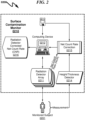
- FIG. 2 An overview of the present invention system is generally illustrated in FIG. 2 ( 0200 ) wherein a monitored subject ( 0201 ) is observed with a surface contamination monitoring system ( 0210 ) comprising a radiation detector array ( 0211 ) and a computing device ( 0212 ) (e.g., personal computer (PC) or other digital computerized calculating device) running under control of software read from a computer readable medium ( 0213 ).
- This computing device ( 0212 ) receives count rates from the radiation detector array ( 0211 ) configured to monitor surface radiation emitted from the monitored subject ( 0201 ).
- a mechanism for the detection of the height/thickness ( 0214 ) of the monitored subject ( 0201 ) is provided.
- This height/thickness information ( 0214 ) is utilized by net count rate (NCR) correction software ( 0215 ) operating under control of the computing device ( 0212 ) to generate a corrected radiation detector net count rate (CNR) display ( 0216 ) that compensates for the physical characteristics of the monitored subject ( 0201 ).
- NCR net count rate
- CNR corrected radiation detector net count rate
- FIG. 3 An overview of the present invention surface contamination monitoring method is generally illustrated by the flowchart of FIG. 3 ( 0300 ).
- the method generally involves reading inputs from a radiation detector array ( 0301 ) before and during the presence of a monitored subject, followed by computation of a corrected net count rate (CNR) that is based on net count rate (NCR) measured of the radiation detectors ( 0302 ) in conjunction with measured background radiation and a variety of monitored subject parameters ( 0310 ) such as height, thickness, etc.
- CNR corrected net count rate
- NCR net count rate
- monitored subject parameters 0310
- the CNR is compared to an alarm threshold ( 0303 ) to determine if the monitored subject is CONTAMINATED ( 0304 ) or NOT CONTAMINATED ( 0305 ).
- the alarm triggering decision ( 0303 ) may incorporate a variety of algorithms, and the measurement step ( 0301 ) may incorporate a wide variety of sensors and data acquisition procedures.
- the use of both stored site calibration factors as well as predefined site calibration factors in conjunction with site calibrators is anticipated as part of the monitored subject parameters (0310) that may be used in conjunction with this analysis.
- the height/thickness detectors ( 0214 ) may be embodied in a wide variety of forms, including but not limited to the use of the following methodologies:
- the present invention anticipates that the height and thickness measurements may be made using combinations of these technologies and that the height/thickness measurements may not necessarily use the same measurement technique.
- photosensors 0411, 0412, 0413, 0414, 0415
- detectors 0421, 0422, 0423, 0424, 0425
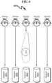
- a series of source ( 0511, 0512, 0513, 0514, 0515 ) and detector ( 0521, 0522, 0523, 0524, 0525 ) pairs are first used to determine thickness measurements in one horizontal plane of the monitored subject ( 0501 ). Subsequent to this measurement, as depicted in FIG.
- the monitored subject ( 0601 ) orientation is either changed (or equivalently an orthogonal set of sources ( 0611, 0612, 0613, 0614, 0615 ) and detectors ( 0621, 0622, 0623, 0624, 0625 )) and a detection of the orthogonal thickness of the monitored subject ( 0601 ) is determined.
- a combination of both orthogonal thickness measurements will determine the overall two-dimensional area associated with a given horizontal plane of the monitored subject ( 0501, 0601 ), and thus can be used to determine the overall volume of the monitored subject ( 0501, 0601 ) based on a given vertical measurement.
- the sensor/detector methodologies used to implement this orthogonal/quadrature thickness measurement may vary based on application context.
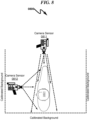
- FIG. 7 ( 0700 ) The same orthogonal/quadrature thickness measurement technique detailed in FIG. 5 ( 0500 ) - FIG. 6 ( 0600 ) may be implemented using a single video/camera image capture device as generally illustrated in FIG. 7 ( 0700 ) - FIG. 8 ( 0800 ).
- an image capture device ( 0711 ) captures an image of a monitored subject ( 0701 ) from one viewpoint against a calibrated background that enables the image capture device ( 0701 ) to properly gauge the width of the monitored subject ( 0701 ).
- FIG. 7 ( 0700 ) an image capture device ( 0711 ) captures an image of a monitored subject ( 0701 ) from one viewpoint against a calibrated background that enables the image capture device ( 0701 ) to properly gauge the width of the monitored subject ( 0701 ).
- FIG. 7 ( 0700 ) an image capture device ( 0711 ) captures an image of a monitored subject ( 0701 ) from one viewpoint against a calibrated background that enables the image capture device
- an orthogonal/quadrature image ( 0811 ) may also be captured of the monitored subject ( 0801 ) to determine the depth of the monitored subject ( 0801 ). Combining these two pieces of information enables a calculation of the body volume of the monitored subject ( 0701, 0801 ) at different height levels and thus a profile of the monitored subject ( 0701, 0801 ) can be determined at various heights.
- the calibrated background in this example can take many forms, but in many preferred embodiments a regular pattern of rectangles or calibrated rulers as generally illustrated in FIG. 13 ( 1300 ) may be used.
- FIG. 9 ( 0900 ) depicts an exemplary embodiment of a whole-body surface contamination monitoring device ( 0901 ) incorporating the inventive aspects disclosed herein as they relate to the generalized system architecture taught in FIG. 2 ( 0200, 0210 ).
- a vertical panel ( 0902 ) is added to enclose the area in which the monitored subject stands ( 0903 ) and to provide additional shielding from external radiation fields.
- This panel ( 0902 ) provides support for the overall device structure ( 0901 ) as well as the thickness sensor ( 0904 ).
- the thickness sensor (0904) utilizes photosensor device technology to determine the body thickness of the monitored subject without physically contacting the monitored subject. This can be accomplished in several ways, depending on the type of photosensor chosen.
- a first embodiment employs an infrared reflectivity device wherein the photo-detector member measures the reflectivity of light emitted from the photo-emitter member. In such a sensor, the distance between the object being sensed and the photosensor will be determined by the amount of reflectivity.
- photosensors utilize time-of-flight detection, wherein the speed of light (a known constant) may be used to determine distance to an object based on the amount of time it takes for the emitted reflected beam to be detected by the photo-detector member. Still others utilize angular detection, wherein the return angle of the reflected light determines the distance between the photosensor and the detected object. In another embodiment, an ultrasonic distance detection device that utilizes time-of-flight determinations with reflected sound as opposed to light.
- time-of-flight detection wherein the speed of light (a known constant) may be used to determine distance to an object based on the amount of time it takes for the emitted reflected beam to be detected by the photo-detector member.
- Still others utilize angular detection, wherein the return angle of the reflected light determines the distance between the photosensor and the detected object.
- an ultrasonic distance detection device that utilizes time-of-flight determinations with reflected sound as opposed to light.
- the thickness sensor ( 0904 ) is first calibrated without a monitored subject standing in the device ( 0901 ). This causes the thickness sensor ( 0904 ) control circuitry to return a value representing the distance from the sensor face to the detector array panels ( FIG. 10 ( 1008 )) .
- a monitored subject steps into the device ( 0901 ) to begin the monitoring process, they contact the radiation detector array ( FIG. 10 ( 1008 )) and the thickness sensor ( 0904 ) performs another measurement, returning a value representing the distance from the sensor face to the side of the monitored subject that is opposite the side contacting the detector array.
- the thickness sensor ( 0904 ) performs another measurement, returning a value representing the distance from the sensor face to the side of the monitored subject that is opposite the side contacting the detector array.
- a single thickness sensor ( 0904 ) is utilized at a point along the anteroposterior axis of a monitored subject of average height, slightly higher than the midpoint. In this position, the thickness sensor ( 0904 ) is exposed to the lower abdomen (or stomach area) of the monitored subject, which, on average, tends to be the thickest body portion.
- This thickness sensor may be fixed in a predetermined position within the device ( 0901 ), or may be moveable to allow the sensor to be placed in the optimum position for the given worker population that the device ( 0901 ) is intended to service.
- an array of thickness sensors ( 0904, 0905, 0906 ) is utilized to determine thickness values at different points along the anteroposterior axis of the monitored subject.
- the system may utilize an average of these multiple thickness values in subsequent correction calculations, or may apply the measured thickness value to the correction calculations for measurements obtained at each respective area of the detector array.
- a mechanical means may be utilized (for example, a tape measure or a caliper gauge) to determine the monitored subject's thickness, which may then be manually entered into the computing device.
- the height sensor ( 1007 ) is generally depicted in FIG. 10 ( 1000 ) .
- the height sensor ( 1007 ) is a multi-beam photosensor device having emitter/receiver pairs positioned such that when a monitored subject enters the device ( 1001 ), they interrupt a certain number of beams.
- the height of each of the beams above the device ( 1001 ) deck is known beforehand and entered into the height sensor control circuitry.
- the height sensor ( 1007 ) control circuitry determine the lowest beam that is unbroken (or uninterrupted) by the monitored subject, and subtract half the distance between the lowest beam that is unbroken with the highest beam that is broken. This approximate height value may then be utilized in subsequent calculations.
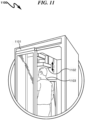
- FIG. 11 ( 1100 ) depicts an alternate means for detecting the height of a monitored subject.
- the height detector ( 1102 ) is a moveable radiation detector within the device ( 1101 ) that is positioned vertically such that it physically contacts the monitored subject's head (1103) or rests slightly above.
- the device ( 1101 ) then automatically determines the height of the monitored subject based upon the position of the height detector ( 1102 ) relative to the floor or overhead of the device ( 1101 ) . Movement of the height detector ( 1102 ) may be through manual or automatic means.
- the height sensor array may utilize the same types of reflective sensing devices as mentioned for the thickness sensor.
- an ultrasonic sensing device may rely on the time-in-flight method, or an infrared sensing device may rely on reflectivity.
- FIG. 12 ( 1200 ) depicts a preferred exemplary ionizing radiation sensor array arrangement as utilized by a preferred embodiment of the present invention.
- the detector array consists of a combination of well-known alpha/beta (gas), and gamma (scintillation) detectors.
- the gamma detector panels ( 1227, 1228, 1229 ) may be physically located behind the alpha/beta detectors ( 1201 ) - ( 1225 ) within the device ( 0901 ), but are shown in the depiction alongside the alpha/beta detector array for clarity.
- the entire detector array ( 1201 ) - ( 1225 ) consists of panels sensitive to beta and gamma radiations.
- Relevant gamma detectors for this embodiment are ( 1203 ) - ( 1217 ) .
- One of ordinary skill in the art will understand and appreciate that the operational theory and detector circuitry design for utilization of these detectors is well known in the industry and does not serve to limit the scope of the claims herein.
- a computing device accepts inputs from the detector device ( 1201 ) - ( 1229 ) control circuitry to accept detection events.
- the computing device also accepts inputs from the aforementioned height and thickness sensors, and utilizes the signals provided by each in subsequent computations using the net count rate (NCR) as it relates to the self-shielding factor and corrected net count rate (CNR).
- NCR net count rate
- CNR self-shielding factor and corrected net count rate
- GUI graphical user interface
- GUI graphical user interface
- the embodiment utilizes a single computer device, multiple such devices may be utilized in other embodiments to improve net count rate (NCR) processing speed or to provide operational redundancy.
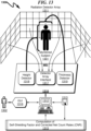
- the radiation detector array arrangements described in FIG. 12 ( 1200 ) may serve as the basis for a system/method application context as generally illustrated in FIG. 13 ( 1300 ), wherein the monitored subject ( 1301 ) is placed within a contamination monitoring system comprising the radiation detection array ( 1311 ) used to detect monitored subject ( 1 301 ) contamination in conjunction with monitored subject interface (MSI) ( 1310 ) comprising the radiation detector array interface ( 1317 ) and height detector ( 1318 ) and thickness detector ( 1319 ) .
- MSI monitored subject interface
- a computer control unit ( 1302 ) executing computer codes retrieved from a computer readable medium ( 1313 ) is used to control the data collection and provide a graphical user/alarm interface ( 1316 ) for an operator ( 1302 ) to report the results of the computation of self-shielding factors and corrected net count rates (CNR) ( 1315 ) .
- CNR corrected net count rates
- FIG. 14 depicts a method architecture flowchart indicating major data processing steps as well as data sources for those steps. As illustrated, this architectural diagram is divided into major areas involving measured quantities ( 1410 ), the methodology applied to these measured quantities ( 1420 ), temporal actions occurring during installation ( 1430 ), and temporal actions occurring during measurement of the monitored subject ( 1440 ) . Within this flow diagram the major portions of the method steps performed by several preferred embodiments in calculating the monitored-subject's corrected net count rate (NCR) are illustrated.
- NCR monitored-subject's corrected net count rate
- On-site calibration consists of obtaining measurements with the device without monitored subjects standing therein, and by obtaining measurements with a plurality of monitored subjects (also called “site calibrators”) known to be uncontaminated by radioactive materials.
- site calibrators i.e., known uncontaminated workers representing the population of radiation workers at a particular site are especially useful in calibration because such calibrators more accurately reflect the true makeup of the worker population that will be monitored. Moreover, it is best to utilize the largest number of site calibrators ( 1411 ) as possible in order to obtain the greatest amount of calibration data from which to work.
- a plurality of site calibrators ( 1411 ) are monitored to obtain self-shielding on-site count data, the site calibration factors are calculated ( 1421 ) based upon the calibrator data ( 1411 ), and the site calibration factors are stored within the system in predetermined bins for subsequent calculations as the F ca / value or factor ( 1422 ).
- the site calibrator data (1411) as depicted in FIG. 15 ( 1500 ) is initially broken-up into nine height/thickness bins ( 1531, 1532, 1533, 1534, 1535, 1536, 1537, 1538, 1539 ).
- the purpose of the bins ( 1531, 1532, 1533, 1534, 1535, 1536, 1537, 1538, 1539 ) is to provide more flexibility to adjust and modify the factory parameters depending on the on-site conditions and population. From this figure ( 1500 ), it can be seen that the thickness data ( 1510 ) has been divided into ranges of 0-25 cm ( 1511 ), 25-50 cm ( 1512 ), and 50-75 cm ( 1513 ).
- Height data ( 1520 ) has been divided into ranges of 150-167 cm ( 1521 ), 167-184 cm ( 1522 ), and 184-200 cm ( 1523 ). Thus, this creates a 3x3 matrix of nine bins total. For example, using the binning process, site calibrator data obtained from workers that are from 0-25 cm thick and from 150-167 cm tall is used to populate the first bin ( 1531 ), site calibrator data obtained from workers that are from 25-50 cm thick and from 150-167 cm tall is used to populate the second bin ( 1532 ), and so on. The bin limits are adjusted to match the actual on-site worker population such that the bins are populated uniformly during calibration and operation.
- the calibrator enters the machine and assumes position 1 (anterior surface toward detector panels) and the first measurement is obtained and a F cal factor for position 1 is computed.
- the calibrator turns to assume position 2 (posterior surface toward the detector panels) and the second measurement is obtained and a F cal factor for position 2 is computed. These factors are then retained within the appropriate bin. As additional site calibrators are measured, the additional and existing F ca / factors are averaged for the particular bin.
- empty bins 1531, 1532, 1533, 1534, 1536, 1537, 1538, 1539 receive a global average F ca / factor.
- empty bins with populated neighboring bins are averaged together and the resulting average is placed within the empty bin.
- the first bin ( 1531 ) receives the global average F cal factor.
- this global F ca / factor is averaged with the F ca / factor from neighboring bin 2 ( 1532 ) and bin 4 ( 1534 ), and not bin 5 ( 1535 ).
- This new average F ca / factor is then retained within bin 1 ( 1531 ) for subsequent measurements.
- the diagonal bin (bin 5 ( 1535 )) is also averaged as a contributing neighbor.
- the present embodiment utilizes an F ca / factor for position 1 and an F cal factor for position 2 within each bin, whereas in another embodiment a single F ca / factor might be used for both positions. It should be noted in the example of FIG. 15 ( 1500 ) that the F ca / factors are all identical because only a single calibrator has been measured.
- the F ca / factor depends on the attenuation factor ( F att ) and the measured self-shielding factor ( SSF measured ) for the site calibrators as well as certain predefined factory calibration factors.
- the measured count rate ( R m ) is the count rate measured with the site calibrator in the contamination monitoring device ( 0210 ).
- factory calibration data (C factors) (1423) that are predefined based upon known and previously measured (empirical value) characteristics of the detectors that are utilized within the device, as well as the control circuitry, geometry of the array, relative location of the detector panels, and the like.
- the predefined factory calibration factors ( 1423 ) for the present embodiment are obtained empirically based upon a large data set of uncontaminated calibrators measured during development of the system.
- the actual factory calibration factors are dependent upon the physical hardware and will vary from implementation to implementation, and will know how to obtain such factors for the given system hardware implementation.
- the calibration factors ( 1423 ) are represented by ⁇ , a, b, c, d, and h o for specific zones.
- Each zone may consist of a single numbered detector from the overall array as depicted in FIG. 12 ( 1200 ), or may consist of a plurality of neighboring detectors.
- Zone 73 on the tables illustrated in FIG. 17 ( 1700 ) and FIG. 19 ( 1900 ) may represent a combination of several neighboring detectors.
- the stored site calibration factors ( 1422 ) and predefined calibration factors ( 1423 ) have been obtained as previously described.
- the unoccupied background count rate (factor BR) ( 1412 ) is obtained before a monitored subject enters the monitoring device for measurement.
- a monitored subject then enters the monitoring device and the monitored subject's height (factor H) ( 1413 ) and thickness (factor T) (1414) values are obtained in a manner as previously described.
- the height (H) ( 1413 ) and thickness (T) ( 1414 ) values are then utilized by the computing device to calculate the self-shielding factor (SF) ( 1424 ), which is a factor of F cal , C, H, and T as shown below in Equation (4) and Equation (5):
- SF P 1 1 ⁇ w ⁇ F cal P 1 ⁇ F att 1 ⁇ ⁇ ⁇ e ⁇ a ⁇ t
- P 2 1 ⁇ w ⁇ F cal P 2 ⁇ F att 1 ⁇ ⁇ ⁇ e ⁇ a ⁇ t
- Equation (4) reflects the calculation with the monitored subject in position 1 within the monitoring device while Equation (5) reflects the calculation with the monitored subject in position 2.
- the attenuation factor is position independent given that it is based on factory calibration data that is determined by the hardware characteristics.
- the "w" variable is a monitored subject defined weighting variable that allows the monitoring device operator to alter the shielding factors globally, with a single value, with a range typically between 0 and 1. This "w" variable is also considered part of the calibration factors, C ( 1423 ).
- the sum zone self-shielding factor SF i is a factor of the corrected count rate divided by the measured background count rate (Rb).
- SF 27 + 28 SSF 27 ⁇ R b 27 + SSF 28 ⁇ R b 28 R b 27 + R b 28
- Additional detector panels may be added to the sum zone as desired, which increases the overall sensitivity of the resultant sum zone detector as illustrated by the above equations.
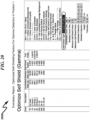
- An exemplary report of self-shielding factors as calculated using these equations for individual and sum zone areas is generally illustrated in FIG. 20 ( 2000 ).
- this value is combined with the measured background count rate ( 1412 ) to compute a corrected background count rate (BR*) ( 1425 ).
- the monitored subject is then monitored to obtain a subject net count rate (NCR) ( 1415 ), which is then combined with the corrected background count rate ( 1425 ) to calculate a corrected net count rate (CNR) ( 1426 ), which reflects the actual contamination present on the monitored subject. If the corrected net count rate (CNR) is above a preset alarm threshold ( 1427 ), the monitored subject is considered contaminated ( 1428 ) and an alarm is registered. However, if the corrected net count rate (CNR) is not above the alarm threshold trip point, the monitored subject is considered clean ( 1429 ) and no alarm is registered.
- a Contamination Check Results report file may optionally be created automatically after every contamination monitoring cycle as is generally illustrated in FIG. 21 ( 2100 ), including both positions for 2-Step monitors, during normal operation (occupant check), detector/zone contamination checks (contaminated results only), and alarm tests.
- the Contamination Check Results report may provide the raw data used in making a "Clean” or "Contaminated” decision, including detector counts and alarm trip points for every detection zone, including sum zones (pairs, triplets, quads and "All” as applicable). This report may be used to facilitate a retrospective audit of "Clean” and "Contaminated” decisions.
- the contamination monitor may also perform a Detector Contamination Check.
- a Contamination Detector Check Results report may be created if the contamination monitor result is "Contaminated”.
- All Contamination Check Results files may optionally be automatically transferred to the central history computer or the mapped network drive if the system is as such.
- the present invention may incorporate a monitoring algorithm using an optimization strategy for the selection of alarm set points and counting times.
- Each time the contamination monitor is used it may calculate the minimum counting time required to provide an accurate decision for monitored subjects who have little or no contamination and for occupants who are clearly contaminated. For those rare cases when monitored subject has contamination close to the alarm set point, an extended counting time may be required to resolve the clean/contaminated decision.
- the main consideration in determining the optimum counting time is the potential for error caused by statistical fluctuations in the measured count rates. Appropriate calculations may be performed to obtain accurate clean/contaminated decisions within application specific (or user defined) reliability parameters.
- the greatest component of statistical error is usually in the gross count rate due to the relatively short counting time.
- the error in the background average rate is usually less significant due to the longer averaging period. However, this might not be the case in unusually high background conditions or if the background averaging period is short as in following a step change in background. This phenomenon is generally illustrated by the background radiation curves depicted in FIG. 22 ( 2200 ).
- the present invention may consider the statistical error in the background average during alarm set point and counting time calculations to adjust for these factors.
- the Used Trip Point is the value that is compared with the compensated net count rate (CNR) to make the Clean / Contaminated decision. It can be the Lowest Level Of Detection (LLD), the Contaminated Trip Point (CTP), or the Alarm Trip Point (ATP), depending on the circumstances.
- LLD Lowest Level Of Detection
- CTP Contaminated Trip Point
- ATP Alarm Trip Point
- LLD Lowest Level of Detection
- R b the effective average background count rate (for the individual zone), i.e. the average background count rate R B multiplied by the Self Shield Factor
- T m the monitoring time
- T b the time over which the background count rate is averaged ( Background Average Period default is typically 300s).
- the Self Shield Factor is described elsewhere herein.
- K ⁇ is a statistical term related to the false alarm rate.
- the Contaminated Trip Point is the count rate above background at which the detection zone is considered to be definitely measuring contamination in excess of the Alarm Activity (release limit), even allowing for statistical counting error.
- the difference between CTP and ALS represents the statistical error in ALS and in the background average R b .
- K ⁇ 1 is a statistical term related to the confidence of alarm.
- the Alarm Trip Point is the count rate above background at which the detection zone is considered to be possibly measuring contamination in excess of the Alarm Activity (release limit). Conversely, a count rate below the ATP is considered definitely clean, even allowing for statistical counting error.
- the ATP is the Alarm Level Set point (ALS) minus the statistical error in the ALS and background average values.
- ALS Alarm Level Set point
- the Used Trip Point is the higher of LLD and ATP. This can result in false "Contaminated” results when the count rate is between the ATP and the CTP.
- UTP Used Trip Point
- the UTP When Extend Count If Contaminated is enabled, then the UTP is the higher of LLD and CTP. A net rate between ATP and CTP will extend the count time by a user defined value. Following the extended count, the UTP reverts to the higher of LLD and ATP calculated for the total (normal plus extended) counting time, which is higher than the corresponding values at the end of the initial count time, because the error term is smaller. Note that if any zone(s) registers definitely contaminated (above the CTP) then the unit will alarm at the end of the initial (i.e. not extended) counting time and the UTP for the remaining zones reverts to the higher of LLD and ATP.
- FIG. 23 ( 2300 ) illustrates the relationship between CTP, ATP, ALS, LLD and average background count rate R b . Notice how the spread between ATP, ALS and CTP decreases when the Count Time is extended.
- T m s 1 2 X 0 2 ⁇ 4 Y 0 ⁇ X 0
- the equation above is solved for every detection zone (singles, pairs, triplets, quads and all and quads) in the system.
- the zone that requires the longest counting time (having allowed for counting feet in two steps, if enabled) becomes the controlling zone for determining the system counting time.
- the minimum monitoring time ( T m ) may be reported as 0.01s even if the calculated value is less than 0.01s.
- the actual counting time in effect may be the time required by the controlling zone, rounded up to the next whole integer of seconds.
- a Maximum Monitor Time user parameter may be used such that if this parameter is less than the count time needed to meet the alarm accuracy (that is, less than T m ), then the LLD may be used for the trip point in place of the ATP. This substitution may prevent abnormal false alarm rates at the expense of decreased alarm sensitivity.
- a status screen indicator may be presented in this instance to indicate that the unit is operating with reduced alarm sensitivity and that the monitor is more likely to indicate a Clean result for contamination close to the alarm release limit. There may only be 1 or 2 detection zones at the LLD, while the remaining zones may be still at the ATP, i.e. providing full alarm sensitivity in those regions.
- T m s K ⁇ ⁇ R b cps + K ⁇ ⁇ ALS cps + R b cps ALS cps 2
- the equation above calculates a count time without the T b term and may be used to check the effect of the Background Average Period ( T b ) term.
- the K ⁇ (K Alpha) term is a statistical term related to the false alarm rate (FAR) due to background radiation.
- the K Alpha term determines the Lowest Level of Detection (LLD) for the contamination monitor given the acceptable false alarm rate. It is the system false alarm rate that is important, as opposed to that for individual detection zones.
- the monitoring time for the system is controlled by the "worst-case" zone and is dependent on the background count rate, the zone efficiency, etc. As the worst-case zone sets the counting time, all other zones are forced to count longer than needed and therefore have improved statistical data for making a decision, i.e. they will have a lower FAR.
- the foot detectors are frequently the "worst-case" detectors, since they have lower efficiency. Other detectors may count longer than they need to, and thus have a reduced probability of false alarming.
- the K Beta terms determine the confidence that the system will alarm for a true "contaminated” condition. This is the statistical confidence that the alarm trip level will be exceeded by the net count rate for the detection zone and is based on a statistical calculation for a "2-tail” Poisson distribution.
- the default K Beta is typically set to 2.00 (95.45%).
- An exemplary table correlating alarm confidence to the K Beta term is provided below: Alarm Confidence (2 tail) in % K Beta 75 1.151 80 1.282 85 1.440 90 1.645 95 1.960 96 2.054 97 2.170 98 2.326 99 2.575
- FIG. 24 As generally illustrated in FIG. 24 ( 2400 ) , operating under control of a computerized computing device, the flow depicted in figure 24 comprises the steps of:
- the present invention preferred system embodiment anticipates a wide variety of variations in the basic theme of construction, but can be generalized as a surface contamination monitoring system as claimed in claim 1.
- the present invention preferred exemplary method embodiment anticipates a wide variety of variations in the basic theme of implementation, but can be generalized as a surface contamination monitoring method operating under control of a computerized computing device, according to claim 12.
- the present invention anticipates that the monitored subject may be weighed (either manually or by automatic means) in some preferred invention embodiments to permit the thickness/height measurements performed herein to accommodate accurate density distributions within the body of the measured subject and therefore permit a more accurate corrected net count rate (CNR) determination to be performed.
- CNR net count rate
- the present invention anticipates a wide variety of variations in the basic theme of construction.
- the examples presented previously do not represent the entire scope of possible usages. They are meant to cite a few of the almost limitless possibilities.
- the present invention may be implemented as a computer program product for use with a computerized computing system.
- programs defining the functions defined by the present invention can be written in any appropriate programming language and delivered to a computer in many forms, including but not limited to: (a) information permanently stored on non-writeable storage media (e.g., read-only memory devices such as ROMs or CD-ROM disks); (b) information alterably stored on writeable storage media (e.g., floppy disks and hard drives); and/or (c) information conveyed to a computer through communication media, such as a local area network, a telephone network, or a public network such as the Internet.
- non-writeable storage media e.g., read-only memory devices such as ROMs or CD-ROM disks
- writeable storage media e.g., floppy disks and hard drives
- information conveyed to a computer through communication media such as a local area network, a telephone network, or a public network such as the Internet.
- the present invention system embodiments can incorporate a variety of computer readable media that comprise computer usable media having computer readable code means embodied therein.
- One skilled in the art will recognize that the software associated with the various processes described herein can be embodied in a wide variety of computer accessible media from which the software is loaded and activated. Pursuant to In re Beauregard, 35 USPQ2d 1383 ( U.S. Patent 5,710,578 ), the present invention anticipates and includes this type of computer readable media even though they do not form part of the claimed invention.
- a surface contamination monitoring system/method configured to correct the detected the radioactive net count rate (NCR) value of a whole-body surface contamination monitoring device based on monitored subject height and thickness values has been disclosed.
- the net count rate (NCR) is corrected based on the determined height and thickness values of the monitored subject as applied to site calibration factor data and self-shielding factor data to produce a corrected net count rate (CNR). If the corrected net count rate (CNR) registers above a preset alarm threshold, the monitored subject is considered contaminated and an appropriate alarm is registered.
Landscapes
- Health & Medical Sciences (AREA)
- Physics & Mathematics (AREA)
- Life Sciences & Earth Sciences (AREA)
- Spectroscopy & Molecular Physics (AREA)
- Molecular Biology (AREA)
- High Energy & Nuclear Physics (AREA)
- General Physics & Mathematics (AREA)
- Biomedical Technology (AREA)
- Optics & Photonics (AREA)
- Nuclear Medicine, Radiotherapy & Molecular Imaging (AREA)
- Medical Informatics (AREA)
- General Health & Medical Sciences (AREA)
- Engineering & Computer Science (AREA)
- Measurement Of Radiation (AREA)
Description
- The present invention generally relates to systems and methods for radiation detection in applications of surface contamination monitoring. Without limitation, this may include systems/methods for improving the accuracy of radiation contamination monitors used to determine surface contamination on monitored subjects, such as in the application of whole-body contamination monitoring of the body of a worker in an industrial environment.
- Given the potentially harmful physiological effects from exposure to radiation, it is important to regularly monitor radiation workers, and other workers with potential whole-body exposure to radioactive materials, to assess potential contamination that might be present on or within the worker's body. As generally depicted in
FIG. 1 (0100), whole-body ionizing radiation-monitoring devices for use with monitored subjects (0101) have been developed to automate and to improve the efficiency and effectiveness of this monitoring process. - As generally depicted in
FIG. 1 (0100), a typical prior art monitoring portal (0110) utilizes an array of radiation detectors (0111), a number of which detect gamma radiation. The array (0111) allows a monitored subject (radiation worker) (0101) to enter the device and stand with one side of the worker's body positioned before the detector array (0111). An arm, side leg, and hand monitoring array (0112) is also present in the depiction. As shown, the monitored subject (0101) is facing the detector array (0111), with their right hand and arm inserted in the array (0112). Detectors (0113) on the base of the monitoring portal (0110) detect contamination that may be present on the monitored subject's (0101) feet. Thus, the monitored subject's (0101) anterior surface, right arm, right outside leg, and feet are being monitored for surface contamination. Once this anterior surface monitoring is complete, the monitored subject (0101) turns with their posterior surface against the detector array (0111), with their left hand and arm inserted in the array (0112). Once the posterior surface of the monitored subject (0101) has been surveyed, the measurement data is processed by an automated computing device, which logs the measurements and signals a contamination alarm if necessary. - On-site calibration of such detection devices is crucial to the accuracy of its radiation measurements. As is commonly understood, gamma-ray background radiation is always present at levels that vary from physical location to location. To compensate for this background radiation variability, an on-site calibration routine utilizing one or more monitored subjects (who are known not to be contaminated) is typically performed to determine the existing background radiation properties and their effects on occupant self-shielding. The predetermined calibration factors to calculate the effects caused by the fact that the monitored subject's body has a shielding effect on the detector array (0111) may not fully describe the self-shielding on-site.
- When standing in front of the detector array (0111), the monitored subject's body (0101) will absorb and/or scatter a certain amount of the background gamma radiation. This causes the resulting measured radiation net count rate (NCR) value to be different than the actual count rate (ACR) present on the monitored subject's body, because the background radiation (though no longer being detected at the same rate as before the monitored subject entered the device) is still being deducted from the measured counts. Thus, the sensitivity and accuracy of the surface contamination monitoring device is negatively impacted by this effect.
- A common method currently employed in an attempt to deal with this problem is to apply a single correction factor to the measurement that compensates for this whole-body shielding effect upon the detectors. Essentially, a group of monitored subjects who are known not to be contaminated is surveyed and an average "standard" monitored subject profile is obtained. This "standard" monitored subject profile is intended to compensate for the average shielding effect that a body has on the measured background radiation. Thus, a single correction factor is applied to the measured radiation net count rate determinations. While this is an improvement over previous methods of measured radiation count rate determinations, it still does not account for the effects of varying body shapes and sizes. For example, a monitored subject with a slight frame (less shielding than average) will experience a measured radiation net count rate (NCR) greater than the actual count rate (ACR) while a monitored subject with a heavier frame (more shielding than average) will experience a measured radiation net count rate (NCR) less than the actual count rate (ACR).
- Moreover, the average "standard" monitored subject profile does not compensate for the effects that various body heights and thicknesses have on the sensitivity and accuracy of the various sections of the detector array. For example, to increase sensitivity in the detectors, various detectors within the array will be grouped together to form a larger effective scintillating volume. Therefore, a monitored subject that is shorter than average or that has a slight frame will leave certain detector groupings exposed to (or unshielded from) the background counts. Thus, while the average "standard" monitored subject profile compensation assumes that these certain detector groupings should be experiencing some shielding, the resulting net count rate (NCR) will be greater than actual. Conversely, a monitored subject that is much taller than average or that has a much heavier frame will provide more shielding than average in a greater number of detector groupings. Because shielding for this monitored subject is more than average, the resulting measured radiation net count rate (NCR) will be less than the actual count rate (ACR).
- Further still, this average "standard" monitored subject profile does not account for varying thickness of individual monitored subjects. For example, a monitored subject with an athletic build (small waist and midsection (gut) area, but large upper body) will provide more shielding to portions of the detector array near the chest area as opposed to those near the waist area. Thus, the portions of the detector array near the chest area, in reality, require a different correction factor than those near the monitored subject's waist. This requirement is reversed in the situation with a monitored subject having an excessively large midsection and relatively small upper body. Accordingly, the current "one-size-fits-all" approach does not adequately compensate for varying monitored subject bodies.
- Still others have attempted to compensate for this shielding effect by considering the monitored subject's body weight in determining a correction factor. While this may give some indication as to the monitored subject's density, it is no more accurate because it fails to consider the overall density distribution. Different types of tissue (muscle, adipose, etc.) have different densities and elemental compositions, affecting their absorption and scattering properties. Again, a monitored subject with an athletic build may carry all of his or her weight in the chest region, yet would weigh the same as (or even more than) an obese monitored subject carrying all of his or her weight in the midsection (gut) area. Moreover, a 183 cm tall individual that weighs 80 kg will have a different density distribution than a 152 cm tall individual of the same weight. Again, the same poorly-corrected-for shielding problems occur. What is needed is a more accurate method of correcting for the self-shielding effect that varying body sizes have upon whole-body detector arrays.
- The prior art as detailed above suffers from the following deficiencies:
- Prior art surface contamination monitoring systems fail to accurately compensate NCR for environmental radiation factors.
- Prior art surface contamination monitoring systems fail to accurately compensate NCR variations in body size and height.
- Prior art surface contamination monitoring systems fail to accurately compensate NCR variations in body type and composition.
- Prior art surface contamination monitoring systems have no means to automatically incorporate variations in the measurement subject into the NCR compensation.
- Prior art surface contamination monitoring systems utilize "one size fits all" NCR compensation techniques which do not accurately produce ACR compensated values.
- While some of the prior art may teach some solutions to several of these problems, the core issue of improving the accuracy of surface contamination monitoring systems has not been solved by the prior art.
- The document: The Determination of Total-body Potassium using a Whole-body Monitor. T.Hawkins, A.W.Goode, Phys.Med.Biol.. 1976, Vo1.21, No.2, pp.293-297, e.g. teaches a whole body monitoring system which determines a calibration factor for an individual taking into account physical characteristics, such as weight and height.
- A detailed study was made of the influence of the body habitus on background counting rates for measuring total body potassium content. The calibration factor represents the ratio of K-42 counts per minute per pCi of a phantom to K-42 counts per minute per pCi of a subject and was approximated using a linear equation taking into account the height and weight.
-
JPH0392788 - Accordingly, the objectives of the present invention are (among others) to circumvent the deficiencies in the prior art. In the context of a surface contamination monitoring system according to
claim 1 and a method according toclaim 12, the objectives further are: - (1) Provide for surface contamination monitoring system and method that automatically compensates NCR for self-shielding effects in the monitored subject.
- (2) Provide for surface contamination monitoring system and method that automatically compensates NCR for body variations in the monitored subject.
- (3) Provide for a surface contamination monitoring system and method that automatically determines the height and thickness of the monitored subject.
- (4) Provide for a surface contamination monitoring system and method that permits shielding of the monitored subject during the contamination monitoring evaluation.
- (5) Provide for a surface contamination monitoring system and method that permits the use of arrayed gamma ray detectors to perform monitored subject contamination detection.
- (6) Provide for a surface contamination monitoring system and method that permits radiation detectors within a radiation detector array to be combined to form summing zones that may be used to improve overall contamination monitoring accuracy.
- (7) Provide for a surface contamination monitoring system and method that permits monitored subject contamination examination without subject contact.
- (8) Provide for a surface contamination monitoring system and method that permits a more accurate determination of whether a monitored subject is in fact been radiation contaminated.
- (9) Provide for a surface contamination monitoring system and method that incorporates an arbitrary number of on-site calibrators to accurately characterize the local background and monitored subject (worker) population.
- While these objectives should not be understood to limit the teachings of the present invention, in general these objectives are achieved in part or in whole by the disclosed invention that is discussed in the following sections. One skilled in the art will no doubt be able to select aspects of the present invention as disclosed to affect any combination of the objectives described above.
- One embodiment disclosed herein is a whole-body surface contamination monitoring system, as claimed in
claim 1. - Further embodiments are detailed in the dependent claims.
- The present invention further details a surface contamination monitoring method as claimed in
claim 12. - The method (300) is generally illustrated in
Figure 3 . - The overall scope of the present invention is defined by the appended claims.
- For a fuller understanding of the advantages provided by the invention, reference should be made to the following detailed description together with the accompanying drawings wherein:
-
FIG. 1 illustrates a typical prior art whole-body surface contamination radiation monitoring device and depicts a monitored subject (radiation worker) standing therein; -
FIG. 2 illustrates a system block overview diagram describing a presently preferred embodiment of the present invention; -
FIG. 3 illustrates an exemplary flowchart describing a presently preferred method embodiment; -
FIG. 4 illustrates a multi-beam photosensor height detection methodology useful in some preferred embodiments; -
FIG. 5 illustrates a multi-beam orthogonal/quadrature photosensor thickness detection methodology useful in some preferred embodiments; -
FIG. 6 illustrates a multi-beam orthogonal/quadrature photosensor thickness detection methodology useful in some preferred embodiments; -
FIG. 7 illustrates a single-image orthogonal/quadrature video/camera thickness detection methodology useful in some preferred embodiments; -
FIG. 8 illustrates a multi-image orthogonal/quadrature video/camera thickness detection methodology useful in some preferred embodiments; -
FIG. 9 illustrates a depiction of a portion of an preferred embodiment of the present invention, drawing the reader's attention to portions of an automatic thickness sensing device; -
FIG. 10 illustrates a depiction of a portion of an preferred embodiment of the present invention, drawing the reader's attention to portions of an automatic height sensing device; -
FIG. 11 illustrates a depiction of an preferred alternate means for automatically determining the height of a monitored subject (radiation worker); -
FIG. 12 illustrates a depiction of an ionizing radiation sensor array arrangement as utilized in a preferred system embodiment of the present invention; -
FIG. 13 illustrates a data flow diagram describing information flow within a presently preferred embodiment of the present invention; -
FIG. 14 illustrates a flowchart representing major portions of the method steps performed by the embodiment; -
FIG. 15 illustrates anthropometric correction F ca/ tables as generated by a preferred embodiment of the present invention; -
FIG. 16 illustrates exemplary default gamma detector values forpositions -
FIG. 17 illustrates exemplary default PGB detector values forpositions -
FIG. 18 illustrates exemplary anthropometric correction values and their associated position/zone affiliations; -
FIG. 19 illustrates exemplary anthropometric correction values and their associated position/zone affiliations; -
FIG. 20 illustrates an exemplary optimized self-shielding factors for gamma detectors report; -
FIG. 21 illustrates an exemplary contamination monitoring report printout; -
FIG. 22 illustrates an exemplary background radiation trend graph depicting background radiation changing over time; -
FIG. 23 illustrates an exemplary graph of Extended Counts Under Conditions Of Potential Contamination and relates various parameters associated with alarm thresholds. -
FIG. 24 illustrates a detailed method flowchart associated with some preferred embodiments of the present invention; - While the invention can be carried out in different forms, a preferred embodiment is shown in the drawings and will be described in detail herein.
- The numerous innovative teachings of the present application will be described with particular reference to the presently preferred embodiment, wherein these innovative teachings are advantageously applied to the particular problems of a SURFACE CONTAMINATION MONITORING SYSTEM AND METHOD.
- In general, statements made in the specification of the present application do not necessarily limit any of the claimed embodiments.
- Moreover, some statements may apply to some inventive features but not to others.
- The present invention may make use of a wide variety of computing devices in its general theme of construction. As used herein "computing device" means any computer processing device capable of executing program instructions stored on a computer readable medium. While Personal Computer (PC) construction may be optimal in many circumstances, the present invention is not limited to this particular form of construction and the term "computing device" and "PC" should be given their broadest possible definitions in this context.
- While various preferred embodiments of the present invention presented herein may utilize a wide variety of photosensors and/or ultrasonic sensors and/or mechanical contact sensors for the determination of height and thickness values for a monitored subject, the present invention is not limited to these types of sensors for the determination of these values.
- While various preferred embodiments of the present invention presented herein may utilize a wide variety of sensors for the determination of height and thickness values for a monitored subject, the term "sensor" or "sensor device" should be broadly construed to incorporate the use of video and still camera apparatus that may be used to perform equivalent orthogonal body height/thickness analysis of the monitored subject. Some exemplary sensors anticipated for use in various embodiments of the present invention include but are not limited to: photosensor; infrared reflectivity photosensor; time-of-flight photosensor; angular detection photosensor; multi-beam photosensor; orthogonal array photosensor; ultrasonic sensor; and mechanical contact sensor.
- While the present invention may be advantageously applied to contexts in which gamma radiation is the object of detection by the surface contamination monitoring system/method, the present invention is not limited to this type of radiation detection.
- Within this document the term "monitored subject" will be generally be used to describe an individual who is the subject of radiation monitoring within the context of a whole-body surface contamination monitoring system. This term should be deemed synonymous with a wide variety of other terms/phrases in this context (user, worker, radiation worker, etc.) to mean the object of the monitoring system/method. This term may also include the "body" of the monitored subject, although the term "monitored subject" shall be broadly construed to incorporate both the subject body and any clothing or other garments and as such should be broadly construed in this application context.
- While the present invention may be advantageously applied in many application contexts to a whole-body surface contamination monitoring system/method, the present invention is not strictly limited to whole-body surface contamination monitoring, and may be applied to portions of the monitored subject.
- An overview of the present invention system is generally illustrated in
FIG. 2 (0200) wherein a monitored subject (0201) is observed with a surface contamination monitoring system (0210) comprising a radiation detector array (0211) and a computing device (0212) (e.g., personal computer (PC) or other digital computerized calculating device) running under control of software read from a computer readable medium (0213). This computing device (0212) receives count rates from the radiation detector array (0211) configured to monitor surface radiation emitted from the monitored subject (0201). A mechanism for the detection of the height/thickness (0214) of the monitored subject (0201) is provided. This height/thickness information (0214) is utilized by net count rate (NCR) correction software (0215) operating under control of the computing device (0212) to generate a corrected radiation detector net count rate (CNR) display (0216) that compensates for the physical characteristics of the monitored subject (0201). - An overview of the present invention surface contamination monitoring method is generally illustrated by the flowchart of
FIG. 3 (0300). Here the method generally involves reading inputs from a radiation detector array (0301) before and during the presence of a monitored subject, followed by computation of a corrected net count rate (CNR) that is based on net count rate (NCR) measured of the radiation detectors (0302) in conjunction with measured background radiation and a variety of monitored subject parameters (0310) such as height, thickness, etc. Once the CNR has been calculated, it is compared to an alarm threshold (0303) to determine if the monitored subject is CONTAMINATED (0304) or NOT CONTAMINATED (0305). Within this methodology context, the alarm triggering decision (0303) may incorporate a variety of algorithms, and the measurement step (0301) may incorporate a wide variety of sensors and data acquisition procedures. The use of both stored site calibration factors as well as predefined site calibration factors in conjunction with site calibrators is anticipated as part of the monitored subject parameters (0310) that may be used in conjunction with this analysis. - While the present invention may incorporate many features as described herein, several are thought of as optimal and are as follows:
- Standard features may include a color XVGA LCD display that indicate and prompt for monitoring procedures and proper positioning of the monitored subject, and for detected contamination, which detector is above the set alarm level. System setup (counting times, alarm levels or release limits, calibration, and high voltage and discriminator settings, etc.) may be accomplished through a PC alphanumeric keyboard/pointing device combo. Results of the automatic system self-diagnosis may be sent to a remote location.
- The software described herein may detect changes in background during monitoring and force recount to avoid either false alarms or false negative results. Measurements in this context are typically fast and accurate, which is particularly important with changing backgrounds. An automatic high background warning and return to service feature may be incorporated, as well as automatic return to service following decontamination of a contaminated detector.
- Sensors placed strategically on the monitor sense the approach of a monitored subject, stop the current background update to eliminate any user-induced effect, establish the user's presence on the monitor platform (the "user" becomes the "occupant"), and senses the correct positioning of the monitored subject's body. Occupants may be clearly instructed about the monitoring sequence both by graphics on the display screen and by voice instruction.
- When personnel monitoring is completed, the occupant may receive one of three messages, both audibly and visually: "CLEAN", "CONTAMINATED", or "TURN" (for 2-step contamination monitoring only).
- If any alarm level has been exceeded, the "CONTAMINATED" message given at the completion of monitoring may also provide a display of all detectors, with alarming detectors shown in flashing red. The option of displaying Gross Rate, Net Rate or Net Activity for each alarming detector may also be made available. A red LED beside the alarming detector(s) may indicate the contaminated region.
- The contamination monitor may be equipped with an Ethernet connector for networking capability. Control software may use this feature to permit monitoring and displaying the operational status of multiple contamination monitor units on a Central Monitoring computer. Data files, which include configuration settings as well as calibration, maintenance and results files, may be sent to a network computer for archiving or for analysis. This file transfer operation may be done automatically at a preset time every day or when requested by a system operator. Automatic transfer of monitor status and history files to a central computer or network drive may also be configured.
- A Contamination Check Results report file can be created automatically after every monitoring cycle, including both positions for 2-Step monitors, during normal operation (occupant check), detector/zone contamination checks (contaminated results only), and alarm tests. The Contamination Check Results report provides all the raw data used in making a "Clean" or "Contaminated" decision, including detector counts and alarm trip points for every detection zone, including sum zones (pairs, triplets, quads and "All" as applicable). It can be used to facilitate a retrospective audit of "Clean" and "Contaminated" decisions.
- If Extended Counting Time was used in making the clean/contaminated decision, then a Pre-Extend Results file containing the results for the initial counting period may optionally be created.
- Following a user-contaminated decision, the monitor may perform a Detector Contamination Check (on page 74).
- All Contamination Check Results files may be automatically transferred to the central history computer or the mapped network drive.
- One skilled in the art will recognize that these illustrated system features are only exemplary of those possible using the teachings of the present invention.
- The height/thickness detectors (0214) may be embodied in a wide variety of forms, including but not limited to the use of the following methodologies:
- photosensor;
- infrared reflectivity photosensor;
- time-of-flight photosensor;
- angular detection photosensor;
- multi-beam photosensor;
- orthogonal (quadrature) array photosensor;
- video/still camera CCD sensor;
- ultrasonic sensor; and
- mechanical contact sensor.
- The present invention anticipates that the height and thickness measurements may be made using combinations of these technologies and that the height/thickness measurements may not necessarily use the same measurement technique.
- As generally depicted in
FIG. 4 (0400), photosensors (0411, 0412, 0413, 0414, 0415) or similar sources may be used in conjunction with corresponding detectors (0421, 0422, 0423, 0424, 0425) to determine the height of the monitored subject (0401). This is just one anticipated methodology of determining the monitored subject (0401) height. - A similar technique to that used as depicted in
FIG. 5 (0500) andFIG. 6 (0600) to implement thickness measurements using orthogonal thickness measurements. A series of source (0511, 0512, 0513, 0514, 0515) and detector (0521, 0522, 0523, 0524, 0525) pairs are first used to determine thickness measurements in one horizontal plane of the monitored subject (0501). Subsequent to this measurement, as depicted inFIG. 6 (0600), the monitored subject (0601) orientation is either changed (or equivalently an orthogonal set of sources (0611, 0612, 0613, 0614, 0615) and detectors (0621, 0622, 0623, 0624, 0625)) and a detection of the orthogonal thickness of the monitored subject (0601) is determined. A combination of both orthogonal thickness measurements will determine the overall two-dimensional area associated with a given horizontal plane of the monitored subject (0501, 0601), and thus can be used to determine the overall volume of the monitored subject (0501, 0601) based on a given vertical measurement. As generally discussed below, the sensor/detector methodologies used to implement this orthogonal/quadrature thickness measurement may vary based on application context. - The same orthogonal/quadrature thickness measurement technique detailed in
FIG. 5 (0500) -FIG. 6 (0600) may be implemented using a single video/camera image capture device as generally illustrated inFIG. 7 (0700) -FIG. 8 (0800). As generally depicted inFIG. 7 (0700), in this scenario an image capture device (0711) captures an image of a monitored subject (0701) from one viewpoint against a calibrated background that enables the image capture device (0701) to properly gauge the width of the monitored subject (0701). As depicted inFIG. 8 (0800), an orthogonal/quadrature image (0811) may also be captured of the monitored subject (0801) to determine the depth of the monitored subject (0801). Combining these two pieces of information enables a calculation of the body volume of the monitored subject (0701, 0801) at different height levels and thus a profile of the monitored subject (0701, 0801) can be determined at various heights. - The calibrated background in this example can take many forms, but in many preferred embodiments a regular pattern of rectangles or calibrated rulers as generally illustrated in
FIG. 13 (1300) may be used. -
FIG. 9 (0900) depicts an exemplary embodiment of a whole-body surface contamination monitoring device (0901) incorporating the inventive aspects disclosed herein as they relate to the generalized system architecture taught inFIG. 2 (0200, 0210). As can be seen inFIG. 9 (0900), a vertical panel (0902) is added to enclose the area in which the monitored subject stands (0903) and to provide additional shielding from external radiation fields. This panel (0902) provides support for the overall device structure (0901) as well as the thickness sensor (0904). - In a presently preferred exemplary embodiment as generally illustrated in
FIG. 9 (0900), the thickness sensor (0904) utilizes photosensor device technology to determine the body thickness of the monitored subject without physically contacting the monitored subject. This can be accomplished in several ways, depending on the type of photosensor chosen. For example, a first embodiment employs an infrared reflectivity device wherein the photo-detector member measures the reflectivity of light emitted from the photo-emitter member. In such a sensor, the distance between the object being sensed and the photosensor will be determined by the amount of reflectivity. Other photosensors utilize time-of-flight detection, wherein the speed of light (a known constant) may be used to determine distance to an object based on the amount of time it takes for the emitted reflected beam to be detected by the photo-detector member. Still others utilize angular detection, wherein the return angle of the reflected light determines the distance between the photosensor and the detected object. In another embodiment, an ultrasonic distance detection device that utilizes time-of-flight determinations with reflected sound as opposed to light. One of ordinary skill in the art will understand and appreciate that the operational theory and control design of these and other similar distance determination means is well known in the industry and does not serve to limit the scope of the claims herein. - The thickness sensor (0904) is first calibrated without a monitored subject standing in the device (0901). This causes the thickness sensor (0904) control circuitry to return a value representing the distance from the sensor face to the detector array panels (
FIG. 10 (1008)). When a monitored subject steps into the device (0901) to begin the monitoring process, they contact the radiation detector array (FIG. 10 (1008)) and the thickness sensor (0904) performs another measurement, returning a value representing the distance from the sensor face to the side of the monitored subject that is opposite the side contacting the detector array. Thus, by subtracting the value representing the distance to the monitored subject from the value representing the distance to the detector array, it is possible to approximate the thickness of the monitored subject. - In a presently preferred exemplary embodiment, a single thickness sensor (0904) is utilized at a point along the anteroposterior axis of a monitored subject of average height, slightly higher than the midpoint. In this position, the thickness sensor (0904) is exposed to the lower abdomen (or stomach area) of the monitored subject, which, on average, tends to be the thickest body portion. This thickness sensor may be fixed in a predetermined position within the device (0901), or may be moveable to allow the sensor to be placed in the optimum position for the given worker population that the device (0901) is intended to service. In another embodiment, an array of thickness sensors (0904, 0905, 0906) is utilized to determine thickness values at different points along the anteroposterior axis of the monitored subject. Thus, the system may utilize an average of these multiple thickness values in subsequent correction calculations, or may apply the measured thickness value to the correction calculations for measurements obtained at each respective area of the detector array. In yet another embodiment, a mechanical means may be utilized (for example, a tape measure or a caliper gauge) to determine the monitored subject's thickness, which may then be manually entered into the computing device.
- The height sensor (1007) is generally depicted in
FIG. 10 (1000). In this preferred exemplary embodiment, the height sensor (1007) is a multi-beam photosensor device having emitter/receiver pairs positioned such that when a monitored subject enters the device (1001), they interrupt a certain number of beams. The height of each of the beams above the device (1001) deck is known beforehand and entered into the height sensor control circuitry. Thus, to determine the approximate height of the monitored subject merely requires that the height sensor (1007) control circuitry determine the lowest beam that is unbroken (or uninterrupted) by the monitored subject, and subtract half the distance between the lowest beam that is unbroken with the highest beam that is broken. This approximate height value may then be utilized in subsequent calculations. -
FIG. 11 (1100) depicts an alternate means for detecting the height of a monitored subject. In this embodiment, the height detector (1102) is a moveable radiation detector within the device (1101) that is positioned vertically such that it physically contacts the monitored subject's head (1103) or rests slightly above. The device (1101) then automatically determines the height of the monitored subject based upon the position of the height detector (1102) relative to the floor or overhead of the device (1101). Movement of the height detector (1102) may be through manual or automatic means. - In other embodiments, the height sensor array may utilize the same types of reflective sensing devices as mentioned for the thickness sensor. For example, an ultrasonic sensing device may rely on the time-in-flight method, or an infrared sensing device may rely on reflectivity. Again, one of ordinary skill in the art will understand and appreciate that the operational theory and control design of these and other similar height determination means is well known in the industry and does not serve to limit the scope of the claims herein.
-
FIG. 12 (1200) depicts a preferred exemplary ionizing radiation sensor array arrangement as utilized by a preferred embodiment of the present invention. In this preferred exemplary embodiment, the detector array consists of a combination of well-known alpha/beta (gas), and gamma (scintillation) detectors. The gamma detector panels (1227, 1228, 1229) may be physically located behind the alpha/beta detectors (1201)-(1225) within the device (0901), but are shown in the depiction alongside the alpha/beta detector array for clarity. - In another preferred embodiment, the entire detector array (1201)-(1225) consists of panels sensitive to beta and gamma radiations. Relevant gamma detectors for this embodiment are (1203)-(1217). One of ordinary skill in the art will understand and appreciate that the operational theory and detector circuitry design for utilization of these detectors is well known in the industry and does not serve to limit the scope of the claims herein.
- In this embodiment, a computing device accepts inputs from the detector device (1201)-(1229) control circuitry to accept detection events. The computing device also accepts inputs from the aforementioned height and thickness sensors, and utilizes the signals provided by each in subsequent computations using the net count rate (NCR) as it relates to the self-shielding factor and corrected net count rate (CNR). A graphical user interface (GUI) is also provided to assist the operator in running utilities including configuration, calibration, and monitoring routines comprising performance of the method and program steps described herein. Although the embodiment utilizes a single computer device, multiple such devices may be utilized in other embodiments to improve net count rate (NCR) processing speed or to provide operational redundancy.
- The radiation detector array arrangements described in
FIG. 12 (1200) may serve as the basis for a system/method application context as generally illustrated inFIG. 13 (1300), wherein the monitored subject (1301) is placed within a contamination monitoring system comprising the radiation detection array (1311) used to detect monitored subject (1301) contamination in conjunction with monitored subject interface (MSI) (1310) comprising the radiation detector array interface (1317) and height detector (1318) and thickness detector (1319). As with previously described embodiments, a computer control unit (1302) executing computer codes retrieved from a computer readable medium (1313) is used to control the data collection and provide a graphical user/alarm interface (1316) for an operator (1302) to report the results of the computation of self-shielding factors and corrected net count rates (CNR) (1315). -
FIG. 14 (1400) depicts a method architecture flowchart indicating major data processing steps as well as data sources for those steps. As illustrated, this architectural diagram is divided into major areas involving measured quantities (1410), the methodology applied to these measured quantities (1420), temporal actions occurring during installation (1430), and temporal actions occurring during measurement of the monitored subject (1440). Within this flow diagram the major portions of the method steps performed by several preferred embodiments in calculating the monitored-subject's corrected net count rate (NCR) are illustrated. To begin, when a whole-body surface contamination monitoring device is installed it is necessary to perform an on-site calibration. This is important not only to ensure calibration has not changed from the factory, but to determine background radiation properties at the site of installation. On-site calibration consists of obtaining measurements with the device without monitored subjects standing therein, and by obtaining measurements with a plurality of monitored subjects (also called "site calibrators") known to be uncontaminated by radioactive materials. - To begin the initial on-site calibration, a large number of site calibrators (1411) are used. Site calibrators (i.e., known uncontaminated workers) representing the population of radiation workers at a particular site are especially useful in calibration because such calibrators more accurately reflect the true makeup of the worker population that will be monitored. Moreover, it is best to utilize the largest number of site calibrators (1411) as possible in order to obtain the greatest amount of calibration data from which to work. Thus, a plurality of site calibrators (1411) are monitored to obtain self-shielding on-site count data, the site calibration factors are calculated (1421) based upon the calibrator data (1411), and the site calibration factors are stored within the system in predetermined bins for subsequent calculations as the F ca/ value or factor (1422).
- In a presently preferred embodiment, the site calibrator data (1411) as depicted in
FIG. 15 (1500) is initially broken-up into nine height/thickness bins (1531, 1532, 1533, 1534, 1535, 1536, 1537, 1538, 1539). The purpose of the bins (1531, 1532, 1533, 1534, 1535, 1536, 1537, 1538, 1539) is to provide more flexibility to adjust and modify the factory parameters depending on the on-site conditions and population. From this figure (1500), it can be seen that the thickness data (1510) has been divided into ranges of 0-25 cm (1511), 25-50 cm (1512), and 50-75 cm (1513). Height data (1520) has been divided into ranges of 150-167 cm (1521), 167-184 cm (1522), and 184-200 cm (1523). Thus, this creates a 3x3 matrix of nine bins total. For example, using the binning process, site calibrator data obtained from workers that are from 0-25 cm thick and from 150-167 cm tall is used to populate the first bin (1531), site calibrator data obtained from workers that are from 25-50 cm thick and from 150-167 cm tall is used to populate the second bin (1532), and so on. The bin limits are adjusted to match the actual on-site worker population such that the bins are populated uniformly during calibration and operation. - As the uncontaminated site calibrators are monitored, data are collected regarding the self-shielding that occurs relative to the directly measured background count data. First, the calibrator enters the machine and assumes position 1 (anterior surface toward detector panels) and the first measurement is obtained and a Fcal factor for
position 1 is computed. Next, the calibrator turns to assume position 2 (posterior surface toward the detector panels) and the second measurement is obtained and a Fcal factor forposition 2 is computed. These factors are then retained within the appropriate bin. As additional site calibrators are measured, the additional and existing F ca/ factors are averaged for the particular bin. - In the event that there are no site calibrators for one or more bins, empty bins (1531, 1532, 1533, 1534, 1536, 1537, 1538, 1539) receive a global average F ca/ factor. Next, empty bins with populated neighboring bins (populated by actual site calibrator data) are averaged together and the resulting average is placed within the empty bin. For example, in a presently preferred exemplary embodiment, if no site calibrator data is available to populate the first bin (1531), the first bin (1531) receives the global average Fcal factor. Next, this global F ca/ factor is averaged with the F ca/ factor from neighboring bin 2 (1532) and bin 4 (1534), and not bin 5 (1535). This new average F ca/ factor is then retained within bin 1 (1531) for subsequent measurements. In another embodiment, the diagonal bin (bin 5 (1535)) is also averaged as a contributing neighbor. Again, the present embodiment utilizes an F ca/ factor for
position 1 and an Fcal factor forposition 2 within each bin, whereas in another embodiment a single F ca/ factor might be used for both positions. It should be noted in the example ofFIG. 15 (1500) that the F ca/ factors are all identical because only a single calibrator has been measured. - The equation for calculating the F ca/ factor appears below as Equation (1):


- Referring again to
FIG. 14 (1400), another important part of the calibration process is the factory calibration data (C factors) (1423) that are predefined based upon known and previously measured (empirical value) characteristics of the detectors that are utilized within the device, as well as the control circuitry, geometry of the array, relative location of the detector panels, and the like. The predefined factory calibration factors (1423) for the present embodiment are obtained empirically based upon a large data set of uncontaminated calibrators measured during development of the system. One of ordinary skill in the art will understand and appreciate that the actual factory calibration factors are dependent upon the physical hardware and will vary from implementation to implementation, and will know how to obtain such factors for the given system hardware implementation. - As can be seen in the tables reproduced in
FIG. 16 (1600) -FIG. 19 (1900), the calibration factors (1423) are represented by β, a, b, c, d, and ho for specific zones. Each zone may consist of a single numbered detector from the overall array as depicted inFIG. 12 (1200), or may consist of a plurality of neighboring detectors. For example,Zone 73 on the tables illustrated inFIG. 17 (1700) andFIG. 19 (1900) may represent a combination of several neighboring detectors. By combining detectors, it is possible to increase the sensitivity of a measurement due to the effectively larger scintillation area provided. - The equation for calculating the attenuation factor (Fatt ) is shown below as Equation (3):

FIG. 16 (1600) -FIG. 19 (1900). This attenuation factor (Fatt ) is used in subsequent shielding factor calculations. - Turning again to the flow diagram of
FIG. 14 , the stored site calibration factors (1422) and predefined calibration factors (1423) have been obtained as previously described. Next, before a monitored subject enters the monitoring device for measurement, the unoccupied background count rate (factor BR) (1412) is obtained. A monitored subject then enters the monitoring device and the monitored subject's height (factor H) (1413) and thickness (factor T) (1414) values are obtained in a manner as previously described. The height (H) (1413) and thickness (T) (1414) values are then utilized by the computing device to calculate the self-shielding factor (SF) (1424), which is a factor of Fcal, C, H, and T as shown below in Equation (4) and Equation (5):

- Equation (4) reflects the calculation with the monitored subject in
position 1 within the monitoring device while Equation (5) reflects the calculation with the monitored subject inposition 2. The attenuation factor is position independent given that it is based on factory calibration data that is determined by the hardware characteristics. The "w" variable is a monitored subject defined weighting variable that allows the monitoring device operator to alter the shielding factors globally, with a single value, with a range typically between 0 and 1. This "w" variable is also considered part of the calibration factors, C (1423). - It is also possible to derive a sum zone self-shielding factor by combining neighboring self-shielding factors into an average. This practice is reflected by the equation in Equation (6) below:

detectors 

FIG. 20 (2000). - Once the desired self-shielding factor is calculated, this value is combined with the measured background count rate (1412) to compute a corrected background count rate (BR*) (1425). The monitored subject is then monitored to obtain a subject net count rate (NCR) (1415), which is then combined with the corrected background count rate (1425) to calculate a corrected net count rate (CNR) (1426), which reflects the actual contamination present on the monitored subject. If the corrected net count rate (CNR) is above a preset alarm threshold (1427), the monitored subject is considered contaminated (1428) and an alarm is registered. However, if the corrected net count rate (CNR) is not above the alarm threshold trip point, the monitored subject is considered clean (1429) and no alarm is registered.
- A Contamination Check Results report file may optionally be created automatically after every contamination monitoring cycle as is generally illustrated in
FIG. 21 (2100), including both positions for 2-Step monitors, during normal operation (occupant check), detector/zone contamination checks (contaminated results only), and alarm tests. The Contamination Check Results report may provide the raw data used in making a "Clean" or "Contaminated" decision, including detector counts and alarm trip points for every detection zone, including sum zones (pairs, triplets, quads and "All" as applicable). This report may be used to facilitate a retrospective audit of "Clean" and "Contaminated" decisions. - If Extended Counting Time was used in making the clean/contaminated decision, then a Pre-Extend Results file containing the results for the initial counting period may also be created.
- Following a user-contaminated decision, the contamination monitor may also perform a Detector Contamination Check. A Contamination Detector Check Results report may be created if the contamination monitor result is "Contaminated".
- All Contamination Check Results files may optionally be automatically transferred to the central history computer or the mapped network drive if the system is as such.
- The present invention may incorporate a monitoring algorithm using an optimization strategy for the selection of alarm set points and counting times. Each time the contamination monitor is used it may calculate the minimum counting time required to provide an accurate decision for monitored subjects who have little or no contamination and for occupants who are clearly contaminated. For those rare cases when monitored subject has contamination close to the alarm set point, an extended counting time may be required to resolve the clean/contaminated decision.
- The main consideration in determining the optimum counting time is the potential for error caused by statistical fluctuations in the measured count rates. Appropriate calculations may be performed to obtain accurate clean/contaminated decisions within application specific (or user defined) reliability parameters.
- The corrected net count rate (CNR) for a monitored subject (occupant) is obtained by subtracting the current effective background average from the measured gross count rate:

- The greatest component of statistical error is usually in the gross count rate due to the relatively short counting time. The error in the background average rate is usually less significant due to the longer averaging period. However, this might not be the case in unusually high background conditions or if the background averaging period is short as in following a step change in background. This phenomenon is generally illustrated by the background radiation curves depicted in
FIG. 22 (2200). The present invention may consider the statistical error in the background average during alarm set point and counting time calculations to adjust for these factors. - The Used Trip Point (UTP) is the value that is compared with the compensated net count rate (CNR) to make the Clean / Contaminated decision. It can be the Lowest Level Of Detection (LLD), the Contaminated Trip Point (CTP), or the Alarm Trip Point (ATP), depending on the circumstances.
- The Lowest Level of Detection (LLD) is the minimum count rate above background that will not trigger a false alarm due to statistical fluctuations. It corrects for the statistical uncertainty in the background rate. This relationship is shown below.

- The Alarm Level Set point (ALS) is the release level specified by the facility at which the unit is monitoring. This is given by:

- The Contaminated Trip Point (CTP) is the count rate above background at which the detection zone is considered to be definitely measuring contamination in excess of the Alarm Activity (release limit), even allowing for statistical counting error. The CTP is calculated as follows:

- The Alarm Trip Point (ATP) is the count rate above background at which the detection zone is considered to be possibly measuring contamination in excess of the Alarm Activity (release limit). Conversely, a count rate below the ATP is considered definitely clean, even allowing for statistical counting error. The ATP is calculated as follows:

- In most cases, the Used Trip Point (UTP) is the higher of LLD and ATP. This can result in false "Contaminated" results when the count rate is between the ATP and the CTP. However there are two important exceptions that serve to postpone or reverse a "Contaminated" result if the net count rate is between the ATP ("potentially contaminated") and the CTP ("definitely contaminated") levels. These exceptions may occur if additional processing is enabled (Extend Count If Contaminated) and when counting feet.
- When Extend Count If Contaminated is enabled, then the UTP is the higher of LLD and CTP. A net rate between ATP and CTP will extend the count time by a user defined value. Following the extended count, the UTP reverts to the higher of LLD and ATP calculated for the total (normal plus extended) counting time, which is higher than the corresponding values at the end of the initial count time, because the error term is smaller. Note that if any zone(s) registers definitely contaminated (above the CTP) then the unit will alarm at the end of the initial (i.e. not extended) counting time and the UTP for the remaining zones reverts to the higher of LLD and ATP.
- When counting feet (or other selected items associated with the monitored subject) in two steps and the occupant is in the first position (Monitor Position 1) then a "Contaminated" decision for a foot detection zone, if in doubt, could be postponed until the end of the second counting period; hence the UTP for the foot detectors is the higher of LLD and CTP. In the second position (Monitor Position 2) the UTP reverts to the higher of LLD and ATP calculated for the total (
Position 1 plus Position 2) counting time, which is higher than the corresponding values at the end of the first count time, because the error term is smaller. This permits the use of a shorter counting time for foot zones than would otherwise be possible. If it happens that a non-foot zone is controlling the count time such that the count time required for each foot zone is less than the count time being used, then the "Count Feet in Two Steps" is not used inPosition 1. However inPosition 2 the counts in both positions are still combined when computing the measured count rate. - The diagram in
FIG. 23 (2300) illustrates the relationship between CTP, ATP, ALS, LLD and average background count rate Rb. Notice how the spread between ATP, ALS and CTP decreases when the Count Time is extended. - The minimum usable counting time that will reliably detect true alarm conditions while not false alarming due to background fluctuations occurs when LLD=ATP (see
FIG. 23 (2300)) . Solving for the count time Tm results in in this case results in the following count time equation:
- Note that the equation above is solved for every detection zone (singles, pairs, triplets, quads and all and quads) in the system. The zone that requires the longest counting time (having allowed for counting feet in two steps, if enabled) becomes the controlling zone for determining the system counting time. The minimum monitoring time (Tm ) may be reported as 0.01s even if the calculated value is less than 0.01s. The actual counting time in effect may be the time required by the controlling zone, rounded up to the next whole integer of seconds.
- If the background is high it may not be possible to equate LLD and ATP due to counting time restrictions. A Maximum Monitor Time user parameter may be used such that if this parameter is less than the count time needed to meet the alarm accuracy (that is, less than Tm ), then the LLD may be used for the trip point in place of the ATP. This substitution may prevent abnormal false alarm rates at the expense of decreased alarm sensitivity. A status screen indicator may be presented in this instance to indicate that the unit is operating with reduced alarm sensitivity and that the monitor is more likely to indicate a Clean result for contamination close to the alarm release limit. There may only be 1 or 2 detection zones at the LLD, while the remaining zones may be still at the ATP, i.e. providing full alarm sensitivity in those regions.

- The equation above calculates a count time without the Tb term and may be used to check the effect of the Background Average Period (Tb ) term.
- The Kα (K Alpha) term is a statistical term related to the false alarm rate (FAR) due to background radiation. The K Alpha term determines the Lowest Level of Detection (LLD) for the contamination monitor given the acceptable false alarm rate. It is the system false alarm rate that is important, as opposed to that for individual detection zones. The monitoring time for the system is controlled by the "worst-case" zone and is dependent on the background count rate, the zone efficiency, etc. As the worst-case zone sets the counting time, all other zones are forced to count longer than needed and therefore have improved statistical data for making a decision, i.e. they will have a lower FAR.
- In many embodiments the foot detectors are frequently the "worst-case" detectors, since they have lower efficiency. Other detectors may count longer than they need to, and thus have a reduced probability of false alarming.
- The system FAR is the sum of the FAR for each individual detection zone. If each zone had identical conditions and independent count rates (which is not strictly true for sum zones) and was set to an individual zone FAR of 1:370 (i.e. K Alpha = 3.0), then the system FAR would be the sum of the individual probabilities. Exemplary false alarm rates per detector as they relate to K Alpha are presented in the following table:
False Alarm Rate Per Detector K Alpha 1: 1 0.0 1: 2 0.5 1: 3 1.0 1: 7 1.5 1: 22 2.0 1: 81 2.5 1: 370 3.0 1: 2149 3.5 1:15787 4.0 - The K Beta terms determine the confidence that the system will alarm for a true "contaminated" condition. This is the statistical confidence that the alarm trip level will be exceeded by the net count rate for the detection zone and is based on a statistical calculation for a "2-tail" Poisson distribution. The default K Beta is typically set to 2.00 (95.45%). An exemplary table correlating alarm confidence to the K Beta term is provided below:
Alarm Confidence (2 tail) in % K Beta 75 1.151 80 1.282 85 1.440 90 1.645 95 1.960 96 2.054 97 2.170 98 2.326 99 2.575 - As generally illustrated in
FIG. 24 (2400), operating under control of a computerized computing device, the flow depicted infigure 24 comprises the steps of: - (1) reading unoccupied background radiation count rates (2401);
- (2) calculating corrected background count rates per individual detection zone (2402);
- (3) reading the monitored subject height from a sensor (2403);
- (4) reading the monitored subject thicknesses from one or more sensors (2404);
- (5) calculating Fcal factors for a monitored subject first position (2405);
- (6) calculating Fcal factors for a monitored subject second position (2406);
- (7) calculating self-shielding factors for a monitored subject first position (2407);
- (8) calculating self-shielding factors for a monitored subject second position (2408);
- (9) calculating a corrected radiation detector net count rate (CNR) (2409);
- (10) determining if the CNR exceeds an alarm threshold (2410);
- (11) if the CNR exceeds an alarm threshold, triggering a CONTAMINATION ALARM (2411); and
- (12) if the CNR does not exceed the alarm threshold, issuing a NOT CONTAMINATED status (2412);
- the CNR comprises a self-shielding correction factor;
- the self-shielding correction factor comprises a monitored subject height value and a plurality of the monitored subject thickness values;
- the height value represents a physical characteristic of the monitored subject; and
- the thickness values represent physical characteristics of the monitored subject.
- One skilled in the art will recognize that these steps may be skipped, augmented, and/or rearranged without limiting the teachings of the present invention as defined by the appended claims. This general method summary may be augmented by the various elements described herein to produce a wide variety of invention embodiments consistent with this overall design description.
- The present invention preferred system embodiment anticipates a wide variety of variations in the basic theme of construction, but can be generalized as a surface contamination monitoring system as claimed in
claim 1. - This general system summary may be augmented by the various elements described herein to produce a wide variety of invention embodiments consistent with this overall design description.
- The present invention preferred exemplary method embodiment anticipates a wide variety of variations in the basic theme of implementation, but can be generalized as a surface contamination monitoring method operating under control of a computerized computing device, according to
claim 12. - One skilled in the art will recognize that these method steps may be skipped, augmented, and/or rearranged without limiting the teachings of the present invention as defined by the appended claims. This general method summary may be augmented by the various elements described herein to produce a wide variety of invention embodiments consistent with this overall design description.
- The present invention anticipates that the monitored subject may be weighed (either manually or by automatic means) in some preferred invention embodiments to permit the thickness/height measurements performed herein to accommodate accurate density distributions within the body of the measured subject and therefore permit a more accurate corrected net count rate (CNR) determination to be performed.
- The present invention anticipates a wide variety of variations in the basic theme of construction. The examples presented previously do not represent the entire scope of possible usages. They are meant to cite a few of the almost limitless possibilities.
- This basic system and method may be augmented with a variety of ancillary embodiments, such as defined in the dependent claims, further including but not limited to:
- An embodiment wherein the methodology of the self-shielding correction calculation using Equations (1) - (8) contained herein have a different set of coefficients or calibration factors and a different empirical relationship to the measured values of detector count rates, background rates, heights, and/or thicknesses. Thus, the present invention anticipates that the calculation of self-shielding correction factors is only exemplary and may encompass specific algorithms and/or calculations not explicitly defined herein. These invention embodiments may vary widely based on test data and empirical formulas that are application specific.
- An embodiment wherein the methodology of determining the alarm settings and alarm trip point strategy is based on Bayesian statistical principles for the assessment of detection capabilities and confidence intervals such as those outlined in the international standard ISO-11929:2010 . The calculations presented herein are only exemplary and are based on classical statistical methods, subject to application specific variations in implementation.
- One skilled in the art will recognize that other embodiments are possible based on combinations of elements taught within the above invention description and cited embodiments.
- In various embodiments, not forming part of the claimed invention, the present invention may be implemented as a computer program product for use with a computerized computing system. Those skilled in the art will readily appreciate that programs defining the functions defined by the present invention can be written in any appropriate programming language and delivered to a computer in many forms, including but not limited to: (a) information permanently stored on non-writeable storage media (e.g., read-only memory devices such as ROMs or CD-ROM disks); (b) information alterably stored on writeable storage media (e.g., floppy disks and hard drives); and/or (c) information conveyed to a computer through communication media, such as a local area network, a telephone network, or a public network such as the Internet. When carrying computer readable instructions that implement the present invention methods, such computer readable media represent alternate embodiments of the present invention.
- As generally illustrated herein, the present invention system embodiments can incorporate a variety of computer readable media that comprise computer usable media having computer readable code means embodied therein. One skilled in the art will recognize that the software associated with the various processes described herein can be embodied in a wide variety of computer accessible media from which the software is loaded and activated. Pursuant to In re Beauregard, 35 USPQ2d 1383 (
U.S. Patent 5,710,578 ), the present invention anticipates and includes this type of computer readable media even though they do not form part of the claimed invention. - Pursuant to In re Nuijten, 500 F.3d 1346 (Fed. Cir. 2007) (
U.S. Patent Application S/N 09/211,928 ), the embodiments of computer readable media, not forming part of the claimed invention,are both tangible and non-transitory. - A surface contamination monitoring system/method configured to correct the detected the radioactive net count rate (NCR) value of a whole-body surface contamination monitoring device based on monitored subject height and thickness values has been disclosed. The net count rate (NCR) is corrected based on the determined height and thickness values of the monitored subject as applied to site calibration factor data and self-shielding factor data to produce a corrected net count rate (CNR). If the corrected net count rate (CNR) registers above a preset alarm threshold, the monitored subject is considered contaminated and an appropriate alarm is registered.
Claims (25)
- A surface contamination monitoring system (210) comprising:(a) radiation detector array (0211); and(b) computing device (0212);
whereinsaid radiation detector array (0211) is configured to monitor radioisotope surface-contamination of a monitored subject (0201);said computing device (0212) is configured to compute a corrected net count rate, CNR, (0215), based upon the net count rate, NCR, output of said radiation detector array (0211), for each of a plurality of zones along said radiation detector array; wherein said corrected net count rate (CNR) comprises a self-shielding correction factor (SSF, SF) which comprises a height value and one or a plurality of thickness values (0214):said height value representing a physical characteristic of said monitored subject (0201); and each of said one or a plurality of thickness values representing a physical characteristic of said monitored subject (0201),characterized in that said computing device is further configured to compute said corrected net count rate (CNR) for each of a first and a second position, reflecting a body of said monitored subject in a first position and in a second position different from the first position, respectively; and in that said self-shielding correction factor (SSF, SF) is configured to correct for shielding of background radiation by said body of said monitored subject in the corresponding zone and in the corresponding positions. - The surface contamination monitoring system of Claim 1 wherein said radiation detector array, (0211), comprises a plurality of gamma radiation detectors.
- The surface contamination monitoring system of Claim 1 wherein said radiation detector array (0211) is located within a vertical panel (0902) that encloses the area in which said monitored subject (0201) stands.
- The surface contamination monitoring system of Claim 1 wherein said height value is automatically determined using a sensor (1007).
- The surface contamination monitoring system of Claim 1 wherein each of said plurality of thickness values is automatically determined using a sensor (0904).
- The surface contamination monitoring system of Claim 1 wherein said height value is automatically determined using a plurality of sensors and said plurality of thickness values is automatically determined using a plurality of sensors.
- The surface contamination monitoring system of Claim 1 wherein said height value is determined based on automatic measurements received from a sensor selected from a group consisting of: photosensor; infrared reflectivity photosensor; time-of-flight photosensor; angular detection photosensor; multi-beam photosensor; orthogonal array photosensor; ultrasonic sensor; and mechanical contact sensor.
- The surface contamination monitoring system of Claim 1 wherein each of said plurality of thickness values is determined based on automatic measurements received from a sensor selected from a group consisting of: photosensor; infrared reflectivity photosensor; time-of-flight photosensor; angular detection photosensor; multi-beam photosensor; orthogonal array photosensor; ultrasonic sensor; and mechanical contact sensor.
- The surface contamination monitoring system of Claim 1 wherein said plurality of thickness values is utilized to compute each self-shielding correction factor specific to a given section of said radiation detector array proximate to the area of said monitored subject associated with said thickness values.
- The surface contamination monitoring system of Claim 1, wherein:(a) said plurality of thickness values are determined based on automatic measurements from a plurality of sensor devices such that said plurality of thickness values represents the thicknesses of different areas of said monitored subject; and(b) said sensor devices are selected from a group consisting of: photosensor; infrared reflectivity photosensor; time-of-flight photosensor; angular detection photosensor; multi-beam photosensor; orthogonal array photosensor; ultrasonic sensor; and mechanical contact sensor.
- The surface contamination monitoring system of Claim 1 wherein a plurality of radiation detectors within said radiation detector array are combined to create a sum zone self-shielding factor by combining neighboring self-shielding factors into an average.
- A surface contamination monitoring method operating under control of a computerized computing device, said method comprising the steps of:(1) accepting outputs from a radiation detector array configured to monitor radioisotope surface-contamination of a monitored subject (0301);(2) computing a corrected net count rate, CNR (0215), based upon the net count rate, NCR, output of said radiation detector array (0302) , for each of a plurality of zones along said radiation detector array;(3) determining if said CNR exceeds a predetermined alarm threshold (0303):(4) if the alarm threshold has been exceeded, signaling a monitored subject contamination alarm (0304), and proceeding to step (6);(5) otherwise signaling a monitored subject clean status (0305); and(6) terminating the contamination monitoring method (0306);whereinsaid CNR comprises a self-shielding correction factor (SSF, SF);comprising a monitored subject height value and one or a plurality of monitored subject thickness values (0310):said height value representing a physical characteristic of said monitored subject; and each of said one or a plurality of thickness values representing a physical characteristic of said monitored subject,characterized in that said step of computing by the computing device further comprises computing said corrected net count rate (CNR) for each of a first and a second position, reflecting a body of said monitored subject in a first position and in a second position different from the first position, respectively; and in that said self-shielding correction factor (SSF, SF) is configured to correct for shielding of background radiation by said body of said monitored subject in the corresponding zone and in the corresponding positions.
- The surface contamination monitoring method of Claim 12 wherein said radiation detector array comprises a plurality of gamma radiation detectors.
- The surface contamination monitoring method of Claim 12 wherein said radiation detector array is located within a vertical panel that encloses the area in which said monitored subject stands.
- The surface contamination monitoring method of Claim 12 wherein said height value is automatically determined using a sensor.
- The surface contamination monitoring method of Claim 12 wherein each of said plurality of thickness values is automatically determined using a sensor.
- The surface contamination monitoring method of Claim 12 wherein said height value is automatically determined using a plurality of sensors and said plurality of thickness values is automatically determined using a plurality of sensors.
- The surface contamination monitoring method of Claim 12 wherein said height value is determined based on automatic measurements received from a sensor selected from a group consisting of: photosensor; infrared reflectivity photosensor; time-of-flight photosensor; angular detection photosensor; multi-beam photosensor; orthogonal array photosensor; ultrasonic sensor; and mechanical contact sensor.
- The surface contamination monitoring method of Claim 12 wherein each of said plurality of thickness values is determined based on automatic measurements received from a sensor selected from a group consisting of: photosensor; infrared reflectivity photosensor; time-of-flight photosensor; angular detection photosensor; multi-beam photosensor; orthogonal array photosensor; ultrasonic sensor; and mechanical contact sensor.
- The surface contamination monitoring method of Claim 12 wherein said plurality of thickness values is utilized to compute the self-shielding correction factor specific to a given section of said radiation detector array proximate to the area of said monitored subject associated with said thickness values.
- The surface contamination monitoring method of Claim 12 wherein:(a) said plurality of thickness values are determined based on automatic measurements from a plurality of sensor devices such that said plurality of thickness values represents the thicknesses of different areas of said monitored subject; and(b) said sensor devices are selected from a group consisting of: photosensor; infrared reflectivity photosensor; time-of-flight photosensor; angular detection photosensor; multi-beam photosensor; orthogonal array photosensor; ultrasonic sensor; and mechanical contact sensor.
- The surface contamination monitoring method of Claim 12 wherein a plurality of radiation detectors within said radiation detector array are combined to create a sum zone self-shielding factor by combining neighboring self-shielding factors into an average.
- The surface contamination monitoring method of Claim 12 wherein said method steps further comprise:(1) accepting predefinition of a plurality of data bins, wherein each bin represents a different height range and thickness range consistent with the height and thickness values of a plurality of site calibrators; and(2) calculating a measured count rate for each of the on-site calibrators to obtain site calibration factor data, the site calibration factor data assigned to a data bin consistent with the height and thickness of the on-site calibrator, wherein the self-shielding factor calculation includes the site calibration factor data.
- The surface contamination monitoring method of Claim 12 wherein said method steps further comprise:(1) accepting predefinition of a plurality of data bins, wherein each bin represents a different height range and thickness range consistent with the height and thickness values of a plurality of site calibrators;(2) calculating a measured count rate for each of the on-site calibrators to obtain initial site calibration factor data, the initial site calibration factor data assigned to a data bin consistent with the height and thickness of the on-site calibrator; and(3) calculating a global average site calibration factor data for assignment to any bin not receiving initial site calibration factor data, wherein the self-shielding factor calculation includes the initial site calibration factor data and the global average site calibration factor data.
- The surface contamination monitoring method of Claim 12 wherein said method steps further comprise:(1) accepting predefinition of a plurality of data bins, wherein each bin represents a different height range and thickness range consistent with the height and thickness values of a plurality of site calibrators;(2) calculating a measured count rate for each of the on-site calibrators to obtain initial site calibration factor data, the initial site calibration factor data assigned to a data bin consistent with the height and thickness of the on-site calibrator;(3) calculating a global average site calibration factor data for assignment to any bin not receiving initial site calibration factor data; and(4) calculating a final average site calibration factor data for each bin not receiving initial site calibration factor data, wherein the final average site calibration factor data includes the global average site calibration factor data and the neighboring initial site calibration factor data, and wherein the self-shielding factor calculation includes the initial site calibration factor data and the final average site calibration factor data.
Applications Claiming Priority (2)
| Application Number | Priority Date | Filing Date | Title |
|---|---|---|---|
| US13/297,379 US8748838B2 (en) | 2011-11-16 | 2011-11-16 | Body self-shielding background compensation for contamination monitors based on anthropometrics |
| US13/676,781 US9040932B2 (en) | 2011-11-16 | 2012-11-14 | Surface contamination monitoring system and method |
Publications (4)
| Publication Number | Publication Date |
|---|---|
| EP2594961A2 EP2594961A2 (en) | 2013-05-22 |
| EP2594961A9 EP2594961A9 (en) | 2014-02-12 |
| EP2594961A3 EP2594961A3 (en) | 2017-07-12 |
| EP2594961B1 true EP2594961B1 (en) | 2023-06-07 |
Family
ID=47221967
Family Applications (1)
| Application Number | Title | Priority Date | Filing Date |
|---|---|---|---|
| EP12193090.3A Active EP2594961B1 (en) | 2011-11-16 | 2012-11-16 | Surface contamination monitoring system and method |
Country Status (2)
| Country | Link |
|---|---|
| US (1) | US9040932B2 (en) |
| EP (1) | EP2594961B1 (en) |
Families Citing this family (14)
| Publication number | Priority date | Publication date | Assignee | Title |
|---|---|---|---|---|
| JP4877428B2 (en) * | 2009-07-03 | 2012-02-15 | 富士電機株式会社 | Exit monitor |
| US9023922B2 (en) | 2012-05-24 | 2015-05-05 | Sabic Global Technologies B.V. | Flame retardant compositions, articles comprising the same and methods of manufacture thereof |
| US9018286B2 (en) | 2012-05-24 | 2015-04-28 | Sabic Global Technologies B.V. | Flame retardant polycarbonate compositions, methods of manufacture thereof and articles comprising the same |
| US9618629B2 (en) | 2014-11-25 | 2017-04-11 | Jens Hovgaard | Apparatus and method for monitoring performance of radiation detector |
| EP3233695A1 (en) * | 2014-12-19 | 2017-10-25 | Inventio AG | Elevator brake monitoring |
| US10633180B2 (en) | 2016-06-10 | 2020-04-28 | The Heil Co. | Refuse vehicle dump verification system and apparatus |
| CN108769051B (en) * | 2018-06-11 | 2020-09-11 | 中国人民解放军战略支援部队信息工程大学 | An Intent Assessment Method for Network Intrusion Situation Based on Alarm Fusion |
| US11222491B2 (en) | 2018-06-19 | 2022-01-11 | The Heil Co. | Refuse container identification using parcel data |
| CA3107756A1 (en) * | 2018-07-27 | 2020-01-30 | The Heil Co. | Refuse contamination analysis |
| CN113728220B (en) * | 2018-08-25 | 2023-12-22 | 山东诺方电子科技有限公司 | A method for calibration and collaborative work of air pollution monitoring sensors |
| CN110988972B (en) * | 2019-10-12 | 2022-10-21 | 中国辐射防护研究院 | High-precision three-dimensional portable surface pollution instrument calibrating device |
| US12378068B2 (en) | 2021-07-08 | 2025-08-05 | The Heil Co. | Refuse collection with auger and contamination detection panel |
| CN114994734B (en) * | 2022-05-13 | 2024-10-11 | 上海新漫传感科技有限公司 | Intelligent control protection system of hand and foot pollution monitor |
| CN119964861A (en) * | 2024-12-26 | 2025-05-09 | 中国辐射防护研究院 | Shielding structure and design method of standing type radioactive internal contamination measurement system |
Citations (1)
| Publication number | Priority date | Publication date | Assignee | Title |
|---|---|---|---|---|
| JP2004264204A (en) * | 2003-03-03 | 2004-09-24 | Toshiba Corp | Body surface monitor |
Family Cites Families (11)
| Publication number | Priority date | Publication date | Assignee | Title |
|---|---|---|---|---|
| US3376417A (en) * | 1966-05-31 | 1968-04-02 | Charles R. Keck | Whole body scintillation detector for animal use comprising a plurality of plastic phosphor rectangular logs |
| US4352019A (en) * | 1980-06-06 | 1982-09-28 | Helgeson Nuclear Services, Inc. | In-vivo radiation counter |
| JPS5999276A (en) * | 1982-11-27 | 1984-06-07 | Hitachi Ltd | Radioactivity measurement method and device |
| DE3505527A1 (en) * | 1985-02-18 | 1986-08-21 | Herfurth Gmbh, 2000 Hamburg | DEVICE FOR CONTAMINATION MONITORING AGAINST RADIATION EMISSIONS OF PERSONS |
| US4962468A (en) | 1987-12-09 | 1990-10-09 | International Business Machines Corporation | System and method for utilizing fast polygon fill routines in a graphics display system |
| JPH0392788A (en) * | 1989-09-05 | 1991-04-17 | Mitsubishi Electric Corp | Body surface pollution monitor |
| US5939723A (en) * | 1997-06-26 | 1999-08-17 | Keck; Max L. | Radiation counter and method for measuring the level of radiation in muscle tissue |
| JP2006106010A (en) * | 2005-12-28 | 2006-04-20 | Mitsubishi Electric Corp | Body surface contamination monitor |
| US20120041344A1 (en) * | 2009-03-20 | 2012-02-16 | Carl-Erik Flodmark | Apparatus and method for estimating body fat mass |
| JP4877428B2 (en) * | 2009-07-03 | 2012-02-15 | 富士電機株式会社 | Exit monitor |
| WO2011004883A1 (en) * | 2009-07-10 | 2011-01-13 | 富士電機システムズ株式会社 | Surface contamination monitor |
-
2012
- 2012-11-14 US US13/676,781 patent/US9040932B2/en active Active
- 2012-11-16 EP EP12193090.3A patent/EP2594961B1/en active Active
Patent Citations (1)
| Publication number | Priority date | Publication date | Assignee | Title |
|---|---|---|---|---|
| JP2004264204A (en) * | 2003-03-03 | 2004-09-24 | Toshiba Corp | Body surface monitor |
Non-Patent Citations (1)
| Title |
|---|
| HAWKINS T ET AL: "The Determination of Total-body Potassium using a Whole-body Monitor", PHYS. MED. BIOL,, vol. 21, no. 2, 1 March 1976 (1976-03-01), pages 293 - 297, XP001429220 * |
Also Published As
| Publication number | Publication date |
|---|---|
| EP2594961A2 (en) | 2013-05-22 |
| EP2594961A3 (en) | 2017-07-12 |
| US9040932B2 (en) | 2015-05-26 |
| US20130313419A1 (en) | 2013-11-28 |
| EP2594961A9 (en) | 2014-02-12 |
Similar Documents
| Publication | Publication Date | Title |
|---|---|---|
| US9040932B2 (en) | Surface contamination monitoring system and method | |
| US6624415B1 (en) | Measuring method and device for radioactivity, radioactive concentration and radioactivity surface concentration | |
| GB2424065A (en) | Radiation detection apparatus | |
| US20030205677A1 (en) | Analysis of materials containing radioactive sources | |
| JP4542755B2 (en) | Radioactivity inspection equipment | |
| US8748838B2 (en) | Body self-shielding background compensation for contamination monitors based on anthropometrics | |
| US7132663B2 (en) | Methods and apparatus for real-time error correction | |
| CN111551570A (en) | Radiation protection door shielding performance detection method and system | |
| CN112965096B (en) | Method for rapidly screening radioactive contamination of personnel | |
| JP4828962B2 (en) | Radioactivity inspection method and apparatus | |
| KR102663201B1 (en) | Apparatus for radiation measurement and operation method thereof | |
| JP7232731B2 (en) | Gate monitor and dose measurement method | |
| US7217927B2 (en) | Diversity processing of coincidence data | |
| Pelled et al. | Locating a “hot spot” in the lungs when using an array of four HPGe detectors | |
| US20050161607A1 (en) | Data acquisition, control, and spectral analysis software for multi-channel analyzers | |
| US12320933B2 (en) | Method for correction of correlated count losses | |
| US7564041B2 (en) | Method of using self-positioning radiation counters | |
| EP4350396A1 (en) | Pet apparatus, data processing method and program | |
| CN111312417A (en) | Method for measuring reactivity | |
| JPS6134491A (en) | Multiple type radiation detection unit | |
| McElroy Jr et al. | Design and performance of the integrated waste assay system (IWAS) | |
| JP7426624B2 (en) | Radioactivity evaluation method, radioactivity evaluation program, and radioactivity evaluation device | |
| Keim | An overview of PET quality assurance procedures: part 1 | |
| Kramer et al. | Problems encountered during the calibration of the new cameco mobile lung counter: Detector size or phantom limitation? | |
| Ishikawa | Performance of a whole-body counter with five high-purity germanium detectors |
Legal Events
| Date | Code | Title | Description |
|---|---|---|---|
| PUAI | Public reference made under article 153(3) epc to a published international application that has entered the european phase |
Free format text: ORIGINAL CODE: 0009012 |
|
| AK | Designated contracting states |
Kind code of ref document: A2 Designated state(s): AL AT BE BG CH CY CZ DE DK EE ES FI FR GB GR HR HU IE IS IT LI LT LU LV MC MK MT NL NO PL PT RO RS SE SI SK SM TR |
|
| AX | Request for extension of the european patent |
Extension state: BA ME |
|
| RAP1 | Party data changed (applicant data changed or rights of an application transferred) |
Owner name: MIRION TECHNOLOGIES (CANBERRA), INC. |
|
| PUAL | Search report despatched |
Free format text: ORIGINAL CODE: 0009013 |
|
| AK | Designated contracting states |
Kind code of ref document: A3 Designated state(s): AL AT BE BG CH CY CZ DE DK EE ES FI FR GB GR HR HU IE IS IT LI LT LU LV MC MK MT NL NO PL PT RO RS SE SI SK SM TR |
|
| AX | Request for extension of the european patent |
Extension state: BA ME |
|
| RIC1 | Information provided on ipc code assigned before grant |
Ipc: G01T 1/163 20060101AFI20170608BHEP |
|
| STAA | Information on the status of an ep patent application or granted ep patent |
Free format text: STATUS: REQUEST FOR EXAMINATION WAS MADE |
|
| 17P | Request for examination filed |
Effective date: 20180112 |
|
| RBV | Designated contracting states (corrected) |
Designated state(s): AL AT BE BG CH CY CZ DE DK EE ES FI FR GB GR HR HU IE IS IT LI LT LU LV MC MK MT NL NO PL PT RO RS SE SI SK SM TR |
|
| STAA | Information on the status of an ep patent application or granted ep patent |
Free format text: STATUS: EXAMINATION IS IN PROGRESS |
|
| 17Q | First examination report despatched |
Effective date: 20200305 |
|
| GRAP | Despatch of communication of intention to grant a patent |
Free format text: ORIGINAL CODE: EPIDOSNIGR1 |
|
| STAA | Information on the status of an ep patent application or granted ep patent |
Free format text: STATUS: GRANT OF PATENT IS INTENDED |
|
| INTG | Intention to grant announced |
Effective date: 20230117 |
|
| RIN1 | Information on inventor provided before grant (corrected) |
Inventor name: SPILLANE, TIMOTHY Inventor name: ROTHAN, DOMINIQUE Inventor name: BOGORODZKI, GREGORY Inventor name: CASS, LLOYD Inventor name: ZICKEFOOSE, JAMES Inventor name: NAKAZAWA, DANTE |
|
| GRAS | Grant fee paid |
Free format text: ORIGINAL CODE: EPIDOSNIGR3 |
|
| GRAA | (expected) grant |
Free format text: ORIGINAL CODE: 0009210 |
|
| STAA | Information on the status of an ep patent application or granted ep patent |
Free format text: STATUS: THE PATENT HAS BEEN GRANTED |
|
| AK | Designated contracting states |
Kind code of ref document: B1 Designated state(s): AL AT BE BG CH CY CZ DE DK EE ES FI FR GB GR HR HU IE IS IT LI LT LU LV MC MK MT NL NO PL PT RO RS SE SI SK SM TR |
|
| REG | Reference to a national code |
Ref country code: GB Ref legal event code: FG4D |
|
| REG | Reference to a national code |
Ref country code: CH Ref legal event code: EP Ref country code: AT Ref legal event code: REF Ref document number: 1576781 Country of ref document: AT Kind code of ref document: T Effective date: 20230615 |
|
| REG | Reference to a national code |
Ref country code: DE Ref legal event code: R096 Ref document number: 602012079634 Country of ref document: DE |
|
| REG | Reference to a national code |
Ref country code: LT Ref legal event code: MG9D |
|
| REG | Reference to a national code |
Ref country code: NL Ref legal event code: MP Effective date: 20230607 |
|
| PG25 | Lapsed in a contracting state [announced via postgrant information from national office to epo] |
Ref country code: SE Free format text: LAPSE BECAUSE OF FAILURE TO SUBMIT A TRANSLATION OF THE DESCRIPTION OR TO PAY THE FEE WITHIN THE PRESCRIBED TIME-LIMIT Effective date: 20230607 Ref country code: NO Free format text: LAPSE BECAUSE OF FAILURE TO SUBMIT A TRANSLATION OF THE DESCRIPTION OR TO PAY THE FEE WITHIN THE PRESCRIBED TIME-LIMIT Effective date: 20230907 Ref country code: ES Free format text: LAPSE BECAUSE OF FAILURE TO SUBMIT A TRANSLATION OF THE DESCRIPTION OR TO PAY THE FEE WITHIN THE PRESCRIBED TIME-LIMIT Effective date: 20230607 |
|
| REG | Reference to a national code |
Ref country code: AT Ref legal event code: MK05 Ref document number: 1576781 Country of ref document: AT Kind code of ref document: T Effective date: 20230607 |
|
| PG25 | Lapsed in a contracting state [announced via postgrant information from national office to epo] |
Ref country code: RS Free format text: LAPSE BECAUSE OF FAILURE TO SUBMIT A TRANSLATION OF THE DESCRIPTION OR TO PAY THE FEE WITHIN THE PRESCRIBED TIME-LIMIT Effective date: 20230607 Ref country code: NL Free format text: LAPSE BECAUSE OF FAILURE TO SUBMIT A TRANSLATION OF THE DESCRIPTION OR TO PAY THE FEE WITHIN THE PRESCRIBED TIME-LIMIT Effective date: 20230607 Ref country code: LV Free format text: LAPSE BECAUSE OF FAILURE TO SUBMIT A TRANSLATION OF THE DESCRIPTION OR TO PAY THE FEE WITHIN THE PRESCRIBED TIME-LIMIT Effective date: 20230607 Ref country code: LT Free format text: LAPSE BECAUSE OF FAILURE TO SUBMIT A TRANSLATION OF THE DESCRIPTION OR TO PAY THE FEE WITHIN THE PRESCRIBED TIME-LIMIT Effective date: 20230607 Ref country code: HR Free format text: LAPSE BECAUSE OF FAILURE TO SUBMIT A TRANSLATION OF THE DESCRIPTION OR TO PAY THE FEE WITHIN THE PRESCRIBED TIME-LIMIT Effective date: 20230607 Ref country code: GR Free format text: LAPSE BECAUSE OF FAILURE TO SUBMIT A TRANSLATION OF THE DESCRIPTION OR TO PAY THE FEE WITHIN THE PRESCRIBED TIME-LIMIT Effective date: 20230908 |
|
| PG25 | Lapsed in a contracting state [announced via postgrant information from national office to epo] |
Ref country code: FI Free format text: LAPSE BECAUSE OF FAILURE TO SUBMIT A TRANSLATION OF THE DESCRIPTION OR TO PAY THE FEE WITHIN THE PRESCRIBED TIME-LIMIT Effective date: 20230607 |
|
| PG25 | Lapsed in a contracting state [announced via postgrant information from national office to epo] |
Ref country code: SK Free format text: LAPSE BECAUSE OF FAILURE TO SUBMIT A TRANSLATION OF THE DESCRIPTION OR TO PAY THE FEE WITHIN THE PRESCRIBED TIME-LIMIT Effective date: 20230607 |
|
| PG25 | Lapsed in a contracting state [announced via postgrant information from national office to epo] |
Ref country code: IS Free format text: LAPSE BECAUSE OF FAILURE TO SUBMIT A TRANSLATION OF THE DESCRIPTION OR TO PAY THE FEE WITHIN THE PRESCRIBED TIME-LIMIT Effective date: 20231007 |
|
| PG25 | Lapsed in a contracting state [announced via postgrant information from national office to epo] |
Ref country code: SM Free format text: LAPSE BECAUSE OF FAILURE TO SUBMIT A TRANSLATION OF THE DESCRIPTION OR TO PAY THE FEE WITHIN THE PRESCRIBED TIME-LIMIT Effective date: 20230607 Ref country code: SK Free format text: LAPSE BECAUSE OF FAILURE TO SUBMIT A TRANSLATION OF THE DESCRIPTION OR TO PAY THE FEE WITHIN THE PRESCRIBED TIME-LIMIT Effective date: 20230607 Ref country code: RO Free format text: LAPSE BECAUSE OF FAILURE TO SUBMIT A TRANSLATION OF THE DESCRIPTION OR TO PAY THE FEE WITHIN THE PRESCRIBED TIME-LIMIT Effective date: 20230607 Ref country code: PT Free format text: LAPSE BECAUSE OF FAILURE TO SUBMIT A TRANSLATION OF THE DESCRIPTION OR TO PAY THE FEE WITHIN THE PRESCRIBED TIME-LIMIT Effective date: 20231009 Ref country code: IS Free format text: LAPSE BECAUSE OF FAILURE TO SUBMIT A TRANSLATION OF THE DESCRIPTION OR TO PAY THE FEE WITHIN THE PRESCRIBED TIME-LIMIT Effective date: 20231007 Ref country code: EE Free format text: LAPSE BECAUSE OF FAILURE TO SUBMIT A TRANSLATION OF THE DESCRIPTION OR TO PAY THE FEE WITHIN THE PRESCRIBED TIME-LIMIT Effective date: 20230607 Ref country code: CZ Free format text: LAPSE BECAUSE OF FAILURE TO SUBMIT A TRANSLATION OF THE DESCRIPTION OR TO PAY THE FEE WITHIN THE PRESCRIBED TIME-LIMIT Effective date: 20230607 Ref country code: AT Free format text: LAPSE BECAUSE OF FAILURE TO SUBMIT A TRANSLATION OF THE DESCRIPTION OR TO PAY THE FEE WITHIN THE PRESCRIBED TIME-LIMIT Effective date: 20230607 |
|
| PG25 | Lapsed in a contracting state [announced via postgrant information from national office to epo] |
Ref country code: PL Free format text: LAPSE BECAUSE OF FAILURE TO SUBMIT A TRANSLATION OF THE DESCRIPTION OR TO PAY THE FEE WITHIN THE PRESCRIBED TIME-LIMIT Effective date: 20230607 |
|
| REG | Reference to a national code |
Ref country code: DE Ref legal event code: R097 Ref document number: 602012079634 Country of ref document: DE |
|
| PLBE | No opposition filed within time limit |
Free format text: ORIGINAL CODE: 0009261 |
|
| STAA | Information on the status of an ep patent application or granted ep patent |
Free format text: STATUS: NO OPPOSITION FILED WITHIN TIME LIMIT |
|
| PG25 | Lapsed in a contracting state [announced via postgrant information from national office to epo] |
Ref country code: DK Free format text: LAPSE BECAUSE OF FAILURE TO SUBMIT A TRANSLATION OF THE DESCRIPTION OR TO PAY THE FEE WITHIN THE PRESCRIBED TIME-LIMIT Effective date: 20230607 |
|
| PG25 | Lapsed in a contracting state [announced via postgrant information from national office to epo] |
Ref country code: SI Free format text: LAPSE BECAUSE OF FAILURE TO SUBMIT A TRANSLATION OF THE DESCRIPTION OR TO PAY THE FEE WITHIN THE PRESCRIBED TIME-LIMIT Effective date: 20230607 |
|
| 26N | No opposition filed |
Effective date: 20240308 |
|
| PG25 | Lapsed in a contracting state [announced via postgrant information from national office to epo] |
Ref country code: SI Free format text: LAPSE BECAUSE OF FAILURE TO SUBMIT A TRANSLATION OF THE DESCRIPTION OR TO PAY THE FEE WITHIN THE PRESCRIBED TIME-LIMIT Effective date: 20230607 Ref country code: IT Free format text: LAPSE BECAUSE OF FAILURE TO SUBMIT A TRANSLATION OF THE DESCRIPTION OR TO PAY THE FEE WITHIN THE PRESCRIBED TIME-LIMIT Effective date: 20230607 |
|
| REG | Reference to a national code |
Ref country code: CH Ref legal event code: PL |
|
| PG25 | Lapsed in a contracting state [announced via postgrant information from national office to epo] |
Ref country code: MC Free format text: LAPSE BECAUSE OF FAILURE TO SUBMIT A TRANSLATION OF THE DESCRIPTION OR TO PAY THE FEE WITHIN THE PRESCRIBED TIME-LIMIT Effective date: 20230607 |
|
| PG25 | Lapsed in a contracting state [announced via postgrant information from national office to epo] |
Ref country code: LU Free format text: LAPSE BECAUSE OF NON-PAYMENT OF DUE FEES Effective date: 20231116 |
|
| PG25 | Lapsed in a contracting state [announced via postgrant information from national office to epo] |
Ref country code: CH Free format text: LAPSE BECAUSE OF NON-PAYMENT OF DUE FEES Effective date: 20231130 |
|
| PG25 | Lapsed in a contracting state [announced via postgrant information from national office to epo] |
Ref country code: MC Free format text: LAPSE BECAUSE OF FAILURE TO SUBMIT A TRANSLATION OF THE DESCRIPTION OR TO PAY THE FEE WITHIN THE PRESCRIBED TIME-LIMIT Effective date: 20230607 Ref country code: LU Free format text: LAPSE BECAUSE OF NON-PAYMENT OF DUE FEES Effective date: 20231116 Ref country code: CH Free format text: LAPSE BECAUSE OF NON-PAYMENT OF DUE FEES Effective date: 20231130 |
|
| REG | Reference to a national code |
Ref country code: BE Ref legal event code: MM Effective date: 20231130 |
|
| REG | Reference to a national code |
Ref country code: IE Ref legal event code: MM4A |
|
| PG25 | Lapsed in a contracting state [announced via postgrant information from national office to epo] |
Ref country code: IE Free format text: LAPSE BECAUSE OF NON-PAYMENT OF DUE FEES Effective date: 20231116 |
|
| PG25 | Lapsed in a contracting state [announced via postgrant information from national office to epo] |
Ref country code: BE Free format text: LAPSE BECAUSE OF NON-PAYMENT OF DUE FEES Effective date: 20231130 |
|
| PG25 | Lapsed in a contracting state [announced via postgrant information from national office to epo] |
Ref country code: IE Free format text: LAPSE BECAUSE OF NON-PAYMENT OF DUE FEES Effective date: 20231116 Ref country code: BE Free format text: LAPSE BECAUSE OF NON-PAYMENT OF DUE FEES Effective date: 20231130 |
|
| PG25 | Lapsed in a contracting state [announced via postgrant information from national office to epo] |
Ref country code: BG Free format text: LAPSE BECAUSE OF FAILURE TO SUBMIT A TRANSLATION OF THE DESCRIPTION OR TO PAY THE FEE WITHIN THE PRESCRIBED TIME-LIMIT Effective date: 20230607 |
|
| PG25 | Lapsed in a contracting state [announced via postgrant information from national office to epo] |
Ref country code: BG Free format text: LAPSE BECAUSE OF FAILURE TO SUBMIT A TRANSLATION OF THE DESCRIPTION OR TO PAY THE FEE WITHIN THE PRESCRIBED TIME-LIMIT Effective date: 20230607 |
|
| PG25 | Lapsed in a contracting state [announced via postgrant information from national office to epo] |
Ref country code: CY Free format text: LAPSE BECAUSE OF FAILURE TO SUBMIT A TRANSLATION OF THE DESCRIPTION OR TO PAY THE FEE WITHIN THE PRESCRIBED TIME-LIMIT; INVALID AB INITIO Effective date: 20121116 |
|
| PG25 | Lapsed in a contracting state [announced via postgrant information from national office to epo] |
Ref country code: HU Free format text: LAPSE BECAUSE OF FAILURE TO SUBMIT A TRANSLATION OF THE DESCRIPTION OR TO PAY THE FEE WITHIN THE PRESCRIBED TIME-LIMIT; INVALID AB INITIO Effective date: 20121116 |
|
| PG25 | Lapsed in a contracting state [announced via postgrant information from national office to epo] |
Ref country code: TR Free format text: LAPSE BECAUSE OF FAILURE TO SUBMIT A TRANSLATION OF THE DESCRIPTION OR TO PAY THE FEE WITHIN THE PRESCRIBED TIME-LIMIT Effective date: 20230607 |
|
| PGFP | Annual fee paid to national office [announced via postgrant information from national office to epo] |
Ref country code: DE Payment date: 20251022 Year of fee payment: 14 |
|
| PGFP | Annual fee paid to national office [announced via postgrant information from national office to epo] |
Ref country code: GB Payment date: 20251016 Year of fee payment: 14 |
|
| PGFP | Annual fee paid to national office [announced via postgrant information from national office to epo] |
Ref country code: FR Payment date: 20251023 Year of fee payment: 14 |