EP2594862B1 - Method of controlling a direct solar steam generator and corresponding control system - Google Patents
Method of controlling a direct solar steam generator and corresponding control system Download PDFInfo
- Publication number
- EP2594862B1 EP2594862B1 EP11306526.2A EP11306526A EP2594862B1 EP 2594862 B1 EP2594862 B1 EP 2594862B1 EP 11306526 A EP11306526 A EP 11306526A EP 2594862 B1 EP2594862 B1 EP 2594862B1
- Authority
- EP
- European Patent Office
- Prior art keywords
- flow
- bank
- tube
- steam
- exit
- Prior art date
- Legal status (The legal status is an assumption and is not a legal conclusion. Google has not performed a legal analysis and makes no representation as to the accuracy of the status listed.)
- Not-in-force
Links
- 238000000034 method Methods 0.000 title claims description 23
- 239000012530 fluid Substances 0.000 claims description 27
- 238000001704 evaporation Methods 0.000 claims description 4
- 230000005855 radiation Effects 0.000 description 7
- 238000010586 diagram Methods 0.000 description 4
- 230000001419 dependent effect Effects 0.000 description 2
- 230000008020 evaporation Effects 0.000 description 2
- 239000007788 liquid Substances 0.000 description 2
- 238000005094 computer simulation Methods 0.000 description 1
- 230000001934 delay Effects 0.000 description 1
- 230000002708 enhancing effect Effects 0.000 description 1
- 230000004048 modification Effects 0.000 description 1
- 238000012986 modification Methods 0.000 description 1
- 230000003287 optical effect Effects 0.000 description 1
- XLYOFNOQVPJJNP-UHFFFAOYSA-N water Substances O XLYOFNOQVPJJNP-UHFFFAOYSA-N 0.000 description 1
Images


Classifications
-
- F—MECHANICAL ENGINEERING; LIGHTING; HEATING; WEAPONS; BLASTING
- F22—STEAM GENERATION
- F22B—METHODS OF STEAM GENERATION; STEAM BOILERS
- F22B1/00—Methods of steam generation characterised by form of heating method
- F22B1/006—Methods of steam generation characterised by form of heating method using solar heat
-
- F—MECHANICAL ENGINEERING; LIGHTING; HEATING; WEAPONS; BLASTING
- F22—STEAM GENERATION
- F22B—METHODS OF STEAM GENERATION; STEAM BOILERS
- F22B35/00—Control systems for steam boilers
- F22B35/02—Control systems for steam boilers for steam boilers with natural convection circulation
-
- F—MECHANICAL ENGINEERING; LIGHTING; HEATING; WEAPONS; BLASTING
- F24—HEATING; RANGES; VENTILATING
- F24S—SOLAR HEAT COLLECTORS; SOLAR HEAT SYSTEMS
- F24S20/00—Solar heat collectors specially adapted for particular uses or environments
- F24S20/20—Solar heat collectors for receiving concentrated solar energy, e.g. receivers for solar power plants
-
- F—MECHANICAL ENGINEERING; LIGHTING; HEATING; WEAPONS; BLASTING
- F24—HEATING; RANGES; VENTILATING
- F24S—SOLAR HEAT COLLECTORS; SOLAR HEAT SYSTEMS
- F24S2201/00—Prediction; Simulation
-
- Y—GENERAL TAGGING OF NEW TECHNOLOGICAL DEVELOPMENTS; GENERAL TAGGING OF CROSS-SECTIONAL TECHNOLOGIES SPANNING OVER SEVERAL SECTIONS OF THE IPC; TECHNICAL SUBJECTS COVERED BY FORMER USPC CROSS-REFERENCE ART COLLECTIONS [XRACs] AND DIGESTS
- Y02—TECHNOLOGIES OR APPLICATIONS FOR MITIGATION OR ADAPTATION AGAINST CLIMATE CHANGE
- Y02E—REDUCTION OF GREENHOUSE GAS [GHG] EMISSIONS, RELATED TO ENERGY GENERATION, TRANSMISSION OR DISTRIBUTION
- Y02E10/00—Energy generation through renewable energy sources
- Y02E10/40—Solar thermal energy, e.g. solar towers
Definitions
- the present invention relates a method for controlling a direct solar steam generator comprising a solar receiver having tubes fed with working fluid and subjected to concentrated solar energy for evaporating the working fluid into steam and flow actuators, the position of each flow actuator affecting flow parameters in the tubes.
- WO-A-2010 132 849 discloses a method for controlling a direct solar steam generator wherein the positions of flow actuators are controlled as a function of a control output of a model predictive controller.
- An object of the invention is to propose a method of controlling a direct solar steam generator that enhances control of the exit steam conditions of the direct solar steam generator.
- the invention proposes a method for controlling a direct solar steam generator according to claim 1
- the invention also relates to a control system for controlling a direct solar steam generator according to claim 16.
- the direct solar steam generator 2 illustrated on Figure 1 comprises a solar concentrator 4 and a receiver 6.
- the concentrator 4 is configured for reflecting and concentrating solar radiations towards the receiver 6.
- the receiver 6 is configured for circulation of a working fluid, e.g. water, and evaporation of the working fluid into steam using heat of the concentrated solar radiations.
- the solar steam generator 2 is of the linear type.
- the concentrator 4 and the receiver 6 are elongated in a longitudinal direction L.
- the concentrator 4 is of the Fresnel type.
- the concentrator 4 comprises a plurality of separate reflectors 8 elongated in the longitudinal direction L and distributed in a transverse direction.
- Each reflector 8 is pivotable about a longitudinal horizontal axis for reflecting solar radiations towards the receiver 6 depending on the position of the sun.
- the receiver 6 is placed at a height above the ground and the reflectors 8 are placed at ground level and arranged for reflecting solar radiations upwards toward the receiver 6.
- the solar steam generator 2 comprises a feed line 10 for feeding working fluid in an essentially liquid state to the receiver 6 and a steam line 12 for collecting steam from the receiver 6.
- the solar steam generator 2 is of the direct type.
- the receiver 6 comprises a plurality of parallel tubes for circulation of the working fluid and evaporation of the working fluid into steam due to solar radiations concentrated onto the tubes. Each tube extends in the longitudinal direction between the two opposite longitudinal ends of the receiver 6.
- the receiver 6 comprises steam tubes 14 fed in parallel with working fluid from the feed line 10 and superheat tubes 16 fed with steam from the steam tubes 14 and feeding the steam line 12 with superheated steam.
- the solar steam generator 2 comprises flow actuators for controlling flow parameter of working fluid through the receiver 6.
- the flow actuators comprise inlet flow actuators for controlling parameters of the inlet flow entering the receiver 6.
- inlet flow actuators comprise one respective inlet valve 18 provided at the inlet end of each steam tube 14 for controlling parameters of inlet flow entering each steam tube 14 individually.
- the flow actuators comprise outlet flow actuators for controlling parameters of the steam outlet flow exiting the receiver 6.
- outlet flow actuators comprise one single outlet valve 20 for controlling parameters of the outlet flow exiting the superheat tubes 16.
- the solar steam generator 2 comprises a control system 22 for controlling the flow actuators.
- the control system 22 comprises an inlet controller 24 for controlling inlet valves 18 and an outlet controller 26 for controlling the outlet valve 20.
- the control system 22 comprises a model predictive controller 28 for determining control outputs for the inlet controller 24 and the outlet controller 26.
- the model predictive controller 28 runs a computer model of the solar steam generator or a lookup tables-based model allowing it to predict behavior of the solar steam generator and a future state based on inputs representing the state of the solar steam generator at a current time.
- the inlet controller 24 and the outlet controller 26 each control respectively the inlet valves 18 and the outlet valve 20 depending on the control outputs determined by the model predictive controller 28.
- the inputs of the model predictive controller 28 are dependant parameters and/or independent parameters of the solar steam generator 2.
- An independent parameter is a parameter independent of the operation of the solar steam generator 2. Insolation and position of the sun are examples of independent parameters.
- a dependant parameter is a parameter varying depending on the operation of the solar steam generator 2.
- Inlet flow, outlet flow, steam temperature, superheated steam temperature and steam pressure are examples of dependent parameters.
- the solar steam generator 2 comprises sensors 32 for sensing dependant parameters and/or independent parameters of the solar steam generator 2.
- the control system 22 receives the signals of the sensors.
- the control system 22 uses these signals for controlling the solar steam generator 2.
- the inlet controller 24, the outlet controller 26 and the model predictive controller 28 each use the signal(s) of one or several of the sensors 32.
- Sensors 32 may be of different types. Sensors 32 provided on tubes 14, 16 are illustrated on Figure 1 for sensing e.g. temperature or pressure. Additional sensors may be provided, namely for sensing insolation.
- each bank 34 of tubes comprises a plurality of steam tubes 14, here three steam tubes 14 and one single superheat tube 16 fed by the steam tubes 14 of the bank 34.
- the longitudinal direction L is oriented North-South as illustrated by the compass on Figure 1 and the tubes 14, 16 are divided in an east bank 34 of tubes comprising the tubes 14, 16 located on the east side of a longitudinal vertical median plane of the receiver 6 and a west bank 34 of tubes and a west bank 34 of tubes comprising the tubes 14, 16 located on the west side of the median plane.
- Each bank 34 comprises a respective part of the plurality of tubes 14, 16 of the receiver 6.
- working fluid in essentially liquid state circulates in the feed line 10.
- the working fluid is fed to the steam tubes 14 in parallel.
- the working fluid is evaporated in the steam tubes 14 heated by the solar radiations concentrated onto the steam tubes 14.
- the steam is feed to the superheat tubes 16.
- the steam is superheated in the superheat tubes 16 heated by the solar radiations concentrated onto the superheat tubes 16.
- the control system 22 controls the inlet valves 18 and the outlet valve 20.
- the inlet controller 24 is configured for controlling inlet mass flow rate in each steam tube 14 individually.
- flow refers to mass flow rate
- the inlet controller 24 determines a tube inlet flow setpoint W tube representative of a desired value for the inlet mass flow rate in each steam tube 14 individually and controls the position of the inlet valve 18 for equalizing a tube inlet flow estimate W mes representative of the actual inlet mass flow rate in the steam tube 14 with the tube inlet flow setpoint.
- the inlet controller 24 comprises an inlet main control feedback loop 36 controlling the position of the inlet valve 18 for equalizing the tube inlet flow estimate W mes with the tube inlet flow setpoint W tube .
- the inlet main control feedback loop 36 comprises a tube flow estimate controller 38 determining the tube inlet flow estimate W meas , a comparator determining the error, that is the difference between the tube inlet flow setpoint W tube and the tube inlet flow estimate W meas and an inlet valve regulator 40 receiving the error and outputting an inlet valve control instruction V in .
- each inlet valve regulator 40 is a PID controller.
- the inlet controller 24 comprises an inlet main control feedback loop 36 for each steam tube 14.
- the inlet controller 24 determines a total flow target representative W ssg of a desired value for the total flow in the solar steam generator 2.
- the total flow target W ssg is used as a feedforward signal for determining the tube flow setpoints W tube .
- the inlet controller 24 comprises a total flow controller 42 determining the total flow target W ssg as a function of independent parameters.
- the total flow target W ssg is determined as a ratio of the thermal input Q in to an expected enthalpy rise ⁇ H of the working fluid in the receiver 6.
- the thermal input Q in is determined as a difference between a solar power input and a thermal loss.
- the solar power input is determined as a product of a measured direct normal insolation DNI and an optical efficiency ⁇ (az, el) of the concentrator 4 evaluated instantaneously at the solar position namely the azimuth az and elevation el of the sun.
- the thermal loss Q loss is predicted based on a model of the solar steam generator 2 and depends on different independent parameters such as ambient temperature, wind spind and geometry of the receiver cavity.
- the enthalpy of the working fluid is a function of the working fluid pressure and temperature.
- the enthalpy is implemented with industry standard steam tables (see IAPWS-IF97).
- the expected enthalpy rise ⁇ H is the difference between inlet enthalpy and outlet enthalpy. In a preferred embodiment, this value is set as a fixed constant value depending on nominal preset values of exit pressure P out , exit temperature T out , inlet pressure P in and inlet temperature T in .
- the inlet controller 24 determines for each bank of tubes a bank flow target W bank as a function of the total flow target W ssg .
- the bank flow target W bank is determined as a fraction of the total flow target W ssg corrected by a bank correction coefficient R bank determined by the model predictive controller 28 for each bank 34.
- the inlet controller 24 determines each bank flow target W bank by multiplying the total flow target by a bank fraction F bank and by the bank correction coefficient R bank of the bank 34.
- the bank fraction F bank is identical for the banks.
- the solar steam generator 2 comprises two banks and the bank fraction F bank equals 0.5.
- Inputs of the model predictive controller 28 comprise a feed temperature estimate T in representative of the temperature of the working fluid in the feed line 10.
- Sensors comprise at least one temperature sensor for measuring working fluid temperature in the feed line 10.
- Inputs of the model predictive controller 28 comprise an exit temperature estimate T out representative of the temperature of the steam in the steam line 12.
- First sensors 30 comprise a temperature sensor for measuring temperature of the steam in the steam line 12.
- Inputs of the model predictive controller 28 comprise the total flow target W ssg .
- the inlet controller 24 allocates a fraction of the bank flow target W bank of each bank 34 to the steam tubes 14 of said bank 34 fed in parallel with working fluid.
- the inlet controller 24 comprises a split controller 44 outputting a tube fraction F tube for each steam tube 14.
- the tube fractions are fixed.
- the tube fractions F tube are equal or different. In any case, the tube fractions F tube are such that the sum of the tube fractions F tube of the steam tubes of a bank equals 1.
- the tube flow estimate controller 38 determines the tube flow estimate W meas for each steam tube 14 as a function of the signal delivered by at least one sensor sensing a parameter related to flow in the steam tubes 14.
- the inlet controller 24 determines the tube flow estimate W meas as a function of signals delivered by mass flow meters located along the steam tubes 14.
- the tube flow estimates W mes are determined as a function of a total bulk flow estimate W bulk representative of bulk flow at receiver 6 inlet and determined based on the signal of a bulk flow meter provided on the feed line 10.
- the inlet flow estimate controller 38 determines the tube flow estimate in each steam tube 14 as the product of the total bulk flow estimate W bulk with the ratio of the flow coefficient Cv of the inlet valve 18 of said steam tube 14 at the current valve position z with the sum of the flow coefficients Cv of the inlet valves 18 at the current valve positions z of the inlet valves.
- the flow coefficient Cv of a valve is a coefficient that relates the flow rate through a valve to the pressure drop taken across the valve.
- the flow coefficient Cv of a valve is related to its position z .
- This embodiment necessitates determining the flow coefficient curves defining the flow coefficient Cv of each inlet valve 18 as a function of the position z of the inlet valve 18.
- the exit controller 26 controls the position of the exit valve 20.
- the exit controller 26 comprises an exit control feedback loop 48 controlling the exit valve 20.
- the exit control feedback loop 48 comprises exit pressure estimate controller 50 determining an exit pressure estimate P out representative of superheat steam pressure at receiver outlet, a comparator determining an error as a difference between an exit pressure setpoint P set and the exit pressure estimate P out and an exit valve regulator 52 receiving the error and outputting an exit valve control instruction V out .
- the exit valve regulator 52 is a PID controller.
- the model predictive controller 28 determines the exit pressure setpoint.
- the exit controller 26 comprises an determining the exit pressure estimate.
- the inlet controller 24 determines the tube flow setpoints W tube and controls the inlet valves 18 to minimize the difference between the tube flow setpoints W tube and the tube flow estimates W meas .
- the inlet controller 24 adjusts the position of the inlet valves 18 depending on the errors detected.
- the model predictive controller 28 is used to control the tube flow setpoints W tube .
- the model predictive controller 28 receives dependant parameters as inputs.
- the model predictive controller 24 is arranged in a control feedback loop controlling the tube flow setpoints W tube and acting as an outer control loop controlling setpoints for the inlet control feedback loops 36 acting as inner control loop.
- model predictive controller 28 is used to directly set an exit pressure setpoint P set .
- Each exit valve 20 is controlled to minimize the difference between the exit pressure setpoint P set and the exit pressure estimate P meas.
- the model predictive controller 28 predicts the state of the solar steam generator 2 depending on inputs corresponding to current parameters. Prediction of the state in a future time allows controlling the solar steam generator 2 with taking into account the reaction of the solar steam generator 2 to the modification of the position of the inlet valves 18 and the outlet valve 20. This allows enhancing control of the solar steam generator 2.
- the model predictive controller 28 solves the model in a flow normalized time.
- the model predictive controller 28 scans the total flow target W ssg at a fast rate, e.g. every two seconds, and determines the next controller execution time based on the current flow target. If elapsed time since the last controller execution exceeds the desired next execution time, it samples variables required and calculates the next control outputs (R bank , P out ).
- the total flow target W ssg is a feedforward signal calculated as a function of independent parameters.
- the total flow target W ssg is determined with estimating the thermal input Q in as a function of dependent parameters.
- the thermal input Q in is calculated as the sum of the product of an exit steam flow W steam with the expected enthalpy rise ⁇ H and the product of the rate of change of exit pressure dP exit /dt and a factor ⁇ that relates thermal input power absorbed by the working fluid to the rate of change in exit pressure.
- the split controller 46 divides the bank flow target W bank across the steam tubes 14 by multiplying the bank flow target W bank by a fixed tube fraction F tube .
- the split controller 46 varies the values of the tube fractions F tube to equalize temperatures in an economizer section of steam tubes 14 of the receiver 6.
- the economizer section of the steam tubes 14 is a section where steam is expected to be sub cooled.
- the split controller 46 controls the inlet tube flow setpoint W tube for each individual steam tube 14 of each bank 34 with a split control feedback loop 60 to equalize a temperature T k estimate representative of the temperature in each steam tube 14 with the average temperature T avg in all the steam tubes 14 of the receiver 6, or alternatively in the steam tubes 14 of the bank 34 comprising the considered steam tube 14.
- the split control feedback loop 60 comprises for each steam tube 14 a fraction regulator 62 receiving in input the difference between the average temperature T avg and the temperature estimate T k of the steam tube 14 T k and outputting a tube fraction.
- the fraction regulator 62 is e.g. a PID controller.
- the fraction regulator 62 might lead to a bank flow target W bank different from the sum of the tube flow targets W tube of the steam tubes 14 of the bank 34.
- the split control feedback loop 60 further comprises an adjusting controller 64 for adjusting the bank flow target W bank .
- the adjusting controller 64 receives the difference between the bank flow target W bank and the sum of the tube flow targets ⁇ W tube of the tubes of the banks and outputs an adjustment value which is added to the bank flow W bank target for determining an adjusted bank flow target W adjusted .
- the adjusting controller 64 is e.g. a PID controller.
- Each tube flow target W tube is determined as the product of the adjusted bank flow target W adjusted with the tube fraction F tube .
- the exit controller 26 of Figure 3 is an exit pressure controller. Alternatively, the exit controller 26 is a flow controller.
- the model predictive controller 28 is configured to output a superheat temperature target T superheat representative of a desired value for the temperature of the superheated steam at the outlet of the receiver 6.
- the exit controller 26 comprises a superheat temperature module 66 for determining a superheat temperature estimate.
- the superheat temperature estimate T out is determined as a function of a temperature sensor located on the steam line 12.
- the exit controller 26 comprises a superheat controller 68 receiving as input the difference between the superheat temperature target T superheat and the superheat temperature estimate T out and output an exit control coefficient R out .
- the exit controller 26 determines an exit flow setpoint W set as the product of the total flow target with the exit control coefficient.
- the exit valve regulator 52 receives the difference between the exit flow setpoint W set and the exit steam flow estimate West and outputs an exit valve position instruction V out .
Landscapes
- Engineering & Computer Science (AREA)
- Physics & Mathematics (AREA)
- Thermal Sciences (AREA)
- Mechanical Engineering (AREA)
- General Engineering & Computer Science (AREA)
- Life Sciences & Earth Sciences (AREA)
- Sustainable Energy (AREA)
- Chemical & Material Sciences (AREA)
- Combustion & Propulsion (AREA)
- Sustainable Development (AREA)
- Feedback Control In General (AREA)
- Engine Equipment That Uses Special Cycles (AREA)
Description
- The present invention relates a method for controlling a direct solar steam generator comprising a solar receiver having tubes fed with working fluid and subjected to concentrated solar energy for evaporating the working fluid into steam and flow actuators, the position of each flow actuator affecting flow parameters in the tubes. W
-
WO-A-2010 132 849 discloses a method for controlling a direct solar steam generator wherein the positions of flow actuators are controlled as a function of a control output of a model predictive controller. - An object of the invention is to propose a method of controlling a direct solar steam generator that enhances control of the exit steam conditions of the direct solar steam generator.
- To this end, the invention proposes a method for controlling a direct solar steam generator according to claim 1
- The invention also relates to a control system for controlling a direct solar steam generator according to
claim 16. - The invention and its advantages will be better understood on reading the following description given solely by way of example and with reference to the appended drawings, in which:
-
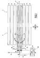
Figure 1 is a schematic top view of a linear Fresnel direct solar steam generator having a control system using a model predictive controller; -
Figure 2 is a block diagram illustrating an inlet controller of the control system of the solar steam generator offigure 1 ; -
Figure 3 is a block diagram illustrating an exit controller of the control system of the solar steam generator offigure 1 using the model prediction controller; -
Figure 4 is a block diagram illustrating an inlet controller according to another embodiment; and -
Figure 5 is a block diagram illustrating an exit controller according to another embodiment. - The direct
solar steam generator 2 illustrated onFigure 1 comprises a solar concentrator 4 and a receiver 6. The concentrator 4 is configured for reflecting and concentrating solar radiations towards the receiver 6. The receiver 6 is configured for circulation of a working fluid, e.g. water, and evaporation of the working fluid into steam using heat of the concentrated solar radiations. - The
solar steam generator 2 is of the linear type. The concentrator 4 and the receiver 6 are elongated in a longitudinal direction L. - Preferably, the concentrator 4 is of the Fresnel type. The concentrator 4 comprises a plurality of
separate reflectors 8 elongated in the longitudinal direction L and distributed in a transverse direction. Eachreflector 8 is pivotable about a longitudinal horizontal axis for reflecting solar radiations towards the receiver 6 depending on the position of the sun. - Preferably, the receiver 6 is placed at a height above the ground and the
reflectors 8 are placed at ground level and arranged for reflecting solar radiations upwards toward the receiver 6. - The
solar steam generator 2 comprises afeed line 10 for feeding working fluid in an essentially liquid state to the receiver 6 and asteam line 12 for collecting steam from the receiver 6. - The
solar steam generator 2 is of the direct type. The receiver 6 comprises a plurality of parallel tubes for circulation of the working fluid and evaporation of the working fluid into steam due to solar radiations concentrated onto the tubes. Each tube extends in the longitudinal direction between the two opposite longitudinal ends of the receiver 6. - The receiver 6 comprises
steam tubes 14 fed in parallel with working fluid from thefeed line 10 andsuperheat tubes 16 fed with steam from thesteam tubes 14 and feeding thesteam line 12 with superheated steam. - The
solar steam generator 2 comprises flow actuators for controlling flow parameter of working fluid through the receiver 6. - The flow actuators comprise inlet flow actuators for controlling parameters of the inlet flow entering the receiver 6. Preferably, inlet flow actuators comprise one
respective inlet valve 18 provided at the inlet end of eachsteam tube 14 for controlling parameters of inlet flow entering eachsteam tube 14 individually. - The flow actuators comprise outlet flow actuators for controlling parameters of the steam outlet flow exiting the receiver 6. Preferably, outlet flow actuators comprise one
single outlet valve 20 for controlling parameters of the outlet flow exiting thesuperheat tubes 16. - The
solar steam generator 2 comprises acontrol system 22 for controlling the flow actuators. Thecontrol system 22 comprises aninlet controller 24 for controllinginlet valves 18 and anoutlet controller 26 for controlling theoutlet valve 20. - According to one aspect of the invention, the
control system 22 comprises a modelpredictive controller 28 for determining control outputs for theinlet controller 24 and theoutlet controller 26. The modelpredictive controller 28 runs a computer model of the solar steam generator or a lookup tables-based model allowing it to predict behavior of the solar steam generator and a future state based on inputs representing the state of the solar steam generator at a current time. - The
inlet controller 24 and theoutlet controller 26 each control respectively theinlet valves 18 and theoutlet valve 20 depending on the control outputs determined by the modelpredictive controller 28. - The inputs of the model
predictive controller 28 are dependant parameters and/or independent parameters of thesolar steam generator 2. - An independent parameter is a parameter independent of the operation of the
solar steam generator 2. Insolation and position of the sun are examples of independent parameters. - A dependant parameter is a parameter varying depending on the operation of the
solar steam generator 2. Inlet flow, outlet flow, steam temperature, superheated steam temperature and steam pressure are examples of dependent parameters. - The
solar steam generator 2 comprisessensors 32 for sensing dependant parameters and/or independent parameters of thesolar steam generator 2. Thecontrol system 22 receives the signals of the sensors. Thecontrol system 22 uses these signals for controlling thesolar steam generator 2. Theinlet controller 24, theoutlet controller 26 and the modelpredictive controller 28 each use the signal(s) of one or several of thesensors 32. -
Sensors 32 may be of different types.Sensors 32 provided ontubes Figure 1 for sensing e.g. temperature or pressure. Additional sensors may be provided, namely for sensing insolation. - The
tubes bank 34 of tubes. Thecontrol system 22 is configured to control the operation of eachbank 34 of tubes individually. In a preferred embodiment, thetubes banks 34 of tubes. As illustrated onFigure 1 , eachbank 34 of tubes comprises a plurality ofsteam tubes 14, here threesteam tubes 14 and onesingle superheat tube 16 fed by thesteam tubes 14 of thebank 34. - The longitudinal direction L is oriented North-South as illustrated by the compass on
Figure 1 and thetubes east bank 34 of tubes comprising thetubes west bank 34 of tubes and awest bank 34 of tubes comprising thetubes bank 34 comprises a respective part of the plurality oftubes - In operation, working fluid in essentially liquid state circulates in the
feed line 10. The working fluid is fed to thesteam tubes 14 in parallel. The working fluid is evaporated in thesteam tubes 14 heated by the solar radiations concentrated onto thesteam tubes 14. The steam is feed to thesuperheat tubes 16. The steam is superheated in thesuperheat tubes 16 heated by the solar radiations concentrated onto thesuperheat tubes 16. Thecontrol system 22 controls theinlet valves 18 and theoutlet valve 20. - As illustrated in
Figure 2 , theinlet controller 24 is configured for controlling inlet mass flow rate in eachsteam tube 14 individually. In the following, unless specified otherwise, "flow" refers to mass flow rate - The
inlet controller 24 determines a tube inlet flow setpoint Wtube representative of a desired value for the inlet mass flow rate in eachsteam tube 14 individually and controls the position of theinlet valve 18 for equalizing a tube inlet flow estimate Wmes representative of the actual inlet mass flow rate in thesteam tube 14 with the tube inlet flow setpoint. - The
inlet controller 24 comprises an inlet maincontrol feedback loop 36 controlling the position of theinlet valve 18 for equalizing the tube inlet flow estimate Wmes with the tube inlet flow setpoint Wtube. - The inlet main
control feedback loop 36 comprises a tubeflow estimate controller 38 determining the tube inlet flow estimate Wmeas, a comparator determining the error, that is the difference between the tube inlet flow setpoint Wtube and the tube inlet flow estimate Wmeas and aninlet valve regulator 40 receiving the error and outputting an inlet valve control instruction Vin. In a preferred embodiment, eachinlet valve regulator 40 is a PID controller. - Only one inlet main
control feedback loop 36 is illustrated onFigure 2 for the sake of clarity. Theinlet controller 24 comprises an inlet maincontrol feedback loop 36 for eachsteam tube 14. - The
inlet controller 24 determines a total flow target representative Wssg of a desired value for the total flow in thesolar steam generator 2. The total flow target Wssg is used as a feedforward signal for determining the tube flow setpoints Wtube. Theinlet controller 24 comprises atotal flow controller 42 determining the total flow target Wssg as a function of independent parameters. - In a preferred embodiment, the total flow target Wssg is determined as a ratio of the thermal input Qin to an expected enthalpy rise ΔH of the working fluid in the receiver 6.
- The thermal input Qin is determined as a difference between a solar power input and a thermal loss. The solar power input is determined as a product of a measured direct normal insolation DNI and an optical efficiency η(az, el) of the concentrator 4 evaluated instantaneously at the solar position namely the azimuth az and elevation el of the sun.
- The thermal loss Qloss is predicted based on a model of the
solar steam generator 2 and depends on different independent parameters such as ambient temperature, wind spind and geometry of the receiver cavity. - The enthalpy of the working fluid is a function of the working fluid pressure and temperature. The enthalpy is implemented with industry standard steam tables (see IAPWS-IF97). The expected enthalpy rise ΔH is the difference between inlet enthalpy and outlet enthalpy. In a preferred embodiment, this value is set as a fixed constant value depending on nominal preset values of exit pressure Pout, exit temperature Tout, inlet pressure Pin and inlet temperature Tin.
- The total mass flow target is determined as a function of the following equations:


- The
inlet controller 24 determines for each bank of tubes a bank flow target Wbank as a function of the total flow target Wssg. The bank flow target Wbank is determined as a fraction of the total flow target Wssg corrected by a bank correction coefficient Rbank determined by the modelpredictive controller 28 for eachbank 34. Theinlet controller 24 determines each bank flow target Wbank by multiplying the total flow target by a bank fraction Fbank and by the bank correction coefficient Rbank of thebank 34. - In a preferred embodiment, the bank fraction Fbank is identical for the banks. In the example, the
solar steam generator 2 comprises two banks and the bank fraction Fbank equals 0.5. - Inputs of the model
predictive controller 28 comprise a feed temperature estimate Tin representative of the temperature of the working fluid in thefeed line 10. Sensors comprise at least one temperature sensor for measuring working fluid temperature in thefeed line 10. - Inputs of the model
predictive controller 28 comprise an exit temperature estimate Tout representative of the temperature of the steam in thesteam line 12. First sensors 30 comprise a temperature sensor for measuring temperature of the steam in thesteam line 12. - Inputs of the model
predictive controller 28 comprise the total flow target Wssg. - The
inlet controller 24 allocates a fraction of the bank flow target Wbank of eachbank 34 to thesteam tubes 14 of saidbank 34 fed in parallel with working fluid. Theinlet controller 24 comprises asplit controller 44 outputting a tube fraction Ftube for eachsteam tube 14. In a preferred embodiment, the tube fractions are fixed. The tube fractions Ftube are equal or different. In any case, the tube fractions Ftube are such that the sum of the tube fractions Ftube of the steam tubes of a bank equals 1. - The tube
flow estimate controller 38 determines the tube flow estimate Wmeas for eachsteam tube 14 as a function of the signal delivered by at least one sensor sensing a parameter related to flow in thesteam tubes 14. - In one embodiment, the
inlet controller 24 determines the tube flow estimate Wmeas as a function of signals delivered by mass flow meters located along thesteam tubes 14. - In an alternative embodiment, the tube flow estimates Wmes are determined as a function of a total bulk flow estimate Wbulk representative of bulk flow at receiver 6 inlet and determined based on the signal of a bulk flow meter provided on the
feed line 10. The inletflow estimate controller 38 determines the tube flow estimate in eachsteam tube 14 as the product of the total bulk flow estimate Wbulk with the ratio of the flow coefficient Cv of theinlet valve 18 of saidsteam tube 14 at the current valve position z with the sum of the flow coefficients Cv of theinlet valves 18 at the current valve positions z of the inlet valves. The flow coefficient Cv of a valve is a coefficient that relates the flow rate through a valve to the pressure drop taken across the valve. The flow coefficient Cv of a valve is related to its position z. This embodiment necessitates determining the flow coefficient curves defining the flow coefficient Cv of eachinlet valve 18 as a function of the position z of theinlet valve 18. Mass flow in each steam tube is determined by the following equation:
- As illustrated on
figure 3 , theexit controller 26 controls the position of theexit valve 20. Theexit controller 26 comprises an exitcontrol feedback loop 48 controlling theexit valve 20. The exitcontrol feedback loop 48 comprises exitpressure estimate controller 50 determining an exit pressure estimate Pout representative of superheat steam pressure at receiver outlet, a comparator determining an error as a difference between an exit pressure setpoint Pset and the exit pressure estimate Pout and anexit valve regulator 52 receiving the error and outputting an exit valve control instruction Vout. In a preferred embodiment, theexit valve regulator 52 is a PID controller. - The model
predictive controller 28 determines the exit pressure setpoint. Theexit controller 26 comprises an determining the exit pressure estimate. - In operation, the
inlet controller 24 determines the tube flow setpoints Wtube and controls theinlet valves 18 to minimize the difference between the tube flow setpoints Wtube and the tube flow estimates Wmeas. Theinlet controller 24 adjusts the position of theinlet valves 18 depending on the errors detected. - The model
predictive controller 28 is used to control the tube flow setpoints Wtube. The modelpredictive controller 28 receives dependant parameters as inputs. The modelpredictive controller 24 is arranged in a control feedback loop controlling the tube flow setpoints Wtube and acting as an outer control loop controlling setpoints for the inletcontrol feedback loops 36 acting as inner control loop. - Besides, the model
predictive controller 28 is used to directly set an exit pressure setpoint Pset. Eachexit valve 20 is controlled to minimize the difference between the exit pressure setpoint Pset and the exit pressure estimate Pmeas. - The model
predictive controller 28 predicts the state of thesolar steam generator 2 depending on inputs corresponding to current parameters. Prediction of the state in a future time allows controlling thesolar steam generator 2 with taking into account the reaction of thesolar steam generator 2 to the modification of the position of theinlet valves 18 and theoutlet valve 20. This allows enhancing control of thesolar steam generator 2. - Preferably, the model
predictive controller 28 solves the model in a flow normalized time. To this end, in an embodiment, the modelpredictive controller 28 scans the total flow target Wssg at a fast rate, e.g. every two seconds, and determines the next controller execution time based on the current flow target. If elapsed time since the last controller execution exceeds the desired next execution time, it samples variables required and calculates the next control outputs (Rbank, Pout). - In the embodiment of
Figures 2 and 3 , the total flow target Wssg is a feedforward signal calculated as a function of independent parameters. - In an alternative embodiment, the total flow target Wssg is determined with estimating the thermal input Qin as a function of dependent parameters. In a preferred embodiment, the thermal input Qin is calculated as the sum of the product of an exit steam flow Wsteam with the expected enthalpy rise ΔH and the product of the rate of change of exit pressure dPexit/dt and a factor Γ that relates thermal input power absorbed by the working fluid to the rate of change in exit pressure. The thermal input is calculated as per the following equation:

- In the
inlet controller 24 ofFigure 2 , thesplit controller 46 divides the bank flow target Wbank across thesteam tubes 14 by multiplying the bank flow target Wbank by a fixed tube fraction Ftube. - In the alternative embodiment of
Figure 4 , thesplit controller 46 varies the values of the tube fractions Ftube to equalize temperatures in an economizer section ofsteam tubes 14 of the receiver 6. The economizer section of thesteam tubes 14 is a section where steam is expected to be sub cooled. - The
split controller 46 controls the inlet tube flow setpoint Wtube for eachindividual steam tube 14 of eachbank 34 with a splitcontrol feedback loop 60 to equalize a temperature Tk estimate representative of the temperature in eachsteam tube 14 with the average temperature Tavg in all thesteam tubes 14 of the receiver 6, or alternatively in thesteam tubes 14 of thebank 34 comprising the consideredsteam tube 14. - The split
control feedback loop 60 comprises for each steam tube 14 afraction regulator 62 receiving in input the difference between the average temperature Tavg and the temperature estimate Tk of the steam tube 14 Tk and outputting a tube fraction. Thefraction regulator 62 is e.g. a PID controller. - The
fraction regulator 62 might lead to a bank flow target Wbank different from the sum of the tube flow targets Wtube of thesteam tubes 14 of thebank 34. - To account for this, the split
control feedback loop 60 further comprises an adjustingcontroller 64 for adjusting the bank flow target Wbank. The adjustingcontroller 64 receives the difference between the bank flow target Wbank and the sum of the tube flow targets ΣWtube of the tubes of the banks and outputs an adjustment value which is added to the bank flow Wbank target for determining an adjusted bank flow target Wadjusted. The adjustingcontroller 64 is e.g. a PID controller. Each tube flow target Wtube is determined as the product of the adjusted bank flow target Wadjusted with the tube fraction Ftube. - The
exit controller 26 ofFigure 3 is an exit pressure controller. Alternatively, theexit controller 26 is a flow controller. - In a preferred embodiment of an exit flow controller illustrated on
Figure 5 , the modelpredictive controller 28 is configured to output a superheat temperature target Tsuperheat representative of a desired value for the temperature of the superheated steam at the outlet of the receiver 6. - The
exit controller 26 comprises asuperheat temperature module 66 for determining a superheat temperature estimate. The superheat temperature estimate Tout is determined as a function of a temperature sensor located on thesteam line 12. - The
exit controller 26 comprises asuperheat controller 68 receiving as input the difference between the superheat temperature target Tsuperheat and the superheat temperature estimate Tout and output an exit control coefficient Rout. - The
exit controller 26 determines an exit flow setpoint Wset as the product of the total flow target with the exit control coefficient. Theexit valve regulator 52 receives the difference between the exit flow setpoint Wset and the exit steam flow estimate West and outputs an exit valve position instruction Vout. - According to the invention, it is possible to control a solar steam generator efficiently despite the numerous parameters, the varying external independent parameters such as insolation, to existence of long time delays and to inverse response to disturbance inputs.
Claims (16)
- Method for controlling a direct solar steam generator comprising a solar receiver having tubes (14, 16) fed with working fluid and subjected to concentrated solar energy for evaporating the working fluid into steam and flow actuators (18, 20), the flow actuators comprising outlet flow actuators (20) for controlling outlet flow exiting the receiver (6), the position of each flow actuator (18, 20) affecting flow parameters in the tubes (14, 16), the method comprising controlling the positions of the flow actuators (18, 20) as a function of at least one control output (Rbank, Pset, Rout) of a model predictive controller (28) configured to predict the behaviour of the direct solar steam generator (2) as a function of inputs comprising independent and/or dependant parameters of the direct solar steam generation system (2), wherein the method comprises controlling the outlet flow actuators (20) to equalize an exit pressure estimate (Pout) representative of a current value of the steam pressure at the outlet of the receiver with an exit pressure setpoint (Pset) representative of a desired value for the steam pressure at the outlet of the receiver (6), the exit pressure setpoint (Pset) being set by the model predictive controller (28).
- Method according to claim 1, comprising determining a flow parameter setpoint (Wtube, Wset) representative of a desired value for the flow parameter as a function of at least one output (Rbank, Rout) of the model predictive controller (28) and controlling the position of at least one flow actuator (18, 20) with a control feedback loop (36, 48) to equalize a flow parameter estimate (Wmeas, Wout) representative of the current flow parameter in the solar steam generator (2) with the flow parameter setpoint.
- Method according to claim 2, comprising determining a flow parameter target (Wbank) as a product of a flow parameter target (WssgxFbank) with the control coefficient (Rbank) and determining the main flow parameter setpoint (Wtube) as a function of the flow parameter target (Wbank).
- Method according to claims 2 or 3, comprising determining a bank flow target (Wbank, Wadjusted) representative of a target flow through a bank of tubes comprising a plurality of tubes (14) fed in parallel and allocating a fraction of the bank flow target (Wbank, Wadjusted) to each tube (14).
- Method according to claim 4, comprising allocating a fixed fraction (Ftube) to each tube (14).
- Method according to claim 4, comprising determining a varying tube fraction (Ftube) for each tube as a function a difference of a tube temperature estimate representative of working fluid temperature in the tube and an average temperature determined as the average of tube temperature estimates in a plurality of tubes.
- Method according to claim 6, wherein average temperature is determined as the average of tube temperature estimates in tubes ot the bank or in tubes of several banks of the solar receiver (6).
- Method according to claim 6 or 7, comprising adjusting the bank flow target as a function of the difference between the bank flow target and the sum of the tube flow targets of the tubes of the banks.
- Method according to any one of claims 2 - 8, comprising controlling a flow actuator as a function of an exit coefficient (Rout) output by a regulator as a function of a difference between a target steam temperature (Tsuperheat) representative of a temperature desired at the outlet of the receiver (6) determined by the model predictive controller (28) and a steam temperature estimate (Tout) representative of the current steam temperature at the outlet of the receiver (6).
- Method according to any one of claims 2-9, comprising determining an exit flow target (Wout) as the function of the product of a nominal flow target (Wssg) with an output of the regulator.
- Method according to any one of claims 2 - 10, comprising determining a total flow target representative of a desired value of the flow of working fluid through the receiver (6) as a function of a total inlet flow target determined as a ratio of a thermal input representative of a thermal input to the working fluid in the solar steam generator to an expected enthalpy rise representative of an enthalpy rise of the working fluid in the solar steam generator.
- Method according to claim 11, comprising determining the thermal input as the difference between a solar energy input representative if the solar energy received by the working fluid in the solar steam generator and a thermal loss representative of thermal loss of the working fluid in the solar steam generator.
- Method according to claim 11, comprising determining the thermal input as the addition of an exit steam flow measure and the product of an exit steam pressure change rate with a coefficient relating exit steam pressure change rate to flow.
- Method according to any one of claims 2 - 13, wherein the model predictive controller refreshes outputs in a flow normalized time.
- Method according to any one of the preceding claims, wherein the outlet flow actuators comprises exit valves (20), each exit valve (20) being controlled to equalize the exit pressure estimate (Pout) with the exit pressure setpoint (Pset) set by the model predictive controller (28).
- Control system for controlling a direct solar steam generator according to a method according to anyone of the preceding claims, the control system comprising a model predictive controller (28) configured to predict the behaviour of the direct solar steam generator (2) as a function of inputs comprising independent and/or dependant parameters of the direct solar steam generation system (2), the control system comprising at least one controller for controlling the positions of the flow actuators (18, 20) as a function of at least one control output (Rbank, Pset, Rout) of said model predictive controller (28), and for controlling the outlet flow actuators (20) to equalize an exit pressure estimate (Pout) representative of a current value of the steam pressure at the outlet of the receiver with an exit pressure setpoint (Pset) representative of a desired value for the steam pressure at the outlet of the receiver (6), the exit pressure setpoint (Pset) being set by the model predictive controller (28).
Priority Applications (2)
| Application Number | Priority Date | Filing Date | Title |
|---|---|---|---|
| ES11306526.2T ES2526591T3 (en) | 2011-11-21 | 2011-11-21 | Procedure to control a solar steam generator and corresponding control system |
| EP11306526.2A EP2594862B1 (en) | 2011-11-21 | 2011-11-21 | Method of controlling a direct solar steam generator and corresponding control system |
Applications Claiming Priority (1)
| Application Number | Priority Date | Filing Date | Title |
|---|---|---|---|
| EP11306526.2A EP2594862B1 (en) | 2011-11-21 | 2011-11-21 | Method of controlling a direct solar steam generator and corresponding control system |
Publications (2)
| Publication Number | Publication Date |
|---|---|
| EP2594862A1 EP2594862A1 (en) | 2013-05-22 |
| EP2594862B1 true EP2594862B1 (en) | 2014-10-08 |
Family
ID=45218595
Family Applications (1)
| Application Number | Title | Priority Date | Filing Date |
|---|---|---|---|
| EP11306526.2A Not-in-force EP2594862B1 (en) | 2011-11-21 | 2011-11-21 | Method of controlling a direct solar steam generator and corresponding control system |
Country Status (2)
| Country | Link |
|---|---|
| EP (1) | EP2594862B1 (en) |
| ES (1) | ES2526591T3 (en) |
Families Citing this family (3)
| Publication number | Priority date | Publication date | Assignee | Title |
|---|---|---|---|---|
| CN108561866A (en) * | 2018-04-20 | 2018-09-21 | 青岛中正周和科技发展有限公司 | A kind of solar steam generator of Diameter of connecting pipe variation |
| CN110397898B (en) * | 2018-04-24 | 2022-08-23 | 山东力诺瑞特节能环保科技有限公司 | Cloud processing solar steam generator with intelligent water level control function |
| CN110286591A (en) * | 2019-06-21 | 2019-09-27 | 西安交通大学 | A Feedforward-Feedback Composite Control Method and Measurement and Control Method Based on the Method |
Family Cites Families (4)
| Publication number | Priority date | Publication date | Assignee | Title |
|---|---|---|---|---|
| US20080127647A1 (en) * | 2006-09-15 | 2008-06-05 | Skyfuel, Inc. | Solar-Generated Steam Retrofit for Supplementing Natural-Gas Combustion at Combined Cycle Power Plants |
| US8001960B2 (en) * | 2007-11-12 | 2011-08-23 | Brightsource Industries (Israel) Ltd. | Method and control system for operating a solar power tower system |
| EP2430370A2 (en) * | 2009-05-15 | 2012-03-21 | Areva Solar, Inc | Systems and methods for producing steam using solar radiation |
| US9003795B2 (en) * | 2009-11-24 | 2015-04-14 | Brightsource Industries (Israel) Ltd. | Method and apparatus for operating a solar steam system |
-
2011
- 2011-11-21 ES ES11306526.2T patent/ES2526591T3/en active Active
- 2011-11-21 EP EP11306526.2A patent/EP2594862B1/en not_active Not-in-force
Also Published As
| Publication number | Publication date |
|---|---|
| EP2594862A1 (en) | 2013-05-22 |
| ES2526591T3 (en) | 2015-01-13 |
Similar Documents
| Publication | Publication Date | Title |
|---|---|---|
| CN102741616B (en) | Systems and methods for producing steam using solar radiation | |
| US20080184789A1 (en) | Method of operating a solar thermal process heat plant and solar thermal process heat plant | |
| Bortolato et al. | Experimental study of a parabolic trough solar collector with flat bar-and-plate absorber during direct steam generation | |
| CA3219407C (en) | Multi-objective steam temperature control | |
| US20130048114A1 (en) | Controlled hydronic distribution system | |
| Abutayeh et al. | Balancing heat transfer fluid flow in solar fields | |
| WO2012027654A2 (en) | System and method for control and optimization of a pulverized coal boiler system | |
| US20120040298A1 (en) | Steam Temperature Control Using Dynamic Matrix Control | |
| Rodat et al. | Dynamic simulations of Fresnel solar power plants | |
| EP2594862A1 (en) | Method of controlling a direct solar steam generator and corresponding control system | |
| García et al. | Transient simulation of a control strategy for solar receivers based on mass flow valves adjustments and heliostats aiming | |
| US20140116422A1 (en) | Solar concentrating system | |
| Noureldin et al. | Modelling an automatic controller for parabolic trough solar fields under realistic weather conditions | |
| Oberkirsch et al. | Validation of a closed-loop aim point management system at the Jülich solar tower | |
| CN109059302B (en) | A kind of boiler group control adaptive temperature control method and system | |
| AU2005261689B2 (en) | Process for operating a continuous steam generator | |
| CN103080648A (en) | Method of operation of solar heated once-through steam generator and solar once-through steam generator | |
| US10101021B2 (en) | Control method for operating a heat recovery steam generator | |
| US20130319403A1 (en) | Method for operating a solar-thermal parabolic trough power plant | |
| JP5723220B2 (en) | Power plant | |
| EP2918961B1 (en) | Control of a flow of fluid through a heat exchanger | |
| US20220034240A1 (en) | Method and controller for preventing formation of droplets in a heat exchanger | |
| Machado et al. | Fresnel Solar Collector Control With Active Defocus | |
| AU2026201223A1 (en) | Method and system for controlling the operation of a CSP receiver | |
| JP5755098B2 (en) | Heat collection system |
Legal Events
| Date | Code | Title | Description |
|---|---|---|---|
| PUAI | Public reference made under article 153(3) epc to a published international application that has entered the european phase |
Free format text: ORIGINAL CODE: 0009012 |
|
| AK | Designated contracting states |
Kind code of ref document: A1 Designated state(s): AL AT BE BG CH CY CZ DE DK EE ES FI FR GB GR HR HU IE IS IT LI LT LU LV MC MK MT NL NO PL PT RO RS SE SI SK SM TR |
|
| AX | Request for extension of the european patent |
Extension state: BA ME |
|
| 17P | Request for examination filed |
Effective date: 20131022 |
|
| RBV | Designated contracting states (corrected) |
Designated state(s): AL AT BE BG CH CY CZ DE DK EE ES FI FR GB GR HR HU IE IS IT LI LT LU LV MC MK MT NL NO PL PT RO RS SE SI SK SM TR |
|
| RIC1 | Information provided on ipc code assigned before grant |
Ipc: F24J 2/07 20060101AFI20140131BHEP Ipc: F22B 35/02 20060101ALI20140131BHEP Ipc: F22B 1/00 20060101ALI20140131BHEP |
|
| GRAP | Despatch of communication of intention to grant a patent |
Free format text: ORIGINAL CODE: EPIDOSNIGR1 |
|
| INTG | Intention to grant announced |
Effective date: 20140430 |
|
| GRAS | Grant fee paid |
Free format text: ORIGINAL CODE: EPIDOSNIGR3 |
|
| GRAA | (expected) grant |
Free format text: ORIGINAL CODE: 0009210 |
|
| AK | Designated contracting states |
Kind code of ref document: B1 Designated state(s): AL AT BE BG CH CY CZ DE DK EE ES FI FR GB GR HR HU IE IS IT LI LT LU LV MC MK MT NL NO PL PT RO RS SE SI SK SM TR |
|
| REG | Reference to a national code |
Ref country code: GB Ref legal event code: FG4D |
|
| REG | Reference to a national code |
Ref country code: CH Ref legal event code: EP Ref country code: AT Ref legal event code: REF Ref document number: 690844 Country of ref document: AT Kind code of ref document: T Effective date: 20141015 |
|
| REG | Reference to a national code |
Ref country code: IE Ref legal event code: FG4D |
|
| REG | Reference to a national code |
Ref country code: DE Ref legal event code: R096 Ref document number: 602011010410 Country of ref document: DE Effective date: 20141120 |
|
| REG | Reference to a national code |
Ref country code: ES Ref legal event code: FG2A Ref document number: 2526591 Country of ref document: ES Kind code of ref document: T3 Effective date: 20150113 |
|
| REG | Reference to a national code |
Ref country code: NL Ref legal event code: VDEP Effective date: 20141008 |
|
| REG | Reference to a national code |
Ref country code: AT Ref legal event code: MK05 Ref document number: 690844 Country of ref document: AT Kind code of ref document: T Effective date: 20141008 |
|
| REG | Reference to a national code |
Ref country code: LT Ref legal event code: MG4D |
|
| PG25 | Lapsed in a contracting state [announced via postgrant information from national office to epo] |
Ref country code: NL Free format text: LAPSE BECAUSE OF FAILURE TO SUBMIT A TRANSLATION OF THE DESCRIPTION OR TO PAY THE FEE WITHIN THE PRESCRIBED TIME-LIMIT Effective date: 20141008 |
|
| PG25 | Lapsed in a contracting state [announced via postgrant information from national office to epo] |
Ref country code: NO Free format text: LAPSE BECAUSE OF FAILURE TO SUBMIT A TRANSLATION OF THE DESCRIPTION OR TO PAY THE FEE WITHIN THE PRESCRIBED TIME-LIMIT Effective date: 20150108 Ref country code: FI Free format text: LAPSE BECAUSE OF FAILURE TO SUBMIT A TRANSLATION OF THE DESCRIPTION OR TO PAY THE FEE WITHIN THE PRESCRIBED TIME-LIMIT Effective date: 20141008 Ref country code: PT Free format text: LAPSE BECAUSE OF FAILURE TO SUBMIT A TRANSLATION OF THE DESCRIPTION OR TO PAY THE FEE WITHIN THE PRESCRIBED TIME-LIMIT Effective date: 20150209 Ref country code: LT Free format text: LAPSE BECAUSE OF FAILURE TO SUBMIT A TRANSLATION OF THE DESCRIPTION OR TO PAY THE FEE WITHIN THE PRESCRIBED TIME-LIMIT Effective date: 20141008 Ref country code: IS Free format text: LAPSE BECAUSE OF FAILURE TO SUBMIT A TRANSLATION OF THE DESCRIPTION OR TO PAY THE FEE WITHIN THE PRESCRIBED TIME-LIMIT Effective date: 20150208 |
|
| PG25 | Lapsed in a contracting state [announced via postgrant information from national office to epo] |
Ref country code: GR Free format text: LAPSE BECAUSE OF FAILURE TO SUBMIT A TRANSLATION OF THE DESCRIPTION OR TO PAY THE FEE WITHIN THE PRESCRIBED TIME-LIMIT Effective date: 20150109 Ref country code: SE Free format text: LAPSE BECAUSE OF FAILURE TO SUBMIT A TRANSLATION OF THE DESCRIPTION OR TO PAY THE FEE WITHIN THE PRESCRIBED TIME-LIMIT Effective date: 20141008 Ref country code: HR Free format text: LAPSE BECAUSE OF FAILURE TO SUBMIT A TRANSLATION OF THE DESCRIPTION OR TO PAY THE FEE WITHIN THE PRESCRIBED TIME-LIMIT Effective date: 20141008 Ref country code: PL Free format text: LAPSE BECAUSE OF FAILURE TO SUBMIT A TRANSLATION OF THE DESCRIPTION OR TO PAY THE FEE WITHIN THE PRESCRIBED TIME-LIMIT Effective date: 20141008 Ref country code: AT Free format text: LAPSE BECAUSE OF FAILURE TO SUBMIT A TRANSLATION OF THE DESCRIPTION OR TO PAY THE FEE WITHIN THE PRESCRIBED TIME-LIMIT Effective date: 20141008 Ref country code: LV Free format text: LAPSE BECAUSE OF FAILURE TO SUBMIT A TRANSLATION OF THE DESCRIPTION OR TO PAY THE FEE WITHIN THE PRESCRIBED TIME-LIMIT Effective date: 20141008 Ref country code: RS Free format text: LAPSE BECAUSE OF FAILURE TO SUBMIT A TRANSLATION OF THE DESCRIPTION OR TO PAY THE FEE WITHIN THE PRESCRIBED TIME-LIMIT Effective date: 20141008 Ref country code: CY Free format text: LAPSE BECAUSE OF FAILURE TO SUBMIT A TRANSLATION OF THE DESCRIPTION OR TO PAY THE FEE WITHIN THE PRESCRIBED TIME-LIMIT Effective date: 20141008 |
|
| REG | Reference to a national code |
Ref country code: DE Ref legal event code: R119 Ref document number: 602011010410 Country of ref document: DE |
|
| PG25 | Lapsed in a contracting state [announced via postgrant information from national office to epo] |
Ref country code: BE Free format text: LAPSE BECAUSE OF NON-PAYMENT OF DUE FEES Effective date: 20141130 |
|
| REG | Reference to a national code |
Ref country code: CH Ref legal event code: PL |
|
| PG25 | Lapsed in a contracting state [announced via postgrant information from national office to epo] |
Ref country code: CZ Free format text: LAPSE BECAUSE OF FAILURE TO SUBMIT A TRANSLATION OF THE DESCRIPTION OR TO PAY THE FEE WITHIN THE PRESCRIBED TIME-LIMIT Effective date: 20141008 Ref country code: CH Free format text: LAPSE BECAUSE OF NON-PAYMENT OF DUE FEES Effective date: 20141130 Ref country code: RO Free format text: LAPSE BECAUSE OF FAILURE TO SUBMIT A TRANSLATION OF THE DESCRIPTION OR TO PAY THE FEE WITHIN THE PRESCRIBED TIME-LIMIT Effective date: 20141008 Ref country code: SK Free format text: LAPSE BECAUSE OF FAILURE TO SUBMIT A TRANSLATION OF THE DESCRIPTION OR TO PAY THE FEE WITHIN THE PRESCRIBED TIME-LIMIT Effective date: 20141008 Ref country code: DK Free format text: LAPSE BECAUSE OF FAILURE TO SUBMIT A TRANSLATION OF THE DESCRIPTION OR TO PAY THE FEE WITHIN THE PRESCRIBED TIME-LIMIT Effective date: 20141008 Ref country code: EE Free format text: LAPSE BECAUSE OF FAILURE TO SUBMIT A TRANSLATION OF THE DESCRIPTION OR TO PAY THE FEE WITHIN THE PRESCRIBED TIME-LIMIT Effective date: 20141008 Ref country code: MC Free format text: LAPSE BECAUSE OF FAILURE TO SUBMIT A TRANSLATION OF THE DESCRIPTION OR TO PAY THE FEE WITHIN THE PRESCRIBED TIME-LIMIT Effective date: 20141008 Ref country code: LI Free format text: LAPSE BECAUSE OF NON-PAYMENT OF DUE FEES Effective date: 20141130 |
|
| PLBE | No opposition filed within time limit |
Free format text: ORIGINAL CODE: 0009261 |
|
| STAA | Information on the status of an ep patent application or granted ep patent |
Free format text: STATUS: NO OPPOSITION FILED WITHIN TIME LIMIT |
|
| REG | Reference to a national code |
Ref country code: IE Ref legal event code: MM4A |
|
| 26N | No opposition filed |
Effective date: 20150709 |
|
| REG | Reference to a national code |
Ref country code: FR Ref legal event code: PLFP Year of fee payment: 5 |
|
| PG25 | Lapsed in a contracting state [announced via postgrant information from national office to epo] |
Ref country code: IE Free format text: LAPSE BECAUSE OF NON-PAYMENT OF DUE FEES Effective date: 20141121 Ref country code: DE Free format text: LAPSE BECAUSE OF NON-PAYMENT OF DUE FEES Effective date: 20150602 |
|
| PGFP | Annual fee paid to national office [announced via postgrant information from national office to epo] |
Ref country code: TR Payment date: 20151021 Year of fee payment: 5 Ref country code: IT Payment date: 20151124 Year of fee payment: 5 |
|
| PG25 | Lapsed in a contracting state [announced via postgrant information from national office to epo] |
Ref country code: SI Free format text: LAPSE BECAUSE OF FAILURE TO SUBMIT A TRANSLATION OF THE DESCRIPTION OR TO PAY THE FEE WITHIN THE PRESCRIBED TIME-LIMIT Effective date: 20141008 |
|
| PGFP | Annual fee paid to national office [announced via postgrant information from national office to epo] |
Ref country code: ES Payment date: 20151014 Year of fee payment: 5 Ref country code: FR Payment date: 20151008 Year of fee payment: 5 |
|
| PG25 | Lapsed in a contracting state [announced via postgrant information from national office to epo] |
Ref country code: SM Free format text: LAPSE BECAUSE OF FAILURE TO SUBMIT A TRANSLATION OF THE DESCRIPTION OR TO PAY THE FEE WITHIN THE PRESCRIBED TIME-LIMIT Effective date: 20141008 |
|
| PG25 | Lapsed in a contracting state [announced via postgrant information from national office to epo] |
Ref country code: BG Free format text: LAPSE BECAUSE OF FAILURE TO SUBMIT A TRANSLATION OF THE DESCRIPTION OR TO PAY THE FEE WITHIN THE PRESCRIBED TIME-LIMIT Effective date: 20141008 |
|
| GBPC | Gb: european patent ceased through non-payment of renewal fee |
Effective date: 20151121 |
|
| PG25 | Lapsed in a contracting state [announced via postgrant information from national office to epo] |
Ref country code: HU Free format text: LAPSE BECAUSE OF FAILURE TO SUBMIT A TRANSLATION OF THE DESCRIPTION OR TO PAY THE FEE WITHIN THE PRESCRIBED TIME-LIMIT; INVALID AB INITIO Effective date: 20111121 Ref country code: MT Free format text: LAPSE BECAUSE OF FAILURE TO SUBMIT A TRANSLATION OF THE DESCRIPTION OR TO PAY THE FEE WITHIN THE PRESCRIBED TIME-LIMIT Effective date: 20141008 Ref country code: LU Free format text: LAPSE BECAUSE OF NON-PAYMENT OF DUE FEES Effective date: 20141121 |
|
| PG25 | Lapsed in a contracting state [announced via postgrant information from national office to epo] |
Ref country code: GB Free format text: LAPSE BECAUSE OF NON-PAYMENT OF DUE FEES Effective date: 20151121 |
|
| REG | Reference to a national code |
Ref country code: FR Ref legal event code: ST Effective date: 20170731 |
|
| PG25 | Lapsed in a contracting state [announced via postgrant information from national office to epo] |
Ref country code: FR Free format text: LAPSE BECAUSE OF NON-PAYMENT OF DUE FEES Effective date: 20161130 Ref country code: IT Free format text: LAPSE BECAUSE OF NON-PAYMENT OF DUE FEES Effective date: 20161121 |
|
| PG25 | Lapsed in a contracting state [announced via postgrant information from national office to epo] |
Ref country code: ES Free format text: LAPSE BECAUSE OF NON-PAYMENT OF DUE FEES Effective date: 20161122 |
|
| REG | Reference to a national code |
Ref country code: ES Ref legal event code: FD2A Effective date: 20180627 |
|
| PG25 | Lapsed in a contracting state [announced via postgrant information from national office to epo] |
Ref country code: MK Free format text: LAPSE BECAUSE OF FAILURE TO SUBMIT A TRANSLATION OF THE DESCRIPTION OR TO PAY THE FEE WITHIN THE PRESCRIBED TIME-LIMIT Effective date: 20141008 |
|
| PG25 | Lapsed in a contracting state [announced via postgrant information from national office to epo] |
Ref country code: AL Free format text: LAPSE BECAUSE OF FAILURE TO SUBMIT A TRANSLATION OF THE DESCRIPTION OR TO PAY THE FEE WITHIN THE PRESCRIBED TIME-LIMIT Effective date: 20141008 |
|
| PG25 | Lapsed in a contracting state [announced via postgrant information from national office to epo] |
Ref country code: TR Free format text: LAPSE BECAUSE OF NON-PAYMENT OF DUE FEES Effective date: 20161121 |