EP2594774A2 - Reversible flow discharge orifice - Google Patents
Reversible flow discharge orifice Download PDFInfo
- Publication number
- EP2594774A2 EP2594774A2 EP12192435.1A EP12192435A EP2594774A2 EP 2594774 A2 EP2594774 A2 EP 2594774A2 EP 12192435 A EP12192435 A EP 12192435A EP 2594774 A2 EP2594774 A2 EP 2594774A2
- Authority
- EP
- European Patent Office
- Prior art keywords
- throat
- exit ramp
- orifice
- radius
- exit
- Prior art date
- Legal status (The legal status is an assumption and is not a legal conclusion. Google has not performed a legal analysis and makes no representation as to the accuracy of the status listed.)
- Granted
Links
Images

Classifications
-
- F—MECHANICAL ENGINEERING; LIGHTING; HEATING; WEAPONS; BLASTING
- F02—COMBUSTION ENGINES; HOT-GAS OR COMBUSTION-PRODUCT ENGINE PLANTS
- F02K—JET-PROPULSION PLANTS
- F02K9/00—Rocket-engine plants, i.e. plants carrying both fuel and oxidant therefor; Control thereof
- F02K9/42—Rocket-engine plants, i.e. plants carrying both fuel and oxidant therefor; Control thereof using liquid or gaseous propellants
- F02K9/44—Feeding propellants
- F02K9/56—Control
- F02K9/566—Control elements and safety devices, e.g. pressure relief valves
-
- F—MECHANICAL ENGINEERING; LIGHTING; HEATING; WEAPONS; BLASTING
- F02—COMBUSTION ENGINES; HOT-GAS OR COMBUSTION-PRODUCT ENGINE PLANTS
- F02K—JET-PROPULSION PLANTS
- F02K9/00—Rocket-engine plants, i.e. plants carrying both fuel and oxidant therefor; Control thereof
- F02K9/42—Rocket-engine plants, i.e. plants carrying both fuel and oxidant therefor; Control thereof using liquid or gaseous propellants
- F02K9/60—Constructional parts; Details not otherwise provided for
- F02K9/62—Combustion or thrust chambers
- F02K9/64—Combustion or thrust chambers having cooling arrangements
-
- F—MECHANICAL ENGINEERING; LIGHTING; HEATING; WEAPONS; BLASTING
- F02—COMBUSTION ENGINES; HOT-GAS OR COMBUSTION-PRODUCT ENGINE PLANTS
- F02K—JET-PROPULSION PLANTS
- F02K9/00—Rocket-engine plants, i.e. plants carrying both fuel and oxidant therefor; Control thereof
- F02K9/97—Rocket nozzles
- F02K9/972—Fluid cooling arrangements for nozzles
-
- F—MECHANICAL ENGINEERING; LIGHTING; HEATING; WEAPONS; BLASTING
- F15—FLUID-PRESSURE ACTUATORS; HYDRAULICS OR PNEUMATICS IN GENERAL
- F15D—FLUID DYNAMICS, i.e. METHODS OR MEANS FOR INFLUENCING THE FLOW OF GASES OR LIQUIDS
- F15D1/00—Influencing flow of fluids
- F15D1/02—Influencing flow of fluids in pipes or conduits
- F15D1/025—Influencing flow of fluids in pipes or conduits by means of orifice or throttle elements
-
- F—MECHANICAL ENGINEERING; LIGHTING; HEATING; WEAPONS; BLASTING
- F16—ENGINEERING ELEMENTS AND UNITS; GENERAL MEASURES FOR PRODUCING AND MAINTAINING EFFECTIVE FUNCTIONING OF MACHINES OR INSTALLATIONS; THERMAL INSULATION IN GENERAL
- F16L—PIPES; JOINTS OR FITTINGS FOR PIPES; SUPPORTS FOR PIPES, CABLES OR PROTECTIVE TUBING; MEANS FOR THERMAL INSULATION IN GENERAL
- F16L55/00—Devices or appurtenances for use in, or in connection with, pipes or pipe systems
- F16L55/02—Energy absorbers; Noise absorbers
- F16L55/027—Throttle passages
-
- G—PHYSICS
- G05—CONTROLLING; REGULATING
- G05D—SYSTEMS FOR CONTROLLING OR REGULATING NON-ELECTRIC VARIABLES
- G05D7/00—Control of flow
- G05D7/01—Control of flow without auxiliary power
- G05D7/0186—Control of flow without auxiliary power without moving parts
Definitions
- This disclosure relates to a reversible-flow discharge orifice, for example, for use in a rocket engine fluid-flow system, such as a fuel system.
- One type of rocket fuel system includes a pump that provides fuel, such as liquid hydrogen, to a combustion chamber.
- the pumped fuel passes through a discharge orifice before being provided to coolant tubes surrounding a nozzle that is downstream from the combustion chamber.
- One typical discharge orifice provides a flow resistance that allows the fuel pump to meet the engine's design parameters for combustion chamber pressure and propellant mixture-ratio range during steady-state operation.
- Typical discharge orifices used in such applications have a well-rounded entrance, a constant-diameter throat and a squared-off trailing edge having a ninety-degree, sharp corner, which provide a repeatable, non-recoverable pressure drop for the flow of liquid hydrogen from the pump to the coolant tubes.
- shutoff valve which is arranged downstream from the coolant tubes and before the combustion chamber, is closed and the hydrogen flow is reversed to evacuate the hydrogen from the system, including the coolant tubes.
- a fluid flow system includes an orifice having a throat.
- the orifice includes entrance and exit ramps adjoining either side of the throat.
- the entrance ramp provides a smooth approach to the orifice throat.
- the exit ramp includes an exit ramp surface having a divergent angle of 20-60°.
- An exit ramp radius adjoins the exit ramp surface at a location near the throat. The exit ramp radius is less than twice the throat radius.
- a rocket engine fluid flow system includes a pump fluidly interconnecting a fluid source to a combustion chamber.
- a nozzle is in fluid communication with the combustion chamber and includes coolant tubes fluidly arranged between the pump and the combustion chamber.
- An orifice has a throat and is fluidly arranged between the pump and the coolant tubes.
- the orifice has entrance and exit ramps arranged on either side of the throat.
- the exit ramp has an exit ramp surface with a divergent angle that is less than a right angle.
- a method of managing fluid flow within a fuel system includes the steps of flowing fluid through an orifice in a first direction to a combustion chamber.
- a shutdown sequence is initiated.
- the flow through the orifice is reversed to a second direction that is opposite the first direction.
- the flow through the orifice in the second direction provides a desired low pressured drop across the orifice during the shutdown sequence.
- a rocket engine fuel flow system 10 is schematically illustrated in Figure 1 .
- the system 10 includes a fuel supply 12, such as liquid hydrogen, that is provided to an engine 14.
- a fuel pump 16 includes first and second stages 18, 20. Fuel flows from the pump discharge through an orifice 24 to coolant tubes 26.
- the orifice 24 creates a significant pressure loss, unlike a venturi, and it produces flow separation that provides stable flow.
- the discharge valve 22 also includes a vent 38 which is normally blocked during steady-state operation.
- the engine 14 includes a nozzle 15 attached to a combustion chamber 36.
- a fuel and an oxidant, such as hydrogen and oxygen are combusted in the combustion chamber 36 and expelled through the nozzle 15.
- the walls of the combustion chamber and nozzle are comprised of coolant tubes.
- the hydrogen vaporizes in the coolant tubes 26.
- the fuel is pumped through the orifice 24 then through the coolant tubes 26 then through the turbine then through the shutoff valve 32, which is open, to an injector 34.
- the injector 34 provides the gaseous hydrogen to the combustion chamber 36 where it is mixed with oxygen and combusted.
- the main shutoff valve 32 is closed and the hydrogen fuel flow direction between the pump and the shutoff valve is reversed.
- the discharge valve 22 is actuated to a vented position to fluidly connect the coolant tubes 26 with the vent 38, which is open to atmosphere.
- the fuel flow is reversed through the system 10, including through the orifice 24. It is desirable to minimize the pressure drop across the orifice during reverse flow
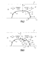
- the orifice 24 is illustrated in more detail in Figures 2 and 3 .
- steady-state flow is indicated by the large arrow, and reverse flow is indicated by the clusters of small arrows.
- the orifice 24 is arranged within an inner diameter 44 of a tube 40 through which the fluid flows.
- An outer diameter 42 of the orifice 24 engages the tube inner diameter 44.
- the orifice 24 includes a throat 50 having a throat radius R relative to a flow axis A.
- Entrance and exit ramps 52, 54 are provided on either side of the throat 50.
- the entrance ramp 52 includes a convergent radius 53 and provides a smooth entrance 46 to the orifice throat during steady-state operation.
- the exit ramp 54 includes a divergent angle 48 that is arranged on a downstream side 47 during steady-state operation.
- the prior art square-cornered exit resulted in a high pressure differential between the interior of the combustion chamber 36 and the coolant tubes 26 during shutdown.
- the exit ramp end 48 is less than a right angle, for example, rounded slightly, to reduce resistance during reverse flow without compromising desired flow separation during steady-state forward flow.
- the exit ramp 54 includes an exit ramp surface 58 arranged at a divergent angle 56, for example, 20-60°, relative to the orifice centerline.
- An exit ramp radius 60 adjoins and is tangent to the exit ramp surface 58 and is tangent to the throat 50.
- the exit ramp radius 60 is less than twice the dimension of the throat radius R, in one example, to avoid flow-increasing diffusion in the steady-state flow direction and is also less than the entrance-ramp radius 53.
- the orifice 124 includes an annular step 62, which is ninety degrees in one example, provided by first and second surfaces 64, 66 that adjoin one another.
- the first and second surfaces 64, 66 respectively provide a depth 68 from the throat 50 and a length 70 from the first surface 64 to the exit ramp radius 160.
- the step 62 is large enough to enable consistent flow separation during steady-state (forward) flow, yet small enough to enable low pressure drop when the flow through the orifice is reversed.
- the annular-step depth 68 is 25 mils (0.64 mm), and the length 70 is at least twice the depth 68.
- An exit ramp surface 158 adjoins and is tangent to the exit ramp radius 160, which is tangent to the second surface 66.
- the fuel flow within a fuel system is managed by flowing fluid through the orifice 24 in a first direction (indicated by the arrows in Figure 1 ) to the combustion chamber 36. Desired flow resistance is maintained through the orifice 24.
- a shut-down sequence is initiated, by a controller, for example, when fuel is no longer desired at the combustion chamber 36.
- the fuel flow is reversed through the orifice 24. The flow though the orifice 24 in the reverse direction provides a desired low pressure drop across the orifice 24 during the shut-down sequence.
Landscapes
- Engineering & Computer Science (AREA)
- General Engineering & Computer Science (AREA)
- Mechanical Engineering (AREA)
- Chemical & Material Sciences (AREA)
- Combustion & Propulsion (AREA)
- Physics & Mathematics (AREA)
- Fluid Mechanics (AREA)
- General Physics & Mathematics (AREA)
- Automation & Control Theory (AREA)
- Jet Pumps And Other Pumps (AREA)
Abstract

Description
- This disclosure relates to a reversible-flow discharge orifice, for example, for use in a rocket engine fluid-flow system, such as a fuel system.
- One type of rocket fuel system includes a pump that provides fuel, such as liquid hydrogen, to a combustion chamber. The pumped fuel passes through a discharge orifice before being provided to coolant tubes surrounding a nozzle that is downstream from the combustion chamber.
- One typical discharge orifice provides a flow resistance that allows the fuel pump to meet the engine's design parameters for combustion chamber pressure and propellant mixture-ratio range during steady-state operation. Typical discharge orifices used in such applications have a well-rounded entrance, a constant-diameter throat and a squared-off trailing edge having a ninety-degree, sharp corner, which provide a repeatable, non-recoverable pressure drop for the flow of liquid hydrogen from the pump to the coolant tubes.
- During an engine shutdown procedure, the flow rate of liquid hydrogen through the discharge orifice is reversed. Typically, a shutoff valve, which is arranged downstream from the coolant tubes and before the combustion chamber, is closed and the hydrogen flow is reversed to evacuate the hydrogen from the system, including the coolant tubes.
- A fluid flow system is provided that includes an orifice having a throat. The orifice includes entrance and exit ramps adjoining either side of the throat. The entrance ramp provides a smooth approach to the orifice throat. The exit ramp includes an exit ramp surface having a divergent angle of 20-60°. An exit ramp radius adjoins the exit ramp surface at a location near the throat. The exit ramp radius is less than twice the throat radius.
- A rocket engine fluid flow system includes a pump fluidly interconnecting a fluid source to a combustion chamber. A nozzle is in fluid communication with the combustion chamber and includes coolant tubes fluidly arranged between the pump and the combustion chamber. An orifice has a throat and is fluidly arranged between the pump and the coolant tubes. The orifice has entrance and exit ramps arranged on either side of the throat. The exit ramp has an exit ramp surface with a divergent angle that is less than a right angle.
- A method of managing fluid flow within a fuel system includes the steps of flowing fluid through an orifice in a first direction to a combustion chamber. A shutdown sequence is initiated. The flow through the orifice is reversed to a second direction that is opposite the first direction. The flow through the orifice in the second direction provides a desired low pressured drop across the orifice during the shutdown sequence.
- The disclosure can be further understood by reference to the following detailed description when considered in connection with the accompanying drawings wherein:
-
Figure 1 is a schematic view of a rocket engine fluid flow system. -
Figure 2 is a schematic view of a fluid flow system, including an example of the disclosed reversible-flow discharge orifice. -
Figure 3 is an enlarged view of the reversible-flow discharge orifice shown inFigure 2 . -
Figure 4 is another example of a reversible-flow discharge orifice. - A rocket engine
fuel flow system 10 is schematically illustrated inFigure 1 . Thesystem 10 includes afuel supply 12, such as liquid hydrogen, that is provided to anengine 14. In one example, afuel pump 16 includes first andsecond stages orifice 24 tocoolant tubes 26. Theorifice 24 creates a significant pressure loss, unlike a venturi, and it produces flow separation that provides stable flow. Thedischarge valve 22 also includes avent 38 which is normally blocked during steady-state operation. - The
engine 14 includes anozzle 15 attached to acombustion chamber 36. A fuel and an oxidant, such as hydrogen and oxygen are combusted in thecombustion chamber 36 and expelled through thenozzle 15. - The walls of the combustion chamber and nozzle are comprised of coolant tubes. The hydrogen vaporizes in the
coolant tubes 26. During steady-state operation of the engine, the fuel is pumped through theorifice 24 then through thecoolant tubes 26 then through the turbine then through theshutoff valve 32, which is open, to aninjector 34. Theinjector 34 provides the gaseous hydrogen to thecombustion chamber 36 where it is mixed with oxygen and combusted. - During steady-state operation fluid flows through the
system 10 in the direction indicated by the arrows inFigure 1 . Thedischarge valve 22 has an open position, which is described above with respect to the steady-state operation. During shut-down, it is desirable to evacuate the fuel from thesystem 10, including thecoolant tubes 26. - During the shut-down sequence, the
main shutoff valve 32 is closed and the hydrogen fuel flow direction between the pump and the shutoff valve is reversed. Thedischarge valve 22 is actuated to a vented position to fluidly connect thecoolant tubes 26 with thevent 38, which is open to atmosphere. The fuel flow is reversed through thesystem 10, including through theorifice 24. It is desirable to minimize the pressure drop across the orifice during reverse flow - The
orifice 24 is illustrated in more detail inFigures 2 and3 . InFigure 2 , steady-state flow is indicated by the large arrow, and reverse flow is indicated by the clusters of small arrows. Theorifice 24 is arranged within aninner diameter 44 of atube 40 through which the fluid flows. Anouter diameter 42 of theorifice 24 engages the tubeinner diameter 44. Theorifice 24 includes athroat 50 having a throat radius R relative to a flow axis A. Entrance andexit ramps throat 50. In particular, theentrance ramp 52 includes aconvergent radius 53 and provides asmooth entrance 46 to the orifice throat during steady-state operation. Conversely, theexit ramp 54 includes adivergent angle 48 that is arranged on adownstream side 47 during steady-state operation. - The prior art square-cornered exit resulted in a high pressure differential between the interior of the
combustion chamber 36 and thecoolant tubes 26 during shutdown. Theexit ramp end 48 is less than a right angle, for example, rounded slightly, to reduce resistance during reverse flow without compromising desired flow separation during steady-state forward flow. Theexit ramp 54 includes anexit ramp surface 58 arranged at adivergent angle 56, for example, 20-60°, relative to the orifice centerline. Anexit ramp radius 60 adjoins and is tangent to theexit ramp surface 58 and is tangent to thethroat 50. Theexit ramp radius 60 is less than twice the dimension of the throat radius R, in one example, to avoid flow-increasing diffusion in the steady-state flow direction and is also less than the entrance-ramp radius 53. - Referring to
Figure 4 , anotherexample exit ramp 154 is illustrated, which enhances flow separation in the steady-state (forward) flow direction. Theorifice 124 includes anannular step 62, which is ninety degrees in one example, provided by first andsecond surfaces second surfaces depth 68 from thethroat 50 and a length 70 from thefirst surface 64 to theexit ramp radius 160. Thestep 62 is large enough to enable consistent flow separation during steady-state (forward) flow, yet small enough to enable low pressure drop when the flow through the orifice is reversed. In one example, the annular-step depth 68 is 25 mils (0.64 mm), and the length 70 is at least twice thedepth 68. Anexit ramp surface 158 adjoins and is tangent to theexit ramp radius 160, which is tangent to thesecond surface 66. - In operation, the fuel flow within a fuel system is managed by flowing fluid through the
orifice 24 in a first direction (indicated by the arrows inFigure 1 ) to thecombustion chamber 36. Desired flow resistance is maintained through theorifice 24. A shut-down sequence is initiated, by a controller, for example, when fuel is no longer desired at thecombustion chamber 36. The fuel flow is reversed through theorifice 24. The flow though theorifice 24 in the reverse direction provides a desired low pressure drop across theorifice 24 during the shut-down sequence. - Although an example embodiment has been disclosed, a worker of ordinary skill in this art would recognize that certain modifications would come within the scope of the claims. For that reason, the following claims should be studied to determine their true scope and content.
Claims (15)
- A fluid flow system (10) comprising:an orifice (24) providing a throat (50) having a throat radius (R), the orifice (24) including entrance and exit ramps (52, 54; 154) adjoining either side of the throat (50), the entrance ramp (52) providing a smooth approach (46) to the orifice throat (50), and the exit ramp (54; 154) including an exit ramp surface (58; 158) having a divergent angle (56) of 20-60° and an exit ramp radius (60; 160) adjoining the exit ramp (54; 154) at a location near the throat (50), the exit ramp radius (60; 160) less than twice the throat radius (R).
- The fluid flow system according to claim 1, wherein the exit ramp radius (60) adjoins the throat (50).
- The fluid flow system according to claim 1, wherein the exit ramp (54) includes an annular recess (62) radially outward from the throat (50), the annular recess (62) adjoining the exit ramp radius (160).
- The fluid flow system according to claim 3, wherein the annular recess (62) adjoins the throat (50).
- The fluid flow system according to claim 3 or 4, wherein the annular recess (62) is provided by first and second surfaces (64, 66) respectively providing a depth (68) and a length (70), the length (70) being at least twice the depth (68).
- The fluid flow system according to any preceding claim configured as a rocket engine fluid flow system and further comprising:a pump (16) fluidly interconnecting a fluid source (72) to a combustion chamber (36);a nozzle (15) in fluid communication with the combustion chamber (36) and including coolant tubes (26) fluidly arranged between the pump (16) and the combustion chamber (36); andsaid orifice (50) arranged between the pump (16) and the coolant tubes (26).
- A rocket engine fluid flow system (10) comprising:a pump (16) fluidly interconnecting a fluid source (72) to a combustion chamber (36);a nozzle (15) in fluid communication with the combustion chamber (36) and including coolant tubes (26) fluidly arranged between the pump (16) and the combustion chamber (36); andan orifice (24) having a throat (50) and fluidly arranged between the pump (16) and the coolant tubes (26), the orifice (24) having entrance and exit ramps (52, 54; 154) arranged on either side of the throat (50), the exit ramp (54; 154) having an exit ramp surface (58; 158) with a divergent angle (56) that is less than a right angle.
- The system according to claim 7, comprising a discharge valve (22) fluidly arranged between the orifice (24) and the pump (16), the entrance ramp (52) facing the discharge valve (22) and the exit ramp (54; 154) facing the coolant tubes (26), the discharge valve (22) including a vent (38) having a vented position configured to vent fluid from the orifice (24) externally from system.
- The system according to claim 7 or 8, wherein the divergent angle (56) is 20-60°.
- The system according to any of claims 7 to 9, wherein the throat (50) includes a throat radius (R), and the exit ramp (54; 154) includes an exit ramp radius (60) less than twice the throat radius (R).
- The system according to any of claims 7 to 10, wherein the exit ramp (154) includes an annular recess (62) arranged axially between the exit ramp (154) and the throat (50).
- A method of managing fluid flow within a fuel system comprising the steps of:flowing fluid through an orifice (24) in a first direction to a combustion chamber (36);initiating a shut-down sequence; andreversing the flow through the orifice (24) to a second direction opposite the first direction, wherein the flow though the orifice (24) in the second direction provides a desired low pressure drop across the orifice (24) during the shut-down sequence.
- The method according to claim 12, wherein the orifice (24) has entrance and exit ramps (52, 54; 154), the entrance ramp (52) facing upstream in the first direction flow, and the exit ramp (54; 154) facing upstream in the second direction flow, the exit ramp (54; 154) including an exit ramp surface (58; 158) having a divergent angle (56) of 20-60°.
- The method according to claim 12 or 13, wherein the exit ramp (54; 154) includes an exit ramp radius (60; 160) adjoining the exit ramp surface (58; 158) and near the throat (50) of an orifice (24) that includes a throat radius (72), the exit ramp radius (60; 160) less than twice the throat radius (R).
- The method according to claim 14, wherein the exit ramp (154) includes an annular recess (62) arranged axially between the exit ramp radius (160) and the throat (50).
Applications Claiming Priority (1)
| Application Number | Priority Date | Filing Date | Title |
|---|---|---|---|
| US13/300,775 US9127622B2 (en) | 2011-11-21 | 2011-11-21 | Reversible flow discharge orifice |
Publications (3)
| Publication Number | Publication Date |
|---|---|
| EP2594774A2 true EP2594774A2 (en) | 2013-05-22 |
| EP2594774A3 EP2594774A3 (en) | 2016-11-30 |
| EP2594774B1 EP2594774B1 (en) | 2018-10-03 |
Family
ID=47227574
Family Applications (1)
| Application Number | Title | Priority Date | Filing Date |
|---|---|---|---|
| EP12192435.1A Active EP2594774B1 (en) | 2011-11-21 | 2012-11-13 | A fluid flow system and method of managing said fluid flow |
Country Status (2)
| Country | Link |
|---|---|
| US (1) | US9127622B2 (en) |
| EP (1) | EP2594774B1 (en) |
Cited By (1)
| Publication number | Priority date | Publication date | Assignee | Title |
|---|---|---|---|---|
| CN107843434A (en) * | 2017-10-18 | 2018-03-27 | 西安航天动力试验技术研究所 | Liquid propellant rocket engine test low temperature low discharge chilldown system and forecooling method |
Families Citing this family (1)
| Publication number | Priority date | Publication date | Assignee | Title |
|---|---|---|---|---|
| US12158168B1 (en) * | 2022-07-15 | 2024-12-03 | Daniel Kozlowski | Venturi-style vacuum-boosting hose attachment and associated method(s) |
Family Cites Families (21)
| Publication number | Priority date | Publication date | Assignee | Title |
|---|---|---|---|---|
| US1744842A (en) * | 1926-07-14 | 1930-01-28 | Suverkrop Lew | Flow nipple |
| US1857321A (en) * | 1930-07-18 | 1932-05-10 | Fred A Nemec | Fluid control device |
| US2456626A (en) * | 1945-05-15 | 1948-12-21 | Dahnke Henry | Device for the control of flow of fluids |
| US2582814A (en) * | 1947-07-31 | 1952-01-15 | Lockheed Aircraft Corp | Transonic wind tunnel |
| US2670011A (en) * | 1947-10-31 | 1954-02-23 | Snecma | Aerodynamic valve |
| DE1164753B (en) * | 1959-12-12 | 1964-03-05 | Boelkow Entwicklungen Kg | Rocket engine for liquid fuels |
| US3859853A (en) * | 1971-11-17 | 1975-01-14 | Gen Electric | Pressure tap connection |
| US3894562A (en) * | 1973-12-20 | 1975-07-15 | Jr Charles D Moseley | Fluid flow controller |
| US4174734A (en) * | 1978-03-13 | 1979-11-20 | First Wisconsin National Bank Of Wisconsin | Fluid flow metering tube with minimum pressure energy loss |
| US4644974A (en) * | 1980-09-08 | 1987-02-24 | Dowell Schlumberger Incorporated | Choke flow bean |
| DE3144936C1 (en) * | 1981-11-12 | 1983-03-10 | Messerschmitt-Bölkow-Blohm GmbH, 8000 München | Valve device for controlling high-temperature flowing media, in particular for metering the amounts of fuel-rich gases in ramjet rocket engines |
| US4912925A (en) * | 1985-10-04 | 1990-04-03 | United Technologies Corporation | Rocket engine with redundant capabilities |
| US4753114A (en) * | 1986-11-26 | 1988-06-28 | Chevron Research Company | Critical flow detection |
| FR2656038A1 (en) * | 1989-12-20 | 1991-06-21 | Devil | EXHAUST VENTURI EXHAUST. |
| US5421209A (en) * | 1991-05-13 | 1995-06-06 | Texaco Inc. | Measurement of steam quality and mass flow rate |
| BR9300292A (en) * | 1993-01-27 | 1994-08-16 | Petroleo Brasileiro Sa | Improvement in the case of orifice valves |
| GB9701797D0 (en) * | 1997-01-29 | 1997-03-19 | Univ Coventry | Cavitation inducer |
| US6205770B1 (en) * | 1999-03-10 | 2001-03-27 | Gregg G. Williams | Rocket engine |
| JP4065947B2 (en) | 2003-08-05 | 2008-03-26 | 独立行政法人 宇宙航空研究開発機構 | Fuel / air premixer for gas turbine combustor |
| US7832212B2 (en) | 2006-11-10 | 2010-11-16 | General Electric Company | High expansion fuel injection slot jet and method for enhancing mixing in premixing devices |
| US8147124B1 (en) * | 2009-10-09 | 2012-04-03 | Robert W Glanville | Static mixer |
-
2011
- 2011-11-21 US US13/300,775 patent/US9127622B2/en active Active
-
2012
- 2012-11-13 EP EP12192435.1A patent/EP2594774B1/en active Active
Non-Patent Citations (1)
| Title |
|---|
| None |
Cited By (2)
| Publication number | Priority date | Publication date | Assignee | Title |
|---|---|---|---|---|
| CN107843434A (en) * | 2017-10-18 | 2018-03-27 | 西安航天动力试验技术研究所 | Liquid propellant rocket engine test low temperature low discharge chilldown system and forecooling method |
| CN107843434B (en) * | 2017-10-18 | 2019-07-16 | 西安航天动力试验技术研究所 | The small flow chilldown system of liquid propellant rocket engine test low temperature and forecooling method |
Also Published As
| Publication number | Publication date |
|---|---|
| US9127622B2 (en) | 2015-09-08 |
| EP2594774B1 (en) | 2018-10-03 |
| EP2594774A3 (en) | 2016-11-30 |
| US20130125527A1 (en) | 2013-05-23 |
Similar Documents
| Publication | Publication Date | Title |
|---|---|---|
| JP6474599B2 (en) | Residual hydrogen removal system for fuel cell maintenance | |
| CA2582629C (en) | Apparatus to inject a mixture of air and fuel, combustion chamber and turbine engine equipped with such an apparatus | |
| JP4868988B2 (en) | Gas turbine engine fuel nozzle and gas turbine engine assembly | |
| CN111788431B (en) | Burner Assembly Fuel Control | |
| US9303562B2 (en) | Methods and systems for operating gas turbine engines | |
| JP2005248712A (en) | Ejector and fuel cell system including the same | |
| US9068511B2 (en) | Pressure regulating valve | |
| US9399953B2 (en) | Gas turbine engine fuel system pump sharing valve | |
| EP2594774B1 (en) | A fluid flow system and method of managing said fluid flow | |
| JP2009531641A (en) | Burner equipment | |
| US9851106B2 (en) | Valve for a fuel injector | |
| CN102597474B (en) | noise reduction device | |
| US20070029408A1 (en) | Throttleable swirling injector for combustion chambers | |
| CN108884840A (en) | The setting method of the outlet flow passage of injector, the manufacturing method of injector and diffuser | |
| US8348633B2 (en) | Speed-dependent stability valve | |
| KR101608588B1 (en) | A Gas flow adjuster | |
| JP4205520B2 (en) | Hybrid rocket | |
| US12006057B2 (en) | Fuel system with ecology function | |
| WO2016039993A1 (en) | Liquid propellant rocket engine with afterburner combustor | |
| US11199203B2 (en) | Jet pump comprising an internal nozzle | |
| CN116624439A (en) | Composite adjustable ejector, fuel cell hydrogen circulation system and control method | |
| US9052712B2 (en) | Regulator valve with axial vent | |
| US20150219012A1 (en) | Method and apparatus for isolating inactive fuel passages | |
| CN111302068A (en) | Feeding device | |
| CN113144935B (en) | A rotary cutting enhanced ejector |
Legal Events
| Date | Code | Title | Description |
|---|---|---|---|
| PUAI | Public reference made under article 153(3) epc to a published international application that has entered the european phase |
Free format text: ORIGINAL CODE: 0009012 |
|
| AK | Designated contracting states |
Kind code of ref document: A2 Designated state(s): AL AT BE BG CH CY CZ DE DK EE ES FI FR GB GR HR HU IE IS IT LI LT LU LV MC MK MT NL NO PL PT RO RS SE SI SK SM TR |
|
| AX | Request for extension of the european patent |
Extension state: BA ME |
|
| RAP1 | Party data changed (applicant data changed or rights of an application transferred) |
Owner name: UNITED TECHNOLOGIES CORPORATION |
|
| PUAL | Search report despatched |
Free format text: ORIGINAL CODE: 0009013 |
|
| AK | Designated contracting states |
Kind code of ref document: A3 Designated state(s): AL AT BE BG CH CY CZ DE DK EE ES FI FR GB GR HR HU IE IS IT LI LT LU LV MC MK MT NL NO PL PT RO RS SE SI SK SM TR |
|
| AX | Request for extension of the european patent |
Extension state: BA ME |
|
| RIC1 | Information provided on ipc code assigned before grant |
Ipc: F02K 9/56 20060101AFI20161027BHEP Ipc: F16L 55/027 20060101ALI20161027BHEP Ipc: F02K 9/97 20060101ALI20161027BHEP Ipc: G05D 7/01 20060101ALI20161027BHEP Ipc: F02K 9/64 20060101ALI20161027BHEP |
|
| STAA | Information on the status of an ep patent application or granted ep patent |
Free format text: STATUS: REQUEST FOR EXAMINATION WAS MADE |
|
| 17P | Request for examination filed |
Effective date: 20170530 |
|
| RBV | Designated contracting states (corrected) |
Designated state(s): AL AT BE BG CH CY CZ DE DK EE ES FI FR GB GR HR HU IE IS IT LI LT LU LV MC MK MT NL NO PL PT RO RS SE SI SK SM TR |
|
| STAA | Information on the status of an ep patent application or granted ep patent |
Free format text: STATUS: EXAMINATION IS IN PROGRESS |
|
| 17Q | First examination report despatched |
Effective date: 20170818 |
|
| REG | Reference to a national code |
Ref country code: DE Ref legal event code: R079 Ref document number: 602012051708 Country of ref document: DE Free format text: PREVIOUS MAIN CLASS: F02K0009560000 Ipc: F15D0001020000 |
|
| GRAP | Despatch of communication of intention to grant a patent |
Free format text: ORIGINAL CODE: EPIDOSNIGR1 |
|
| STAA | Information on the status of an ep patent application or granted ep patent |
Free format text: STATUS: GRANT OF PATENT IS INTENDED |
|
| RIC1 | Information provided on ipc code assigned before grant |
Ipc: F02K 9/56 20060101ALI20180418BHEP Ipc: F02K 9/64 20060101ALI20180418BHEP Ipc: F15D 1/02 20060101AFI20180418BHEP Ipc: G05D 7/01 20060101ALI20180418BHEP Ipc: F02K 9/97 20060101ALI20180418BHEP |
|
| INTG | Intention to grant announced |
Effective date: 20180508 |
|
| GRAS | Grant fee paid |
Free format text: ORIGINAL CODE: EPIDOSNIGR3 |
|
| GRAA | (expected) grant |
Free format text: ORIGINAL CODE: 0009210 |
|
| STAA | Information on the status of an ep patent application or granted ep patent |
Free format text: STATUS: THE PATENT HAS BEEN GRANTED |
|
| AK | Designated contracting states |
Kind code of ref document: B1 Designated state(s): AL AT BE BG CH CY CZ DE DK EE ES FI FR GB GR HR HU IE IS IT LI LT LU LV MC MK MT NL NO PL PT RO RS SE SI SK SM TR |
|
| REG | Reference to a national code |
Ref country code: GB Ref legal event code: FG4D |
|
| REG | Reference to a national code |
Ref country code: CH Ref legal event code: EP Ref country code: AT Ref legal event code: REF Ref document number: 1048923 Country of ref document: AT Kind code of ref document: T Effective date: 20181015 |
|
| REG | Reference to a national code |
Ref country code: IE Ref legal event code: FG4D Ref country code: DE Ref legal event code: R096 Ref document number: 602012051708 Country of ref document: DE |
|
| REG | Reference to a national code |
Ref country code: NL Ref legal event code: MP Effective date: 20181003 |
|
| REG | Reference to a national code |
Ref country code: LT Ref legal event code: MG4D |
|
| REG | Reference to a national code |
Ref country code: AT Ref legal event code: MK05 Ref document number: 1048923 Country of ref document: AT Kind code of ref document: T Effective date: 20181003 |
|
| PG25 | Lapsed in a contracting state [announced via postgrant information from national office to epo] |
Ref country code: NL Free format text: LAPSE BECAUSE OF FAILURE TO SUBMIT A TRANSLATION OF THE DESCRIPTION OR TO PAY THE FEE WITHIN THE PRESCRIBED TIME-LIMIT Effective date: 20181003 |
|
| PG25 | Lapsed in a contracting state [announced via postgrant information from national office to epo] |
Ref country code: AT Free format text: LAPSE BECAUSE OF FAILURE TO SUBMIT A TRANSLATION OF THE DESCRIPTION OR TO PAY THE FEE WITHIN THE PRESCRIBED TIME-LIMIT Effective date: 20181003 Ref country code: LV Free format text: LAPSE BECAUSE OF FAILURE TO SUBMIT A TRANSLATION OF THE DESCRIPTION OR TO PAY THE FEE WITHIN THE PRESCRIBED TIME-LIMIT Effective date: 20181003 Ref country code: ES Free format text: LAPSE BECAUSE OF FAILURE TO SUBMIT A TRANSLATION OF THE DESCRIPTION OR TO PAY THE FEE WITHIN THE PRESCRIBED TIME-LIMIT Effective date: 20181003 Ref country code: LT Free format text: LAPSE BECAUSE OF FAILURE TO SUBMIT A TRANSLATION OF THE DESCRIPTION OR TO PAY THE FEE WITHIN THE PRESCRIBED TIME-LIMIT Effective date: 20181003 Ref country code: BG Free format text: LAPSE BECAUSE OF FAILURE TO SUBMIT A TRANSLATION OF THE DESCRIPTION OR TO PAY THE FEE WITHIN THE PRESCRIBED TIME-LIMIT Effective date: 20190103 Ref country code: HR Free format text: LAPSE BECAUSE OF FAILURE TO SUBMIT A TRANSLATION OF THE DESCRIPTION OR TO PAY THE FEE WITHIN THE PRESCRIBED TIME-LIMIT Effective date: 20181003 Ref country code: PL Free format text: LAPSE BECAUSE OF FAILURE TO SUBMIT A TRANSLATION OF THE DESCRIPTION OR TO PAY THE FEE WITHIN THE PRESCRIBED TIME-LIMIT Effective date: 20181003 Ref country code: IS Free format text: LAPSE BECAUSE OF FAILURE TO SUBMIT A TRANSLATION OF THE DESCRIPTION OR TO PAY THE FEE WITHIN THE PRESCRIBED TIME-LIMIT Effective date: 20190203 Ref country code: CZ Free format text: LAPSE BECAUSE OF FAILURE TO SUBMIT A TRANSLATION OF THE DESCRIPTION OR TO PAY THE FEE WITHIN THE PRESCRIBED TIME-LIMIT Effective date: 20181003 Ref country code: FI Free format text: LAPSE BECAUSE OF FAILURE TO SUBMIT A TRANSLATION OF THE DESCRIPTION OR TO PAY THE FEE WITHIN THE PRESCRIBED TIME-LIMIT Effective date: 20181003 Ref country code: NO Free format text: LAPSE BECAUSE OF FAILURE TO SUBMIT A TRANSLATION OF THE DESCRIPTION OR TO PAY THE FEE WITHIN THE PRESCRIBED TIME-LIMIT Effective date: 20190103 |
|
| PG25 | Lapsed in a contracting state [announced via postgrant information from national office to epo] |
Ref country code: GR Free format text: LAPSE BECAUSE OF FAILURE TO SUBMIT A TRANSLATION OF THE DESCRIPTION OR TO PAY THE FEE WITHIN THE PRESCRIBED TIME-LIMIT Effective date: 20190104 Ref country code: RS Free format text: LAPSE BECAUSE OF FAILURE TO SUBMIT A TRANSLATION OF THE DESCRIPTION OR TO PAY THE FEE WITHIN THE PRESCRIBED TIME-LIMIT Effective date: 20181003 Ref country code: AL Free format text: LAPSE BECAUSE OF FAILURE TO SUBMIT A TRANSLATION OF THE DESCRIPTION OR TO PAY THE FEE WITHIN THE PRESCRIBED TIME-LIMIT Effective date: 20181003 Ref country code: PT Free format text: LAPSE BECAUSE OF FAILURE TO SUBMIT A TRANSLATION OF THE DESCRIPTION OR TO PAY THE FEE WITHIN THE PRESCRIBED TIME-LIMIT Effective date: 20190203 Ref country code: SE Free format text: LAPSE BECAUSE OF FAILURE TO SUBMIT A TRANSLATION OF THE DESCRIPTION OR TO PAY THE FEE WITHIN THE PRESCRIBED TIME-LIMIT Effective date: 20181003 |
|
| REG | Reference to a national code |
Ref country code: CH Ref legal event code: PL |
|
| REG | Reference to a national code |
Ref country code: DE Ref legal event code: R097 Ref document number: 602012051708 Country of ref document: DE |
|
| PG25 | Lapsed in a contracting state [announced via postgrant information from national office to epo] |
Ref country code: DK Free format text: LAPSE BECAUSE OF FAILURE TO SUBMIT A TRANSLATION OF THE DESCRIPTION OR TO PAY THE FEE WITHIN THE PRESCRIBED TIME-LIMIT Effective date: 20181003 Ref country code: LU Free format text: LAPSE BECAUSE OF NON-PAYMENT OF DUE FEES Effective date: 20181113 Ref country code: IT Free format text: LAPSE BECAUSE OF FAILURE TO SUBMIT A TRANSLATION OF THE DESCRIPTION OR TO PAY THE FEE WITHIN THE PRESCRIBED TIME-LIMIT Effective date: 20181003 |
|
| PLBE | No opposition filed within time limit |
Free format text: ORIGINAL CODE: 0009261 |
|
| STAA | Information on the status of an ep patent application or granted ep patent |
Free format text: STATUS: NO OPPOSITION FILED WITHIN TIME LIMIT |
|
| REG | Reference to a national code |
Ref country code: BE Ref legal event code: MM Effective date: 20181130 |
|
| REG | Reference to a national code |
Ref country code: IE Ref legal event code: MM4A |
|
| PG25 | Lapsed in a contracting state [announced via postgrant information from national office to epo] |
Ref country code: LI Free format text: LAPSE BECAUSE OF NON-PAYMENT OF DUE FEES Effective date: 20181130 Ref country code: SK Free format text: LAPSE BECAUSE OF FAILURE TO SUBMIT A TRANSLATION OF THE DESCRIPTION OR TO PAY THE FEE WITHIN THE PRESCRIBED TIME-LIMIT Effective date: 20181003 Ref country code: MC Free format text: LAPSE BECAUSE OF FAILURE TO SUBMIT A TRANSLATION OF THE DESCRIPTION OR TO PAY THE FEE WITHIN THE PRESCRIBED TIME-LIMIT Effective date: 20181003 Ref country code: EE Free format text: LAPSE BECAUSE OF FAILURE TO SUBMIT A TRANSLATION OF THE DESCRIPTION OR TO PAY THE FEE WITHIN THE PRESCRIBED TIME-LIMIT Effective date: 20181003 Ref country code: RO Free format text: LAPSE BECAUSE OF FAILURE TO SUBMIT A TRANSLATION OF THE DESCRIPTION OR TO PAY THE FEE WITHIN THE PRESCRIBED TIME-LIMIT Effective date: 20181003 Ref country code: CH Free format text: LAPSE BECAUSE OF NON-PAYMENT OF DUE FEES Effective date: 20181130 Ref country code: SM Free format text: LAPSE BECAUSE OF FAILURE TO SUBMIT A TRANSLATION OF THE DESCRIPTION OR TO PAY THE FEE WITHIN THE PRESCRIBED TIME-LIMIT Effective date: 20181003 |
|
| 26N | No opposition filed |
Effective date: 20190704 |
|
| PG25 | Lapsed in a contracting state [announced via postgrant information from national office to epo] |
Ref country code: IE Free format text: LAPSE BECAUSE OF NON-PAYMENT OF DUE FEES Effective date: 20181113 Ref country code: SI Free format text: LAPSE BECAUSE OF FAILURE TO SUBMIT A TRANSLATION OF THE DESCRIPTION OR TO PAY THE FEE WITHIN THE PRESCRIBED TIME-LIMIT Effective date: 20181003 |
|
| PG25 | Lapsed in a contracting state [announced via postgrant information from national office to epo] |
Ref country code: BE Free format text: LAPSE BECAUSE OF NON-PAYMENT OF DUE FEES Effective date: 20181130 |
|
| PG25 | Lapsed in a contracting state [announced via postgrant information from national office to epo] |
Ref country code: MT Free format text: LAPSE BECAUSE OF NON-PAYMENT OF DUE FEES Effective date: 20181113 |
|
| PG25 | Lapsed in a contracting state [announced via postgrant information from national office to epo] |
Ref country code: TR Free format text: LAPSE BECAUSE OF FAILURE TO SUBMIT A TRANSLATION OF THE DESCRIPTION OR TO PAY THE FEE WITHIN THE PRESCRIBED TIME-LIMIT Effective date: 20181003 |
|
| PG25 | Lapsed in a contracting state [announced via postgrant information from national office to epo] |
Ref country code: HU Free format text: LAPSE BECAUSE OF FAILURE TO SUBMIT A TRANSLATION OF THE DESCRIPTION OR TO PAY THE FEE WITHIN THE PRESCRIBED TIME-LIMIT; INVALID AB INITIO Effective date: 20121113 Ref country code: CY Free format text: LAPSE BECAUSE OF FAILURE TO SUBMIT A TRANSLATION OF THE DESCRIPTION OR TO PAY THE FEE WITHIN THE PRESCRIBED TIME-LIMIT Effective date: 20181003 Ref country code: MK Free format text: LAPSE BECAUSE OF NON-PAYMENT OF DUE FEES Effective date: 20181003 |
|
| REG | Reference to a national code |
Ref country code: DE Ref legal event code: R081 Ref document number: 602012051708 Country of ref document: DE Owner name: RAYTHEON TECHNOLOGIES CORPORATION (N.D.GES.D.S, US Free format text: FORMER OWNER: UNITED TECHNOLOGIES CORPORATION, FARMINGTON, CONN., US Ref country code: DE Ref legal event code: R081 Ref document number: 602012051708 Country of ref document: DE Owner name: RTX CORPORATION (N.D.GES.D. STAATES DELAWARE),, US Free format text: FORMER OWNER: UNITED TECHNOLOGIES CORPORATION, FARMINGTON, CONN., US |
|
| P01 | Opt-out of the competence of the unified patent court (upc) registered |
Effective date: 20230520 |
|
| REG | Reference to a national code |
Ref country code: DE Ref legal event code: R081 Ref document number: 602012051708 Country of ref document: DE Owner name: RTX CORPORATION (N.D.GES.D. STAATES DELAWARE),, US Free format text: FORMER OWNER: RAYTHEON TECHNOLOGIES CORPORATION (N.D.GES.D.STAATES DELAWARE), ARLINGTON, VA, US |
|
| PGFP | Annual fee paid to national office [announced via postgrant information from national office to epo] |
Ref country code: DE Payment date: 20251022 Year of fee payment: 14 |
|
| PGFP | Annual fee paid to national office [announced via postgrant information from national office to epo] |
Ref country code: GB Payment date: 20251023 Year of fee payment: 14 |
|
| PGFP | Annual fee paid to national office [announced via postgrant information from national office to epo] |
Ref country code: FR Payment date: 20251022 Year of fee payment: 14 |